

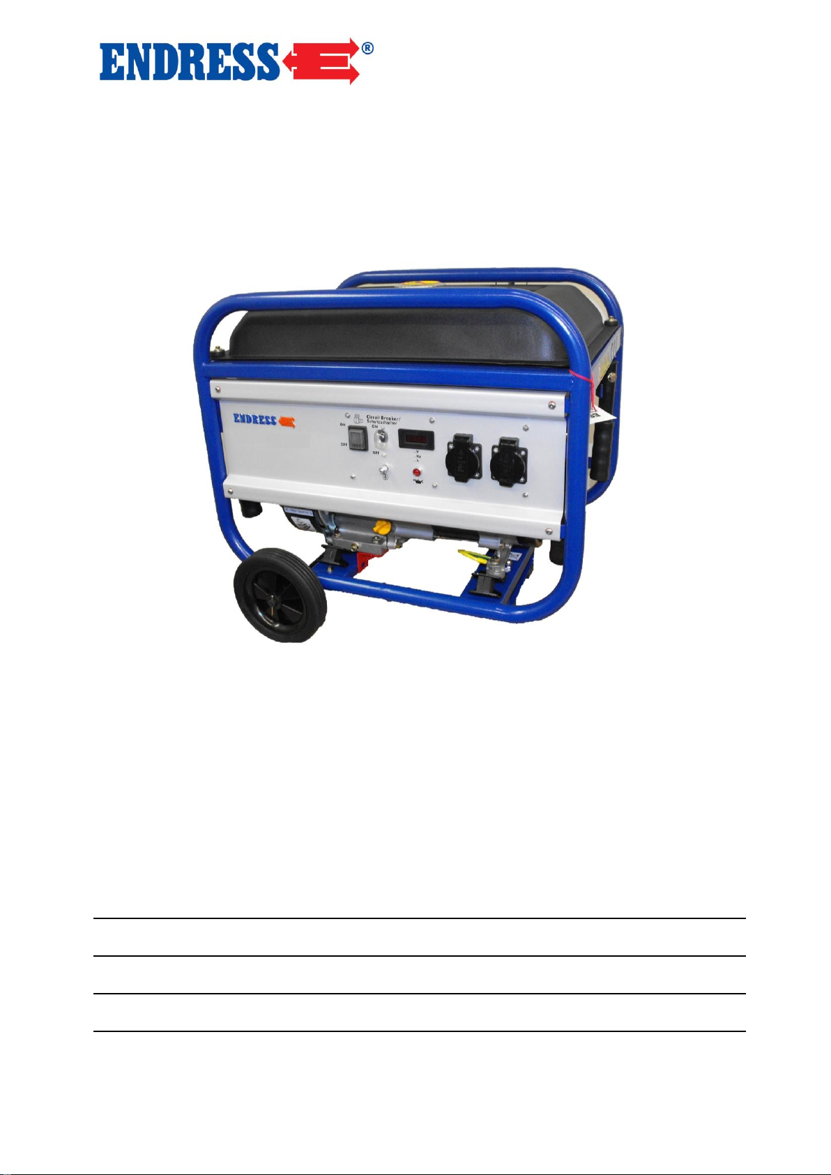
Endress ESE 606 HS-GT ES, ESE 606 DHS-GT, ESE 306 HS-GT, ESE 606 DHS-GT ES, ESE 606 HS-GT User guide
...Page 1
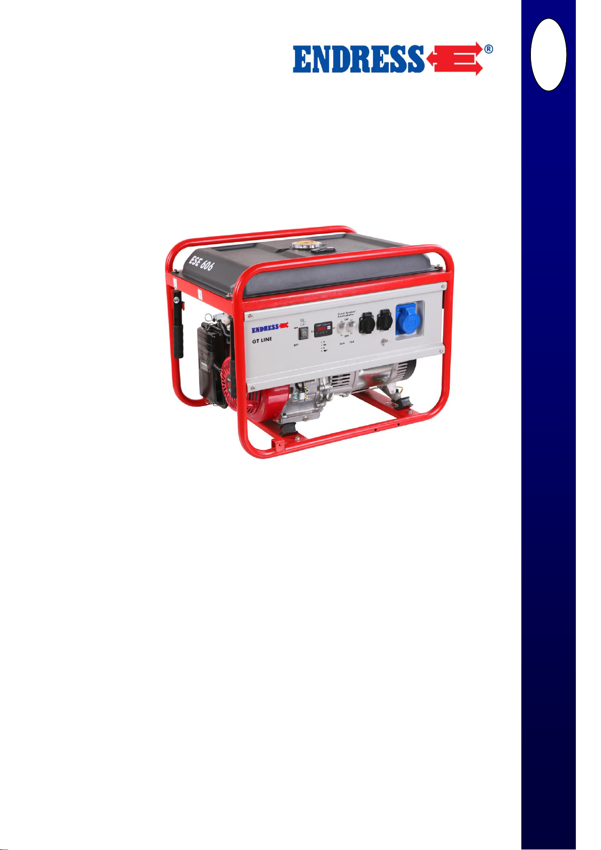
OPERATING
INSTRUCTIONS
Hond
a
GT
-L
INE
Power Generators
GB
www.endress
-gener
ators.de
ESE 306 HS-GT
Article-No. 112 210
ESE 606 HS-GT
Article-No. 112 211
ESE 606 HS-GT ES
Article-No. 112 212
ESE 606 DHS-GT
Article-No. 112 213
ESE 606 DHS-GT ES
Article-No. 112 214
Page 2

Operating Instructions
2
ENDRESS Elektrogerätebau GmbH
Neckartenzlinger Straße 39
D-72658 Bempflingen
Email: [email protected]
WWW: http://www.endress-generators.de
E135693
August 2016
© 2016, ENDRESS Elektrogerätebau GmbH
This documentation, including all parts thereof, is protected
by copyright. Every use and adaptation outside of what is
strictly authorised under the copyright law is, without the
permission of the ENDRESS Elektrogerätebau GmbH Company, illegal and punishable by law.
This applies in particular to reproductions, translations, copying by microfilming and storage and processing in electronic
systems.
Published by
Document number
Date of issue
Copyright
Page 3

About these instructions
Signs and Symbols used
3
List of Contents
1 About these instructions .................................................................................. 5
1.1 Signs and Symbols used .................................................................................... 6
1.1.1 General Signs / Symbols ......................................................................................... 6
1.1.2 Safety symbols………. ............................................................................................ 7
2 General Safety Guidelines ................................................................................ 8
2.1 Intended Use ..................................................................................................... 8
2.1.1 Intended use…………. ............................................................................................ 8
2.1.2 Foreseeable misuse and incorrect operation .......................................................... 9
2.1.3 Residual Risks……….. ..........................................................................................10
2.2 Qualifications and Duties ................................................................................. 12
2.3 Personal Safety Equipment .............................................................................. 12
2.4 Hazard Areas and Work Places ....................................................................... 12
2.5 Labelling on the Power Generator .................................................................... 13
2.6 General Safety Instructions .............................................................................. 15
3 Description ...................................................................................................... 19
3.1 Function and Mode of Operation ................................................................ ...... 20
4 Putting the Power Generator into Operation ................................................ 21
4.1 Dismantle the transport safety device .............................................................. 21
4.1 Transporting the Power Generator ................................................................... 22
4.2 Setting-up the Power Generator ....................................................................... 23
4.3 Fuelling the Power Generator .......................................................................... 24
4.4 Filling the Power Generator with Motor Oil ....................................................... 25
4.5 Starting the Power Generator........................................................................... 27
Page 4

About these instructions
Signs and Symbols used
4
4.6 Switching off the Power Generator ................................................................... 33
4.7 Shutting down Power Generator (longer term shut down) ................................ 34
5 Servicing the Power Generator ...................................................................... 38
5.1 Service Plan ..................................................................................................... 38
5.2 Servicing work ................................................................................................. 39
5.3 Checking Electrical Safety ............................................................................... 39
6 Trouble Shooting ............................................................................................ 40
7 Technical Data ................................................................................................. 42
8 Terms of Warranty .......................................................................................... 45
Page 5

About these instructions
Signs and Symbols used
5
1 About these instructions
Before you use this power generator, carefully read and
make sure you understand these instructions.
These instructions are intended to enable you to understand
the basic operating principles of the power generator.
These instructions contain important information on how to
use this power generator in a correct and safe manner.
Following the instructions will help:
to avoid dangers
to minimise costs of repair and down-time
to increase the dependability and operational life of the
power generator.
Irrespective of these instructions, the laws, regulations and
guidelines of the country and location where the generator is
operated must be observed.
Irrespective of these instructions, the locally applicable laws
for health and safety and the regulations for the protection of
the environment pertaining to the country and location where
the generator is operated must be observed.
These instructions only provide information regarding the
use of the power generator.
A copy of these instructions must be made available at all
times to the operating personnel.
Page 6
About these instructions
Signs and Symbols used
6
1.1 Signs and Symbols used
The signs and symbols in these instructions are designed to
assist in the understanding of the instructions and to enable
the operator to commence use of the generator quickly and
safely.
1.1.1 General Signs / Symbols
Advanced Organizer
The Advanced Organizer provides brief information on the
content of the following section.
Notes provide hints and information to assist you to make
the most effective and practical use of the generator and
these instructions.
The prescribed order of the work steps will make it easier for
you to operate the generator correctly and safely.
Result
Here you will find the description of the result achieved by
the completion of the work steps.
NOTE
1. Work steps
2. ….
3. ….
Page 7
About these instructions
Signs and Symbols used
7
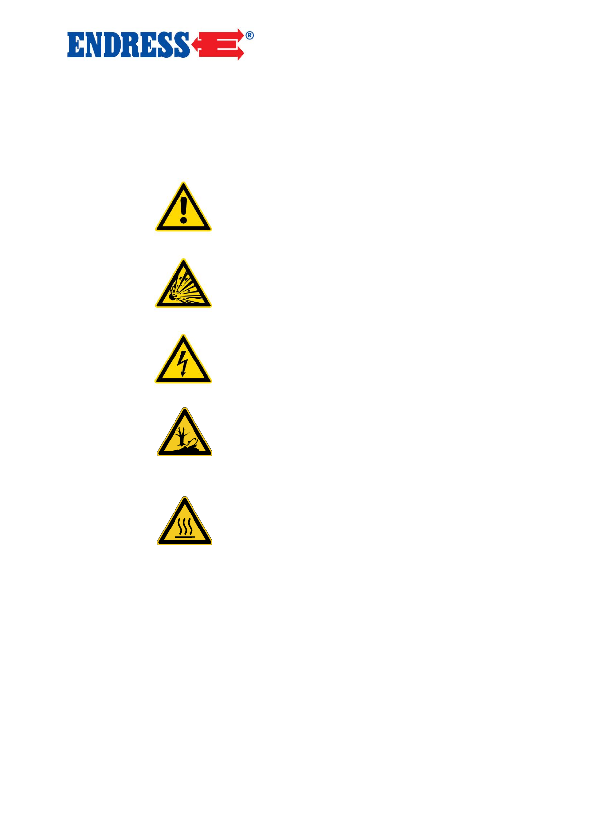
1.1.2 Safety symbols
Safety symbols highlight a source of danger.
Warning about a general danger
These warning symbols indicate activities that could lead to
several sources of danger.
Warning about explosive materials
These warnings symbols indicate activities that could lead to
the risk of explosion with possibly fatal consequences.
Warning about danger from electrical voltage
These warning symbols indicate activities that could lead to
the risk of an electric shock with possibly fatal consequences.
Warning on environmentally damaging substances
This warning sign indicates activities, during which the environment could be endangered, possibly with catastrophic
consequences.
Warning on hot surfaces
This warning sign indicates activities, during which there is
the danger of burns, possibly with lasting consequences.
Page 8

General Safety Guidelines
Intended Use
8
2 General Safety Guidelines
In this section you will find the basic safety guidelines for
operation of the power generator.
Every person who operates the power generator, or works
with someone who operates the power generator is obliged
to read this chapter and observe the guidelines when operating the power generator.
2.1 Intended Use
The power generator conforms to the most up-to-date standards of science and technology, as well as to the safety
regulations currently applicable at the time the product is put
into circulation.
Incorrect use and residual risks cannot be constructively
prevented without reducing the function of the intended use.
Information about risks of danger is conveyed either directly
by the generator itself and/or by the technical documentation.
2.1.1 Intended use
The power generator is a mains replacement that generates
electrical power for supply to a mobile distribution system.
The power generator must be operated outdoors within the
prescribed voltage, output and rated speed limits (see type
plate).
The power generator must not be connected to other electri-
cal supply systems (e.g. public electrical supply) or electric
generation systems (e.g. other power generators).
The power generator may not be used in environments
where there is a risk of explosion.
The power generator may not be used in environments
where there is a risk of fire.
The power generator must be operated in accordance with
the conditions set out in the technical documentation.
Page 9

General Safety Guidelines
Intended Use
9
All improper use of the power generator including all uses
not described in these instructions will constitute unauthorised incorrect usage for which the manufacturer is not legally
liable.
2.1.2 Foreseeable misuse and incorrect operation
Instances of foreseeable misuse and/or incorrect operation
of the power generator invalidate the manufacturer’s EU declaration of conformity, together with the operating license.
Foreseeable misuse and/or incorrect operation includes:
Operation in environments where there is a risk of explo-
sion
Operation in environments where there is a risk of fire
Operation in enclosed areas
Operation under direct exposure to rain or snowfall
Operation without the requisite safety precautions
Operation connected to existing supply network systems
Refuelling when hot
Refuelling when in operation
Spraying with high-pressure cleaners or fire extinguishing
equipment
Operation when safety devices are removed
Non-compliance with regular servicing requirements
Failure to carry out measurements and checks for early
detection of defects.
Failure to replace wear and tear parts
Improper servicing and repairs
Inadequate servicing and repairs
Incorrect operation
Page 10

General Safety Guidelines
Intended Use
10
2.1.3 Residual Risks
Analysed and evaluated by means of a risk assessment undertaken prior to the planning and construction of the power
generator.
Residual risks that are constructively unavoidable and which
may arise during the operating life of the power generator
are:
Danger to life
Risk of injury
Environmental hazards
Material damage to the power generator
Material damage to other material property
Reduction in performance and functionality
You can avoid existing residual risks by implementing and
observing the following guidelines:
the special warning notices on the power generator
the general safety notices in these instructions
the special warning notices in these instructions
Danger to the life of persons from the power generator can
arise through:
Misuse
Incorrect operation
Improper safety equipment
Defective or damaged electrical components
Touching with wet hands
Fuel vapours
Engine exhaust fumes
Risk of injury to persons from the power generator can arise
through:
Incorrect operation
Transportation
Hot parts
Recoil of the Engine starter cable
Danger to Life
Risk of Injury
Page 11

General Safety Guidelines
Intended Use
11
Environmental hazards from the generator can arise from:
Incorrect operation
Operating materials (fuel, lubricants, Engine oils etc.)
Exhaust emissions
Sound emissions
Risk of fire
Material damage to the electrical generator can arise from:
Incorrect operation
Overloading
Over heating
Too low / too levels of high Engine oil
Failure to observe operating and servicing guidelines
Use of improper operating materials
Material damage to other property in the vicinity of the power
generator can arise from:
Incorrect operation
Excess or undervoltage
Reduction in the performance or function of the power generator can arise from:
Incorrect operation
Incorrect servicing or repair
Unsuitable operating materials
An operational location more than 100 meters above sea
level
An ambient temperature above 25°C
Excessive size of the distribution network
Environmental Hazards
Material damage to the
Electrical Generator
Material Damage to
other Property
Reduction in the
Performance and
Functionality
Page 12
General Safety Guidelines
Qualifications and Duties
12
2.2 Qualifications and Duties
All activities in relation to the electrical generator may only
be carried out by personnel qualified for this purpose.
They must
know and apply the Prevention of Injury regulations and
the safety instructions for the power generator.
have read the "General Safety Guidelines" section.
have understood the contents of the "General Safety
Guidelines" section.
be able to practically implement the contents of the
"General Safety Guidelines" section.
understand and be able to practically implement the
technical documentation.
2.3 Personal Safety Equipment
You must wear the following personal safety equipment during all activity with the power generator as described in these
instructions:
Hearing protection
Protective gloves
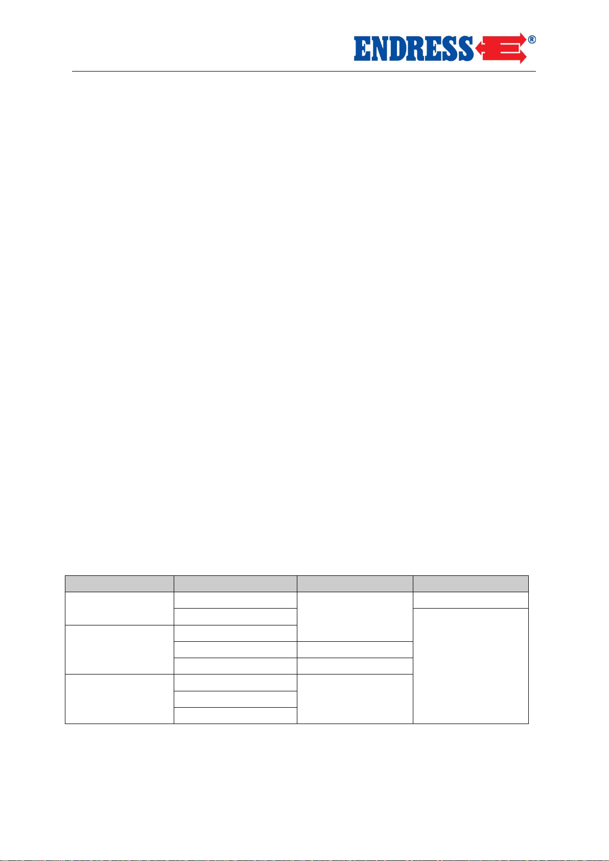
2.4 Hazard Areas and Work Places
The hazard areas and work places (work areas) for the power generator are defined for the activity undertaken within the
individual work phase:
Work Phase
Activity
Hazard Area
Work Area
Transportation
In vehicle
Radius of 1.0 m
none
By operating personnel
Radius of 1.0 m
Operation
Set up
Operating
Radius of 5.0 m
Re-fuelling
Radius of 2.0 m
Maintenance and
Servicing
Cleaning
Radius of 1.0 m
Shut down
Servicing
Tab. 2.1: Hazard Areas and Work Places of the Power Generator
Page 13
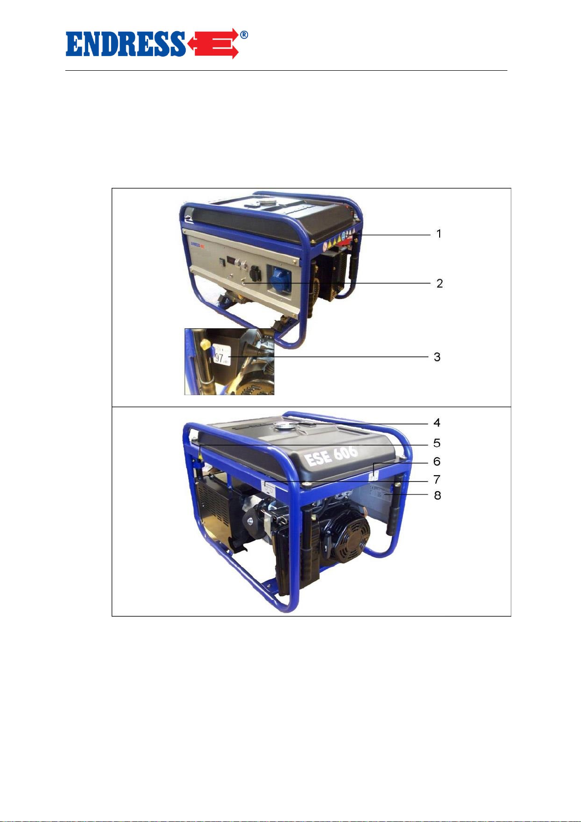
2.5 Labelling on the Electrical Generator
1
General warnings
5
Hot surface warning
2
Earth
6
Fuel cock warning
3
Sound power level warning
7
Choke (cold start) warning
4
Fire hazard warning
8
Model plate
These labels must be attached to the electrical generator
and be easy to read:
These
General Safety Guidelines
Labelling on the Electrical Generator
Fig. 2.1: Labels on the generator
13
Page 14
General Safety Guidelines
Labelling on the Electrical Generator
14
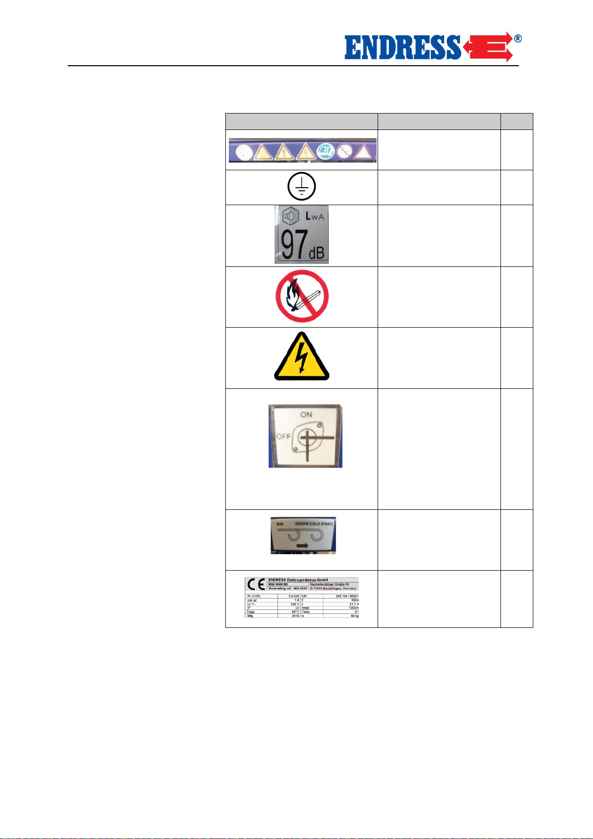
Label
Designation
No.
General warnings
1
Earth
2
Sound power level
warning
3
Fire hazard warning
4
Hot surface warning
5
Fuel tap warning
6
Choke
7
Model plate
See page 40 for explanation
8
Tab. 2.2: Labels on the generator
Page 15

General Safety Guidelines
General Safety Instructions
15
2.6 General Safety Instructions
The operator must know the functions of, and be able to use,
the components of the power generator.
The operator is responsible for the safe operation of the
power generator.
The operator is responsible for preventing unauthorized use
of the power generator.
The operator must wear the appropriate personal safety
equipment.
The labelling on the electrical generator must be complete
and maintained in a readable condition.
Constructive changes may not be carried out on the electrical generator.
The rated speed of the motor has been set during manufacture and may not be changed.
The operating safety and correct functioning must be
checked before and after each use.
The power generator may only be used outside.
No naked flames, lights or spark-emitting appliances may be
used within the hazard area of the power generator.
Smoking within the hazard area of the power generator is
strictly forbidden.
During operation, the power generator must be protected
against dampness and precipitation (rain, snow).
During operation, the power generator must be protected
from dirt and foreign matter.
Page 16

General Safety Guidelines
General Safety Instructions
16
The power generator may only be transported when cold.
The power generator may only be transported by vehicle
where there is adequate protection against tipping.
The power generator may only be lifted using the carry han-
dles intended for this purpose.
The power generator may only be set up on adequately stable surfaces.
The power generator may only be set up on even surfaces.
The power generator may not be set up on wet surfaces.
The electrical safety must be checked before each operational use.
The appliance may not be covered.
The air intake may not be blocked or obstructed.
Starting aids may not be used.
When starting, the load may not be connected.
Only certified and approved cables may be used for the
wired network.
The power output may not exceed the maximum rated
power.
The power generator may not be operated without the
sound absorber.
The power generator may not be operated without the air
filter or with the air filter cover open.
Transporting
Set up
Power generation
Page 17

General Safety Guidelines
General Safety Instructions
17
The generator’s tank may not be refilled during operating.
The tank may not be refilled when the power generator is hot.
Use a filling device (funnel) when re-filling.
The power generator may not be cleaned when in operation.
The power generator may not be cleaned when hot.
The power generator may not be serviced when in operation.
The power generator may not be serviced when hot.
The operator may only carry out servicing and repair work
that conforms to these instructions.
All other servicing and repair work may only be carried out
by personnel who are qualified and licensed for this purpose.
Always remove spark plug connector prior to commencing
servicing and repair work.
The service intervals set out in these instructions must be
observed.
The power generator must be shut down when not required
for periods longer than 30 days.
The power generator must be stored in a dry enclosed room.
A fuel additive should be used to prevent resinous residues.
Fuelling
Cleaning
Maintenance and
Servicing
Shut down
Page 18

General Safety Guidelines
General Safety Instructions
18
The packaging material should be recycled in accordance
with the locally applicable regulations for the protection of the
environment.
To prevent contamination the operational location must be
protected against the leakage of operating materials.
Used or residual operating materials should be recycled in
accordance with the locally applicable regulations for the
protection of the environment.
Electrical and electronic devices, batteries and rechargeable
batteries may not be disposed of in domestic waste.
The user is legally obliged to return electrical and electronic
devices, batteries and rechargeable batteries, at the end of
their useful life, to the designated public collection facilities or
to the point of sale. This is indicated either by the symbol on
the product, the instructions for use or the packaging.
Batteries and rechargeable batteries must be removed from
devices and disposed of separately.
You are making an important contribution to the protection of
our environment by carrying out recycling, material recycling
or other forms of recycling of used appliances and devices.
Notice on Protection
of the Environment
Page 19
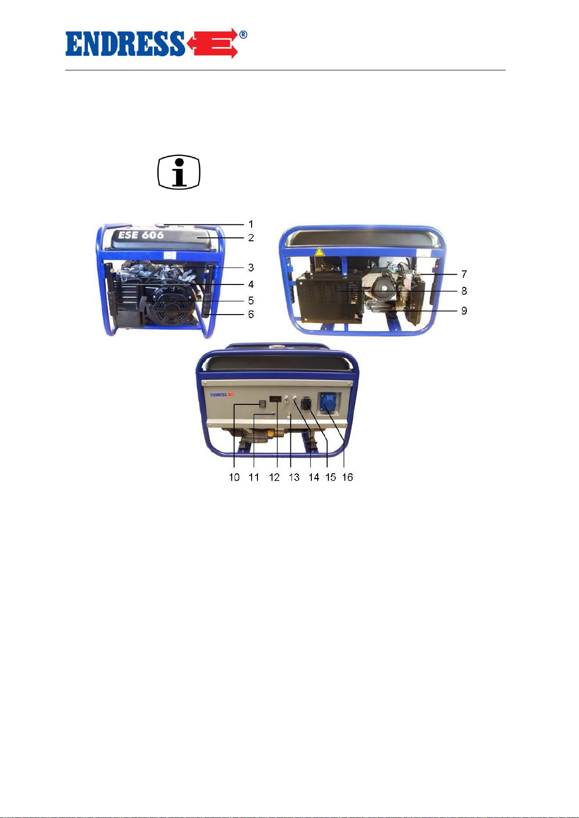
3 Description
1
Fuel cap
9
Oil drain plug
2
Fuel tank
10
Rocker switch for Engine (On/Off)
3
Fuel valve
11
Low oil light
4
Air filter
12
Volt./Freq./Hrs meters
5
Rope starter for motor
13
Ground connection screw
6
Carrying handle
14
Circuit breaker
7
Choke
15
Electric safety socket
8
Muffler
16
CEE socket
Description
This section describes the power generator’s components
and functions.
=
Fig. 3.1: Components of the generator
19
Page 20

Description
Function and Mode of Operation
20
3.1 Function and Mode of Operation
The synchronous generator is rigidly coupled to the drive
Engine. The aggregate is mounted on a stable base plate
and is housed elastically in a low vibration state.
Power consumption is via a splash-proof shock-proof 230 V /
50 Hz socket.
The generator’s voltage regulation is provided within rated
speed limits by an automatic voltage regulator (AVR)
AVR = Automatic Voltage Regulator
The AVR evens out voltage peaks making it especially suitable for electronic loads, e.g. electronically regulated power
tools such as drills as well as domestic appliances such as
cookers, heaters, television etc.
The power generator is designed for mobile operation with
one or several loads. Stationary operation required.
The power generator’s potential equalization (protective
separation) is implemented by means of a separate cable
that must be connected to a device that is suitable for earthing. (not supplied)
Page 21
Putting the Power Generator into Operation
Transporting the Power Generator
21
4 Putting the Power Generator into Operation
This section describes the operation of the power generator.
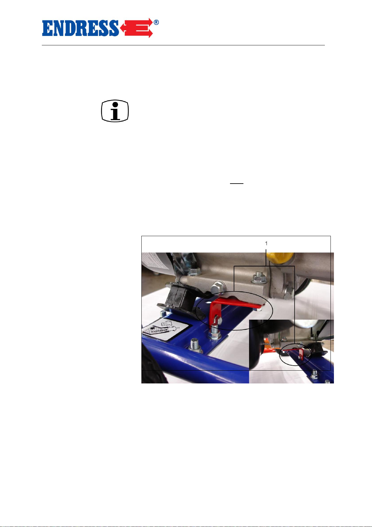
4.1 Dismantling the transport safety device
1. Undo securing screws at both ends of the red transport
safety devices (see Fig. -2- (1)).
2. Now remove the safety devices.
Dismantling the safety devices has now been completed.
Figure 2: Transport safety device
Keep the two transport safety devices and the screws safely
in case they will be needed again.
Note
Page 22
Description
Function and Mode of Operation
22
4.2 Transporting the Power Generator
Proceed as follows when transporting the power generator.
These requirements must be fulfilled:
Power generator is turned off
Power generator has cooled down
Air vent is in the OFF position
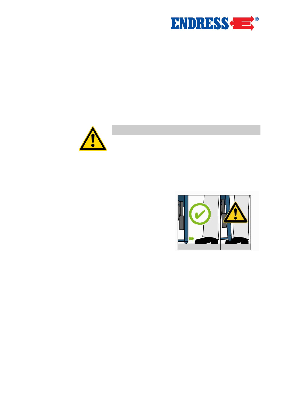
CAUTION!
A slipping or falling generator can crush hands or feet.
Beware of weight — 30 to 92 kg (depending on model).
The device must be carried by 2 people (ESE 1100 BS /
ESE 2000 BS) or 4 people (ESE 4000 BS / ESE 6000
BS).
Walk slowly.
Keep feet out from under the device.
3. Take firm hold of carry grips.
4. Lift appliance.
5. Carry appliance to operating point.
6. Lower appliance.
7. Release carry grip.
The appliance has been carried to the operating point.
Requirements
Carrying the appliance
Page 23
Putting the Power Generator into Operation
Transporting the Power Generator
23
4.3 Setting-up the Power Generator
Proceed as follows in order to set-up the power generator.
These requirements must be fulfilled:
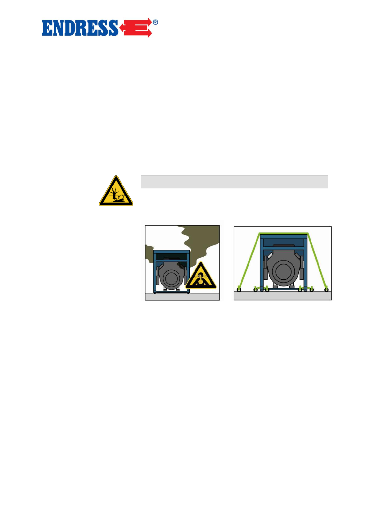
level and stable surface outdoors
operating area is free of flammable materials
operating area is free of explosive materials
The device must be set up in the open (it must not be
covered).
CAUTION!
Leaking engine oil and petrol can contaminate soil and
groundwater.
Prevent engine oil and petrol leaks.
The generator is set up as follows:
1. Prepare the work area.
2. Transport the generator to the work area.
3. If necessary, secure the device against tilting or slipping.
The device has now been set up.
Requirements
Setting up the generator
Page 24
Putting the Power Generator into Operation
Setting-up the Power Generator
24
4.4 Fuelling the Power Generator
Proceeds as follows to fuel the power generator.
These requirements must be fulfilled:
appliance is switched off
appliance is cool
adequate air supply and ventilation
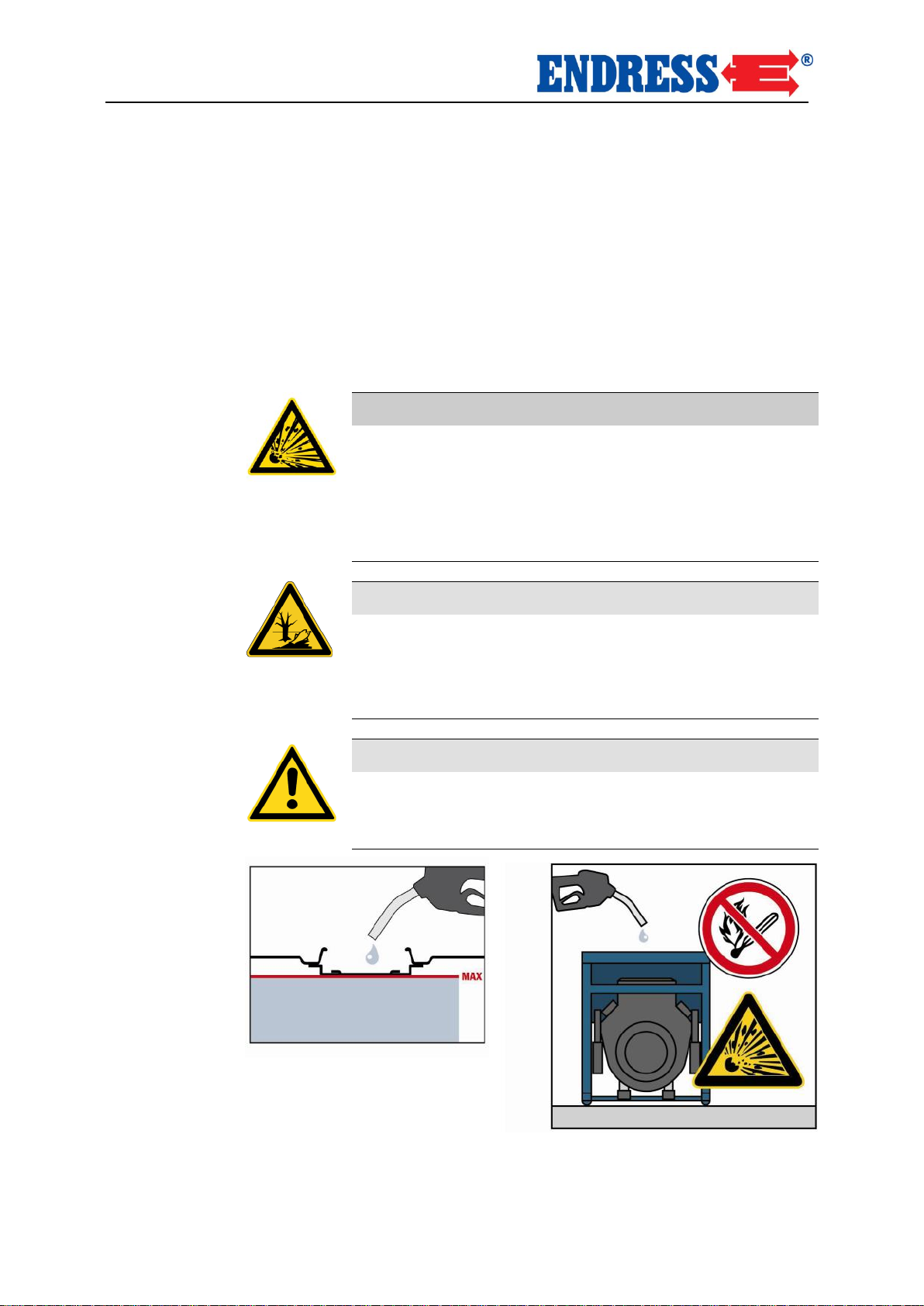
WARNING!
Leaking fuel can combust or explode.
Avoid fuel leakages.
Appliance is switched off.
Appliance is cooled.
Avoid naked flames and sparks.
CAUTION!
Leaking engine oil can contaminate soil and groundwater.
Do not fill the tank completely.
Use pour spout.
CAUTION!
Incorrect fuel destroys the engine.
Only refuel with lead-free regular grade petrol ROZ 91.
Requirements
Page 25
Putting the Power Generator into Operation
Fuelling the Power Generator
25
The power generator is fuelled as follows:
1. Push the fuel valve to the OFF position
2. Unscrew the tank cap.
3. Insert filling device (funnel) into the tank.
4. Fill with fuel.
5. Remove the filling device.
6. Replace the tank cap
The appliance is fuelled.
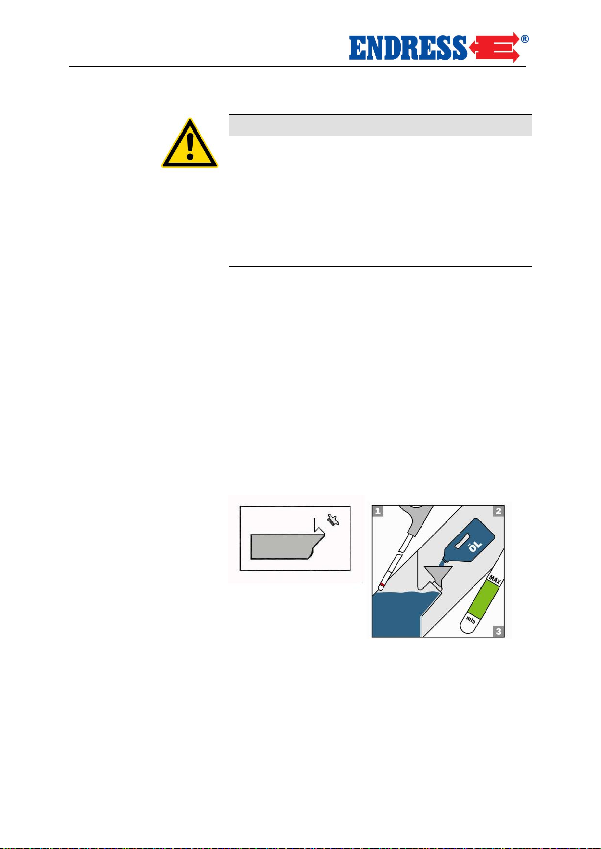
4.5 Filling the Power Generator with Motor Oil
WARNING!
The power generator is, as a rule, delivered without oil.
it is not possible to start the appliance if the oil level is
too low, because the motor is fitted with an oil monitor.
Proceed as follows to fill the appliance with motor oil.
These requirements must be fulfilled:
appliance is switched off
appliance is cool
WARNING!
Leaking motor oil contaminates the soil and ground
water.
Do not fill crankcase to maximum (check the volume
with oil dipstick).
Use filling device (funnel).
Fuelling the appliance
Requirements
Page 26
Putting the Power Generator into Operation
Filling the Power Generator with Motor Oil
26
WARNING!
Incorrect motor oil will damage motor irreparably.
Please check the ambient temperature and fill with the
following listed oil type:
…. < 0° => SAE 10 or 10W30; 10W40
0°-25° => SAE 20 or 10W30; 10W40
25°-35° => SAE 30 or 10W30; 10W40
35° > … =>SAE 40 or 10W30; 10W40
Do not add any standard additives to the oil.
Proceed as follows to fill the power generator with motor
oil:
1. Unscrew oil dipstick.
2. Insert filling device (funnel) into the opening.(not supplied)
3. Fill motor oil up to the edge of the oil-filler neck.
(Oil quantity, see page 40 "Technical data").
4. Remove filling device.
5. Replace oil dipstick.
6. If oil level is too low, repeat filling procedure.
7. Tighten oil dipstick
The appliance is filled with motor oil.
Filling the appliance
with motor oil
Page 27
Putting the Power Generator into Operation
Filling the Power Generator with Motor Oil
27
4.6 Starting the Power Generator
Proceed as follows in order to start the power generator.
These requirements must be fulfilled:
electrical safety is checked
fuel tank is filled
adequate oil level
adequate air supply and ventilation
load is switched off or disconnected
WARNING!
Operating materials can combust or explode.
Avoid leakage of motor oil and fuel.
Do not use ignition aids.
Avoid naked flames and sparks.
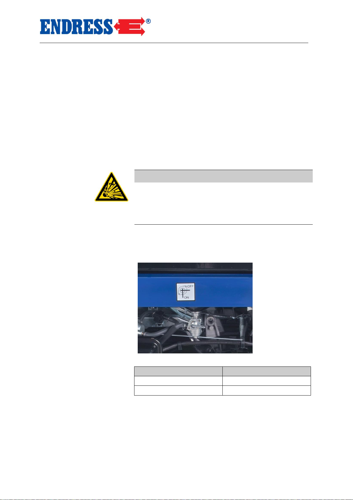
Engine fuel supply is by means of the power generator’s own
fuel tank.
Fig. 4.1: Open/close fuel valve
Switch position
Function
OFF
Closed
ON
Open
Tab. 4.1: Air vent switch position.
You turn on the engine fuel supply as follows:
1. Air vent switch to position ON.
The engine fuel supply is turned on.
Requirements
Turn on engine fuel supply
Page 28
Putting the Power Generator into Operation
Starting the Power Generator
28
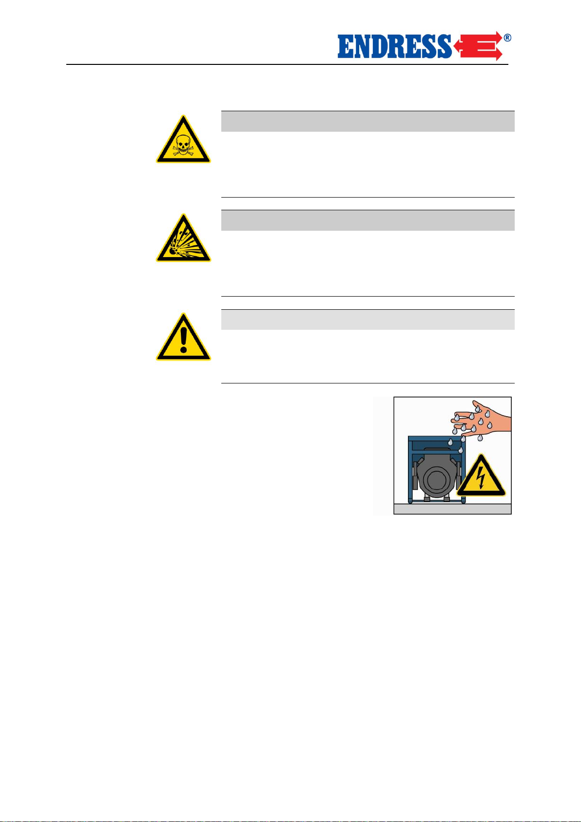
WARNING!
Exhaust fumes affect the respiratory system with potentially fatal consequences.
Ensure there is adequate ventilation.
Only use appliance outdoors.
WARNING!
Hot components can ignite flammable and explosive
materials.
Avoid flammable materials at operating area.
Avoid explosive materials at operating area.
WARNING!
Heat or wetness damages the appliance irreparably.
Avoid overheating (adequate ventilation).
Avoid wetness.
Page 29
Putting the Power Generator into Operation
Starting the Power Generator
29
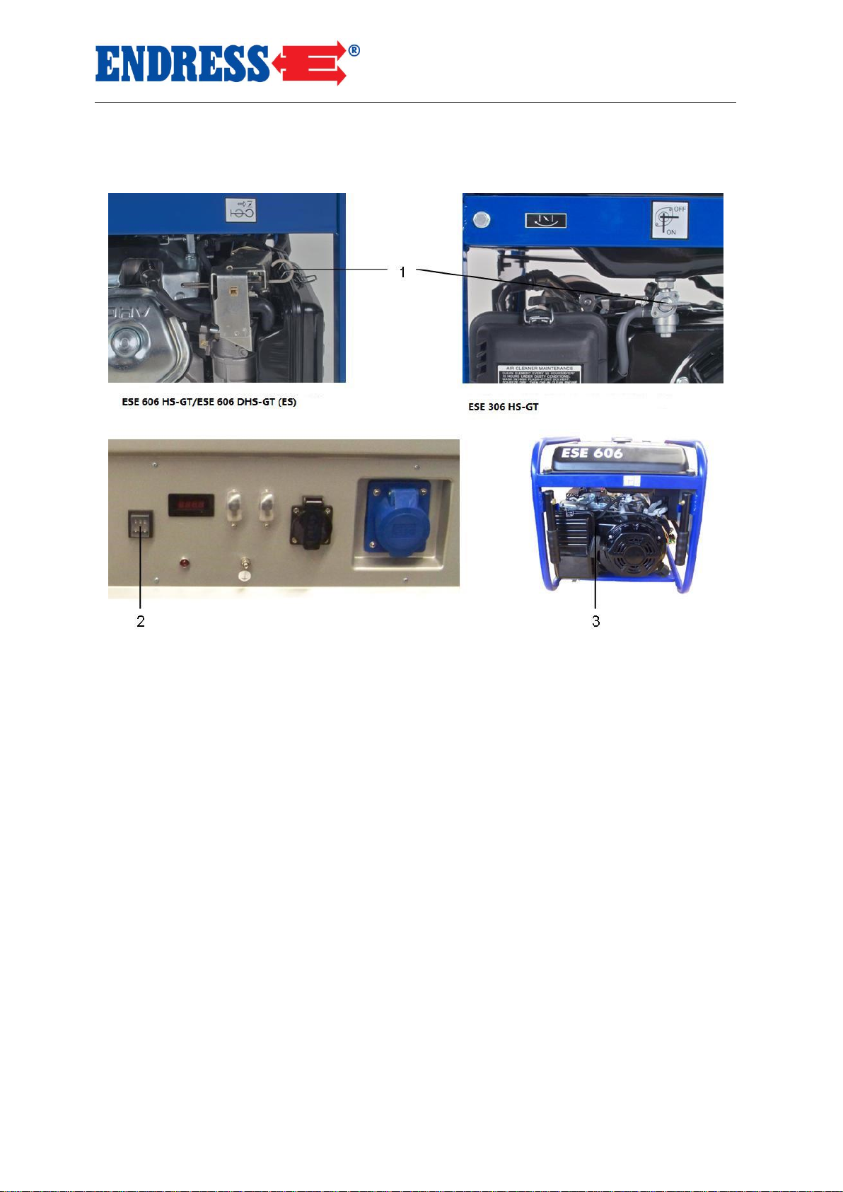
You start the motor as follows:
Fig. 4.2: Starting the engine
1
Choke (cold start)
2 Rocker switch for motor (Position - ON)
3
Rope starter for motor
1. Push choke lever to START position “see air filter label”
(for cold engine only).
2. Push Rocker switch of motor to ON position.
3. Pull cable grip slowly out to point of action, then pull with
a swift but fluid movement.
The motor begins to start.
In order to ease the pulling action, brace yourself with one
hand on the appliance grip,
4. Push the choke level to the RUN position.
The motor is started.
Starting the motor
Page 30

Putting the Power Generator into Operation
Starting the Power Generator
30
1. Move choke into the start position “see air filter label”
(only if motor is cold).
2. Turn the key-switch to the right and hold it in the START
position until the motor starts and then release it.
The motor starts up.
4. Move the choke into the start position.
The motor has started.
Activate the starter briefly (max. 5 – 10 sec). Never start the
motor or leave it to run with a battery clamped on it.
The electrical consumer can be connected up or switched in
after a warming-up phase of approx. one minute has been
completed.
ELECTROSTART
NOTE
NOTE
Page 31
Putting the Power Generator into Operation
Starting the Power Generator
31
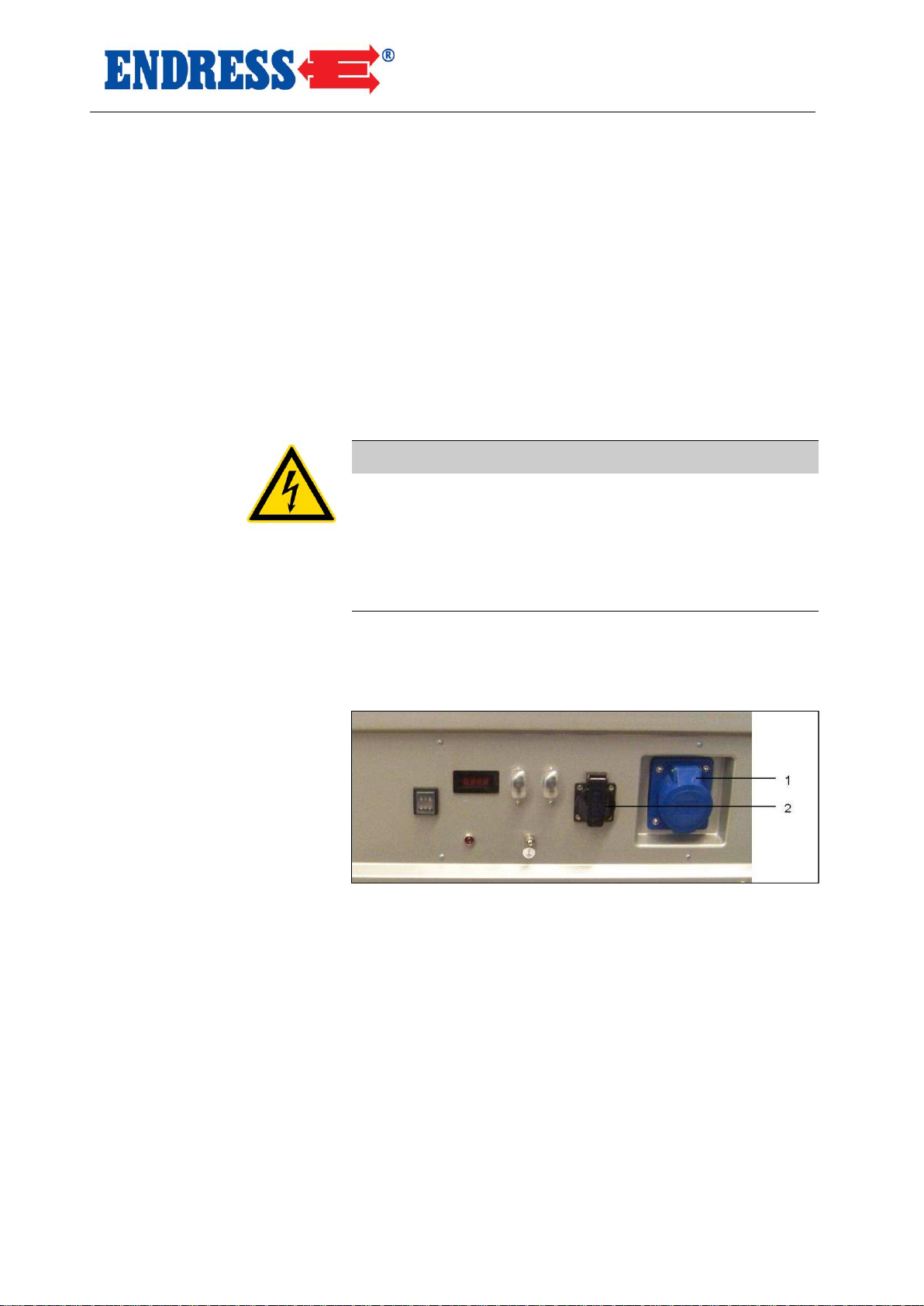
Proceed as follows to connect the load to the power generator.
The following requirements must be fulfilled:
the power generator is started
warm up period is complete
load is turned off
WARNING!
Electric shocks cause injuries with potentially fatal
consequences.
The power generator must not be connected to other
electric supply systems (e.g. public supply systems) or
electrical generation systems (e.g. other power generators).
You can use a safety plug (230V AC) or (400V 3-phase AC
for ESE 6000 DBS (ES) only) to interconnect the consumers.
Fig. 4.3: Connecting consumers
1 CEE socket 2 Electric safety socket 230 V 1~
Requirements
Connecting load
Connecting load
Page 32

Putting the Power Generator into Operation
Starting the Power Generator
32
Proceed as follows to connect a load to the shockproof
socket:
1. Lift cover.
2. Insert shock-proof plug.
The load is connected to the power generator.
You switch on the load as follows:
1. Switch on load.
The load is switched on.
You switch off the load as follows:
1. Switch off load.
The load is switched off.
You disconnect the load from the power generator as
follows:
1. Remove plug.
The load is disconnected from the power generator.
Connecting load
Switch on load
Switch off load
Disconnect load
Page 33
Putting the Power Generator into Operation
Switching off the Power Generator
33
4.7 Switching off the Power Generator
Proceed as follows to switch off the power generator.
WARNING!
Hot components can ignite flammable and explosive
materials.
Avoid flammable materials at the operating area.
Avoid explosive materials at the operating area.
Allow appliance to cool.
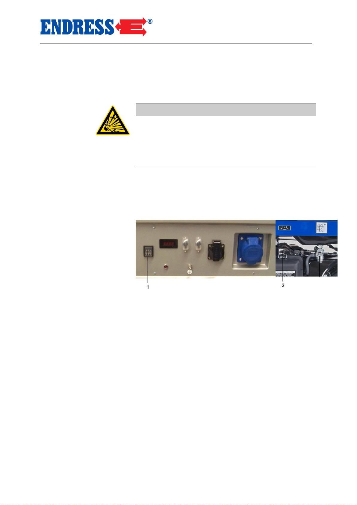
You switch off the appliance as follows:
1. Switch off or disconnect load.
2. Allow motor to continue running for approx. a further two
minutes.
Fig. 4.4: Turn off the motor
1
Rocker switch for motor (Position - ON)
2 Choke (cold start)
3. Push the Rocker switch of motor to the OFF position.
The motor is off.
4. Push fuel valve switch to the OFF position.
5. Allow appliance to cool.
The appliance is switched off.
Page 34
Putting the Power Generator into Operation
Shutting down Power Generator (longer term shut down)
34
4.8 Shutting down Power Generator (longer term shut down)
Starting problems may be experienced if the electrical generator is only used infrequently.
To avoid these problems the generator should be run for
approx. 30 minutes per week.
If you do not require the power generator for a longer period
of time, shut the generator down and put it into storage.
Proceed as follows to shut down the generator.
These requirements must be fulfilled:
load is switched off or disconnected
appliance is switched off
appliance is still a little warm
WARNING!
Leaking motor oil and fuel contaminates the soil and
ground water.
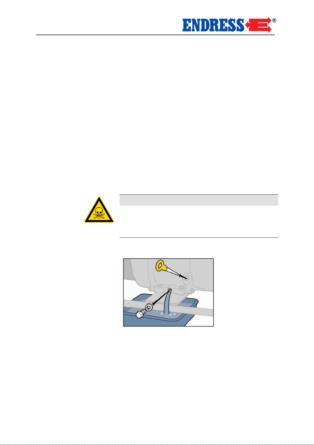
Drain the motor oil from generator as follows:
Fig. 4. 5: Remove the oil drain plu
1. Hold catchment tank under the oil drain screw
Infrequent use
Storage
Requirements
Draining motor oil
Page 35
Putting the Power Generator into Operation
Shutting down Power Generator (longer term shut down)
35
The catchment tank capacity varies depending on the model
(0.5 or 1.5 litre). Precise details can be found on page 40 in
the “motor oil fill” table.
2. Use wrench to loosen and remove oil drain screw
3. Drain engine oil
Used or residual operating materials should be disposed of
according to the locally applicable recycling regulations for
the protection of the environment.
4. Replace oil drain screw and tighten with wrench
The motor oil is drained.
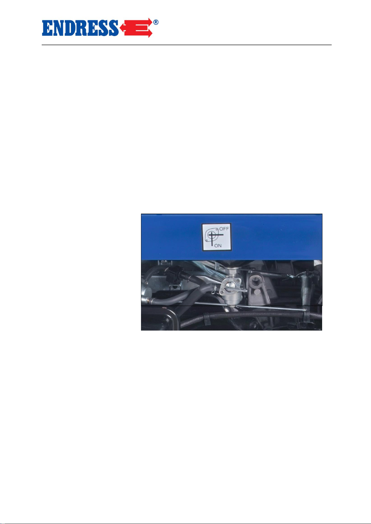
Proceed as follows to empty generator’s fuel tank:
Fig. 4.6: Shut the fuel valve
1. Place the catchment tank beside the generator.
The catchment tank capacity varies depending on the model.
Precise details can be found on page 40 in the “Tank con-
tents” table.
Push fuel valve switch to the OFF position
2. Carefully disconnect fuel pipe from carburettor and allow
to drain into catchment tank.
3. Push fuel valve switch to the ON position
Fuel is drained.
Used or residual operating materials should be disposed of
according to the locally applicable recycling regulations for
the protection of the environment
Note
Protection of the
environment
Drain fuel tank
NOTE
Protection of the
environment
Page 36
Putting the Power Generator into Operation
Shutting down Power Generator (longer term shut down)
36
Push fuel valve switch to the OFF position
4. Carefully reconnect the fuel pipe to the carburettor
Fuel is drained.
You conserve the engine compartment as follows:
These requirements must be fulfilled:
appliance is turned off
no more fuel in the tank
Fuel valve in OFF position
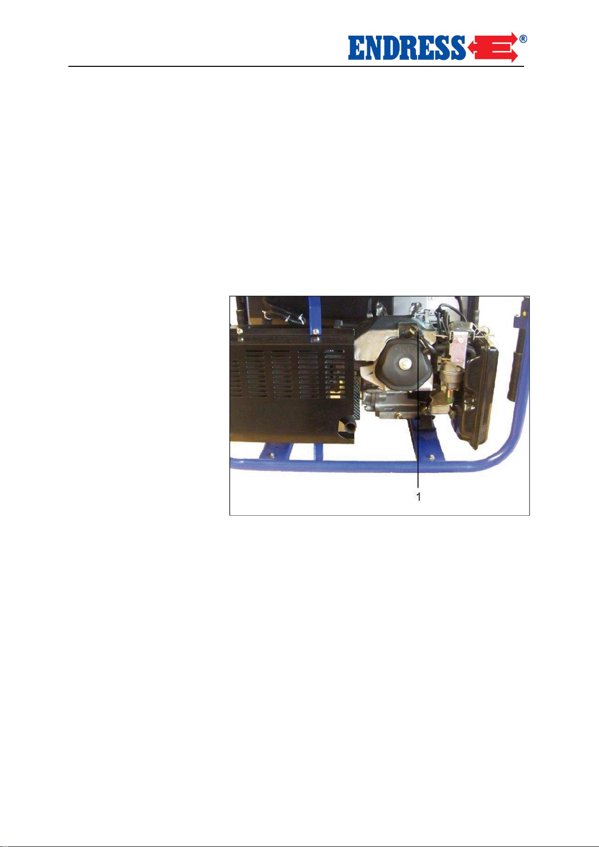
Fig. 4.7: Pull off the spark plug connector
1. Remove spark-plug connector
2. Remove spark-plug with a spark-plug wrench.
3. Apply approx. 1 ml oil to the spark-plug aperture.
4. Screw spark-plug back in and tighten.
5. Pull the starter cable several times slowly so that the oil
is distributed around the engine compartment.
6. Re-insert the spark-plug connector
The engine compartment is conserved.
Conservation of engine
compartment
Requirements
Page 37
Putting the Power Generator into Operation
Shutting down Power Generator (longer term shut down)
37
The air filter of the generator is cleaned as follows:
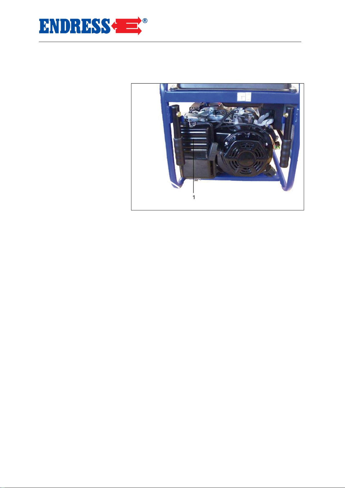
Fig. 4.8: Remove the air filter
1. Remove air filter cover from air filter housing
2. Clean the air filter insert in a suitable container in warm
water with dish detergent or with nonflammable cleaning
solvent.
3. Pour some motor oil onto the filter and press out excess
oil.
4. Replace air filter
5. Replace air filter cover onto air filter housing
Air filter is cleaned and mounted.
Used or residual operating materials should be disposed of
according to the locally applicable recycling regulations for
the protection of the environment.
Cleaning the air filter
Protection of the
environment
Page 38
Putting the Power Generator into Operation
Shutting down Power Generator (longer term shut down)
38
5 Servicing the Power Generator
This section describes how to service the generator.
Servicing and repair work not described in this section must
be carried out by the manufacturer’s personnel.
5.1 Service Plan
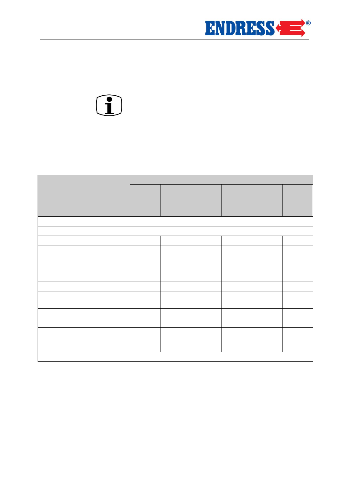
The following servicing work must be carried out in accordance with the corresponding periods.
Servicing work
Intervals in operating hours [h]
after
8 h
every
8 h
/
daily
every
25 h /
yearly
every
50 h /
yearly
every
100 h /
yearly
yearly
Check electrical safety
before each operation
Check oil level
before each operation
Change oil
X
(X)1)
Clean air filter
(X)2)
Clean area around exhaust
silencer, linkage and springs
X
Change spark-plugs
X
Change fuel filter
(X)3)
Check fitting of screws, nuts
and bolts
X
Check idle speed
(X)4)
Check valve clearance
(X)4)
Check condition and leak
tightness of fuel lines and
connections.
X
Clean combustion chamber
every 500h)4)
Tab. 5.1: Servicing plan for power generator
1) Every 25 h for operation under heavy loads or high ambient tempera-
tures.
2) Clean often in very dusty conditions or where there are high accumula-
tions of foreign matter or during longer periods of use in long dry grass.
3) Where applicable
4) To be done by an Endress-Service-Station.
Page 39

Servicing the Power Generator
Servicing work
39
5.2 Servicing work
Servicing work should only be carried out by personnel qualified for this purpose.
All the works listed in the service plan are to be carried out in
accordance with the operating and service instructions for
the motor.
We recommend that these works be carried out by an authorised ENDRESS Service station.
5.3 Checking Electrical Safety
The electrical safety may only be checked by personnel authorised for this task.
The electrical safety must be checked in accordance with the
applicable German VDE regulations, EN and DIN norms and
the special Prevention of Accident Regulations BGV A3 in
the relevant applicable version.
Page 40
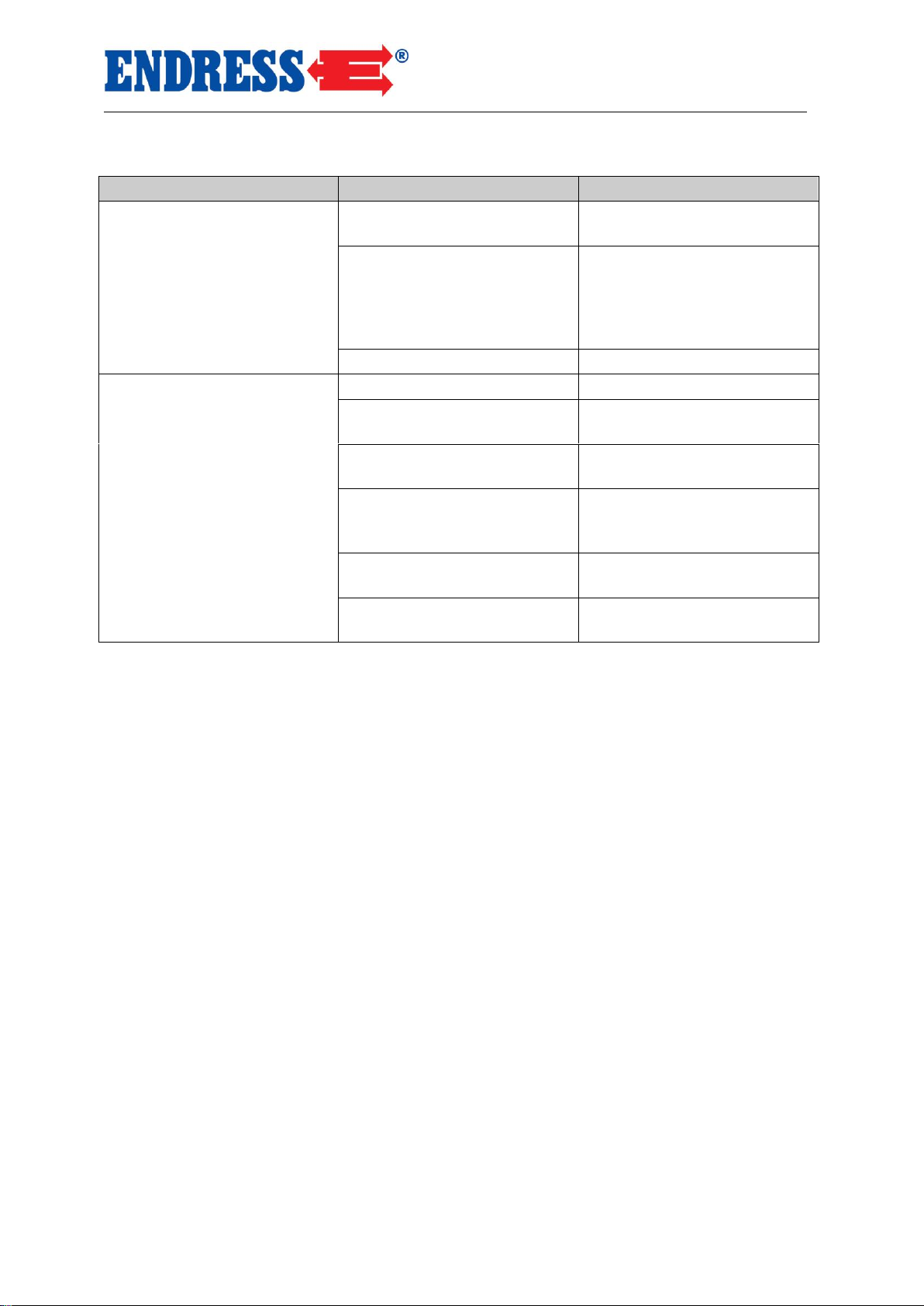
Trouble Shooting
40
6 Trouble Shooting
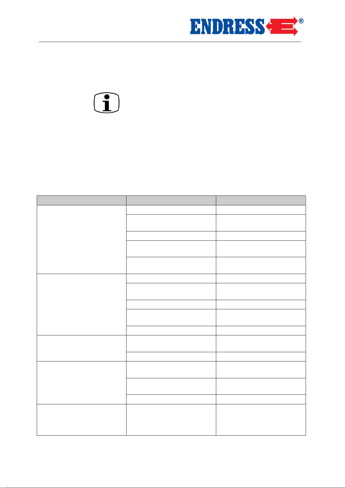
This section describes how qualified personnel can repair
problems that arise during operating.
Each problem is described with the possible cause and the
applicable method by which it can be remedied.
If a problem listed in the following table cannot be repaired,
the responsible personnel must switch off the power generator immediately and inform the responsible authorised service personnel.
*It is recommended that a service station be consulted
for checks or repairs here
Fault
Possible cause
Remedy
No power from the
socket
Engine speed too low
*Adjust engine speed
Open circuit or short-circuited
wiring
Check load
Defective Condenser/AVR
*Replace Condenser/AVR
Rotor or stator winding
open/short-circuited
*Test winding resistance, if
required replace the winding
Circuit breaker in OFF position
Push circuit breaker to ON
position
Low output voltage with no
load
Engine speed too low
*Adjust engine speed
Rectifier
*Test rectifier, replace if required
Defective Condenser/AVR
*Replace Condenser/AVR
Rotor or stator winding
open/short-circuited
* Test winding resistance, if
required replace the winding
Generator not magnetised
*Re-magnetise generator
High output voltage with no
load
Engine speed too high
* Adjust engine speed
Engine speed too low
*Adjust engine speed
Low output voltage with load
Rectifier
*Test rectifier, replace if required
Machine speed too low at full
load
*Adjust engine speed
Too much load applied
Reduce applied load
Irregular output voltage
Irregular load applied
Disconnect complete load,
then reconnect individually in
order to determine which is
causing the irregular function.
Page 41
Trouble Shooting
41
Fault
Possible cause
Remedy
Noisy operation
Loose generator or machine
screw
Tighten all mounting parts
Short-circuit in generator
field/load
*Test winding resistance, replace field winding, check
load appliances if required.
Replace defective load appliances.
Defective bearing
*Replace bearing.
Engine will not start
No fuel
Check fuel
Fuel valve in OFF position
Push fuel valve to open position ON
Rocker switch in OFF position
Push rocker switch to ON
position
Spark plug connector is dirty
or loose
Clean spark-plug connector.
Adjust aperture, replace if
necessary
Spark plug is dirty
Clean spark plug, replace if
necessary
Pilot light illuminated when
starting → oil level too low
Check oil level, fill with oil if
required
Tab. 6.1: Operational problems of the power generator
* It is recommended that a service station be consulted
for checks or repairs here
Page 42
Technical Data
42
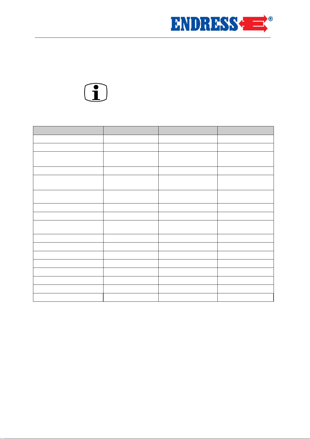
7 Technical Data
This section contains technical information on the operation
of the power generator.
Designation
Model
ESE 306 HS-GT
ESE 606 HS-GT
ESE 606 HS-GT ES
Generator (AVR)
synchronous
synchronous
Synchronous
Frequency / protection
class
50 Hz / IP 23
50 Hz / IP 23
50 Hz / IP 23
Nominal voltage
230 V 1~
230 V 1~
230 V 1~
Max. output power (LTP)
VA
2800
6300
6300
Continuous rating (PRPG1)Watts
2500
5800
5800
Power factor rating cos/(phi)
1 1 1
Phasing
Single phase
Single phase
Single phase
Engine type
1-cylinder 4-cycle air
cooled OHV
1-cylinder 4-cycle air
cooled OHV
1-cylinder 4-cycle air
cooled OHV
Capacity in cm³
196
389
389
Maximum power in kW
3.8
8.2
8.2
Tank capacity (litres)
20
30
30
Length in mm
640
786
786
Width in mm
475
570
570
Height in mm
526
600
600
Weight kg
49
85
92
Motor oil quantity
0.6 litre
1.1 litre
1.1 litre
Tab. 7.1: Power generator specifications
Technical data
* Measured at a distance of 1m and a height of 1.6m in accordance with ISO 3744 (Part 10)
** Measured in accordance with ISO 3744 (Part 10)
Page 43
Trouble Shooting
43
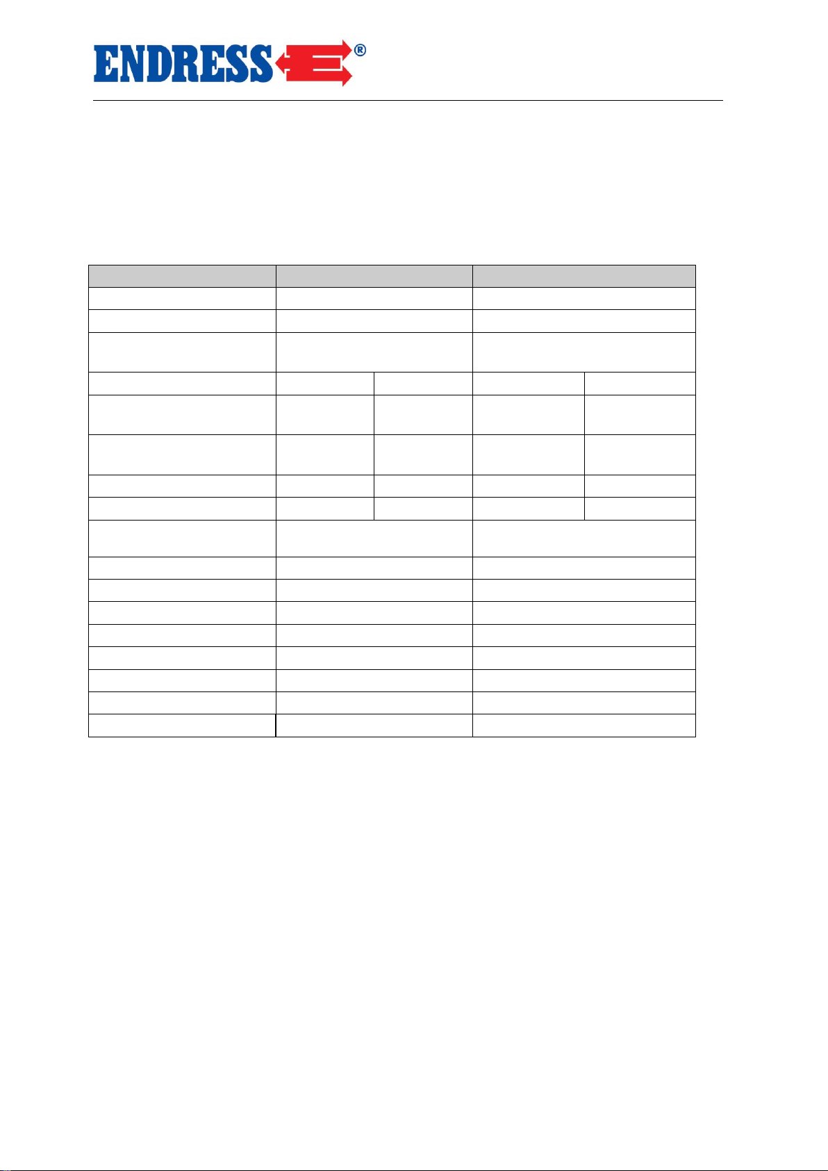
Designation
Model
ESE 606 DHS-GT
ESE 606 DHS-GT ES
Generator (AVR)
synchronous
Synchronous
Frequency / protection
class
50 Hz / IP 23
50 Hz / IP 23
Nominal voltage
230 V 1~
400 V 3~
230 V 1~
400 V 3~
Max. output power (LTP)
VA
4200
7500
4200
7500
Continuous power (PRPG1) in watts
3700
5600
3700
5600
Power factor rating cos/(phi)
1
0.8 1 0.8
Phasing
Single phase
Three phase
Single phase
Three phase
Engine type
1-cylinder 4-cycle air cooled
OHV
1-cylinder 4-cycle air cooled OHV
Capacity in cm³
389
389
Maximum power in kW
8.2
8.2
Tank capacity (litres)
30
30
Length in mm
786
786
Width in mm
570
570
Height in mm
600
600
Weight kg
90
97
Motor oil quantity
1.1 litre
1.1 litre
Tab. 7.2: Power generator specifications
* Measured at a distance of 1m and a height of 1.6m in accordance with ISO 3744 (Part 10)
** Measured in accordance with ISO 3744 (Part 10)
Page 44
Technical Data
44
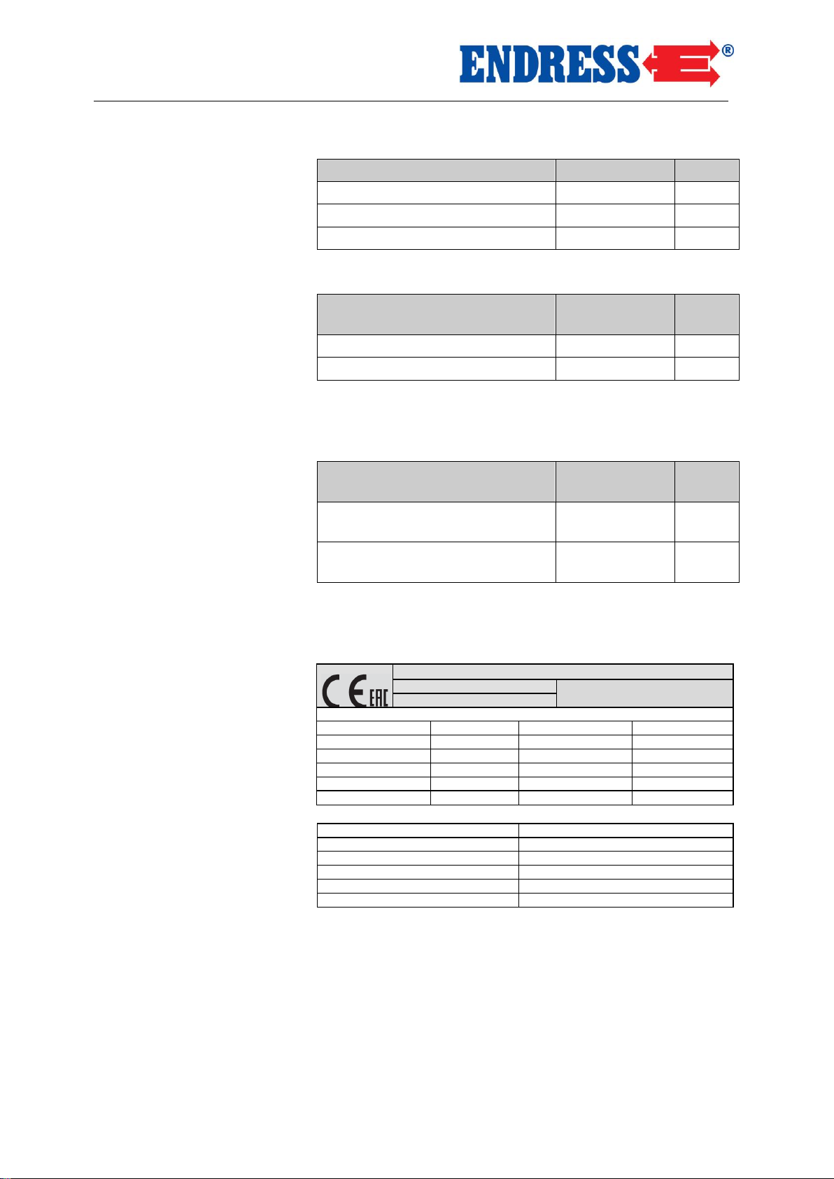
Description
Value
Unit
set up height about sea-level
< 100
[m]
temperature
< 25
[°C]
relative humidity
< 30
[%]
Tab. 7.3: Ambient conditions for the power generator
Reduction in output
each addition-
al
Unit
1 %
100
[m]
4 %
10
[°C]
Tab. 7.4: Reduced output of the power generator dependent on the
ambient conditions
Circuit
max. circuit
length
Unit
1.5 mm2 HO 7 RN-F or equivalent
60
[m]
2.5 mm2 HO 7 RN-F or equivalent
100
[m]
Tab. 7.5: Maximum circuit length of the distribution network based on
diameter of wiring
ENDRESS Elektrogerätebau GmbH
ESE 606 HS
Neckartenzlinger Straße 39
Generating set ISO 8528
D-72658 Bempflingen, Germany
Pr (PRP-G1)
5.8 kW
S/N
112211/ 00001
cos r
1.0
fr
50 Hz
Ur 1~
230 V
Ir
25.2A
IP
23
hmax
1000m
Tmax
40°C
Class
G1
Mfg
2016 m 85 kg
Rated power in kW
Serial number
Rated power factor
Rated frequency in Hertz
Rated voltage in volts
Rated current in amps
International protection class
Maximum set up height in metres
Maximum ambient temperature
Type class
Year of manufacture
Weight in kilograms
Ambient conditions
Reduced output
Distribution network
Explanation of type plate
Page 45

Technical Data
8 Terms of Warranty
Please consult the dealership where you purchased our product in the event of a claim under the
warranty or for replacement parts.
Please note that the following documentation must, in every case, accompany the defective appliance:
Purchase documentation (till receipt or invoice)
Description of the defect that has arisen
Service – Hotline
Telephone:+49(0)7123-9737-44
EMail: [email protected]
ENDRESS Elektrogerätebau GmbH●Neckartenzlinger Straße 39●D 72658 Bempflingen
Telephone: +49-(0)-7123-9737-0●Telefax: +49-(0)-7123-9737-10●EMail:[email protected]●www.endress-generators.de
45
Page 46
Notes
Accessories:
Wheelset can be ordered optional
Make everything easier by using the correct gearing set for your power generator:
Available as accesssories for the following models:
ESE 306 HS-GT Order No. 161 032
46
 Loading...