

Page 1

The Light pack contains:
The following tools may be required:
EL- 40062 / EL- 40063 PIR wall fittings.
Safety Warnings
INSTRUCTION MANUAL
This product is only suitable for connection to a 240V~50Hz supply.
It is recommended that this light is installed by a qualified electrician in accordance with current IEE Wiring
Regulations and local Building Regulations.
The light fitting should be connected to a lighting circuit protected by a 5 amp fuse (or a 6 amp miniature
circuit breaker).
This light has an IP44 (splash proof) rating suitable for use outdoors.
For optimum detection range a mounting height of 1.8M to 2.5M metres is recommended. Do not mount where
the PIR can be activated by heat sources such as central heating vents, animals, traffic etc.
Run supply wire from a 5-amp electrical supply using double insulated 3-core cable of type H05RN-F 1.0mm
(not supplied) to selected site, ensuring it is adequately protected through the full length of the cable run, it
must come out of the mounting surface in line with the entry to the fitting.
Except where installed in a conduit or duct , which provides equivalent protection against mechanical damage,
a cable buried in the ground shall incorporate an earthed armour or metal sheath or both, suitable for use as a
protective conductor, or be of insulated concentric construction. Buried cables shall be marked by cable
covers or a suitable marking tape. Buried conduits and ducts shall be suitably identified. Buried cables,
conduits and ducts shall be at a sufficient depth to avoid being damaged by any reasonably foreseeable
disturbance of the ground.
This product contains breakable parts – be careful during handling and maintenance to avoid breakage.
The bulb, body and lid cover can become hot in use. Switch off and allow 10 minutes to cool before cleaning
(using a dry cloth only – do not use liquid or abrasive cleaners).
If any part of the bulb housing is broken or cracked then it must be replaced immediately to preserve the water
ingress protection, please consult your retailer. This is represented by the symbol
If any modification is made it will invalidate the warranty and may render the product unsafe.
Before you start
Please read these instructions carefully before fitting your new light and retain for reference.
Switch off the mains supply and remove the appropriate fuse or switch off the appropriate circuit breaker
before commencing installation.
Ensure that no one else has access that would enable the supply to be inadvertently reconnected.
Check the packaging and make sure that you have all the required parts.
Follow each assembly step in order to prevent incorrect assembly – make sure the unit is the correct WAY UP.
Make sure all screws / nuts, including electrical connections etc are fully tightened before use.
DO NOT CONNECT THIS PRODUCT TO A DIMMER SWITCH AND DO NOT USE COMPACT FLUORESCENT
LAMPS – FOR USE WITH STANDARD TUNGSTEN LAMPS ONLY.
Wall light with integral PIR detector (with fitted
photocell)
Selection of cross and flat head screwdrivers.
Electric drill and assorted drill bits.
Wire strippers.
Electrical insulation tape.
2
Page 2
Assembly / user instructions
Endon Lighting
20150309
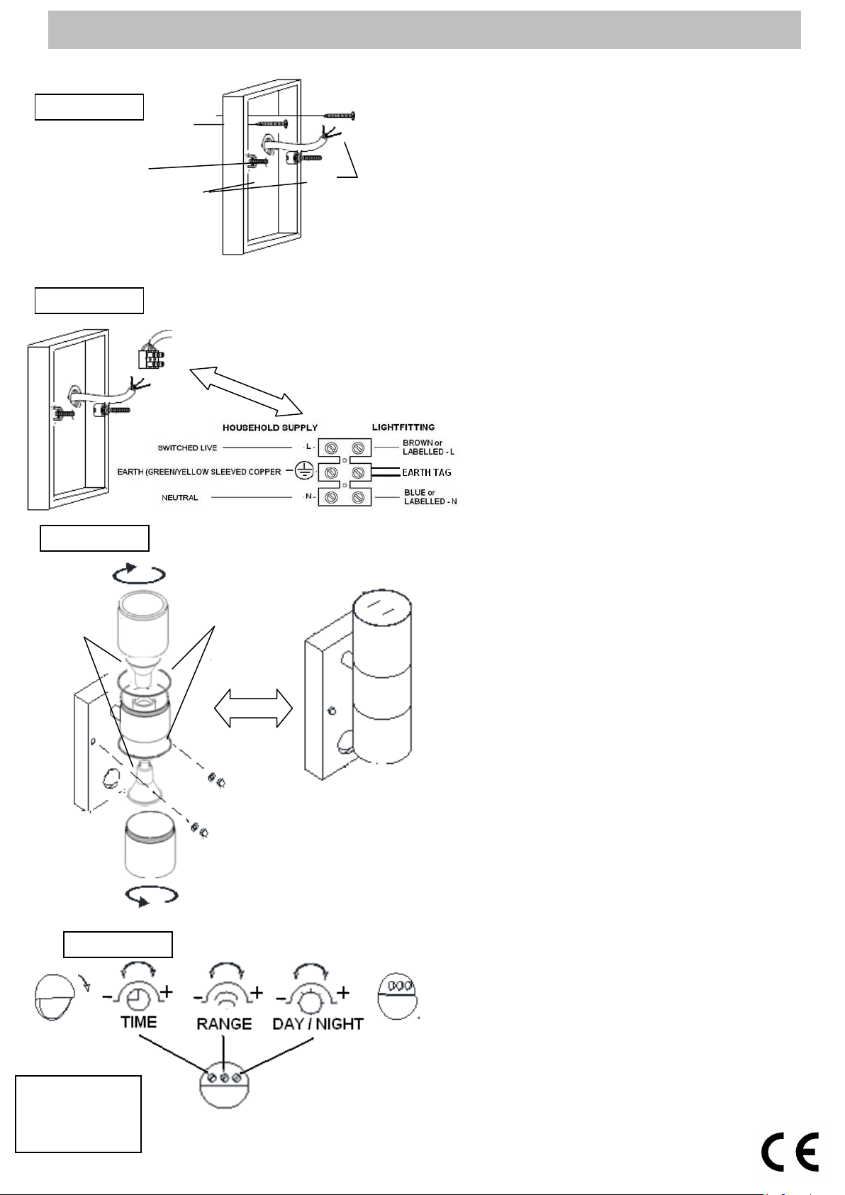
Diagram A
Diagram B
Diagram C
1. Determine the position of your light fitting taking into
Diagram D
Fixing screws
Grommet
Threaded nuts
Gu10
bulbs
N210 101
These assembly diagrams are intended as a guide – if in doubt consult a qualified electrician.
Model EL-40062 is shown here but the same general instruction applies to model EL-40063.
Threaded bolts
LS9 0SE
Seals
NOTE:-
account the entry position of the cable and the
ARROW indicating which WAY UP the base is to be
fitted – this is so that the drain hole is at the lowest
point on the fitting. Make sure there is sufficient cable
coming out of the wall to connect to the terminal
block. Ensure that the mounting surface is solid,
preferably a brick or block wall and ensure that there
are no other cables or pipes beneath the surface.
2. Diagram A. Fit the 2 threaded posts in the back plate
and bring the mains cable through the rubber
grommet then use the back plate as a template and
mark the 2 fixings holes, making sure the back plate
is correctly aligned so that the threaded bolts are
horizontal. Use appropriate fixings to secure the back
plate to the wall.
Diagram B. Connect the house wiring to the internal
3.
terminal block. The cable entry grommet must be
securely in place to ensure that the water ingress
protection is maintained. NOTE: This is a Class I
fitting and must be earthed. Connect the incoming
mains as per the diagram.
4. Diagram C. Fit the terminal block onto the post in the
back plate and then fit the front frame over the 2
threaded bolts in the back plate and secure with the 2
threaded nuts. Take care not to trap or strain the
internal cables.
5. Fit the appropriate bulbs into the lamp holders
NOTE: Never fit bulbs of a higher wattage than
specified on the label (as this may cause
overheating and damage the fitting). Secure the
lids- making sure the seals are in place.
6. Diagram D. To Test the Lantern. Turn on the
power. To test the PIR unit in daylight, Pull the lens
cover down – to expose the dials- then turn the timer
dial (with clock) gently fully anti-clockwise (towards
the -) and turn the Day / Night dial gently fully
clockwise (towards the +). Lift the lens cover and
activate the PIR by covering the PIR lens with your
hand. The unit will light and should stay on for
approximately 5-10 seconds then go off. It will remain
off until the light level drops.
7. To adjust Time On. By adjusting the timer dial the
unit will stay on (once activated) from 5 seconds (fully
anti-clockwise) to 5 minutes (Fully clockwise)
To adjust range level. By adjusting the Range level
dial the unit will activate from 4 metres (fully
anticlockwise) to 8 metres (fully clockwise).The angle
of detection is approximately 90.
To adjust the light level. By adjusting the Light
level dial the unit will activate either in daylight (fully
anticlockwise) or at night (fully clockwise).
1. All time on values are approximate.
2. After adjustment, make sure the lens cover is
lifted up to expose the detector lens.
3. This unit does NOT have an override function.
 Loading...