

Endon Muni-CH, Muni-CO Instruction Manual

1
The Light pack contains:
Light fitting with decorative glass balls.
Terminal connection block(s).
The following tools may be required:
Selection of cross and flat head screwdrivers.
Electric drill and assorted drill bits.
Wire strippers.
Electrical insulation tape.
INSTRUCTION MANUAL
These products are only suitable for connection to a 240V~50Hz supply in accordance with current
IEE wiring Regulations and should be installed in accordance to local UK Building Regulations and
are for Domestic ceiling use only and not suitable for a Bathroom location.
The light fitting should be connected to a lighting circuit protected by a 5 amp fuse (or a 6 amp
miniature circuit breaker).
If in doubt we recommend you contact a qualified electrician. Before installing your light fitting
always:
Switch off the mains supply and remove the appropriate fuse or switch off the appropriate circuit
breaker before commencing installation.
Ensure that no one else has access that would enable the supply to be inadvertently reconnected.
This product contains glass parts – be careful during handling and maintenance to avoid breakage.
This fitting uses none-replaceable LED`s. As with all LED`s we recommend that you do not stare
directly into the light beam.
Clean with a dry cloth only. Do not use liquid or abrasive cleaners on this product.
This fitting is heavy / awkward and you may require assistance in connecting it to the supply and
securing it to the mounting surface. When fixing to the mounting surface ensure that the fixings
used are appropriate for the mounting surface on which they are being used.
If any modification is made it will invalidate the warranty and may render the product unsafe.
Before you start
Please read these instructions carefully before fitting your new light and retain for reference.
Make sure that there are no pipes or cables beneath the mounting surface.
Check the packaging and make sure that you have all the required parts.
Follow each assembly step in order to prevent incorrect assembly.
Make sure all screws / nuts, including electrical connections etc are fully tightened before use.
This type of Light Fitting cannot be connected to a Dimmer.
Muni – CH and Muni – CO (Chrome and Copper LED Pendants).
Safety Warnings
2
Assembly/ User Instructions
These assembly diagrams are intended as a guide – if in doubt consult a qualified electrician.
Endon
LS9 0SE
20150903
B640 04v3
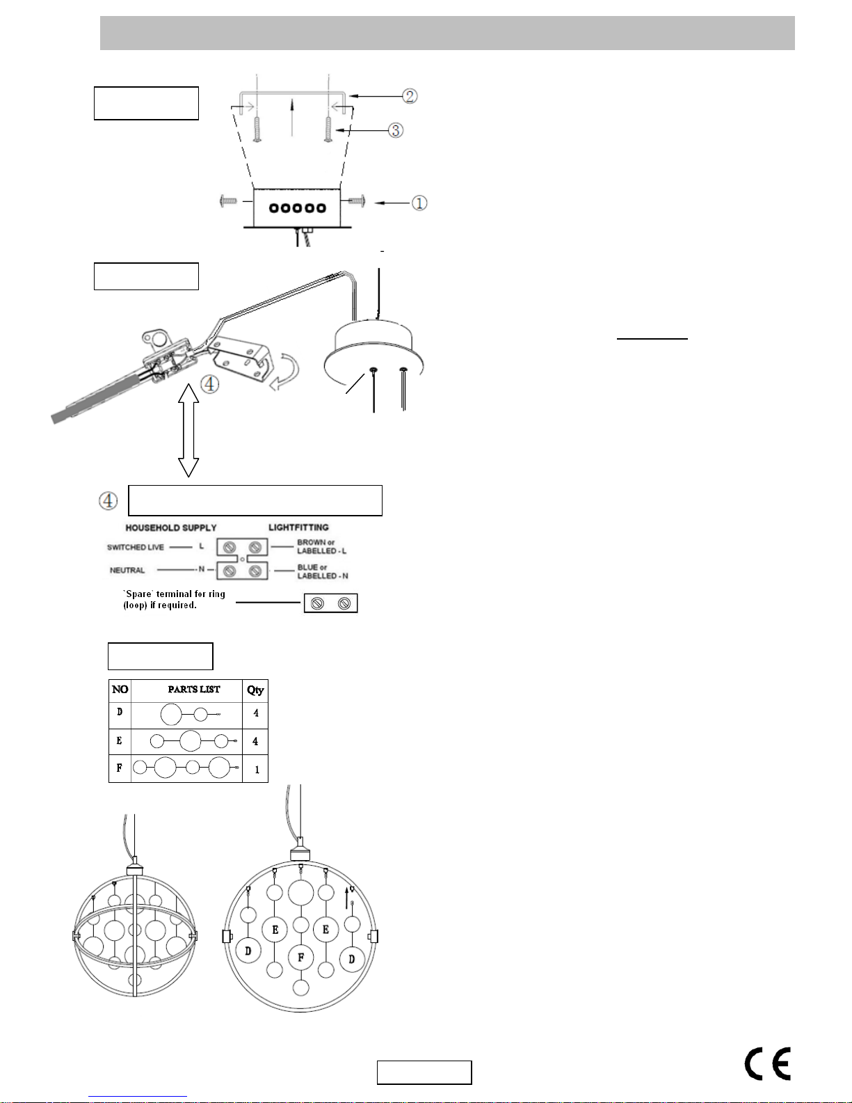
Diagram A
1. Decide on the position of the light fitting / or remove
existing light fitting. Take a note of the position of the
electrical connections. Ensure there is a solid mounting
surface, preferably a wooden joist or joist bridge to
support the weight of the light fitting.
2. Diagram A. Remove the fixing bracket, by undoing the
2 side screws (1), retain these for re-use.
3. Use the fixing bracket (2) as a template to mark the
screw holes, mark the screw holes and secure to
the ceiling with the screws (3) supplied.
4. Diagram B. The length of the `drop` may be reduced
by shortening the cable / support wire. If you want to
reduce the overall length of the fitting it is essential that
this is done before the fitting is mounted to the ceiling
and / or connected to the mains supply. To do this,
shorten the length of the s upport wire
by pushing up
the centre of the support mechanism (which acts as a
clutch) and pull the wire up through and into the ceiling
cup. When you reach the desired overall length release
the centre clutch – this will then grip the support wire.
We recommend that the minimum distance between
the ceiling cup and the top of the fitting is 100mm. The
LV cable can be loosely curved around the support
wire. NOTE: The electric cable must always be
longer than the support wire to prevent strain being
placed on the cable.
5. Support your fitting and connect the house wiring to the
terminal block (4) – see also details of terminal wiring.
NOTE: This is a Class II fitting and must not be
earthed. If you have any earth cables make sure
that they are connected to each other – to maintain
earth continuity throughout your property – and
wrap the earth terminal and connections in 2 layers
of good quality insulation tape and keep them away
from the terminal connections of the fitting. Open
the terminal block box and take out the long tailed
grommet, sliding it up the house supply cable. Cut and
strip the cable and connect it to the terminal block as
shown. Close the box. The additional single terminal
block connector is used for the “loop” wires of the “Ring
Circuit”. There may be more than one set of cables in
the “loop” connections. This additional connector must
be wrapped in 2 layers of good quality insulation tape to
prevent the conductors touching the main terminal
block connections or the metal of the fitting. If there is
a “Ring Circuit” and you do not understand the
connections you must consult an electrician.
6. Secure the fitting back onto the fixing bracket with the 2
side screws (1), removed in 2 above. Make sure that
all the internal cables and connections are inside the
Ceiling cup taking care not to trap or strain the internal
cables.
7. Diagram C. Carefully hang the decorative glass ball
assemblies onto the frame according to the diagram.
8. Turn on the power and test.
Details of terminal wiring.
Diagram B
Diagram C
Support wire
clutch
mechanism
 Loading...