

Elite2
EN Instructions for Use 2
FR Instructions D’Utilisation 14
DE Gebrauchsanweisung 26
IT Istruzioni per L’Uso 39
ES Instrucciones de Uso 51
EL24L1–EL30R9
EL24L1D–EL30R9D
EN
2
938223/13-0717
User weight
Foot spring
set
Impact
Activity
44–52
(100-115)
53–59
(116-130)
60–68
(131-150)
69–77
(151-170)
78–88
(171-195)
89–100
(196-220)
101-116
(221-255)
117-130
(256-285)
131-147
(286-325)
148-166
(326-365)
kg
(lb)
Low 3 1 1 2 3 4 5 6 7 8 9
Mod 4 1 2 3 4 5 6 7 8 9
High 4 2 3 4 5 6 7 8 9
Important:
For higher impact users, do not exceed the
weight limit for individual springs.
Low Daily walking and occasional sports such
as golf and hiking
Moderate Aggressive walking, frequent or daily
sports such as jogging
High Daily activities such as distance running,
climbing, lifting and carrying heavy
objects for vocational purposes
Application
These instructions for use are for the practitioner.
The term device is used throughout these instructions for use to refer to Elite2.
This device is to be used exclusively as part of a lower limb prosthesis.
A high-energy-return foot. The independent heel and toe springs provide axial deection. The
split toe provides good ground compliance.
This device is recommended for users that have the potential to achieve Activity Level 3 or 4. Of
course there are exceptions and in our recommendation we want to allow for unique, individual
circumstances and any such decision should be made with sound and thorough justication.
Appropriate footwear must be worn to avoid the risk of slipping in
wet environments.
Contra-indications
This device might not be suitable for Activity Level 1 individuals or for competitive sports events,
as these types of users will be better served by a specially designed prosthesis optimized for their
needs.
Intended for a single user.
Ensure that the user has understood all instructions for use, drawing particular attention to the
section regarding maintenance.
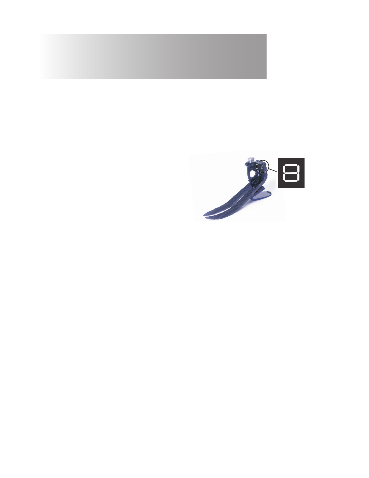
1 Description and Purpose
Spring set selection
3
938223/13-0717
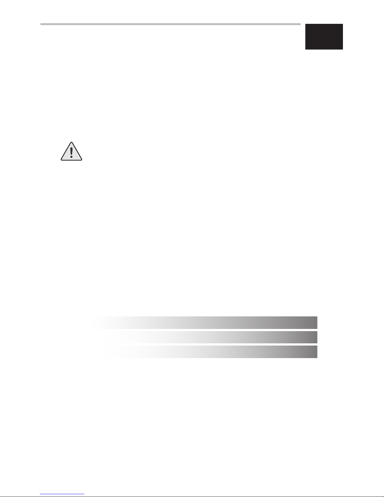
When tted with springs, cover appropriate
lines on carrier with permanent black marker
to leave spring set number showing.
Note:
If in doubt choosing between two categories, choose the higher rate spring set.
Foot Spring set recommendations shown are for trans-tibial users.
For trans-femoral users we suggest selecting a spring set one category lower,
refer to tting advice Section 7 to ensure satisfactory function and range of movement
Has the ability or potential for ambulation with variable cadence.
Typical of the community ambulator who has the ability to traverse most
environmental barriers and may have vocational, therapeutic, or exercise activity
that demands prosthetic utilization beyond simple locomotion.
Activity Level 3
4
938223/13-0717
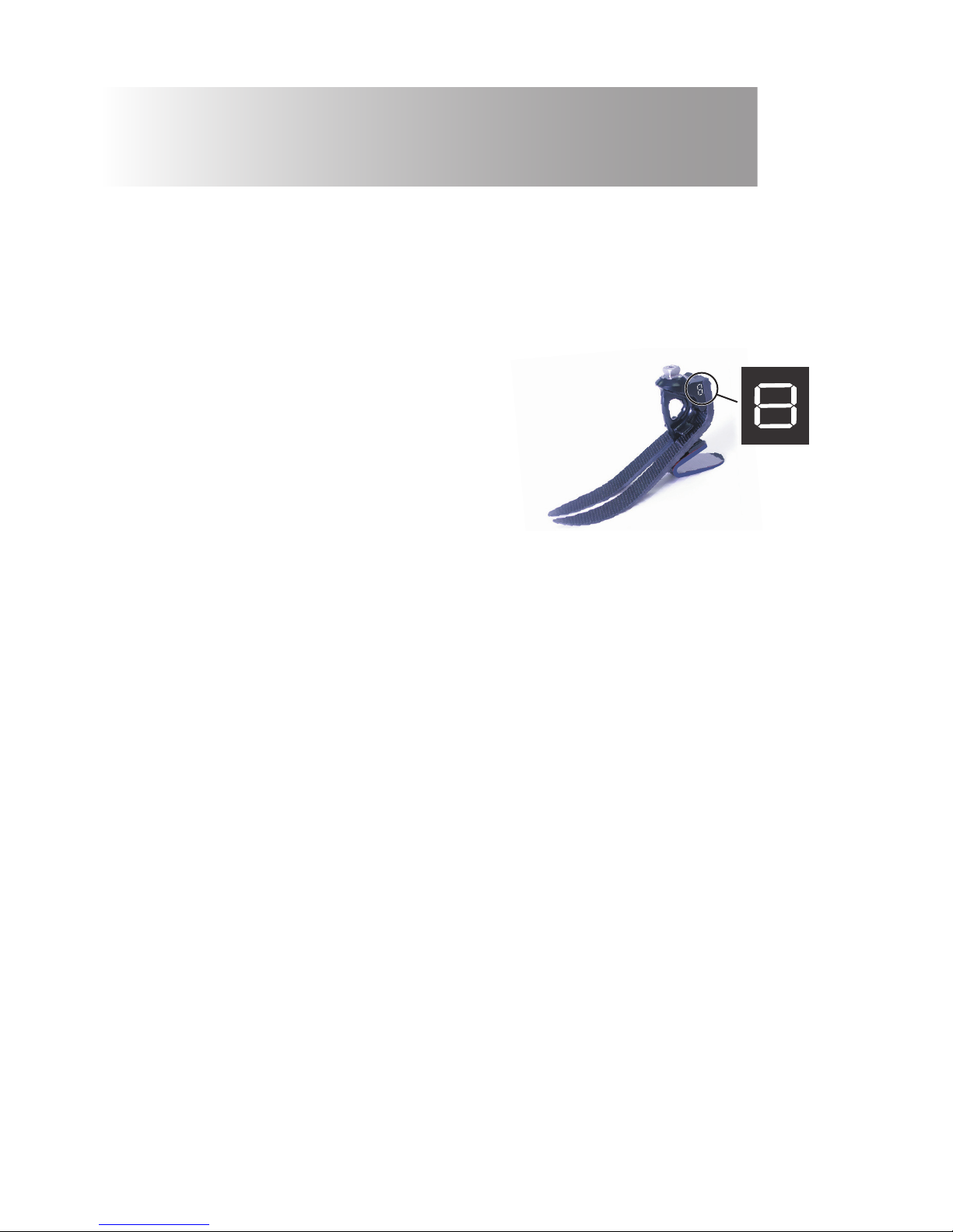
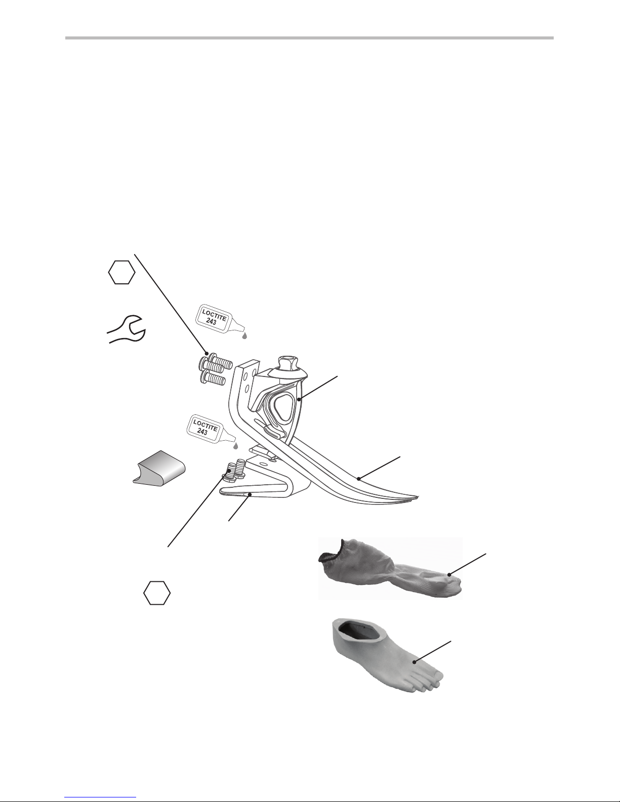
Principal parts:
• Carrier Assembly (aluminum/St. Stl./titanium)
• Heel & Toe Springs (e-Carbon)
• Spring Attachment Screws (titanium)
• Glide Sock (UHM PE)
• Foot Shell (PU)
2 Construction
Glide
Sock
Foot
Shell
Toe Spring
Carrier
Heel
Spring
Heel Spring
Screws
Toe Spring
Screw
4
15 Nm
13A/F
25 Nm
(cat 8&9)
4
15 Nm
(cat 1–7)
Heel Wedge
5
938223/13-0717
3 Function
This device comprises an e-carbon toe and independent heel spring.
Heel and toe springs are attached to the carrier using titanium screws. The foot is wrapped in a
UHM PE sock which is in turn surrounded by a PU foot shell.
4 Maintenance
5 Limitations on Use
Maintenance must be carried out by competent personnel.
We recommend the following annual maintenance:
• Remove the foot shell and glide sock, check for damage or wear and replace if necessary.
• Check all screws for tightness, clean and reassemble as necessary.
• Check heel and toe springs for signs of delamination or wear and replace if necessary. Some
minor surface damage may occur after a period of use, this does not aect the function or
strength of the foot.
The user must be handed the user information card supplied, and be advised of the following:
• Any changes in performance of this device must be reported to the practitioner
e.g. reduced energy return or unusual noises.
• The practitioner must also be informed of any changes in body weight and/or activity level.
If this device is used for extreme activity, the maintenance level and interval should be reviewed
and if required advice and technical support sought to plan a new maintenance schedule
dependent upon the frequency and nature of the activity. This should be determined by a local
risk assessment carried out by a suitably qualied individual.
Cleaning
Use a damp cloth and mild soap to clean outside surfaces, do not use aggressive cleansers.
Intended life
A local risk assessment should be carried out based upon activity and usage.
Lifting loads
User weight and activity is governed by the stated limits.
Load carrying by the user should be based on a local risk assessment.
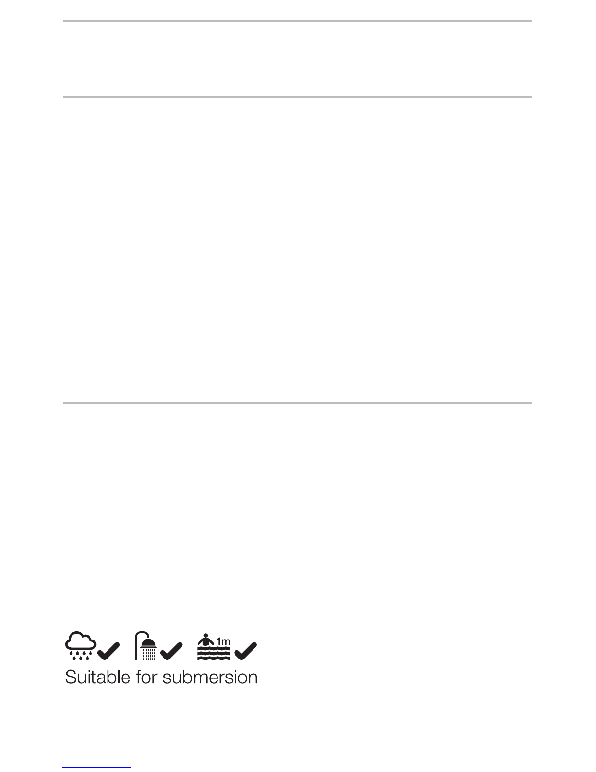
Environment
This device is waterproof to a maximum depth of 1 meter.
Thoroughly rinse this device with fresh water after use in abrasive environments such as those
that may contain sand or grit, for example, to prevent wear or damage to moving parts.
Thoroughly rinse with fresh water after use in salt or chlorinated water.
Foot units must be adequately nished to prevent water ingress into the foot shell where
possible. If water enters the foot shell, it should be inverted and dried before further use.
Exclusively for use between -15 ˚C and 50 ˚C.
We recommend using Endolite products with this device.
0-10mm
½½
6
938223/13-0717
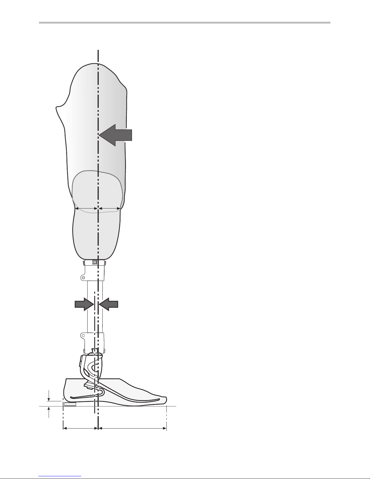
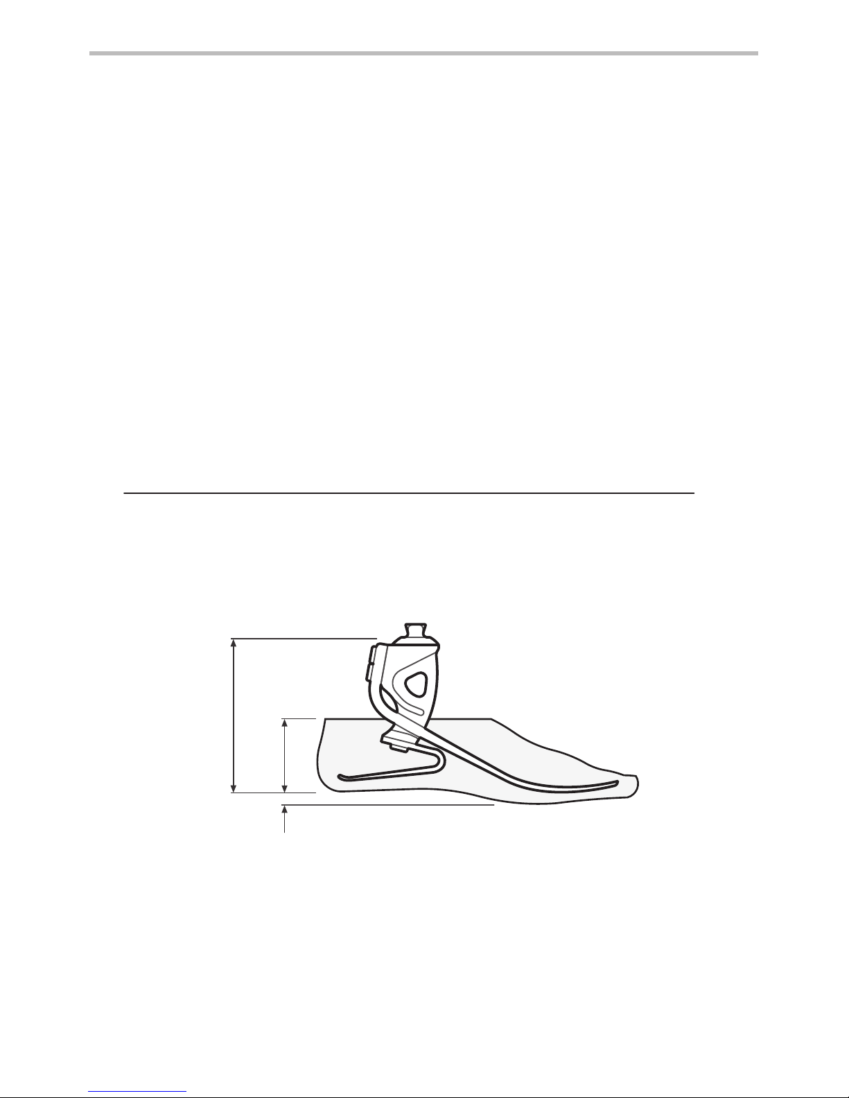
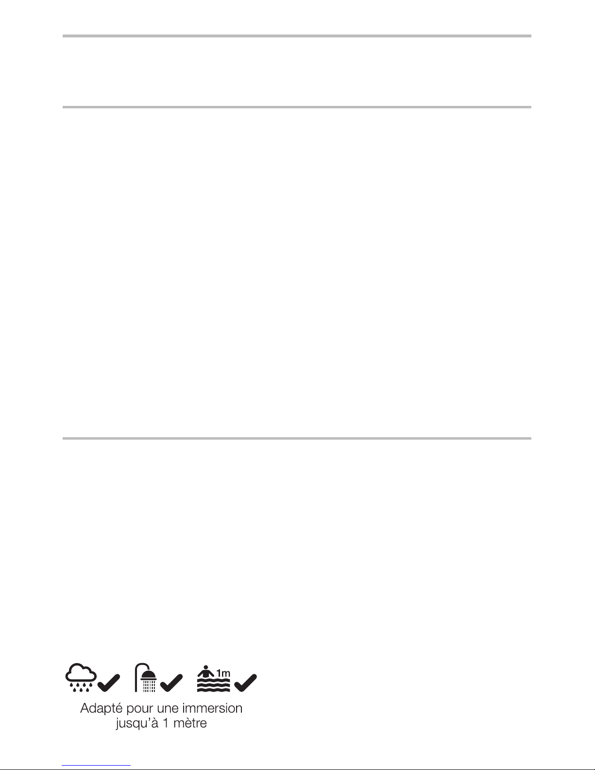
6 Bench Alignment
Static alignment
Setup length
With exion, adduction and abduction
properly accommodated, set the limb length
5 mm longer than the sound side to allow for
compression and deection of the foot springs
during gait. This should be re-assessed once
the dynamic trial commences and the length
adjusted accordingly.
Build line
This should fall 10 mm anterior to the centre
of the pyramid (with heel height properly
accommodated). The socket should be
positioned accordingly.
Dynamic alignment
Coronal plane
Ensure that M-L thrust is minimal by adjusting
relative positions of socket and foot.
Saggital plane
Check for smooth transition from heel strike
to toe-o. Ensure also that when standing the
heel and toe are evenly loaded and that both
are touching the oor.
Trans-femoral alignment
Align trans-femoral components according
to tting instructions supplied with the knee,
keeping the build line relative to the foot as
shown.
Build
Line
Approx.
1/3
2/3
Allow for users
own footwear
*
*

7
938223/13-0717
7 Fitting Advice
Spring sets are supplied as matched pairs i.e. the heel and toe spring are designed to work
together to give smooth progression for most users.
Heel wedge
A heel wedge is supplied with the foot. Fitting the wedge will have the eect of stiening the
heel spring. These can be taped in place for trial. For permanent tting, wedges should be
adhered in place by application of Loctite 424 (926104) between the lower contacting surface of
the heel and the wedge.
Heel stiness
Progression throughout the stance phase should be smooth; heel function is key to this process:
• Too soft a heel or load line excessively posterior will result in sinking at heel strike and
diculty in getting over the toe.
• Too hard a heel or load line excessively anterior will result in a rapid progression through
mid-stance or jarring at heel strike.
Symptoms Remedy
Heel too soft
• Sinking at heel strike
Diculty climbing over the toe
(toe feels too hard)
1. Add heel wedge
2. Move socket anteriorly in relation to
the foot
(excess movement may result in drop
o)
3. If 1 and 2 fail, t a stier spring set
Heel too hard
• Rapid transition from heel strike
through stance phase
Diculty in controlling heel
action, foot jars into mid-stance
• Foot feels too rigid
1. Remove heel wedge (if tted)
2. Move socket posteriorly in relation to
foot
3. If 1 and 2 fail, t softer spring set
Please contact your supplier if it is not possible to achieve a smooth gait after following the advice above.
8
938223/13-0717
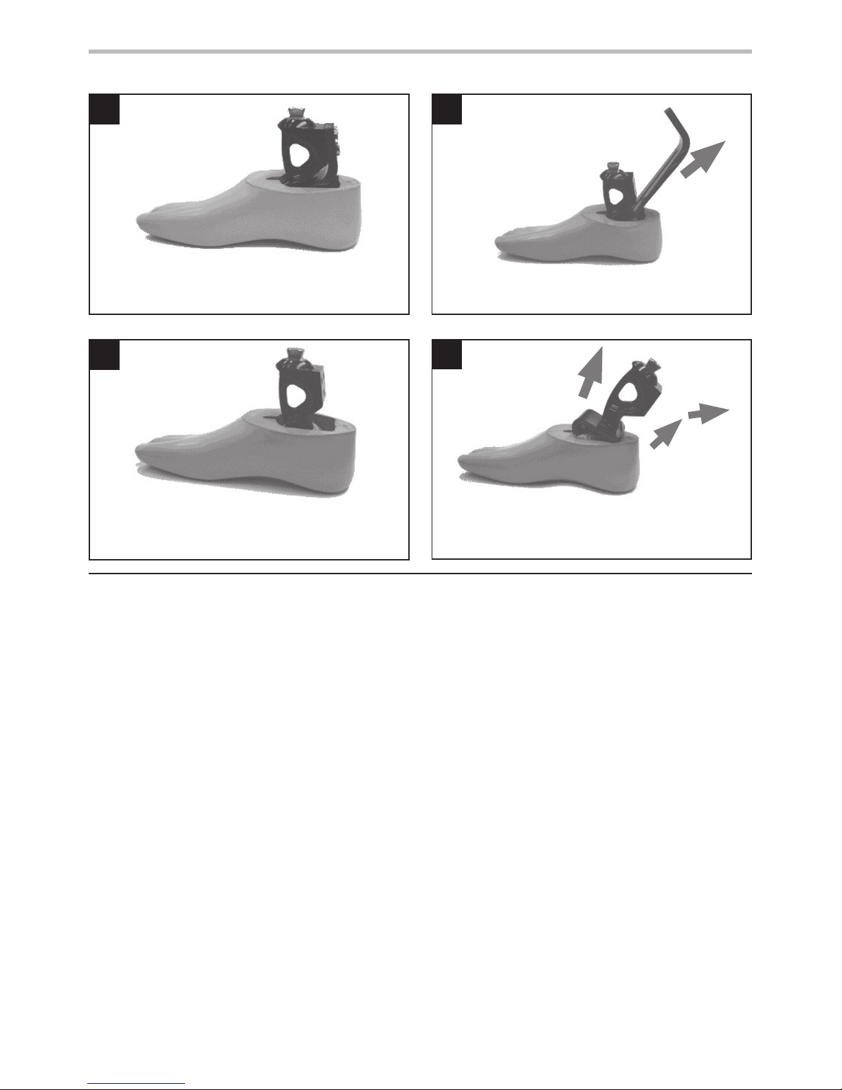
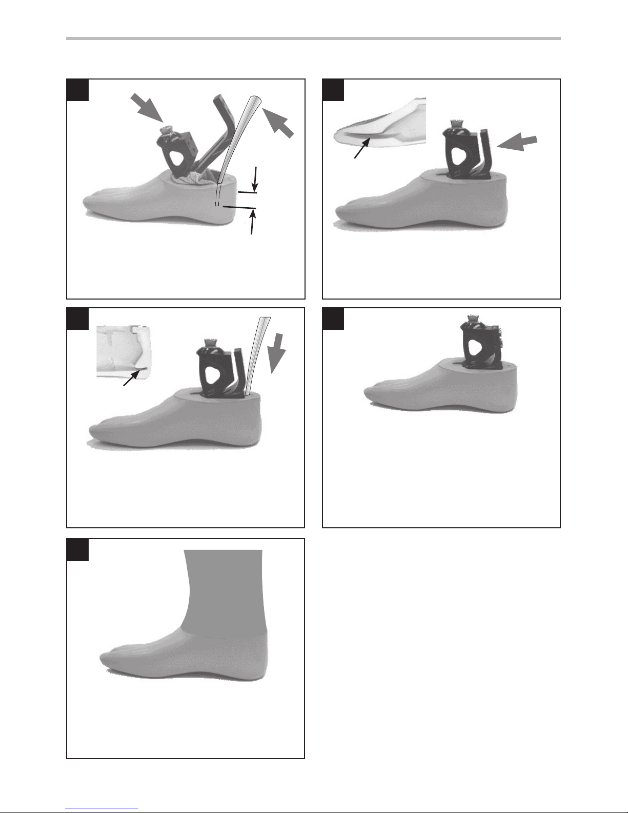
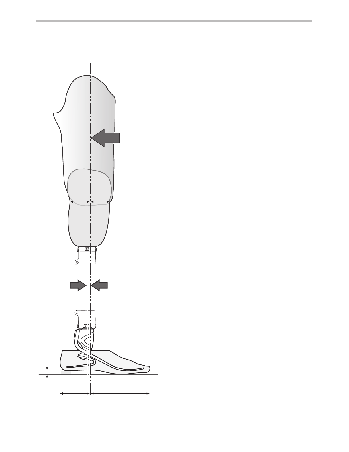
1
Carefully remove, with a knife, any foam cosmesis
that may be adhered to the foot shell.
2
Remove securing screws from the carrier and
pull the toe spring towards the rear of the foot.
3
4
Remove the toe spring to leave the carrier/heel
spring assembly alone inside the foot shell.
Rotate the carrier/heel spring assembly toward
the rear of the foot to dis-engage the spring from
it’s location in the shell.
8 Dis-assembly Instructions
5
2
4
1
3
9
938223/13-0717
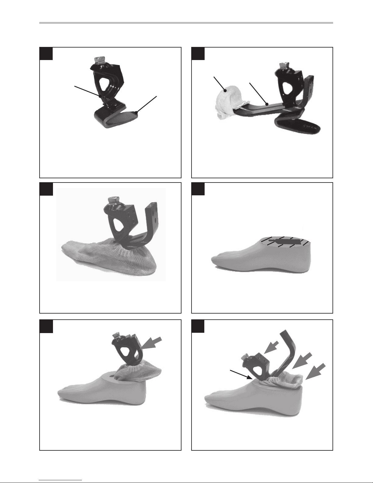
9 Assembly Instructions
Assemble heel spring onto carrier, use Loctite
243 (926012) and torque to 15 Nm. Use special
Allen wrench 940080, Torque spanner adaptor
940081 or 13A/F spanner 940273.
Heel
spring
Carrier
Glide
sock
Unwrap the
glide sock
onto the toe
spring
Unwrap glide sock over heel spring as shown.
Slide toe spring into position on carrier (do
not assemble bolts). Fold the glide sock neatly
around the end of the toe.
If a foam cosmesis is to be tted, roughen top
surface of foot shell to provide ideal bonding
surface.
Push toe spring forward as far as possible.
Slide carrier/heel spring assembly forward into
slot in top of foot shell.
slot in
foot shell
6
11
7
9
8
10
10
938223/13-0717
9 Assembly Instructions (continued)
Slide a metal shoe horn between heel spring and
back of foot shell opening and lever the spring
down into the foot shell.
Push toe spring towards carrier. Ensure glide sock
doesn’t get trapped between the spring and
carrier. Push spring into location in shell.
Press heel spring into location in shell as shown.
Attach the toe spring to the carrier using Loctite
243 (926012) on the bolts.
1. For spring rates 1 to 7 use 4 A/F Allen wrench
and torque to 15 Nm. Do not use external
hex, this is reserved for loosening the bolt, if
required.
2. For spring rates 8 and 9 use 13 A/F spanner
and torque to 25 Nm.
Bond foam cosmesis to top surface of the foot
shell as shown using Thixox adhesive (926204)
or equivalent and shape to suit.
30 mm
below heel
Toe spring
location
in foot shell
heel spring
location slot
11
938223/13-0717
Fitting length
10 Technical Data
Operating and
Storage Temperature Range:
-15 ˚C to 50 ˚C
(5 ˚F to 122 ˚F)
Component Weight (size 26): 395 g ( 14 oz)
Activity Level: 3–4
Maximum User Weight: 166 kg (365 lb)
Proximal Alignment Attachment: Male Pyramid (Endolite)
Range of Adjustment: ±7 ° Angular
Build Height:
(See diagram below)
130 mm
Heel Height: 10 mm
* sizes
24–28 = 70 mm
29–30 = 80 mm
130 mm
10 mm
*
12
938223/13-0717
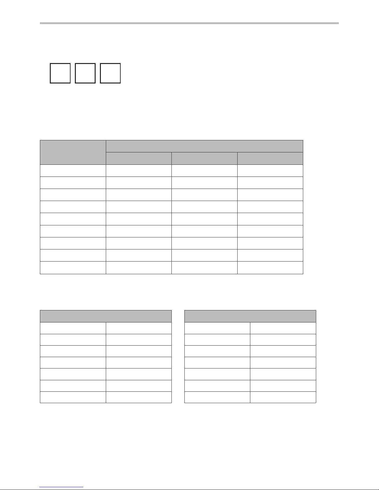
11 Ordering Information
Spring kit
Foot size
24–26 27–28 29–30
Set 1
539710 539719 Special order
Set 2
539711 539720 Special order
Set 3
539712 539721 539730
Set 4
539713 539722 539731
Set 5
539714 539723 539732
Set 6
539715 539724 539733
Set 7
539716 539725 539734
Set 8
539717 539726 539735
Set 9
539718 539727 539736
Spring kit
Foot shell
Left
24L 539005
25L 539007
26L 539009
27L 539011
28L 539013
29L 539015
30L 539017
Right
24R 539006
25R 539008
26R 539010
27R 539012
28R 539014
29R 539016
30R 539018
Glide Sock
One size ts all Part No. 532811
For dark add ‘D’
Available from size 24 to size 30:
EL24L1 to EL30R9
EL24L1D to EL30R9D
Size
Side
Spring Set
Category
Order example
e.g. EL25L3
(add ‘D’ for a dark tone foot shell)
EL
25L
3

13
938223/13-0717
This product meets the requirements of 93/42/EEC guidelines for medical products. This product
has been classied as a Class 1 Product according to the classication criteria outlined in
Appendix IX of the guidelines. The Declaration of Conformity was therefore created by Blatchford
Products Limited with sole responsibility according to Appendix VII of the guidelines.
The manufacturer recommends using the device only under the specied conditions and for the
intended purposes. The device must be maintained according to the instructions for use supplied
with the device. The manufacturer is not liable for damage caused by component combinations
that were not authorized by the manufacturer.
Liability
CE Conformity
Warranty
Blatchford Products Ltd. and ENDOLITE are companies and trademarks of Chas. A. Blatchford and Sons Ltd.
This device is warranted for 36 months - foot shell 12 months - glide sock 3 months.
The user should be aware that changes or modications not expressly approved could void the
warranty, operating licences and exemptions.
See Endolite website for the current full warranty statement.

FR
14
938223/13-0717
Poids de l’utilisateur
Catégories de
jeux de lames
de pied
Impact
Activité
44–52
53–59
60–68
69–77
78–88
89–100
101-116
117-130
131-147
148-166
kg
Faible 3 1 1 2 3 4 5 6 7 8 9
Modéré 4 1 2 3 4 5 6 7 8 9
Fort 4 2 3 4 5 6 7 8 9
Important: pour les utilisateurs à impact
plus fort, ne pas dépasser la limite de poids
de chaque lame.
Faible Marche quotidienne et sport occasionnel
de type golf et randonnée
Modéré Marche aggressive, sports fréquents ou
quotidiens de type course à pied
Fort Activités quotidiennes telles que course
sur longue distance, escalade, levage et
transport d’objets lourds dans un cadre
professionnel
Application :
Ces instructions sont destinées à l’attention de l’orthoprothésiste.
L’Elite2 doit être utilisé dans le cadre d’une prothèse de membre inférieur.
Pied avec forte restitution d’énergie. Le talon indépendant et les ressorts d’orteils procurent une
déexion axiale. L’orteil divisé procure une bonne adhérence au sol.
Cette prothèse est recommandée aux amputés qui ont la possibilité d’atteindre un niveau
d’activité 3 ou 4. Bien évidemment il existe des exceptions et nous conseillons de prendre en
considération les circonstances uniques et personnelles de chacun et de décider après mûre
justication.
Portez des chaussures appropriés pour éviter le risque de chute dans un
environnements humides et glissant
Contre-indications:
Ce dispositif peut ne pas convenir aux individus au niveau d’activité 1 ou aux patients
participant à des manifestations sportives de compétition, car ces utilisateurs seront mieux
servis par une prothèse spéciquement conçue et optimisée pour leurs besoins.
Prévu pour un utilisateur individuel.
Veiller à ce que le patient ait bien compris toutes les instructions d’utilisation et porter une
attention particulière à la section concernant l’entretien.
1 Description et objectif
Choix du jeu de Lames
15
938223/13-0717
Une fois les lames montés, colorier les
lignes appropriées du support au marqueur
permanent noir an d’acher la catégorie du
jeu de lames.
Note:
En cas de doute entre deux catégories de lames, choisir la plus dure.
Les recommandations de jeux de lames repésentés sont pour un patient amputé tibial.
Pour un amputé fémoral nous conseillons de prendre la catégorie en dessous tout en
veillant à respecter les grilles de poids. Se référer à la section 7 de la notice de montage
pour assurer une fonction et une amplitude satisfaisante.
A la capacité ou le potentiel pour se déplacer à des cadences variables.
Typique des patients aptes à gérer la majorité des obstacles
environnementaux et pouvant avoir une activité professionnelle ou
thérapeutique qui exige l’utilisation d’une prothèse au-delà de la
simple locomotion.
Activité 3
16
938223/13-0717
2 Construction
Composants principaux :
• Châssis (aluminium/acier inox/ titane et acier)
• Lames de talon et d’avant pied (E-Carbon)
• Vis de xation de lames (titane et acier)
• Chaussette de protection (UHM PE)
• Enveloppe de pied (PU)
Chaussette de
protection
Enveloppe de
pied
Lame
d’avant pied
Ensemble
support
Lame de talon
Vis de lame
de talon
Vis de lame
d’avant
4
15 Nm
13A/F
25 Nm
(cat 8&9)
4
15 Nm
(cat 1–7)
Cale de talon
17
938223/13-0717
L’Elite2 est constitué d’un orteil en e-carbone et d’une lame de talon indépendante. Les lames de
talon et d’avant-pied sont xées au support par des vis en titane. Le pied est enveloppé dans une
chaussette en PE UHM qui est insérée dans une enveloppe de pied en PU.
Durée de vie prévue :
Une évaluation des risques locaux doit être eectuée en fonction de l’activité et de l’utilisation.
Port de charges :
Le poids et l’activité de l’amputé sont régis par les limites indiquées.
Le port de charges par l’amputé doit être basé sur une évaluation des risques locaux.
Environnement :
Le produit est étanche sur une profondeur maximale de 1 mètre.
Rincez abondamment à l’eau claire après utilisation dans un environnement abrasif comme
ceux susceptibles de contenir du sable ou des gravillons, par exemple, pour prévenir l’usure ou
d’endommager les pièces mobiles;
Rincez abondamment à l’eau claire après utilisation dans de l’eau salée ou dotée de chlore.
Les éléments de pied doivent bénécier d’une nition adéquate pour empêcher l’eau de
pénétrer dans l’enveloppe de pied autant que possible. Si de l’eau pénètre dans l’enveloppe, le
dispositif doit être retourné et séché avant une nouvelle
utilisation.
Exclusivement pour une utilisation de -15°C à 50°C.
On recommande de n’utiliser que les produits Endolite
avec Elite2.
3 Fonction
4 Entretien
5 Limites d’utilisation :
L’entretien doit être eectué par du personnel qualié.
Il est recommandé d’eectuer l’entretien suivant chaque année:
• Retirer l’enveloppe esthétique du pied et la chaussette de protection. Les vérier et s’il existe
des traces de dommage ou d’usure les remplacer.
• Vérier le serrage de toutes les vis, nettoyer et remonter, si nécessaire.
• Contrôler visuellement les lames de talon et d’avant pied pour déceler tous signes de
délamination ou d’usure : les remplacer si nécessaire. Des dégâts mineurs en surface peuvent se
produire après une période d’utilisation, cela n’aecte pas la fonction ou la résistance du pied.
La che d’utilisation doit être remise à l’utilisateur et ce dernier doit être informé de ce qui suit:
• Tout changement des performances de ce dispositif doit être signalé à l’orthoprothésiste.
(Par exemple, une diminution de la restitution d’énergie ou des bruits inhabituels.)
• L’orthoprothésiste doit également être informé de tout changement dans le poids corporel
et / ou le niveau d’activité du patient.
Si ce produit est utilisé pour une activité extrême, l’intervalle et le niveau d’entretien doit être
revu. En fonction de la nature et de la fréquence de cette activité un nouveau calendrier de
suivi devra être établi. Celui-ci pourra être déterminé après une évaluation locale des risques
eectuée par une personne dûment qualiée.
Nettoyage :
Utiliser un chion humide et un savon doux pour nettoyer les surfaces extérieures; n’utiliser pas
de détergent agressif.
0-10mm
½½
Prendre en compte la hauteur de
talon de la chaussure de l’utilisateur
18
938223/13-0717
6 Alignement
Alignement statique
Dénir la hauteur
Une fois la exion, l’aduction et l’abduction
dûment réglées, xer la hauteur de l’appareil
à 5 mm de plus que le membre sain an
depermettre la compression et la détente des
lamesdu pied lors de la marche. Ce réglage
doit êtreréévalué après les tests dynamiques et
lalongueur réajustée en fonction.
Ligne de charge
Celle-ci devrait tomber entre la ligne centrale
dela pyramide et 10 mm plus en avant (le
poids dupatient étant correctement réparti).
L’emboîturedoit être positionnée en fonction.
Alignement dynamique
Plan frontal
Vérier que le mouvement M-L est minimal
enréglant les positions respectives de
l’emboîture etdu pied.
Plan sagital
Vérier que la transition depuis l’attaque du
talon jusqu’a la phase d’élan est souple et
continue. Vérier aussi qu’en position debout,
le poids estégalement réparti entre le talon et
l’avant du pied et que les deux sont en contact
avec le sol.
Alignement fémoral
Aligner les dispositifs fémoraux selon les
instructions de montage fournies avec le
genou, en maintenant l’axe de montage par
rapport à l’Elite2 comme sur le schéma.
Ligne de
charge
Environ
1/3
2/3
*
*

19
938223/13-0717
7 Conseils de réglages
Veuillez contacter le fournisseur si vous n’obtenez pas une démarche souple même en appliquant les conseils
ci-dessus.
Les jeux de lames Elite2 sont fournis par paires, la lame de talon et celle d’avant pied sont
conçus pour fonctionner ensemble an d’assurer à la plupart des personnes amputées un
fonctionnement confortable.
Cale de talon
Une cale de talon est fournie avec le pied. Le montage de la cale durcira la lame de talon.
Elle peut être scotchée en place pour un essai. Le montage dénitif des cales doit se faire par
application de Loctite 424 (926104) entre la surface de contact inférieure du talon et la cale.
Rigidité du talon
La progression lors de la phase d’appui doit être souple ; la fonction du talon est essentielle à ce
processus:
• Un talon trop souple ou une ligne de charge trop en arrière peuvent entraîner un
aaissement du talon et une diculté à passer sur l’avant du pied.
• Un talon trop rigide ou une ligne de charge trop vers l’avant peuvent entraîner un passage
rapide en phase d’appui intermédiaire ou un choc lors de la pose du talon.
Symptômes Remède
Talon trop souple
• Aaissement lors de l’attaque
du talon
• Diculté à passer sur l’avant du
pied (les orteils semblent trop
durs)
1. Translater l’emboîture plus vers l’avant
du pied
(un mouvement excessif peut entraîner
un glissement)
2. Mettre un ensemble de ressort plus dur
3. Si 1 et 2 ne fonctionnent pas, monter un
jeu de lames plus durs
Talon trop dur
• Transition rapide de l’attaque du
talon à la phase d’appui
Diculté à contrôler l’action du
talon, rotation du pied ou marche
en 2 temps
• Le pied semble trop rigide
1. Translater l’emboîture plus vers l’arrière
du pied
2. Mettre une lame plus souple
3. Si 1 et 2 ne fonctionnent pas, monter un
jeu de lames plus mous
20
938223/13-0717
1
2
3
4
8 Instructions de démontage
Enlever soigneusement, avec un couteau, toute
la mousse esthétique qui peut adhérer à l’
enveloppe de pied.
Enlever les vis de xation du support et tirer la
lame d’avant pied vers l’arrière.
Enlever la lame d’avant pied pour laisser
l’ensemble support/lame de talon seul à
l’intérieur de l’enveloppe de pied.
Tourner l’ensemble support/lame de talon vers
l’arrière du pied pour dégager la lame de son
emplacement dans l’enveloppe.

21
938223/13-0717
5
4
2
1
3
9 Instruction de montage
Assembler la lame de talon sur le chassîs, avec de
la Loctite 243(926012) et serrer à 15 Nm. Utiliser
la clé Allen speciale 940080, l’adaptateur 940081
ou 13 A/F 940273.
lame de
talon
support
dérouler la
chaussette de
protection sur la
lame d’avant pied.
Dérouler la chaussette de protection sur la lame
de talon comme illustré.
Faire glisser la lame d’avant pied en place sur le
support (ne pas monter les vis). Plier la chaussette
également autour de l’extrémité de l’avant pied.
En cas de montage d’une mousse esthétique,
dépolir la surface supérieure de l’enveloppe de
pied an de créer une surface de collage idéale.
Pousser la lame d’avant pied vers l’avant aussi
loin que possible.
Faire glisser l’ensemble support/lame de talon
vers l’avant dans son emplacement supérieur de
l’enveloppe de pied.
emplacement
dans
l’enveloppe
de pied
6

22
938223/13-0717
11
7
9
8
10
9 Instruction de montage (suite)
Faire glisser un chausse-pied métallique entre
la lame de talon et l’arrière de l’ouverture
de l’enveloppe de pied puis faire levier pour
enfoncer la lame dans l’esthétique
Pousser la lame d’avant pied vers le support.
Vérier que la chaussette de protection n’est pas
prise entre la lame et le support. Pousser la lame
en place dans l’enveloppe
Presser la lame de talon en place dans
l’enveloppe comme représenté.
Fixer la lame d’avant pied sur le support avec de
la Loctite 243 (926012) sur les vis.
1. Pour les catégories de lames 1 à 7, utiliser une
clé Allen 4 A/F et serrer à 15Nm. Ne pas utiliser
l’hexagone extérieur, il est réservé au desserrage
de la vis, le cas échéant.
2. Pour les catégories de lames 8 à 9, utiliser une
clé 13 A/F et serrer à 25Nm.
Coller la mousse esthétique sur la surface
supérieure de l’enveloppe de pied comme
illustré avec de la colle Thixox (926204) ou un
équivalent et former de façon adéquate.
30 mm
sous
le talon
position de la lame
d’avant pied dans
l’enveloppe de pied
position de la lame d’avant
pied dans l’enveloppe de
pied

23
938223/13-0717
Encombrement
Température de fonctionnement : -15 ˚C à 50 ˚C
Poids du composant (taille 26) : 395 g
Niveau d’activité : 3–4
Poids utilisateur max. : 166 kg
Liaison proximale Pyramide mâle (Endolite)
Plage de réglage : ±7 ° angulaire
Hauteur de construction : 130 mm
Hauteur de talon : 10 mm
10 Données techniques
* tailles
24–28 = 70 mm
29–30 = 80 mm
*
130 mm
10 mm

24
938223/13-0717
11 Informations pour la commande
Catégorie
Pointure
24–26 27–28 29–30
Set 1
539710 539719 spécial
Set 2
539711 539720 spécial
Set 3
539712 539721 539730
Set 4
539713 539722 539731
Set 5
539714 539723 539732
Set 6
539715 539724 539733
Set 7
539716 539725 539734
Set 8
539717 539726 539735
Set 9
539718 539727 539736
Jeux de lames
Enveloppe de pied
Gauche
24L 539005
25L 539007
26L 539009
27L 539011
28L 539013
29L 539015
30L 539017
Droite
24R 539006
25R 539008
26R 539010
27R 539012
28R 539014
29R 539016
30R 539018
Chaussette de protection
Taille unique Pièce N° 532811
Pour nuance foncée ajouter « D »
Existe de la taille 24 à la taille 30 :
EL24L1 à EL30R9
EL24L1D à EL30R9D
ex. EL25L3
(ajouter « D » pour une enveloppe de nuance foncée)
EL
25L
3
Taille
et côté
Catégorie du
jeux de lames
Référence produit :

25
938223/13-0717
Elite2 est garanti - 36 mois - enveloppe de pied 12 mois - chaussette de protection 3 mois.
L’utilisateur doit savoir que les changements ou modications non approuvées annuleront la
garantie, les licences d’utilisation et les exemptions.
Voir le site Endolite pour les conditions de garantie complètes et actualisées.
Blatchford Products Ltd. et ENDOLITE sont des sociétés et des marques commerciales de Chas. A. Blatchford and Sons Ltd.
Responsabilité
Le fabricant recommande de n’utiliser le dispositif que dans les conditions spéciées et
pour les buts prévus. Le dispositif doit être entretenu selon les instructions d’utilisation
qui l’accompagnent. Le fabricant n’est pas responsable des dommages provoqués par des
combinaisons de composants qu’il n’a pas autorisées.
Conformité CE
Ce produit respecte les exigences des directives 93/42/CEE relatives aux produits médicaux. Il a
été classé comme un produit de classe I selon les critères de classication décrits dans l’annexe
IX des directives. La déclaration de conformité a donc été établie par Blatchford Products Limited
sous sa seule responsabilité selon l’annexe VII des directives.
Garantie

DE
26
938223/13-0717
Anwendung:
Diese Gebrauchsanweisung ist für Fachpersonal vorgesehen.
Elite2 ist ausschließlich als Teil einer Prothese der unteren Extremitäten einzusetzen.
Ein Fuß mit hoher Energierückgabe. Die unabhängigen Fersen- und Vorderfußfedern bieten
Axialdeexion. Der zweigeteilte Vorfuß bietet eine gute Bodenhaltung.
Der Fuß wird Amputierten empfohlen, die eventuell Mobilitätsklasse 3 oder 4 erreichen können.
Natürlich gibt es Ausnahmen und wir möchten bei unseren Empfehlungen die einzigartigen,
individuellen Umstände berücksichtigen, denn eine solche Entscheidung sollte stichhaltig sein
und gründlich bedacht werden.
Es muss geeignetes Schuhwerk getragen werden um die Rutschgefahr in
nasser Umgebung zu vermeiden
Indikation/Kontraindikation:
Dieses Produkt ist nicht für Anwender der Mobilitätsklasse 1 und für Leistungssportarten
geeignet, da solche Anwender eine speziell auf ihre Bedürfnisse entwickelte Prothese benutzen
sollten.
Dieser Prothesenfuß ist zum Einsatz an einem Anwender vorgesehen.
Stellen Sie sicher, dass der Anwender die Bedienungsanleitung, und insbesondere die
Wartungsanweisungen verstanden hat.
1 Beschreibung und Verwendungszweck
Federkategorie
Gewicht
Belastung-
skategorien
Mobilität
44–52
53–59
60–68
69–77
78–88
89–100
101-116
117-130
131-147
148-166
kg
Niedrig 3 1 1 2 3 4 5 6 7 8 9
Mittel 4 1 2 3 4 5 6 7 8 9
Hoch 4 2 3 4 5 6 7 8 9
Wichtig: - Bei Amputationspatienten mit hoher
Belastung dürfen die Gewichtsbeschränkungen
für die einzelnen Federn nicht überschritten
werden.
Niedrig Tägliches Spazierengehen und
gelegentliche sportliche Aktivitäten, wie
Golf Spielen oder Wandern
Mittel Aktives und ausdauerndes Gehen,
häuger oder täglicher Sport wie z.B.
Jogging
Hoch Tägliche Aktivitäten wie
Langstreckenlaufen, Klettern oder das
Tragen schwerer Objekte aus beruichen
Gründen
Auswahlschema Federstärken

27
938223/13-0717
Die entsprechende Federauswahl auf dem
Markierungsfeld der ausgewählten Feder, z.B.
mit einem schwarzen Filzstift kennzeichnen, so
dass die Zahl erkennbar ist.
Mobilitätsklassen 3
Der Anwender besitzt die Fähigkeit oder das Potenzial sich mit veränderlicher Gehgeschwindigkeit
fortzubewegen und dabei die meisten Umwelthindernisse zu überwinden, er besitzt außerdem
die Fähigkeit sich im oenen Gelände zu bewegen und kann beruiche, therapeutische und
sportliche Aktivitäten ausüben, welche die Prothese moderater, durchschnittlicher mechanischer
Belastungen( über die einfache Fortbewegung hinaus) aussetzen.
Bitte beachten:
Sollte das ausgewählte Federset zwischen zwei Kategorien liegen- immer das nächsthöhere
wählen.
Die abgebildete Federset-Auswahlmatrix ist für unterschenkelamputierte Anwender empfohlen.
Für transfemoralamputierte Anwender empfehlen wir die Auswahl eines Federsets der
nächstniedrigeren Kategorie, um die Funktion und den Bewegungsbereich des Knöchelelementes
bestmöglich zu nutzen ( siehe Tipps für die Anpassung Abschnitt 7).

28
938223/13-0717
Wichtigste Bestandteile und Materialien:
• Fußmittelteil (Aluminium/Edelstahl/ Titan)
• Fersen- & Vorfußfedern (E-Karbon)
• Schrauben zur Befestigung der Federn (Titan)
• Gleitsocke (UHM PE)
• Fußkosmetik (PU)
2 Bauteile
Fersenkeil
Gleitsocke
Fußkosmetik
Vorfußfeder
Fußmittelteil
Fersenfeder
Befestigungsschrauben
für die Fersenfeder
Befestigungsschraube
für die Vorfußfeder
4
15 Nm
13A/F
25 Nm
(kat. 8&9)
4
15 Nm
(kat. 1–7)

29
938223/13-0717
Die Wartung muss durch Fachpersonal erfolgen. Folgenden Wartungsmaßnahmen sind in
Abständen von 12 Monaten vorzunehmen, bitte wie folgt vorgehen:
• Entfernen Sie Fußkosmetik und Gleitsocke und prüfen Sie das Produkt auf Schäden oder
Verschleißerscheinungen. Ersetzen Sie entsprechende Bauteile bei Bedarf.
• Prüfen Sie, ob alle Schrauben entsprechend der Angaben angezogen sind, reinigen Sie die
einzelnen Bauteile und setzen Sie alles entsprechend wieder zusammen.
• Prüfen Sie Fersen- und Vorfußfeder visuell auf Ablösung von Laminatschichten
oder Abnutzung und ersetzen Sie entsprechende Bauteile bei Bedarf. Einige
Oberächenbeschädigungen können nach entsprechender Benutzungsdauer auftreten,
diese beeinträchtigen die Funktion und Stabilität des Fußes jedoch nicht.
Das beigelegte Nutzerinformationsblatt muss dem Anwender ausgehändigt werden. Der
Anwender muss über folgendes informiert werden:
• Jegliche Veränderung (Beeinträchtigung) der Funktion des Produktes wie z.B: mangelnde
Energierückgabe, ungewöhnliche Geräusche etc. müssen dem Fachpersonal unverzüglich
mitgeteilt werden.
• Bei Veränderung des Anwendergewichtes oder der Mobilitätsklasse muss das Fachpersonal
ebenfalls unverzüglich informiert werden.
Wird das Produkt sehr hohen Belastungen/Aktivitäten ausgesetzt, sollte der Umfang und
Intervall der Wartung abhängig von der Art und Häugkeit der Belastungen/Aktivitäten, falls
erforderlich, neu festgelegt werden. Hierfür sollte eine individuelle Risikoeinschätzung durch
qualiziertes Fachpersonal erfolgen.
Reinigungs- und Desinfektionshinweise
Das Produkt kann mit ph-neutraler Seife und handwarmem Wasser gereinigt werden. Aggressive
Reinigungsmittel dürfen nicht verwendet werden, da diese insbesondere die Formstabilität der
Fusskosmetik negativ beeinussen könnten.
Elite2 besteht aus einer Zehe aus E-Carbon und einer unabhängigen Fersenfeder. Die Fersen- und
Vorfußfedern sind durch Titan-Schrauben am Träger befestigt. Der Fuß ist mit einer Socke aus
UHM-PE umwickelt und dann von einer Fußkosmetik aus PU umgeben.
4 Wartung
3 Funktionsweise

30
938223/13-0717
Empfohlene Nutzungsdauer:
Eine individuelle Risikoeinschätzung sollte aufgrund von Mobilitätsklasse und Nutzungsgrad
durchgeführt werden.
Tragen von Lasten:
Das Körpergewicht des Amputierten darf die angegebene Höchstgrenze nicht überschreiten.
Zusätzliche Tragelasten sind zu berücksichtigen.
Umwelt:
Dieses Produkt ist bis 1m Tiefe wasserfest.
Nach dem Einsatz im Salz- oder Chlorwasser und in Umgebungen mit z. B. Sand oder Kies muss
das Produkt gründlich mit Süßwasser abgespült werden, um Verschleiß und Schäden an den
beweglichen Teilen zu verhindern.
Achten Sie darauf, dass die Fußkosmetik nach jedem Gebrauch vollständig vom Wasser befreit
und anschließend getrocknet wird. Es empehlt sich dazu die Prothese so zu drehen, dass das
Wasser über die obere Önung der Fußkosmetik abießen kann.
Das Produkt ist nur für die Nutzung bei Temperaturen zwischen -15°C und 50°C vorgesehen.
Es wird empfohlen, dass nur Endolite Produkte in Zusammenhang mit dem Elite2 Fuß verwendet
werden.
5 Nutzungseinschränkungen:

0-10mm
½½
Berücksichtigen Sie die
Absatzhöhe der Schuhe des Anwenders
31
938223/13-0717
6 Aufbaurichtlinie
Statische Anpassung
Länge festlegen
Mit passend eingestellter Beugung,
Krümmung und Abduktion, setzen
Sie die Gliedlänge 5 mm länger als
bei der gesunden Seite damit die
komprimierende Abweichung der
Fußfederung während des Ganges
gewährleistet wird. Nach der
dynamischen Prüfung sollte dies neu
festgestellt und die Länge passend
eingestellt werden.
Lotlinie
Diese sollte zwischen der Mittellinie
der Pyramide und 10 mm nach vorne
ausfallen (mit passend eingestelltem
Fersengewicht). Die Sohle sollte
entsprechend positioniert werden.
Dynamische Anpassung
Frontalebene
Stellen Sie sicher, dass der mittlere bis
starke Druck durch die Anpassung der
relativen Positionen der Sohle und des
Fußes gewährleistet ist.
Sagittalebene
Prüfen Sie den reibungslosen Übergang
von der Ferse bis einschließlich zum
Zehenteil. Stellen Sie sicher, dass die
Ferse und die Zehen beim Stehen gleich
stark belastet werden und dass beide den
Boden berühren.
Transfemorale Anpassung
Richten Sie die transfemoralen Teile
entsprechend der Gebrauchsanleitung,
die mit dem Knie geliefert wird aus.
Bringen Sie die Belastungslinie mit Elite2,
wie dargestellt in Einklang.
Lotlinie
Etwa.
1/3
2/3
*
*

32
938223/13-0717
7 Tipps für die Anpassung
Die Sets der Federung von Elite2 werden paarweise geliefert, d.h. die Ferse und die Zehen sind
so geschaen, dass sie gut miteinander funktionieren, um den amputierten Menschen eine
gleichmäßige Gangart zu verleihen.
Fersenkeil
Im Lieferumfang des Prothesenfuße bendet sich ein Fersenkeil. Das Einsetzen des Fersenkeils
hat zur Folge, dass die Fersenfeder weniger exibel reagiert. Sollte einem Prothesenträger der
Fersenauftritt zu weich sein, kann dieser in die Fersenfeder integriert werden. Zu Testzwecken
kann dieser probeweise mit doppelseitigem Klebeband xiert werden. Zur dauerhaften Fixierung
sollte dieser mit Loctite 424 (926104) sachgemäß eingeklebt werden. Hierzu wird der Klebsto
auf die Unterseite der Fersenfeder und auf den Fersenkeil aufgetragen.
Fersensteifheit
Die Fortbewegung durch die gesamte Standphase sollte gleichmäßig sein; die Fersenfunktion
spielt daher eine Schlüsselrolle in diesem Vorgang:
• Eine zu weiche Ferse oder Belastungslinie wird vor allem im hinteren Teil dazu führen, dass
das Abstoßen der Ferse verringert wird und das Abrollen der Zehen erschwert wird.
• Eine zu harte Ferse oder Belastungslinie wird vor allem im vorderen Teil wird vor allem eine
schnelle Bewegung durch die Mittelhaltung oder Missklänge beim Abstoßen der Ferse
verursachen.
Anzeichen Problemlösung
Eine zu weiche
Ferse
• Verringerung des Abstoßens der
Ferse
Schwierigkeiten die Zehen
abzurollen (die Zehen sind zu
hart)
1. Bewegen Sie die Sohle nach vorne
und verhältnismäßig zum Fuß (zu viel
Bewegung kann zu einem Rückfall
führen) oder.
2. Befestigen Sie ein festeres Set von
Federn
3. Benutzen Sie eine weniger exible
Gelenkfeder, wenn 1 und 2 nicht
funktionieren.
Eine zu harte Ferse
• Schnelle Abstoßbewegung der
Ferse in der Ruhephase
• Schwierigkeiten bei der Kontrolle
der Fersentätigkeit, Fuß wackelt
in der mittleren
1. Bewegen Sie die Sohle nach hinten und
verhältnismäßig zum Fuß
2. Befestigen Sie ein weicheres Set von
Federungen
3. Benutzen Sie eine weichere Fersenfeder,
wenn die Punkte 1 und 2 nicht funktion
ieren.
Bitte nehmen Sie mit Ihrem Lieferanten Kontakt auf, falls dies nötig ist, um einen gleichmäßigen Gang zu
erreichen, nachdem Sie die oben angegebenen Anweisungen befolgt haben.

33
938223/13-0717
1
2
3
4
8 Anweisung zum Abnahme der Kosmetik
Entfernen Sie die eventuell an der Fußkosmetik
klebende Schaumstokosmetik vorsichtig mit
einem Messer.
Entfernen Sie die Befestigungsschrauben für die
Vorfußfeder vom Fußmittelteil und ziehen Sie die
Vorfußfeder rückwärts aus der Fußkosmetik.
Ziehen Sie die Vorfußfeder heraus, so dass das
Fußmittelteil mit der Fersenfeder alleine in der
Fußkosmetik bleibt.
Kippen Sie das Fußmittelteil mit der Fersenfeder
zur Rückseite des Fußes, um es aus seiner
Position in der Fußkosmetik zu lösen.

34
938223/13-0717
5
2
4
1
3
6
9 Anweisung zur Befestigung
Befestigen Sie die Fersenfeder am Fußmittelteil.
Befestigungsschrauben mit Loctite 243 (926012)
und einem Dremoment von 15 Nm sichern.
Benutzen Sie den speziellen Sechskantschlüssel
940080, den Drehmoment Adapter 940081 oder
den 13 mm Ringschlüssel 940273.
Fersenfeder
Fußmittelteil
Gleitsocke
Ziehen Sie
die Gleitsocke
über die
Vorfußfeder
Ziehen Sie die Gleitsocke über die Fersenfeder
wie in der Abbildung dargestellt
Fügen Sie die Vorfußfeder und das Mittelteil
zusammen (ohne Schrauben zu verwenden).
Passen Sie die Gleitsocke vorsichtig über die
Vorfußfederspitze.
Wenn eine Schaumstokosmetik angepasst
werden soll, rauen Sie die Oberäche der
Fußkosmetik auf, um eine optimal Klebeäche
zu erhalten.
Schieben Sie die Vorfußfeder so weit wie
möglich in die Fußkosmetik hinein.
Schieben Sie die zusammengesetzte Mittelteil-/
Fersenfederkomponente in den oberen Teil der
Fußkosmetik
In die Fußkosmetik
hineinschieben

35
938223/13-0717
11
7
9
8
10
9 Anweisung zur Befestigung (Fortsetzung)
Schieben Sie einen metallenen Schuhanzieher
zwischen Fersenfeder und die Rückseite der
Fußkosmetik und hebeln Sie die Feder in die
Fußkosmetik.
Drücken Sie die Vorfußfeder gegen das Mittelteil.
Achten Sie darauf, dass die Gleitsocke sich nicht
zwischen der Feder und dem Mittelteil verfängt.
Drücken Sie die Feder in die vorgesehene
Position in der Fußkosmetik.
Drücken Sie die Fersenfeder in die dafür
vorgesehene Position in der Fußkosmetik, wie in
der Abbildung dargestellt.
Kleben Sie die Schaumstokosmetik mit Thixox
(926204) oder einem vergleichbaren Klebsto
auf die Oberäche der Fußkosmetik und formen
Sie die Schaumstokosmetik wie gewünscht
30 mm
unterhalb
der Ferse
Positionierung
der Vorfußfeder in
der Fußkosmetik
Position für die
Fersenfeder
Befestigen Sie die
Vorfußfeder am
Fußmittelteil, Loctite
243 (926012) für die
Schrauben verwenden
1. Für Vorfußfedern der Kategorien 1 bis 7: Benutzen Sie einen
4 mm Innensechskantschlüssel. Alle Schrauben mit einem
Drehmoment von 15 Nm sichern. Achten Sie darauf, dass Sie nicht
die äußeren Hex-Schraubenköpfe verwenden; diese dienen nur bei
Bedarf zum Lösen der Bolzen.
2. Für Vorfußfedern der Kategorien 8 und 9: Benutzen Sie einen
13 mm Ringschlüssel. Alle Schrauben mit einen Drehmoment von
25 Nm sichern.

36
938223/13-0717
Aufbauhöhe
10 Technische Daten
Betriebstemperatur: -15 ˚C bis 50 ˚C
Gewicht der Komponenten:
( bei Fussgröße 26 cm)
395 g
Mobilitätsklassen: 3–4
Maximales Körpergewicht: 166 kg
Proximale Verbindung: Pyramide (Endolite)
Einstellbereich: ±7 ° abgewinkelt
Aufbauhöhe: 130 mm
Absatzhöhe: 10 mm
*Größen
24–28 = 70 mm
29–30 = 80 mm
*
130 mm
10 mm

37
938223/13-0717
Kennung
Fußgröße
24–26 27–28 29–30
Set 1
539710 539719 Spezial
Set 2
539711 539720 Spezial
Set 3
539712 539721 539730
Set 4
539713 539722 539731
Set 5
539714 539723 539732
Set 6
539715 539724 539733
Set 7
539716 539725 539734
Set 8
539717 539726 539735
Set 9
539718 539727 539736
Zubehör für die Federung
Fußschale
Linke Seite
24L 539005
25L 539007
26L 539009
27L 539011
28L 539013
29L 539015
30L 539017
Recht
24R 539006
25R 539008
26R 539010
27R 539012
28R 539014
29R 539016
30R 539018
Gleitsocke
Einheitsgröße Art.-Nr. 532811
Für dunkel ‘D’ hinzufügen)
11 Bestellinformationen
z.B. EL25L3
EL
25L
3
Erhältlich von Größe 24 bis Größe 30:
EL24L1 bis EL30R9
EL24L1D bis EL30R9D
Größe
Seite
Federset
Kategorie
Bestellcode:
(für dunkel hinzufügen ‘D’)

38
938223/13-0717
Das Produkt entspricht den Anforderungen der 93/42/EWG Richtlinien für medizinische
Produkte. Dieses Produkt wurde entsprechend der Klassikationskriterien, die in Anhang IX der
Richtlinien aufgeführt werden, als Produkt der Klasse I eingestuft. Die Konformitäts-Erklärung
wurde deshalb von Blatchford Products Limited abgegeben, mit alleiniger Verantwortung gemäß
Anhang VII der Richtlinien.
Der Hersteller weist darauf hin dass das Produkt nur unter den angegebenen Bedingungen und
für genannten Verwendungszweck benutzt werden darf. Das Produkt muss entsprechend der mit
dem Produkt gelieferten Anleitungen gewartet werden. Bei unsachgemäßer Handhabung und
jeglicher Veränderung des Produktes erlischt die Gewährleistung. Der Hersteller haftet nicht für
Schäden, die durch den Einsatz von Kombinationen mit Komponenten, die vom Hersteller nicht
autorisiert wurden, entstanden sind.
Wenn nicht anders angegeben, beträgt die Garantiezeit für den Elite2-Fuß 36 Monate,
Fußkosmetik 12 Monate und Gleitsocke 3 Monate. Betriebsgenehmigungen und ausnahmen
unwirksam werden, wenn Änderungen oder Modikationen vorgenommen werden, die nicht
ausdrücklich genehmigt wurden. Informieren Sie sich auf der Endolite Webseite über die
aktuellen, vollständigen Garantiebedingungen.
Haftung
CE-Konformität
Garantie
Blatchford Products Ltd. und ENDOLITE sind Firmen und Marken von Chas.A.Blatchford and Sons Ltd.

IT
39
938223/13-0717
Peso del paziente
Durezza del set
delle lamine
del piede
Impatto
Attività
44–52
53–59
60–68
69–77
78–88
89–100
101-116
117-130
131-147
148-166
kg
Basso
3 1 1 2 3 4 5 6 7 8 9
Moderato
4 1 2 3 4 5 6 7 8 9
Alto
4 2 3 4 5 6 7 8 9
Importante: - per gli utenti a forte impatto,
non superare il limite di peso previsto per le
singole lamine.
Basso Camminata quotidiana e attività sportive
occasionali, quali golf ed escursionismo
Moderato Camminata aggressiva, attività sportiva
frequente o quotidiana come lo jogging
Alto Attività quotidiane quali corsa, scalata,
sollevamento e trasporto di oggetti
pesanti per motivi professionali
Applicazione:
Le presenti istruzioni sono destinate ai professionisti ortopedici.
Il dispositivo Elite2 è destinato esclusivamente all’utilizzo nell’ambito di una protesi per arto
inferiore.
Piede a elevata restituzione di energia. Le lamine indipendenti di tallone e avampiede
consentono la deessione assiale. La lamina separata consente un buon adattamento al terreno.
Questo dispositivo è indicato per i pazienti amputati potenzialmente in grado di raggiungere
un livello di attività 3 o 4. Esistono naturalmente eccezioni e nella nostra raccomandazione
intendiamo tenere conto delle singole circostanze particolari e qualsiasi decisione in questo
senso dovrà essere ben ponderata e valutata su elementi accurati.
E’ indispensabile indossare calzature appropriate per evitare il rischio di
scivolare su superci umide
Controindicazioni:
Il presente dispositivo potrebbe non essere adatto ai soggetti 1 o in caso di gare sportive, poiché
tali pazienti saranno maggiormente tutelati da protesi specicamente progettate e ottimizzate in
base alle speciche necessità.
Destinato a un unico paziente.
Accertarsi che il paziente abbia compreso tutte le istruzioni per l’uso, richiamando in particolare
l’attenzione sulla sezione relativa alla manutenzione.
1 Descrizione e nalità
Selezione del set di lamine

40
938223/13-0717
Dopo aver sistemato le lamine, coprire le linee
interessate sul supporto con un pennarello
nero indelebile in modo da ricreare il numero
del set di molle.
Nota:
In caso di dubbi nella selezione, optare sempre per la lamina di grado maggiore
La tabella di selezione della lamina è riferita a pazienti transtibiali
Per pazienti transfemorali, suggeriamo di scegliere un set di lamine di un grado inferiore.
Fare riferimento ai consigli contenuti nella Sezione 7 per assicurare una funzionalità ed una
gamma di movimenti adeguati
Ha l’abilità o la potenzialità di camminare con andatura variabile.
Questa categoria di camminatori riesce a superare la maggior parte delle
barriere ambientali e potrebbe avere la possibilità, in base al percorso
terapeutico o al proprio desiderio personale, di praticare attività che richiedono
l’utilizzo della protesi al di là della normale locomozione.
Livello di attività 3

41
938223/13-0717
Componenti Principali:
• Gruppo supporto (alluminio/acciaio inossidabile/ titanio)
• Lamine tallone e avampiede (E-carbon)
• Viti di ssaggio delle lamine (titanio)
• Calza di scorrimento (UHM PE)
• Rivestimento del piede (PU)
2 Struttura
Cuneo per tallone
Calza di
rivestmento
Rivestimento
del piede
Lamina anteriori
(dell’avampiede)
Gruppo supporto e
corpo idraulico
Fersenfeder
Viti della lamina
del tallone
Vite della lamina
anteriore
4
15 Nm
13A/F
25 Nm
(cat 8&9)
4
15 Nm
(cat 1–7)

42
938223/13-0717
Elite2 è composto da una lamina del tallone indipendente e da un avampiede in e-carbon. Le
lamine di tallone e avampiede sono ssate al gruppo supporto mediante viti. Il piede è avvolto
da una calza in UHM PE, circondata dal rivestimento del piede in poliuretano.
Durata prevista
È necessario eettuare una valutazione del rischio specica in base all’attività e all’utilizzo.
Sollevamento carichi
Il peso e l’attività dei pazienti sono regolati dai limiti dichiarati.
Il peso trasportato dal paziente deve basarsi sulla valutazione del rischio specico.
Ambiente
Il prodotto è resistente all’acqua no 1 metro di profondità.
Risciacquare abbondantemente con acqua dolce dopo l’utilizzo del dispositivo in ambienti
abrasivi come ad esempio quelli contenenti sabbia per prevenire danni e usura prematura dei
componenti mobili. Risciacquare abbondantemente con acqua dolce dopo l’utilizzo del prodotto
in acqua salata o clorata. I piedi devono essere opportunamente riniti per prevenire, laddove
possibile, l’entrata di acqua all’interno del rivestimento del piede. Se ciò dovesse vericarsi,
rivoltare l’arto e lasciarlo asciugare prima di un nuovo utilizzo.
Utilizzare esclusivamente a temperature comprese tra
-15°C e 50°C.
Si raccomanda l’utilizzo esclusivo di prodotti Endolite in
relazione a Elite2.
3 Funzione
4 Manutenzione
5 Limiti di utilizzo
La manutenzione deve essere svolta da personale competente.
Durante il controllo periodico, che deve essere eseguito almeno una volta l’anno, si consiglia di:
• Rimuovere il rivestimento cosmetico del piede e la calza spectra e controllare eventuali
segni di danneggiamento o usura; sostituire se necessario.
• Controllare il serraggio di tutte le viti, pulire e ristringere se necessario.
• Controllare visivamente che le lamine del tallone o dell’avampiede non presentino segni
di delaminazione o danneggiamento. E’ possibile che, dopo un certo periodo di utilizzo,
si notino alcuni segni superciali; questo non inuenza la funzionalità o la resistenza del
piede.
Si raccomanda all’utente di comunicare al proprio tecnico ortopedico ogni variazione della
prestazione del presente dispositivo, ad esempio una minore risposta dinamica o rumori insoliti.
Inoltre si raccomanda di comunicare la proprio tecnico ortopedico qualsiasi variazione del peso
corporeo o del livello di attività.
Se il prodotto viene utilizzato per attività estreme, il livello e l’intervallo di manutenzione
devono essere riconsiderati, pianicando un nuovo calendario di manutenzioni sulla base della
frequenza e della tipologia delle attività svolte dal paziente. Ciò deve essere determinato in base
ad una valutazione del rischio eseguita da un tecnico ortopedico abilitato.
Pulizia:
Pulire le superci esterne con un panno umido e detergente neutro; non utilizzare detergenti
aggressivi.

0-10mm
½½
Consentire l’uso delle
calzature dl paziente
43
938223/13-0717
6 Allineamento
Allineamento statico
Altezza
Dopo aver impostato la essione, l’adduzione
e l’abduzione, impostare la lunghezza dell’arto
5 mm in più rispetto a quella dell’arto sano per
consentire la compressione e la deessione
degli ammortizzatore del piede durante il
movimento.
Questa condizione dovrà essere vericata
nuovamente al momento della prova
dinamica; l’altezza dovrà essere regolata di
conseguenza.
Linea di carico
Questa deve corrispondere alla zona compresa
fra la linea centrale del raccordo piramidale
e i 10 mm anteriori ad essa (con l’altezza del
tacco correttamente regolata). L’invasatura va
posizionata di conseguenza.
Allineamento dinamico
Piano trasverso
Regolare le posizioni relative di invasatura e
piede per evitare archi M-L nel passo
Piano sagittale
Cercare di ottenere una transizione uida
dalla fase di appoggio del tallone alla fase
di distacco delle dita. Assicurarsi che nella
posizione in piedi, il tacco e la punta siano
sottoposti a un carico omogeneo e poggino
entrambi per terra.
Allineamento transfemorale
Allineare i dispositivi transfemorali in base
alle istruzioni di montaggio fornite insieme
al ginocchio, facendo riferimento alla linea di
carico del piede di Elite2, come illustrato.
Linea di
carico
Circa1/3 2/3
*
*

44
938223/13-0717
7 Consigli per l’installazione
I set di lamine Elite2 sono forniti a coppie, La lamina posteriore e quella anteriore sono progettati
per lavorare insieme e consentire movimenti armoniosi alla maggior parte degli amputati.
Cuneo per tallone
Il piede è dotato di cuneo per tallone. Il montaggio del cuneo produce l’eetto di irrigidire la
molla del tallone. In fase di prova, il cuneo può essere ssato con il nastro. Per l’assemblaggio
permanente, si consiglia di applicare Loctite 424 (926104) tra la supercie di contatto inferiore
del tallone ed il cuneo.
Rigidità del tacco
L’intera fase di appoggio deve essere armoniosa; la funzionalità del tacco è cruciale in questa fase:
• Un tacco troppo morbido o una linea di carico spostata posteriormente causerà un aondo
del tacco e una dicoltà nel passaggio alla punta.
• Un tacco troppo rigido oppure una linea di carico spostata anteriormente comporterà una
fase di pieno appoggio troppo rapida o una irregolarità al momento dell’appoggio del tacco.
Contattare il proprio fornitore nel caso in cui non si riesca ad ottenere un passo uidodopo aver seguito le
istruzioni sopra..
Sintomi Rimedio
Tacco troppo
morbido
• Aondo al momento
dell’appoggio del tacco
Dicoltà di passaggio alla
punta
(la punta è tropo rigida)
1. Spostare l’invasatura in avanti rispetto al
piede
(un movimento eccessivo può causare una
caduta) oppure
2. Installare un set di lamine più rigido
3. Se le soluzioni 1 e 2 non risolvono il
problema, installare un set di lamine più rigide
Tacco troppo
rigido
• Transizione rapida
dall’appoggio del tacco alla
fase di appoggio
• Dicoltà nel controllare
l’azione del tacco, il piede
passa subito al pieno
appoggio
• Il piede è troppo rigido
1. Spostare il l’invasatura in dietro rispetto al
piede oppure
2. Installare un set di lamine più morbido
3. Se le soluzioni 1 e 2 non risolvono il
problema, installare un set di molle più morbide

45
938223/13-0717
1 2
3
4
8 Istruzioni di smontaggio
Rimuovere delicatamente con un coltello
l’estetizzazione in espanso rimasta attaccata al
rivestimento del piede.
Rimuovere le viti di ssaggio dal supporto e
tirare la lamina dell’avampiede verso la parte
posteriore del piede.
Rimuovere la lamina dell’avampiede e lasciare
all’interno del rivestimento del piede solo il
gruppo supporto/lamina
Ruotare il gruppo supporto/lamina del tallone
verso la parte posteriore del piede per sganciare
la lamina dal suo alloggiamento.

46
938223/13-0717
5
2
4
1
3
9 Istruzioni di montaggio
Montare la lamina del tallone sul supporto,
utilizzando Loctite 243 (926012) e stringere a
15 Nm. Utilizzare la speciale chiave a brugola
940080, l’adattatore della chiave dinamometrica
940081 oppure la chiave 13A/F 940273.
lamina del
tallone
Struttura
portante
calza di
scorrimento
srotolare la calza di
scorrimento sulla
lamina dell’avampiede.
Srotolare la calza di scorrimento sulla lamina
dell’avampiede come illustrato.
Far scorrere la lamina dell’avampiede sulla
struttura portante (non montare i bulloni).
Piegare la calza accuratamente attorno
all’estremità dell’avampiede.
In caso di ssaggio dell’estetizzazione in espanso,
limare la supercie superiore del rivestimento
del piede per creare una supercie di incollaggio
ideale.
Spingere la lamina dell’avampiede più avanti
possibile.
Ruotare in avanti la struttura sfruttando la
fenditura nel cosmetico
Fenditura
6

47
938223/13-0717
11
7
9
8
10
9 Istruzioni di montaggio (continua)
Inlare un calzante di metallo tra la lamina del
tallone e la parte posteriore del cosmetico e,
facendo leva, spingere l’avampiede in fondo
all’interno del
Spingere la lamina dell’avampiede verso il
supporto. Assicurarsi che la calza di scorrimento
non resti intrappolata tra la lamina e il supporto.
Inserire la lamina nell’apposita sede
Inserire la lamina del tallone nell’apposita sede,
come mostrato in gura.
Avvitare la lamina
dell’avampiede
al supporto
applicando Loctite
243(926012) sui
bulloni.
1. Per le lamine da 1 a 7 utilizzare la chiave
a brugola 4 A/F e stringere a 15 Nm. Non
utilizzare l’esagono esterno, perché è
destinato ad allentare il bullone, se necessario.
2. Per le lamine da 8 e 9 utilizzare la chiave 13 A/F
e stringere a 25 Nm.
Fissare l’estetizzazione in espanso sulla supercie
superiore del rivestimento del piede, come
illustrato, utilizzando l’adesivo Thixox (926204) o
equivalente. Sagomare e rinire.
30 mm
sotto
al tallone
posizione della lamina
dell’avampiede nel
rivestimento cosmetico
sede lamina del
tallone

48
938223/13-0717
Lunghezza di montaggio
10 Dati Tecnici
Temperatura di esercizio: -15 ˚C a 50 ˚C
Peso del componente:
(26cm, il peso varia in base alla
misura)
395 g
Livello di attività: 3–4
Peso massimo del paziente: 166 kg
Proximal Alignment attachment: Piramide maschio (Endolite)
Intervallo di regolazione: Angolare ±7 °
Ingombro Verticale: 130 mm
Altezza tallone: 10 mm
*dimensioni
24–28 = 70 mm
29–30 = 80 mm
*
130 mm
10 mm

49
938223/13-0717
11 Informazioni per l’ordine
Kit lamine
Misura del piede
24–26 27–28 29–30
Set 1
539710 539719 Speciale
Set 2
539711 539720 Speciale
Set 3
539712 539721 539730
Set 4
539713 539722 539731
Set 5
539714 539723 539732
Set 6
539715 539724 539733
Set 7
539716 539725 539734
Set 8
539717 539726 539735
Set 9
539718 539727 539736
Kit lamine
Cosmetico
Sinistra
24L 539005
25L 539007
26L 539009
27L 539011
28L 539013
29L 539015
30L 539017
Destra
24R 539006
25R 539008
26R 539010
27R 539012
28R 539014
29R 539016
30R 539018
Calza di rivestimento
Misura unica per tutti
della calza di scorrimento Codice 532811
Per aggiungere scuro “D”
Disponibile dalla misura 24 alla misura 30:
EL24L1 a EL30R9
EL24L1D a EL30R9D
EL
25L
3
Misura
Lato
Categoria
set di lamine
Esempio di ordine
ad es. EL25L3
(aggiungere “D” per un rivestimento del piede più scuro)

50
938223/13-0717
Il presente prodotto soddisfa i requisiti previsti dagli orientamenti 93/42/CEE per gli articoli
medicali. Il presente prodotto è stato classicato come prodotto di classe I in base ai criteri di
classicazione delineati nell’allegato IX degli orientamenti. La dichiarazione di conformità è
stata quindi prodotta da Blatchford Products Limited con la sola responsabilità conformemente
all’allegato VII degli orientamenti.
Il produttore raccomanda l’utilizzo del dispositivo esclusivamente nelle condizioni specicate e
per gli impieghi previsti. Il dispositivo deve essere sottoposto a manutenzione conformemente
alle istruzioni per l’uso fornite con il dispositivo. Il produttore non è responsabile dei danni
causati dalla combinazione dei componenti non autorizzati dal produttore.
Elite2 è garantito per - 36 mesi - rivestimento del piede 12 mesi - calza di rivestmento 3 mesi.
Il paziente deve essere informato che eventuali variazioni o modiche non espressamente
approvate possono comportare l’annullamento della garanzia e il decadimento delle licenze
operative e delle esenzioni.
Visitate il sito Endolite per visionare la dichiarazione di garanzia complete.
Responsabilità
Conformità CE
Garanzia e assistenza
Blatchford Products Ltd. Ed ENDOLITE sono società e marchi commerciali di Chas. A. Blatchford and Sons Ltd.

ES
51
938223/13-0717
Peso del amputado
Categorías de
conjunto de
muelles
Impacto
Actividad
44–52
53–59
60–68
69–77
78–88
89–100
101-116
117-130
131-147
148-166
kg
Bajo
3 1 1 2 3 4 5 6 7 8 9
Moderado
4 1 2 3 4 5 6 7 8 9
Alto
4 2 3 4 5 6 7 8 9
Importante:- Para los usuarios de alto impacto,
no supere el límite de peso de las ballestas
individuales.
Bajo Caminar diario y deporte ocasional como
golf y senderismo
Moderado Caminar agresivo, deportes frecuentes o
diarios como jogging
Alto Actividades diarias como carreras
de fondo, escalado, levantamiento y
transporte de objetos pesados por tareas
profesionales
Uso
Estas instrucciones son para el uso del técnico protésico.
Elite2 está diseñado para ser utilizado exclusivamente como parte de una prótesis de miembro
inferior. Un pie con alto retorno de energía. Las ballestas de pie y talón independientes
proporcionan desviación axial. El dedo pulgar separado proporciona una buena adaptación con
el suelo.
Este dispositivo está recomendado para amputados capaces de alcanzar un nivel de actividad 3
o 4. Naturalmente, hay algunas excepciones, y en nuestras recomendaciones pretendemos tener
en cuenta circunstancias especiales e individuales.
En ambientes húmedos es necesario utilizar calzado adecuado
para evitar el riesgo de deslizamiento
Contraindicaciones
Puede que este dispositivo no sea adecuado para individuos en el nivel de actividad 1 ni para
acontecimientos de competición deportiva, ya que a estos tipos de usuarios les convendrá más
una prótesis especialmente diseñada y optimizada para sus necesidades.
Pensada para un único usuario.
Asegúrese de que el usuario entienda todas las instrucciones de uso, haciendo especial hincapié
en la sección sobre mantenimiento.
1 Descripción y nalidad
Selección del Conjunto de Ballestas

52
938223/13-0717
Una vez equipados con muelles, cubra las
líneas apropiadas del soporte con un marcador
permanente negro para mostrar el número del
conjunto de muelles.
Nota:
Si duda sobre la elección entre dos categorías, elija el grado de dureza más alto.
Las recomendaciones de nivel de dureza reejadas son para usuarios transtibiales.
Para usuarios de transfemorales, se sugiere la selección de un nivel de dureza inferior,
consulte la Sección 7, Consejos de montaje para asegurar un funcionamiento
satisfactorio
Tiene la habilidad o el potencial de caminar con ritmo variable
Los usuarios con nivel de actividad 3 tienen la habilidad de superar las barreras
habituales del entorno, ejercitando actividades vocacionales, terapéuticas o
ejercicios que requieran una prótesis apta para el uso más allá de la simple
locomoción.
Nivel de Actividad 3

53
938223/13-0717
2 Montaje
Componentes Principales:
• Conjunto de portadoras (Aluminio / Acero Inoxidable/ Titanio)
• Ballestas del pie y del talón (E-Carbono)
• Tornillos de jación de las ballestas (Titanio)
• Calcetíin para la cosmética (UHM PE)
• Cosmética del pie (PU)
Calza del talón
Calcetín
Cosmética
Ballesta de antepié
(dell’avampiede)
Montaje del
soporte
Ballesta del
talón
Tornillos de la
ballesta del talón
Tornillo de la
ballesta del antepié
13A/F
25 Nm
(cat 8&9)
4
15 Nm
(cat 1–7)
4
15 Nm

54
938223/13-0717
Vida pretendida
Se debería llevar a cabo una evaluación de riesgo local basada en la actividad y el uso.
Levantar cargas
El peso del amputado y la actividad están gobernados por los límites indicados.
Llevar cargas por el amputado debería estar basado en una evaluación de riesgo local.
Entorno
Este producto es impermeable hasta una profundidad máxima de 1 metro.
Aclarar minuciosamente con agua limpia después de usarlo en entornos abrasivos que
contengan por ejemplo arena o gravilla, para evitar el desgaste o daños a las piezas móviles.
Aclarar minuciosamente con agua limpia después de usarlo en agua salada o que contenga cloro.
Los productos para el pie debe acabarse de manera adecuada para evitar la entrada de agua en
la cubierta cosmética del pie en la medida de lo posible. Si entrase agua en la carcasa, se deberá
dar la vuelta al miembro y secarlo antes de volver a utilizarlo.
Para uso exclusivo entre -15 ˚C and 50 ˚C.
Se recomienda que solo se utilicen productos Endolite
junto con con Elite2.
Elite2 está compuesto por una punta del pie de e-carbono y una ballesta de talón independiente.
Las ballestas de pie y talón están unidas al conjunto de portadoras por medio de unos tornillos
de titanio. El pie está envuelto en un calcetín UHM PE que está a su vez envuelto en una cubierta
cosmética de PU.
4 Mantenimiento
5 Limitaciones en el uso
3 Función
El mantenimiento debe ser llevado a cabo por personal cualicado.
Se recomienda que se realice el siguiente mantenimiento anual:
• Quitar la funda del pie y el calcetín de deslizamiento, comprobar si hubiera daños o desgaste
y reemplazar si fuera necesario
• Comprobar que todos los tornillos estén debidamente apretados limpiar y reensamblar si
fuera necesario.
• Comprobar visualmente que los muelles del talón y puntera no tengan signos de
deslaminación o desgaste y reemplazar si fuera necesario. Puede ocurrir que haya un deterioro
menor y supercial tras un periodo de uso, esto no afecta a la función o fuerza del pie.
Ha de entregársele al usuario la carta de usuario suministrada y advertírsele de lo siguiente:
• Cualquier cambio en el funcionamiento de este aparato debe ser comunicado a su técnico
especialista, por ejemplo ruidos inusuales o baja respuesta dinámica
• El técnico debe ser también informado de cualquier cambio en peso corporal o nivel de actividad
Si este producto se utiliza para actividades extremas, es necesario revisar el nivel de
mantenimiento así como la frecuencia del mismo en función de la naturaleza de la actividad.
Todos los posibles cambios deben ser valorados y ejecutados por pesonal cualicado después de
una evaluación de riesgos.
Limpieza
Utilice un trapo húmedo y jabón suave para limpiar las supercies exteriores, no utilice
limpiadores agresivos.

0-10mm
½½
Tenga en cuenta el calzado del
usuario.
55
938223/13-0717
6 Alineamiento
Alineamiento estático
Establecer la longitud
Con la exión, aducción y abducción
adaptadas adecuadamente, je la longitud
de la extremidad unos 5 mm más larga que
el lado rme para permitir la compresión y
deexión de las ballestas del pie durante la
deambulación. Esto deberá ser reevaluado
una vez que comiencen las pruebas dinámicas
y se ajustará la longitud de la extremidad de
acuerdo a estas pruebas.
Línea de carga
Ésta deberá caer entre la línea central de la
pirámide y los 10 mm anteriores (con la altura
del talón congurada adecuadamente). La
media deberá posicionarse en consecuencia.
Alineamiento dinámico
Plano coronal
Asegúrese de que el impulso M-L es mínimo
ajuntando las posiciones relativas del pie y la
media.
Plano sagital
Compruebe que la transición entre las poses
del talón y el dedo se realizan con suavidad.
Asegúrese también de que cuando está
de pie el dedo y el talón se encuentran
uniformemente cargados y que ambos tocan
el suelo.
Alineación transfemoral
Alinee los mecanismos transfemorales de
acuerdo con las instrucciones de montaje
suministradas con la rodilla, manteniendo la
línea de carga paralela a la ballesta tibial tal y
como se indica en el dibujo.
Linea de
carga
Aprox.
1/3
2/3
*
*

56
938223/13-0717
7 Consejos de adaptación
Los conjuntos de muelles Elite2 se suministran como pares a juego, es decir, los muelles del talón
y del dedo están diseñados para trabajar juntos y proporcionar una suave progresión a la mayor
parte de las personas que han sufrido una amputación.
Calza del Talón
Se suministra una calza del talón con el pie. El ajuste de la calza tendrá el efecto de endurecer
el resorte del talón. Estas calzas pueden pegarse con cinta adhesiva en su lugar para realizar las
pruebas. Para su jación permanente, las calzas deberán adherirse en su sitio por medio de la
aplicación de Loctite 424 (926104) entre la supercie de contacto inferior del talón y la calza.
Rigidez del talón
La progresión durante toda la fase de posturas debe ser suave; el funcionamiento del talón es
clave en este proceso:
• Un talón muy suave o una línea de carga excesivamente retrasada resultará en un
hundimiento en el taloneo y en una mayor dicultad a la hora de ponerse sobre el dedo.
• Un talón muy duro o una línea de carga excesivamente adelantada resultará en una
progresión rápida durante la posición media o en sacudidas en el taloneo.
Síntomas Remedio
Talón demasiado
suave
• Hundimiento al talonear
Dicultad a la hora de levantarse
sobre el dedo
(el dedo está demasiado duro)
1 Mover la línea de carga hacia delante en
relación con el pie
(un movimiento excesivo puede resultar
un desajuste total)
2 Ajustar el conjunto de ballestas más
rígidas
3 Si los pasos 1 y 2 fallan, ajuste un
conjunto de muelles más rígido
Talón demasiado
duro
• Transición rápida desde el
taloneo durante la fase de
posturas
• Dicultad a la hora de controlar
las acciones del talón, el pie sufre
sacudidas en las posturas medias
• El pie parece demasiado rígido
1 Mover la línea de carga hacia atrás en
relación con el pie
2 Ajustar un conjunto de ballestas más
suave
3 Si los pasos 1 y 2 fallan, ajuste un
conjunto de muelles más blando
Por favor contacte con su suministrador si no es posible conseguir un caminar suave después de seguir los
consejos indicados arriba.

57
938223/13-0717
1
2
3
4
8 Instrucciones de desensamblado
Retire cuidadosamente, con un cuchillo,
cualquier cosmética de espuma que se pudiese
haber adherido a la carcasa del pie.
Retire los tornillos de seguridad del soporte y
tire de la ballesta de la puntera hacia la parte de
atrás del pie.
Retire la ballesta de la puntera para dejar
únicamente el montaje del soporte / ballesta del
talón dentro de la carcasa del pie.
Rote el montaje del soporte / resorte del talón
hacia la parte trasera del pie para desenganchar
el muelle de su emplazamiento en la carcasa.

58
938223/13-0717
5
2
4
1
3
9 Instrucciones de ensamblado
Ensamble la ballesta del talón sobre el soporte,
use Loctite 243(926012) y torque hasta los
15 Nm. Use una llave Allen especial 940080,
torque con la llave adaptadora 940081 o con la
llave 13 A/F 940273.
Ballesta
del talón
Soporte
Media
deslizante
Desenvuelva la media
deslizante sobre la
ballesta de la puntera.
Desenvuelva la media deslizante sobre el resorte
del talón tal y como se muestra.
Deslice la ballesta de la puntera en su sitio sobre
el soporte (no ensamble los pernos). Doble la
media pulcramente alrededor del nal de la
puntera
Si se va a aplicar una cosmética de espuma,
encrespe la supercie exterior de la carcasa
del pie para proporcionar una supercie de
adherencia ideal.
Empuje la ballesta de la puntera hacia delante
todo lo que le sea posible.
Deslice el ensamblaje del soporte / ballesta del
talón hacia delante dentro de la parte superior
de la carcasa del pie.
Ranura en la
carcasa del
pie
6

59
938223/13-0717
11
7
9
8
10
9 Instrucciones de ensamblado (continuación)
Deslice un calzador metálico entre el resorte
del talón y la parte trasera de la apertura de la
carcasa del pie y haga palanca para colocar la
ballesta dentro de la carcasa.
Empuje la ballesta de la puntera hacia el soporte.
Asegúrese de que la media deslizante no se
queda atrapada entre la ballesta y el soporte.
Empuje la ballesta hacia su lugar en la carcasa.
Presione el resorte del talón hacia su lugar tal y
como se muestra.
Adhiera la ballesta de la puntera al soporte
usando Loctite 243(926012) en los pernos.
1. Para las ballestas tipo 1 a 7 use una llave Allen
4 A/F y torque hasta los 15 Nm. No use la llave
externa, ésta se reserva para aojar los pernos
si fuese necesario.
2. Para las ballestas tipo 8 y 9 use una llave
mecánica 13 A/F y torque hasta los 25 Nm.
Pegue la cosmética de espuma en la supercie
exterior de la carcasa del pie como se muestra,
usando adhesivo Thixox (926204) o equivalente
y déle la forma deseada.
30 mm
bajo el
talón
Localización de la
ballesta en la puntera
de la carcasa del pie
Localización de
la ranura de la
ballesta del talón

60
938223/13-0717
Longitud de ajuste
10 Datos técnicos
Temperatura de operación: -15 ˚C hasta 50 ˚C
Peso del componente:
(26cm, el peso varía con el tamaño)
395 g
Nivel de Actividad: 3–4
Peso máximo del usuario: 166 kg
Conexión proximal: Pirámide macho (Endolite)
Rango de ajuste: Angular de ±7 °
Altura de construcción: 130 mm
Altura del talón: 10 mm
* tamaños
24–28 = 70 mm
29–30 = 80 mm
*
130 mm
10 mm

61
938223/13-0717
11 Instrucciones para pedidos
Tipo
Tallas del pie
24–26 27–28 29–30
Set 1
539710 539719 Especial
Set 2
539711 539720 Especial
Set 3
539712 539721 539730
Set 4
539713 539722 539731
Set 5
539714 539723 539732
Set 6
539715 539724 539733
Set 7
539716 539725 539734
Set 8
539717 539726 539735
Set 9
539718 539727 539736
Kits de ballestas
Cosmética
Izquierda
24L 539005
25L 539007
26L 539009
27L 539011
28L 539013
29L 539015
30L 539017
Derecho
24R 539006
25R 539008
26R 539010
27R 539012
28R 539014
29R 539016
30R 539018
Calcetin de spectra
Media deslizante de talla única Ref n° 532811
Para añadir oscuro ‘D’
Disponible desde la talla 24 a la 30:
EL24L1 to EL30R9
EL24L1D to EL30R9D
Talla
Lado
Conjunto de
Ballesta
Categoría
Ejemplo de pedido
por ejemplo. EL25L3
Añada “D” si desea una carcasa de tono oscuro.
EL
25L
3

62
938223/13-0717
Este producto reúne los requisitos de la normativa 93/42/EEC para productos médicos. Este
producto ha sido clasicado como un producto clase I de acuerdo a los criterios de clasicación
descritos en el apéndice IX de la normativa. La declaración de conformidad fue, por tanto,
creada por Blatchford Products Limited con exclusiva responsabilidad según el apéndice VII de la
normativa.
El fabricante recomienda utilizar el dispositivo únicamente bajo las condiciones especicadas y
para los propósitos intencionados. El aparato debe mantenerse de acuerdo a las instrucciones
de uso suministradas con la misma caja. El fabricante no es responsable del daño causado por
combinaciones constitutivas que no fueran autorizadas por él mismo.
Elite2 tiene una garantía de - 36 meses - Cosmética 12 meses - Calcetín 3 meses.
El usuario debería saber que todo cambio o modicación no aprobada expresamente
podría invalidar las licencias de uso y exenciones.
Consulte la declaración total de garantía en el sitio web de Endolite.
Responsabilidad
Conformidad con la CE
Garantía
Blatchford Products Ltd. y ENDOLITE son compañías y marcas registradas de Chas. A. Blatchford and Sons Ltd.

63
938223/13-0717

938223/13-0717
blatchford.co.uk/distributors
UK
Blatchford Products Limited
Unit D Antura
Kingsland Business Park
Basingstoke
RG24 8PZ
UNITED KINGDOM
Tel: +44 (0) 1256 316600
Fax: +44 (0) 1256 316710
Email: sales@blatchford.co.uk
www.blatchford.co.uk
North America
Endolite North America
1031 Byers Road
Miamisburg
Ohio 45342
USA
Tel: 800.548.3534
Fax: 800.929.3636
Email: info@endolite.com
www.endolite.com
Germany
Endolite Deutschland GmbH,
Fritz-Hornschuch-Str. 9 (3.OG)
D-95326 Kulmbach
GERMANY
Tel: +49 (0) 9221/87808-0
Fax: +49 (0) 9221/87808-60
Email: info@endolite.de
www.endolite.de
France
Endolite France
Parc d’Activités de l’Aéroport
125 Impasse
Jean-Baptiste Say
34470 PEROLS
FRANCE
Tel: +33 (0) 467 820 820
Fax: +33 (0) 467 073 630
Email: contact@endolite.fr
www.endolite.fr
India
Endolite India Ltd
A4 Naraina Industrial Area
Phase - 1
New Delhi
INDIA – 110028
Tel: +91 (011) 45689955
Fax: +91 (011) 25891543
Email: endolite@vsnl.com
www.endoliteindia.com
Norway
Ortopro AS
Hardangerveien 72
seksjon 17
5224 Nesttun
NORWAY
Tel: +47 (0) 55918860
Email: post@ortopro.no
www.ortopro.no
Turkey
Endolite Turkey
Aksemsettin Mah. Kocasinan
Cad. No. 28
Fatih
ISTANBUL
Tel: +90 (0) 212 532 32 08
Fax: +90 (0) 212 532 03 12
Email: info@endolite.com.tr
www.endolite.com.tr
 Loading...