

endolite Echelon Instructions For Use Manual
Echelon
EC22L1S–EC30R8S
EC22L1SD–EC30R8SD
EN Instructions for Use 1
FR Instructions D’Utilisation 15
DE Gebrauchsanweisung 29
IT Istruzioni per L’Uso 43
ES Instrucciones de Uso 57

938280S/2-0718
ii

938280S/2-0718
EN
1
Application
These instructions are for the practitioner.
The Echelon foot is to be used exclusively as part of a lower limb prosthesis.
This device provides limited self-alignment of the prosthesis on varied terrain and following
footwear changes. It is intended to improve on postural sway and symmetry while easing
abnormal pressures at the socket interface. A moderate-energy-return foot with multi-axial
ankle movement. Independent heel and toe springs provides some axial deection. The split toe
provides good ground compliance.
This device is recommended for users that have the potential to achieve Activity Level 3 who may
benet from enhanced stability and an increase in condence on uneven surfaces.
Of course there are exceptions and in our recommendation we want to allow for unique,
individual circumstances. There may also be a number of users in the Activity Levels 2 and 4*
who would benet from the enhanced stability oered by Echelon, but this decision should be
made with sound and thorough justication.
*Maximum user weight 100 kg and always use one higher spring rate category than shown
in the Spring Set Selection table.
To minimise the risk of slipping and tripping, appropriate footwear that ts securely onto
the footshell must be used at all times.
Be aware of nger trap hazard at all times.
Contra-indications
This device may not be suitable for Activity Level 1 individuals or for competitive sports events,
as these types of users will be better served by a specially-designed prosthesis optimized for
their needs.
Intended for a single user.
Ensure that the user has understood all instructions for use, drawing particular attention to the
section regarding maintenance.
Note:
If in doubt choosing between two categories, choose the higher rate spring set.
Foot Spring set recommendations shown are for transtibial users.
For transfemoral users we suggest selecting a spring set one category lower,
refer to tting advice Section 7 to ensure satisfactory function and range of movement
Has the ability or potential for ambulation with variable cadence.
Typical of the community ambulator who has the ability to traverse most
environmental barriers and may have vocational, therapeutic, or exercise activity
that demands prosthetic utilization beyond simple locomotion.
Activity Level 3
1 Description and Purpose
Spring Set Selection
Activity
Foot
Spring set
44–52 53–59 60–68 69–77 78–88 89–100 101-116 117-125
kg
(100-115) (116-130) (131-150) (151-170) (171-195) (196-220) (221-255) (256-275)
(lb)
1 2 3 4 5 6 7 8
User Weight
3
938280S/2-0718
2
Principal parts:
• Hydraulic Body Assembly including pyramid (aluminum/St. Stl./titanium)
• Carrier Assembly (aluminum/St. Stl.)
• Heel & Toe Springs (e-carbon)
• Spring Attachment Screws (titanium/St. Stl.)
• Glide Sock (UHM PE)
• Foot Shell (PU)
2 Construction
Glide
Sock
Foot
Shell
Toe
Spring
Min 1
Dorsiexion
Valve Adjuster
(opposite the
plantar exion
adjuster)
DF
Heel Spring
Screws
(Loctite 243)
Plantar Flexion
Valve Adjuster
Toe Spring
Washer
Toe Spring
Screw
(Loctite 243)
PF
Carrier and
Hydraulic Body
Assembly
Heel
Spring
4
15 Nm
8
35 Nm
Min
Max
Min
Max

938280S/2-0718
3
3 Function
Echelon comprises a hydraulic body assembly containing adjustable hydraulic valves. The
valves can be independently adjusted to increase and reduce hydraulic resistance of plantar
and dorsiexion. The hydraulic body assembly is connected to a carrier assembly via two pivot
pins. Heel and toe springs are attached to the carrier assembly using titanium and stainless steel
screws. The foot is wrapped in a UHM PE sock which is in turn surrounded by a PU foot shell.
4 Maintenance
Maintenance must be carried out by competent personnel.
It is recommended that the following maintenance is carried out annually:
• Remove the foot shell and glide sock, check for damage or wear and replace if necessary.
• Check all screws for tightness, clean and reassemble as necessary.
• Visually check the heel and toe springs for signs of delamination or wear and replace if
necessary. Some surface damage may occur after a period of use, this does not aect the
function or strength of the foot.
The user should be advised:
Any changes in performance of this device must be reported to the practitioner.
Changes in performance may include:
• Increase in ankle stiness
• Reduced ankle support (free movement)
• Any unusual noise
The practitioner must also be informed of any changes in body weight and/or activity level.
The user should be advised that a regular visual check of the foot is recommended, signs of wear
that may aect function should be reported to their service provider (e.g. signicant wear or
excessive discoloration from long term exposure to UV).
Cleaning
Use a damp cloth and mild soap to clean outside surfaces, do not use aggressive cleansers.
5 Limitations on Use
Intended life
A local risk assessment should be carried out based upon activity and usage.
Lifting loads
User weight and activity is governed by the stated limits.
Load carrying by the user should be based on a local risk assessment.
Environment
This device is waterproof to a maximum depth of 1 meter.
Thoroughly rinse with fresh water after use in abrasive environments such as those that may
contain sand or grit, for example, to prevent wear or damage to moving parts.
Thoroughly rinse with fresh water after use in salt or chlorinated water.
Foot products must be adequately nished to prevent water ingress into the foot shell where
possible. If water enters the foot shell, the limb should be inverted and dried before further use.
Exclusively for use between -15 ˚C and 50 ˚C (5 ˚F and
122 ˚F).
We recommend using only Endolite products with this
device.

938280S/2-0718
4
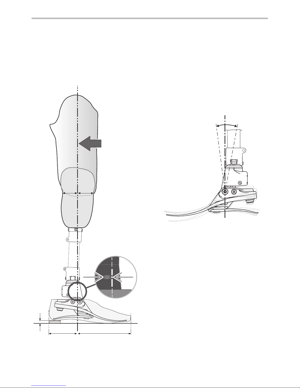
6°3°
½½
Align transfemoral devices according to tting instructions supplied with the knee.
Keep the build line between pivots as shown, using shift and/or tilt devices as necessary.
Build
Line
6 Bench Alignment
6.1 Static alignment
Allow for users
own footwear
* *
Approx. 1/3 2/3
Tilt setting
Align limb to achieve range of motion
shown.

938280S/2-0718
5
6.2 Biomimetic alignment
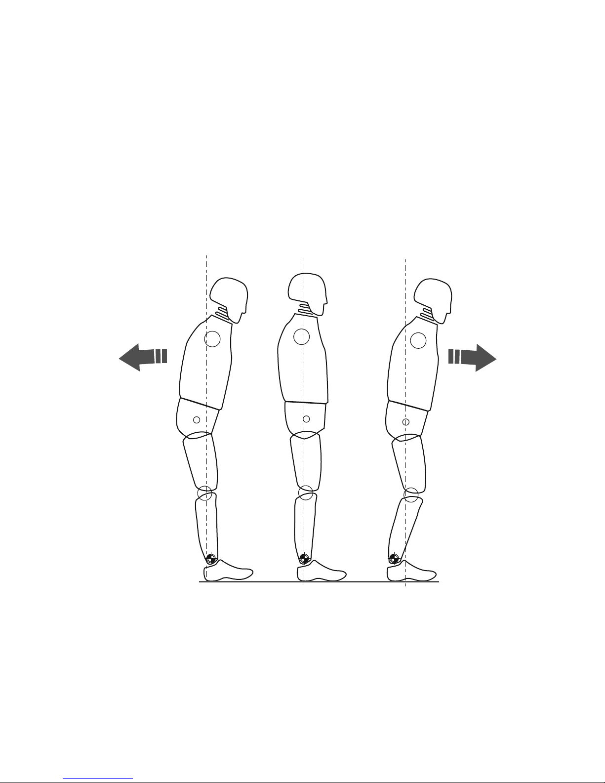
The aim of alignment is to achieve a “balance point” while standing and set the hydraulically
damped range of motion. The aim of damping adjustment is to ne tune the ankle-foot rollover stiness characteristics until a comfortable gait is achieved. Due to the increased range of
motion provided by the ankle the user may experience the need for more voluntary control and
initially nd the ankle disconcerting during setup. This should quickly pass upon completion of
satisfactory setup.
Ensure that the user is relaxed and not resting on the dorsiexion limit.
Falling backwards =
(Hyper-extension)
A–P shift too far forward
Falling forwards =
(Hyper-exion)
A–P shift too far back
938280S/2-0718
6
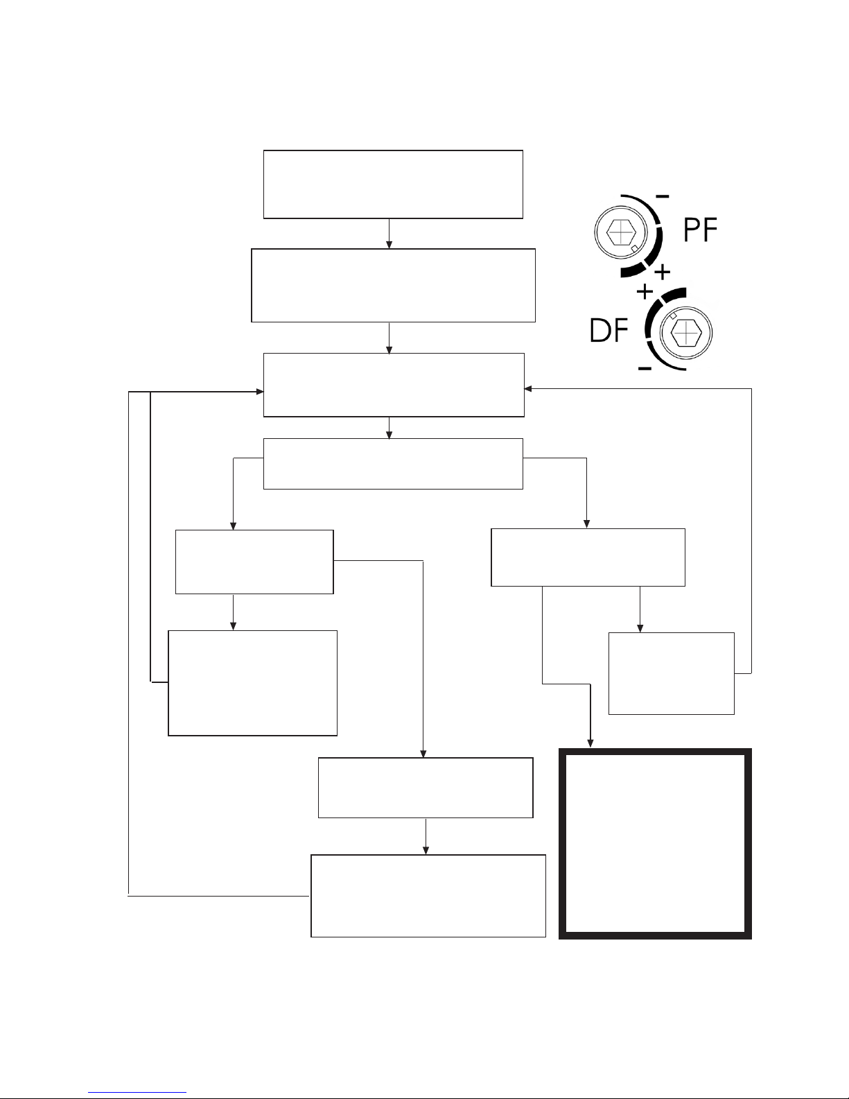
6.3 Biomimetic adjustment
NB: Carry out static alignment while ensuring the user has some means of support such as
parallel bars. This is standing alignment only.
Check bench alignment taking
heel height into account
Ensure PF and DF valves are set as shown.
(the user must feel some movement in
the ankle)
Ask the user to stand with weight
evenly distributed between each foot
Does the user feel sufficiently stable
using minimal muscle control?
No
Yes
Does the user report
a feeling of falling
forwards?
Shift the foot forwards
slightly relative to the
socket (e.g. tilt using
proximal & distal
interfaces)
Yes
No
Yes
Yes
Can the user dorsi-flex the
ankle by approx. 3°?
Adjust the angle
of the foot at the
distal pyramid
interface
Does the user report a
feeling of falling backwards?
Shift the foot backwards slightly
relative to the socket (e.g. tilt
using proximal & distal interfaces)
Proceed to
Dynamic
Adjustment
Allow user to become
accustomed to the ankle for
10 mins before carrying
out any DF/PF valve
adjustments
Use shift for static alignment and standing.
The device should encourage some degree of self adjustment to achieve a sense of
balance for the user during standing.
No
}
938280S/2-0718
7
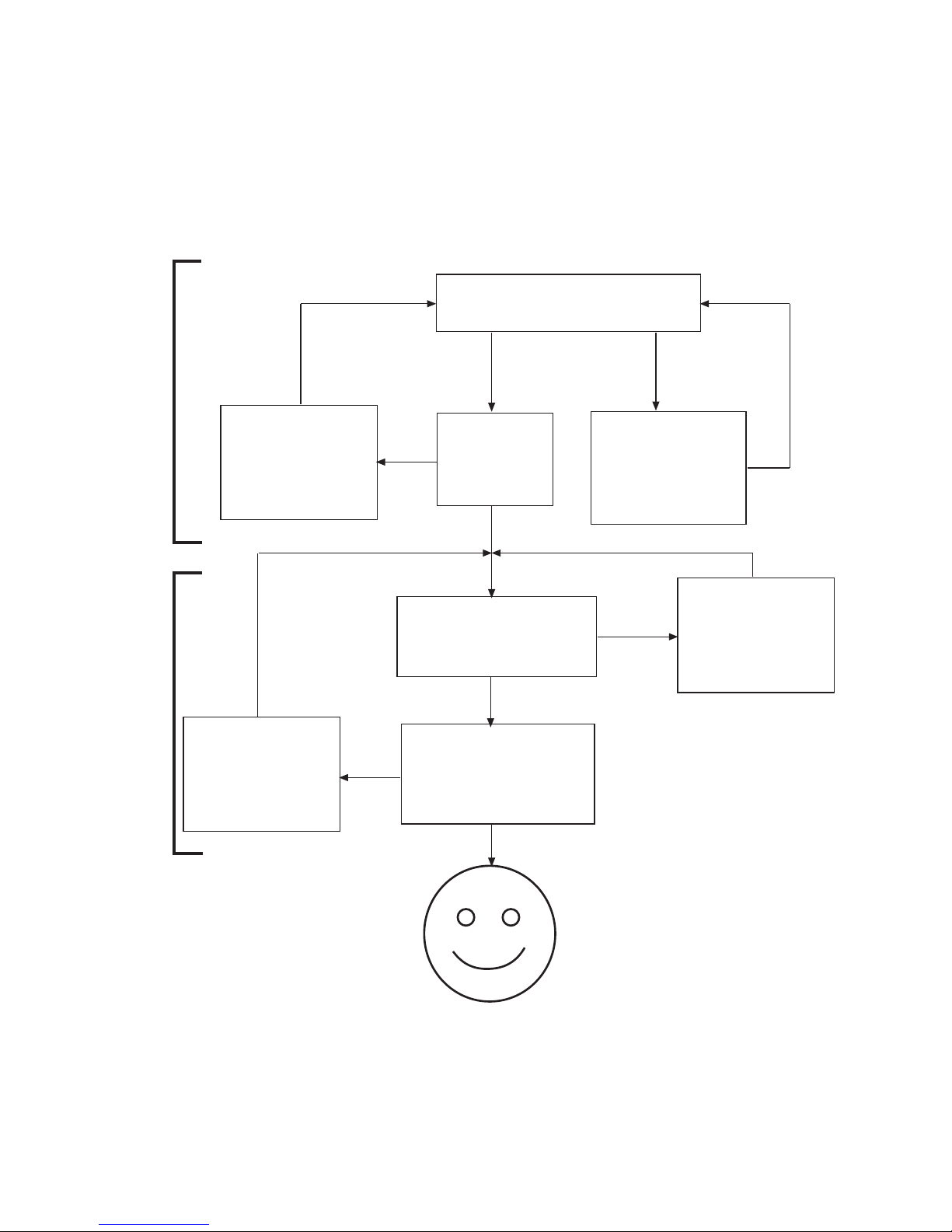
Upon walking, does the user
experience foot slap?
No
Yes
Adjust the Plantar
flexion valve to
reduce resistance
(counterclockwise)
No
Yes
Yes
Yes
No
No
Adjust the Plantar
flexion valve to
increase resistance
(clockwise)
Adjust the
Dorsiflexion
valve to
reduce resistance
(counterclockwise)
Does the
user find the
heel too
hard?
Transfer should be smooth.
Does the user feel as if they
are walking uphill?
Does the user feel as
if they are being
thrown forwards
through stance?
Adjust the
Dorsiflexion
valve to
increase resistance
(clockwise)
PF
1st
6.4 Dynamic adjustment
Adjustment of the hydraulic valves.
The user should experience the ankle moving with the body through the gait cycle. There should
be no eort exerted by the user to overcome the hydraulic resistance of the ankle.
Guidance:
Following dynamic adjustment, trial the foot/ankle on ramps and stairs. Ensure the user is
comfortable with the kind of terrain he/she may normally be expected to encounter. If the user
reports any issues with comfort, usability or range of movement of the ankle, adjust accordingly.
DF
2nd

938280S/2-0718
8
7 Fitting Advice
The correct alignment (A–P position), range of motion (distribution of plantar to dorsiexion) and
adjustment of the hydraulic settings are critical in achieving a smooth roll over and correct slope
adaptation (see 6.3).
The springs for the Echelon foot will be supplied assembled with heel and toe springs of the
same category. If after following the instructions below you still have problems with the function
please contact the sales team in your area for advice.
Any of the following:
• Incorrect spring selection
• Incorrect A–P shift alignment
• Incorrect distribution of plantar and dorsiexion range will have a negative eect on
function and stability
Symptoms Remedy
1.
Sinking at heel strike
Diculty in achieving a smooth
progression to mid stance
User feels they are walking up hill
or forefoot feels excessively long
1. Increase plantar exion resistance
2. Check A–P shift alignment; ensure foot is not too
anteriorly positioned
3. Check distribution of plantar and dorsiexion
movement; ensure that the plantar exion range
is not excessive
4. Check spring category is not too soft,
if so t a higher rate spring
2.
Progression from heel strike to mid
stance is too rapid
Diculty in controlling the energy
return from the foot at the heel
strike (reduced knee stability)
User feels heel is too hard, fore foot
is too short
1. Reduce plantar exion resistance
2. Check A–P shift alignment; ensure foot is not too
posteriorly positioned
3. Check distribution of plantar and dorsiexion
movement; ensure that there is adequate
plantar exion range
4. Check the spring category is not too high for the
weight and activity of the user, if so t lower rate
spring
3.
Heel contact and progression feel
OK but:
Forefoot feels too soft
Forefoot feels too short
User feels they are walking down
hill, possibly with reduced knee
stability
Lack of energy return
1. Increase dorsiexion resistance
2. Check A–P shift alignment;
ensure foot is not too posteriorly positioned
3. Check distribution of plantar and dorsiexion
movement; ensure that there is not excessive
dorsiexion range
4. Check the spring category is not too soft for the
weight and activity of the user, if so t higher
rate spring
938280S/2-0718
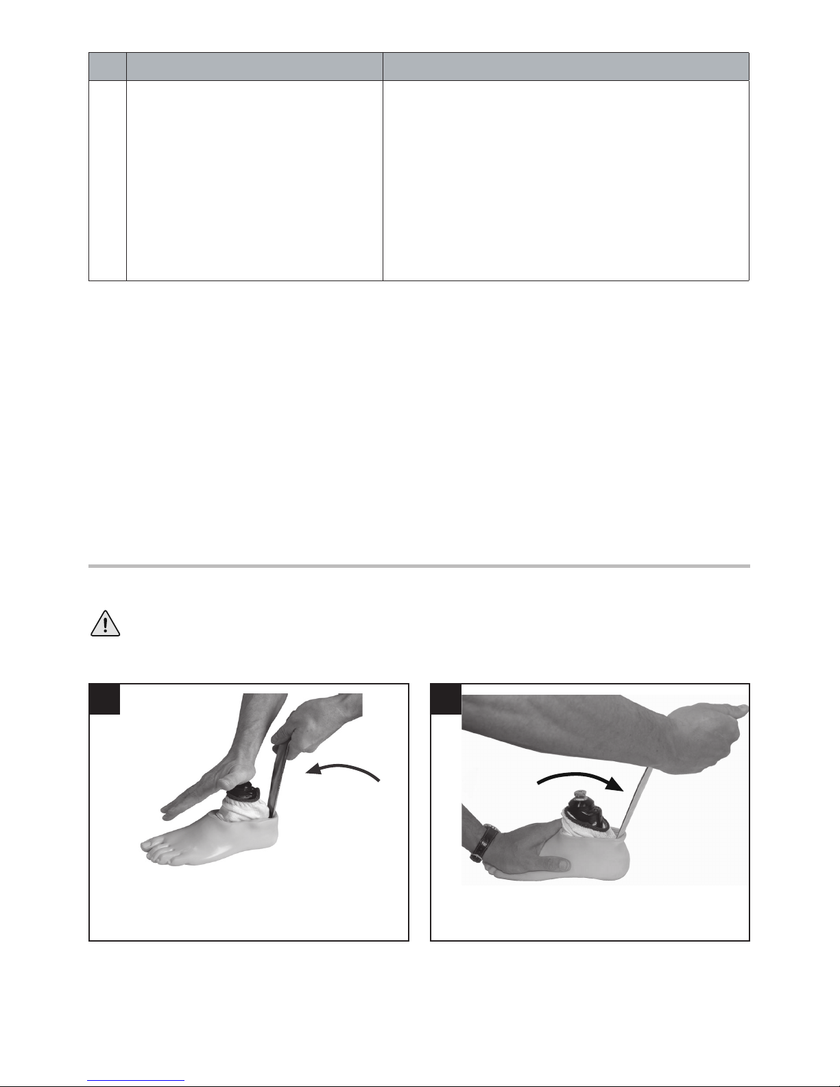
Be aware of nger trap hazard at all times.
1 2
9
Symptoms Remedy
4.
Forefoot feels too rigid
Forefoot feels too long
Feels like walking up hill
1. Reduce dorsiexion resistance
2. Check A–P shift alignment;
ensure foot is not too anteriorly positioned
3. Check distribution of plantar and dorsiexion
movement; ensure that there is sucient
dorsiexion range
4. Check the spring category is not too rigid for the
weight and activity of the user, if so t lower rate
spring
Insert shoe horn behind heel spring.
Rotate shoe horn as shown to remove shell.
8 Assembly Instructions
Foot shell removal

938280S/2-0718
If a foam cosmesis is to be tted, roughen
top surface of foot shell to provide ideal
bonding surface.
3 4
5 6
87
10
Heel Spring
Re-assemble with replacement heel spring. Use
Loctite 243 (926012) and torque to 15 Nm.
Remove heel spring and screws.
4
4
15 Nm
Spring replacement
Cover
appropriate lines
on carrier with
permanent black
marker to leave
spring set
number showing.
Carrier
Assembly
Remove toe spring screw, replace toe. Upon
reassembly, use Loctite 243 (926012) and torque
to 35 Nm. Ensure toe spring is central to the
carrier.
35 Nm
8
Toe Spring
8 Assembly Instructions (continued)
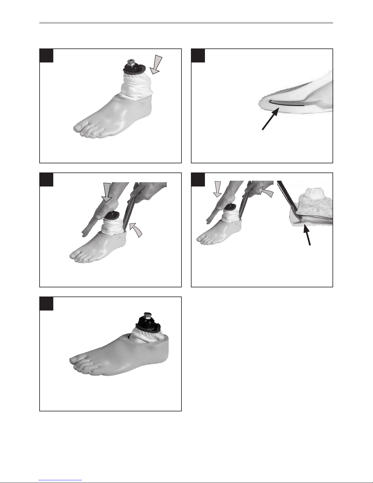
Lubricate toe and heel if required.
(Foot shell is pre-lubricated).
928017
Fit sock as shown.
938280S/2-0718
9 10
11 12
13
11
If a cosmetic nish is required please contact a member of the Endolite Sales Team.
Slide carrier/heel spring assembly into the foot
shell.
Use a suitable lever to encourage the heel spring
into location in the foot shell.
Ensure glide sock does not get trapped when
assembling to female pyramid part.
8 Assembly Instructions (continued)
Ensure heel spring is engaged into slot.
heel spring
location slot
Toe spring location in foot shell.
938280S/2-0718
12
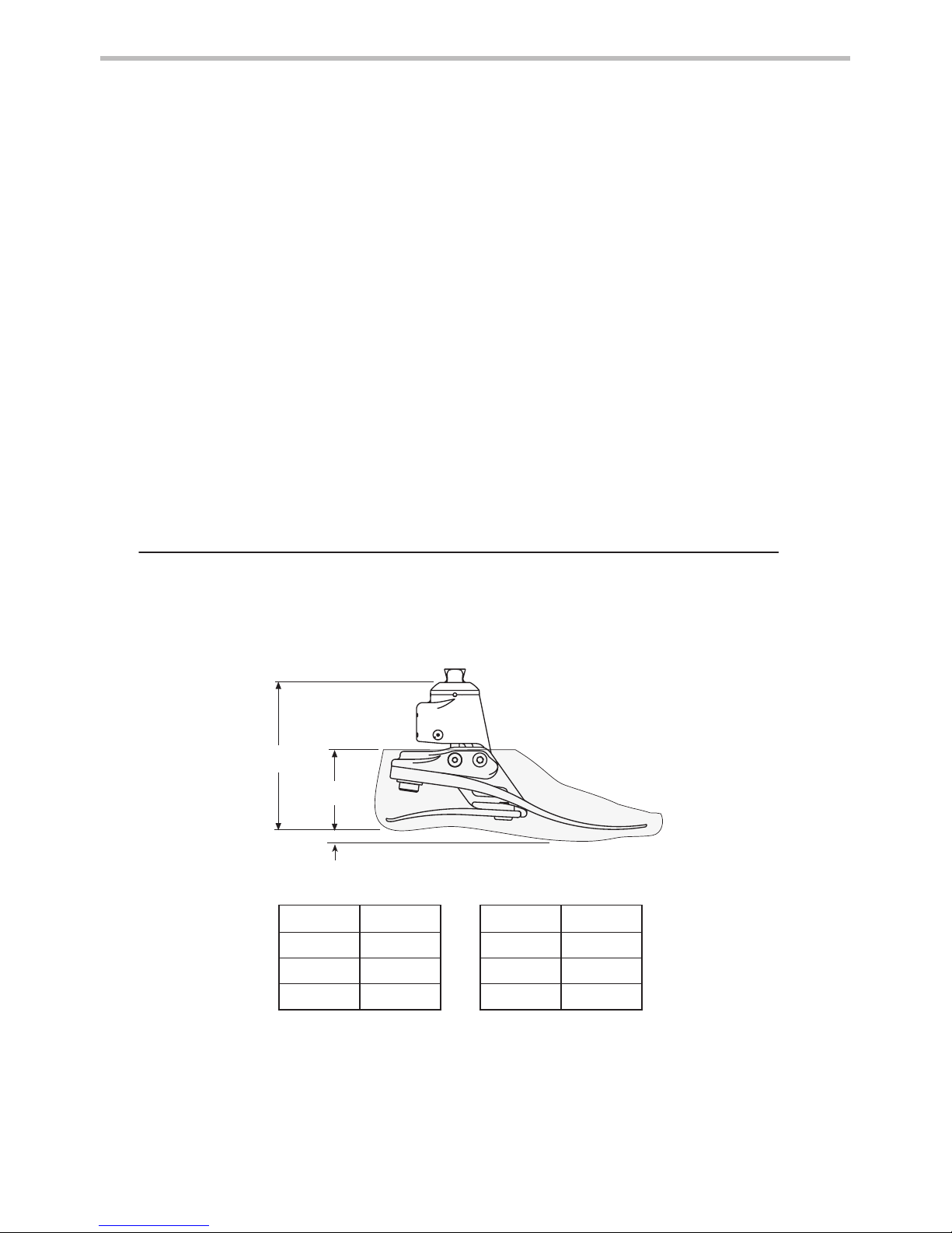
10 mm
A
B
Fitting length
9 Technical Data
Operating and
Storage Temperature Range:
-15 ˚C to 50 ˚C
(5 ˚F to 122 ˚F)
Component Weight (Size 26N) 900 g (2lb)
Activity Level: 3
Maximum User Weight: 125 kg (275 lb)
Proximal Alignment Attachment: Male Pyramid (Endolite)
Range of Hydraulic Ankle Motion
(excludes additional range of motion
provided by heel and toe springs)
6 degrees plantar flexion
to 3 degrees dorsiexion
Build Height:
(See diagram below)
(sizes 22–24) 115 mm
(sizes 25–26) 120 mm
(sizes 27–30) 125 mm
Heel Height 10 mm
Size A Size B
22–24 115 mm 22–26 65 mm
25–26 120 mm 27–28 70 mm
27–30 125 mm 29–30 75 mm

938280S/2-0718
13
10 Ordering Information
Order Example
DF/PF Adjuster Key: 4.0 A/F Allen 940236
Foot Shell (for dark add ‘D’)
Glide Sock
Size/Side Narrow Wide
22L 539038S -
531011
22R 539039S -
23L 539040S -
23R 539041S -
24L 539042S -
24R 539043S -
25L 539044SN 539044SW
25R 539045SN 539045SW
26L 539046SN 539046SW
26R 539047SN 539047SW
27L 539048SN 539048SW
532811
27R 539049SN 539049SW
28L - 539050S
28R - 539051S
29L - 539052S
29R - 539053S
30L - 539054S
30R - 539055S
Spring Kits
Rate
Foot sizes
Small (S) Medium (M) Large (L) Extra Large (XL)
22–24 25–26 27–28 29–30
Set 1 539801S 539810S 539819S 539828S
Set 2 539802S 539811S 539820S 539829S
Set 3 539803S 539812S 539821S 539830S
Set 4 539804S 539813S 539822S 539831S
Set 5 539805S 539814S 539823S 539832S
Set 6 539806S 539815S 539824S 539833S
Set 7 539807S 539816S 539825S 539834S
Set 8 539808S 539817S 539826S 539835S
Available from size 22 to size 30:
EC22L1S to EC30R8S
EC22L1SD to EC30R8SD
(add ‘D’ for a dark tone foot shell)
EC 25 L N 3 S
Size Side
(L/R)
Width*
(N/W)
Spring Set
Category
Sandal
Toe
*Sizes 25-27 only. For all other sizes, omit the Width eld.
e.g. EC25LN3S, EC22R4S, EC27RW4SD

938280S/2-0718
14
Blatchford Products Ltd. and ENDOLITE are companies and trademarks of Chas. A. Blatchford and Sons Ltd.
Liability
The manufacturer recommends using the device only under the specied conditions and for
the intended purposes. The device must be maintained according to the instructions for use
supplied with the device. The manufacturer is not liable for damage caused by the component
combinations that were not authorized by the manufacturer.
CE Conformity
This product meets the requirements of 93/42/EEC guidelines for medical products. This product
has been classied as a Class 1 Product according to the classication criteria outlined in
Appendix IX of the guidelines. The Declaration of Conformity was therefore created by Blatchford
Products Limited with sole responsibility according to Appendix VII of the guidelines.
Warranty
This device is warranted for 36 months - foot shell 12 months - glide sock 3 months. The user
should be aware that changes or modications not expressly approved could void the warranty,
operating licenses and exemptions. See Endolite website for the current full warranty statement.
Environmental Aspects
Where possible the components should be recycled in accordance with local waste handling
regulations.

938280S/2-0718
FR
15
Application
Ces instructions sont destinées à l’attention de l’orthoprothésiste.
L’Echelon doit être utilisé dans le cadre d’une prothèse de membre inférieur.
Ce dispositif fournit un auto-alignement limité de la prothèse sur divers terrains et en cas de changement
de chaussure. Il est conçu pour améliorer l’équilibre et la symétrie de la posture tout en atténuant les
pressions anormales à l’interface moignon/emboîture. Un pied à la restitution d’énergie modérée avec
mouvement de cheville multi-axial. Le talon indépendant et les ressorts d’orteils procurent une certaine
déexion axiale. L’orteil divisé procure une bonne adhérence au sol.
Ce dispositif est conseillé à l’usage pour les patients au niveau d’activité 3 qui peuvent tirer prot d’une
stabilité et d’une conance accrues sur sols irréguliers.
Il existe évidemment des exceptions et nos recommandations tiennent compte de circonstances
uniques et spéciques. Par ailleurs, des utilisateurs au niveau d’activité 2 et 4* pourraient
éventuellement tirer parti de la stabilité accrue oerte par Echelon, bien que cette décision puisse
uniquement être prise après complète justication.
(*poids maximum du patient 100 kg, toujours choisir la catégorie supérieure à celle préconisée dans le
tableau pour compenser le niveau d’activité).
An de minimiser les risques de glissades et/ou de faux pas, il faut toujours utiliser des chaussures
appropriées qui tiennent bien à l’enveloppe esthétique.
Sachez que vous risquez toujours de vous pincer les doigts.
Contre-indications
Ce dispositif peut ne pas convenir aux individus au niveau d’activité 1 ou aux patients participant à
des manifestations sportives de compétition, car ces utilisateurs seront mieux servis par une prothèse
spéciquement conçue et optimisée pour leurs besoins.
Destiné à un usage individuel.
Veiller à ce que l’utilisateur ait bien compris toutes les instructions, notamment tout ce qui concerne la
maintenance.
Note:
En cas de doute entre deux catégories de lames, choisir la plus dure.
Les recommandations de jeux de lames repésentés sont pour un patient amputé tibial.
Pour un amputé fémoral nous conseillons de prendre la catégorie en dessous tout en
veillant à respecter les grilles de poids. Se référer à la section 7 de la notice de montage
pour assurer une fonction et une amplitude satisfaisante.
A la capacité ou le potentiel pour se déplacer à des cadences variables.
Typique des patients aptes à gérer la majorité des obstacles environnementaux
et pouvant avoir une activité professionnelle ou thérapeutique qui exige
l’utilisation d’une prothèse au-delà de la simple locomotion.
Activité 3
1 Description et objectif
Choix du jeu de Lames
Activité
Jeu de
lames
44–52 53–59 60–68 69–77 78–88 89–100 101-116 117-125
kg
100-115 116-130 131-150 151-170 171-195 196-220 221-255 256-275
lbs
1 2 3 4 5 6 7 8
Poids de l’utilisateur
3
938280S/2-0718
Ensemble support et
corps hydraulique
Réglage de
valve de exion
plantaire
Rondelle de lame
d’avant pied
Vis de lame d’avant
(Loctite 243)
Lame de
talon
Vis de lame
de talon 15
Nm (Loctite
243)
Lame
d’avant pied
Réglage de valve
de dorsiexion
(opposé au
réglage de
exion plantaire)
16
Composants principaux :
• Corps hydraulique comprenant la pyramide (aluminium/acier inox/titane)
• Châssis (aluminium/acier inox)
• Lames de talon et d’avant pied (E-Carbon)
• Vis de xation de lames (titane/acier inox)
• Chaussette de protection (UHM PE)
• Enveloppe de pied (PU)
2 Construction
8
4
15 Nm
35 Nm
PF
Min
Max
DF
Min
Max
Chaussette de
protection
Enveloppe
de pied

938280S/2-0718
17
L’entretien doit être eectué par une personne qualiée.
Il est recommandé d’eectuer l’entretien suivant annuellement :
• Retirer l’enveloppe de pied et la chaussette de protection, rechercher des dommages ou une usure et
remplacez au besoin.
• Vérier le serrage de toutes les vis, nettoyer et remonter au besoin.
• Rechercher visuellement des signes de délamination ou d’usure des lames de talon et d’avant pied
et remplacer au besoin. Une légère dégradation de la surface peut se produire après une période
d’utilisation, ceci n’aecte pas la fonction ni la résistance du pied.
Les changements de performance peuvent inclure :
• Augmentation de la rigidité de la cheville
• Réduction du soutien de la cheville (liberté de mouvements)
• Bruit inhabituel
L’orthoprothésiste doit également être informé de tout changement dans le poids corporel et / ou le niveau
d’activité du patient.
L’utilisateur doit être informé qu’une vérication visuelle régulière du pied est recommandée.
les signes d’usure pouvant aecter sa fonction doivent être signalés à son orthoprothésiste
(par exemple, usure importante ou décoloration excessive due à une exposition à long terme aux UV).
Nettoyage :
Utiliser un chion humide et un savon doux pour nettoyer les surfaces extérieures; n’utiliser pas de détergent
agressif.
L’Echelon comporte un corps hydraulique contenant des valves réglables.
Les valves peuvent être ajustées de manière indépendante pour augmenter ou réduire la résistance
hydraulique à la exion plantaire et/ou dorsale.
Cet ensemble est connecté à un support à l’aide de deux pivots. Les lames de talon et d’avant-pied sont
xées au support par des vis en inox et titane. Le pied est enveloppé dans une chaussette en PE UHM qui est
insérée dans une enveloppe de pied en PU.
Durée de vie prévue
Une évaluation des risques locaux doit être eectuée en fonction de l’activité et de l’utilisation.
Port de charges
Le poids et l’activité de l’amputé sont régis par les limites indiquées.
Le port de charges par l’amputé doit être basé sur une évaluation des risques locaux.
Environnement
Le produit est étanche sur une profondeur maximale de 1 mètre.
Rincez abondamment à l’eau claire après utilisation dans un environnement abrasif comme ceux susceptibles
de contenir du sable ou des gravillons, par exemple, pour prévenir l’usure ou d’endommager les pièces
mobiles;
Rincez abondamment à l’eau claire après utilisation dans de l’eau salée ou dotée de chlore.
Les éléments de pied doivent bénécier d’une nition adéquate pour empêcher l’eau de pénétrer dans
l’enveloppe de pied autant que possible. Si de l’eau pénètre dans l’enveloppe, le dispositif doit être retourné
et séché avant une nouvelle utilisation.
Exclusivement pour une utilisation de -15°C à 50°C.
On recommande de n’utiliser que les produits Endolite avec
l’Echelon.
3 Fonction
4 Entretien
5 Limites d’utilisation :
938280S/2-0718
18
6°3°
½½
6.1 Alignement à l’établi
Aligner les dispositifs trans-fémoraux selon les instructions fournies avec le genou. Maintenir
l’axe de construction entre les pivots comme représenté, en utilisant des dispositifs de translation
et/ou inclinaison selon le cas.
Réglage d’inclinaison
Aligner l’appareil pour obtenir
l’amplitude de mouvement représentée.
Axe de
constuction
10 mm pour tenir
compte de la hauteur
du talon
6 Alignement
*
*
Environ. 1/3 2/3
938280S/2-0718
19
6.2 Alignement biomimétique
L’alignement a pour objectif l’obtention d’un « point d’équilibre » en position debout
et le réglage de l’amplitude de mouvement amortie hydrauliquement. L’objectif
du réglage de l’amortissement est de régler avec précision les caractéristiques de
rigidité de déroulement cheville-pied jusqu’à l’obtention d’une démarche confortable.
En raison de l’amplitude de mouvement accrue fournie par la cheville, l’utilisateur
peut ressentir le besoin d’un contrôle plus volontaire et trouver au début la cheville
déconcertante pendant la mise en place.
Ceci doit rapidement disparaître une fois la conguration satisfaisante obtenue.
s’assurer que l’utilisateur est détendu et ne repose
pas sur la limite (butée) de exion dorsale
Chute vers l’arrière
(hyperextension)
pied décalé trop
vers l’avant
Chute vers l’avant
(hyperexion)
pied décalé trop
vers l’arrière
938280S/2-0718
20
S’assurer que les valves PF et DF sont comme représentées.
(l’utilisateur doit sentir un certain mouvement dans la
cheville)
Demander au patient de se tenir debout avec le
poids également réparti sur chaque pied
Se sent-il suffisamment stable avec un
minimum de contrôle musculaire ?
Non
Oui
L’utilisateur signale-t-il une
sensation de chute en
avant ?
Déplacer le pied légèrement
vers l’avant par rapport à
l’emboîture (par exemple
incliner avec les adaptateurs
proximal et distal)
Non
Oui
Oui
Oui Non
L’utilisateur peut-il dorsi-fléchir la
cheville d’environ 3° ?
Ajuster l’angle du pied
à l’adaptateur de la
pyramide distale
L’utilisateur signale-t-il une sensation
de chute en arrière ?
Déplacer le pied légèrement vers l’arrière
par rapport à l’emboîture
(par exemple incliner avec les interfaces
proximales et distales)
Passer à
l’alignement
dynamique
Permettre à l’utilisateur de
s’habituer à la cheville pendant
10 minutes au moins avant de
faire des réglages de Flexion
Plantaire / Flexion Dorsale
Utiliser la translation pour l’alignement statique en position debout.
Le dispositif doit encourager un certain niveau d’auto alignement an d’obtenir une
sensation d’équilibre pour le patient qui se tient debout.
Contrôler l’alignement à l’atelier en tenant
compte de la hauteur du talon
6.3 Alignement biomimétique
NB: eectuer un alignement statique tout en s’assurant que l’utilisateur a un soutien tel
que des barres parallèles. C’est un alignement debout seulement.
}
938280S/2-0718
21
Guide
Après le réglage dynamique, essayer le pied/la cheville sur des plans inclinés et des
escaliers. S’assurer que l’utilisateur est confortable sur les types de terrain qu’il peut
normalement rencontrer.
S'il signale des problèmes de confort, commodité ou amplitude de mouvement de la
cheville, ajuster en conséquence.
Lors de la marche, l’utilisateur ressent-
il un claquement du pied ?
Non
Oui
Ajuster la valve de
flexion plantaire pour
diminuer sa résistance
(sens anti horaire)
Non
Oui
Oui
Oui
Non
Non
Ajuster la valve de
flexion plantaire
pour augmenter sa
résistance
(sens horaire)
Ajuster la valve de
flexion dorsale pour
diminuer sa résistance
(sens anti horaire)
L’utilisateur
trouve-t-il le
talon trop dur ?
Le transfert doit être progressif.
L’utilisateur a-t-il l’impression de
monter un plan incliné ?
PF
1st
DF
2nd
L’utilisateur a l’impression
d’être projeté vers l’avant
pendant le pas ?
Réglez la valve de
flexion dorsale
pour augmenter la
résistance
(sens horaire)
6.4 Réglage dynamique
Ajustement des valves hydrauliques. L’utilisateur doit ressentir le mouvement de la
cheville avec le corps pendant le cycle de marche. Il ne doit faire aucun eort pour
surmonter la résistance hydraulique de la cheville.
 Loading...