


Instructions for Use

938321WEB-GB/1-1012
1 Description and purpose
2
The AqualimbTF is a prosthetic knee designed for above knee users.
The knee is water resistant and is intended for use as a shower limb ONLY.
Application:
These instructions are for use by the Clinician/Practitioner
The product is to be used exclusively as part of a lower limb prosthesis
Intended for single user
Maximum user weight 100kg
Ensure that the user has understood all instructions for use, drawing particular
attention to the section regarding safety and maintenance.
Features:
• Geometrically stable 4 bar knee
• Hand operated knee lock, HOKL
• Corrosion resistant
Activity level:
Although intended for Activity Level 2 this device will benet Activity Level 3 and 4 users for
the purpose of showering only.
Contra-indications:
This device may not be used for any activity above level 2.
As the AqualimbTF is a free swinging device when the lock is not engaged , only users who
can oer some control of the swing should be prescribed with the knee.
Not for use by transtibial users.
Checking the package contents:
1. Shin/Foot
2. Top Housing
3. Knee
4. Distal attachment nut, bolt and washer
5. Instructions for Use
6. User Guide
938321WEB-GB/1-1012
3
Available from size 22 to size 27:
AQTF22L to AQTF27R
Size/Side
Order Example:
e.g. AQTF25L
AQTF
25L
Safety Information
1. Any changes in performance for example ‘play’, instability, lock not engaging,
or changes in swing resistance should immediately be reported to your service
provider.
2. Take all necessary safety precautions and due care on wet and slippery surfaces.
3. Avoid exposure to extreme heat and/or cold.
4. The product is not suitable for activities such as sports, running or cycling, ice and
snow sports, slopes and steps. Any such activities are undertaken completely at the
users’ own risk.
5. The user must not adjust or tamper with the set-up of the product.
6. The user should be advised to contact their clinician if their condition changes.
7. The freedom of swing of the knee will vary slightly between when the knee is dry
and when it is wet and /or contaminated with soap for example.
Be aware of a potential nger trap hazard at all times

938321WEB-GB/1-1012
4
2 Construction
Principal parts:
• Knee mechanism
• (Acetal Homopolymer, Stainless Steel)
• Top housing
• (Glass bre reinforced Nylon)
• Foot keel /shin
• (Glass bre reinforced Nylon/PU)
• Attachment parts
• (Stainless Steel/ Aluminium Alloy)
Knee mechanism
Top housing
Foot keel/shin
Attachment parts
Lock
Actuator
938321WEB-GB/1-1012
5
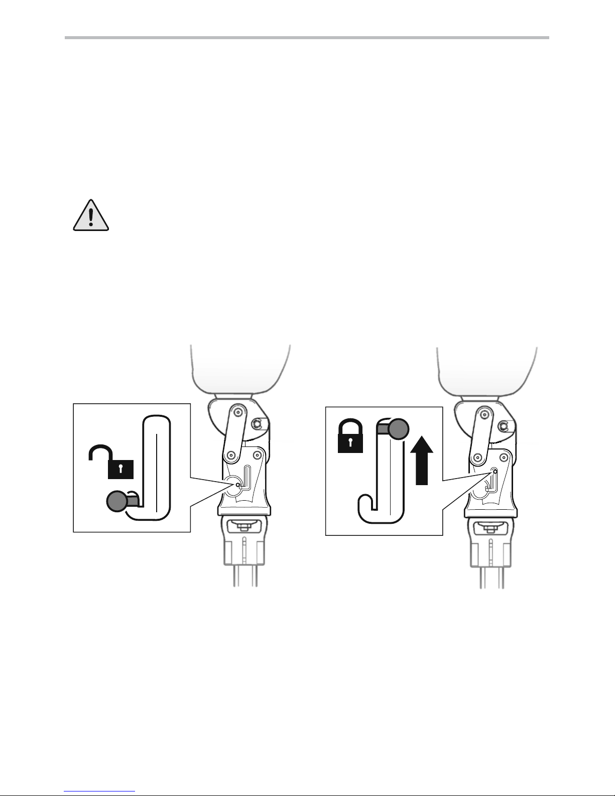
3 Function
Knee shown with lock in place.Knee shown in free mode.
The lock will not engage at full knee
extension.
Knee locked:
Actuator fully engaged in top position
Knee lock operation
The knee has a polycentric design comprising pivots connecting a chassis to a main
body via three link arms. A hand operated spring loaded pin operates within a latched
slot in the body. The pin may be located to engage into the chassis and lock the knee
in full extension. A housing is bolted to the distal aspect of the knee into which is
clamped a foot/shin component. The shin may be shortened to suit the user . The sole
of the foot features an anti-slip tread pattern.
If lock mode is required ensure that the lock actuator is fully engaged
before walking or showering.
Knee unlocked:
Actuator in down position
The lock is hand operated. To lock the knee release the acuator from the down position,
fully extend the knee and push the actuator up to the top position and ensure the
actuator is fully engaged as shown.

938321WEB-GB/1-1012
6
4 Maintenance
Maintenance must be carried out by competent personnel.
It is recommended that the following maintenance is carried out annually:
• Check the security of the proximal attachment nut and distal alignment bolt.
• Check for satisfactory function of knee lock and freedom of swing.
• Visually check for wear. Some surface damage may occur after a period of use; this
does not aect the function or strength of the device.
The wearer should be advised:
Any changes in performance of this device must be reported to the practitioner.
Changes in performance may include:
• ‘Play’ in moving parts
• Lock not engaging
• Instability
Check condition of knee bumper and replace if necessary.
Cleaning:
Use a damp cloth and mild soap to clean outside surfaces, DO NOT use aggressive
cleansers, wipe dry.
5 Limitations on use:
Intended life:
Service life of the product is covered by the warranty period - a local risk assessment
should be carried out based upon activity and usage.
Lifting loads:
User weight and activity is governed by the stated limits.
Load carrying by the user should be based on a local risk assessment.
Environment:
Avoid excessive contact with abrasive environments such as those containing sand for
example, and rinse thoroughly after any such exposure.
Exclusively for use between -15˚C and 50˚C.
It is recommended that only Endolite products be used in conjunction with the
product.
938321WEB-GB/1-1012
1
2
3
7
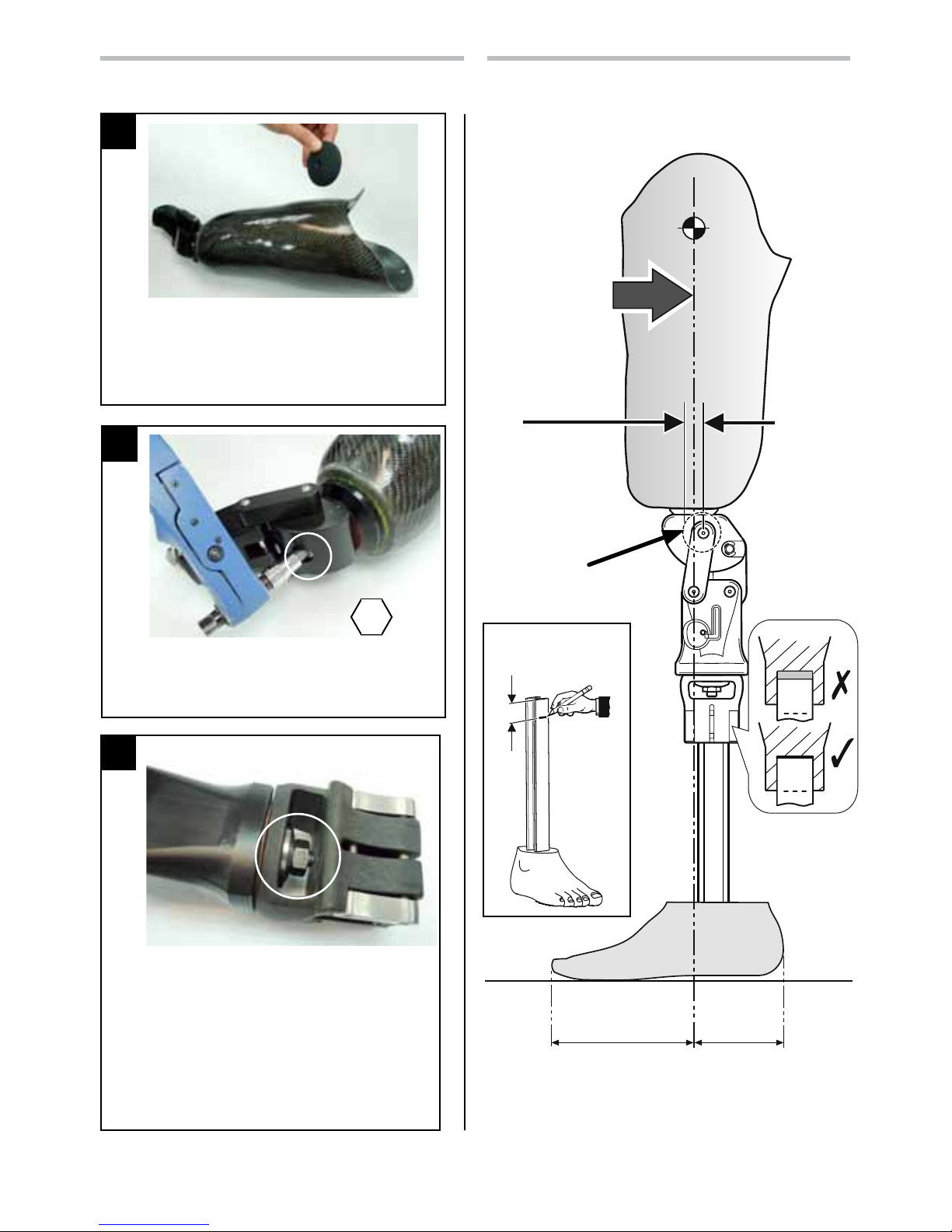
7 Alignment
Top
Pivot Pin
0-12mm
anterior of
Top Pivot Pin
Build
Line
approx.
2
/
3
1
/
3
Build Line
Passes through the
Proximal
Attachment Bolt
6 Assembly Instructions
Manufacture the socket using the appropriate
Endolite single bolt former. Cut a 27mm
diameter hole in distal end of socket. Place
socket plate inside socket. Assemble alignment
parts supplied. Minimum socket thickness 6mm
Apply Loctite 243 and torque the proximal
alignment bolt to 35Nm.
Apply Loctite 243 to bolt threads. Assemble the
distal top housing using the nut and washer
as shown and torque tighten to 35Nm after
alignment.
It may be easier to t the shin before
assembling the top housing.
Ensure full engagement of shin, see diagram
Section 7.
8
35Nm
45mm
Full engagement

938321WEB-GB/1-1012
32
1
8
9 Dynamic Alignment
Set-up as shown in Bench Alignment if the user requires adjustment length, shift,
rotation and angular adjustments are available by loosening, adjusting and retightening of distal and proximal alignment xings.
Ensure after any adjustments are made, that the load line is not posterior to the top
pivot pin.
8 Fitting Instructions
Fit shin to housing ensuring full
engagement. Measure length
to determine amount to be cut
from shin.
Determine nal cut length
required. Remove shin from
housing, cut to length and
reassemble then check
measurement.
Check length and alignment.
Finalise the screw settings
during dynamic alignment.
Tighten clamp screws evenly, applying a torque
of 5Nm at least twice to each screw. Example
order of tightening shown to evenly spread load.
1
2
4
3
45mm

938321WEB-GB/1-1012
9
10 Technical Data
Operating and
Storage Temperature Range:
-15˚C to 50˚C
5˚F to 122˚F
Total Component Weight [size 24]: 2.0kg ( 4.4lbs)
Recommended Activity Level: 2
Maximum User Weight: 100kg
Proximal Alignment attachment: Endolite single bolt alignment
Build Height:
[See diagram below]
400 - 585mm
Fitting Length
135mm
30mm
207mm
15mm
450mm max.
265mm min.
22mm
585mm max.
400mm min.

938321WEB-GB/1-1012
10
This product meets the requirements of 93/42/EEC guidelines for medical products.
This product has been classied as a Class 1 Product according to the classication
criteria outlined in Appendix IX of the guidelines. The Declaration of Conformity was
therefore created by Blatchford Products Limited with sole responsibility according to
Appendix VII of the guidelines.
The manufacturer recommends using the device only under the specied conditions
and for the intended purposes. The device must be maintained according to the
instructions for use supplied with the device. The manufacturer is not liable for damage
caused by the component combinations that were not authorized by the manufacturer.
The aqualimbTF is warranted for 24 months from original date of purchase unless
otherwise stated.
See Endolite catalogue for details.
Liability
CE Conformity
Warranty
Blatchford Products Ltd. and ENDOLITE are companies and trademarks of Chas. A. Blatchford and Sons Ltd.
11 Replacement Parts
Part Part No.
Knee Bumper 622310
Screw Proximal M10 55 ST STL 910420

938321WEB-GB/1-1012
Head Office
Chas A Blatchford & Sons Ltd
Lister Road
Basingstoke
Hampshire
RG22 4AH
United Kingdom
Tel: +44 (0) 1256 316600
Fax: +44 (0) 1256 316617
Email: sales@blatchford.co.uk
www.endolite.co.uk
Customer Services UK
Prosthetic and Orthotic Products
11 Atlas Way
Atlas North
Shefeld
S4 7QQ
United Kingdom
Tel: +44 (0) 114 263 7900
Fax: +44 (0) 114 263 7901
Email: sales@blatchford.co.uk
www.endolite.co.uk
endolite North America
1031 Byers Road
Miamisburg
Ohio 45342
USA
Tel: 800.548.3534
Fax: 800.929.3636
Email: info@endolite.com
www.endolite.com
Distributor/Distributeur/Händler/Distributore/Distribuidor/ Поставщик
endolite Germany
Endolite Deutschland GmbH
Holzstr. 5
95336 Mainleus
GERMANY
Tel: +49 9229 9737 001
Fax: +49 9229 9737 006
Email: info@endolite.de
www.endolite.de
endolite France
Parc d’Activités de l’Aéroport, 125 Impasse
Jean-Baptiste Say
34470 PEROLS
FRANCE
Tel: 00 33 (0) 467 820 820
Fax: 00 33 (0) 467 073 630
Email: contact@endolite.fr
www.endolite.fr
endolite India Ltd
A4 Naraina Industrial Area
Phase - 1
New Delhi
INDIA – 110028
Tel: 91 11 45689955
Fax: 91 11 25891543
Email: endolite@vsnl.com
www.endoliteindia.com
endolite Russia
ООО «Эндолайт Центр»
141011, Московская обл.
г. Мытищи, ул. Октябрьская, д. 10
РОССИЯ
Тел.: +7 495 787 5280
Факс: +7 495 787 5280
Email: sales@endolite.ru
www.endolite.ru
 Loading...