

endolite 4 Bolt ESK+ 239150 User Manual
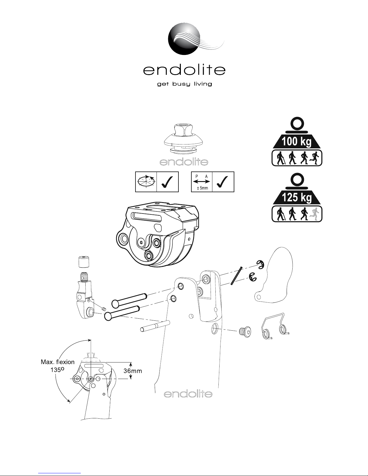
4 Bolt ESK+ 239150
2
Fully extend limb to access the adjuster.
Rotate the SPRING STACK ADJUSTER to
achieve the required stability for the
individual user. Note: Audible clicks
should be heard upon adjustment, and the
adjuster is self locking.
Tighten the SPRING STACK to reduce
stability. Release the SPRING STACK to
increase stability - See above diagram.
If required, the adjuster may be reset to
the factory setting. This can be achieved
by reducing stability by six audible clicks
from the maximum setting.
underside view of chassis
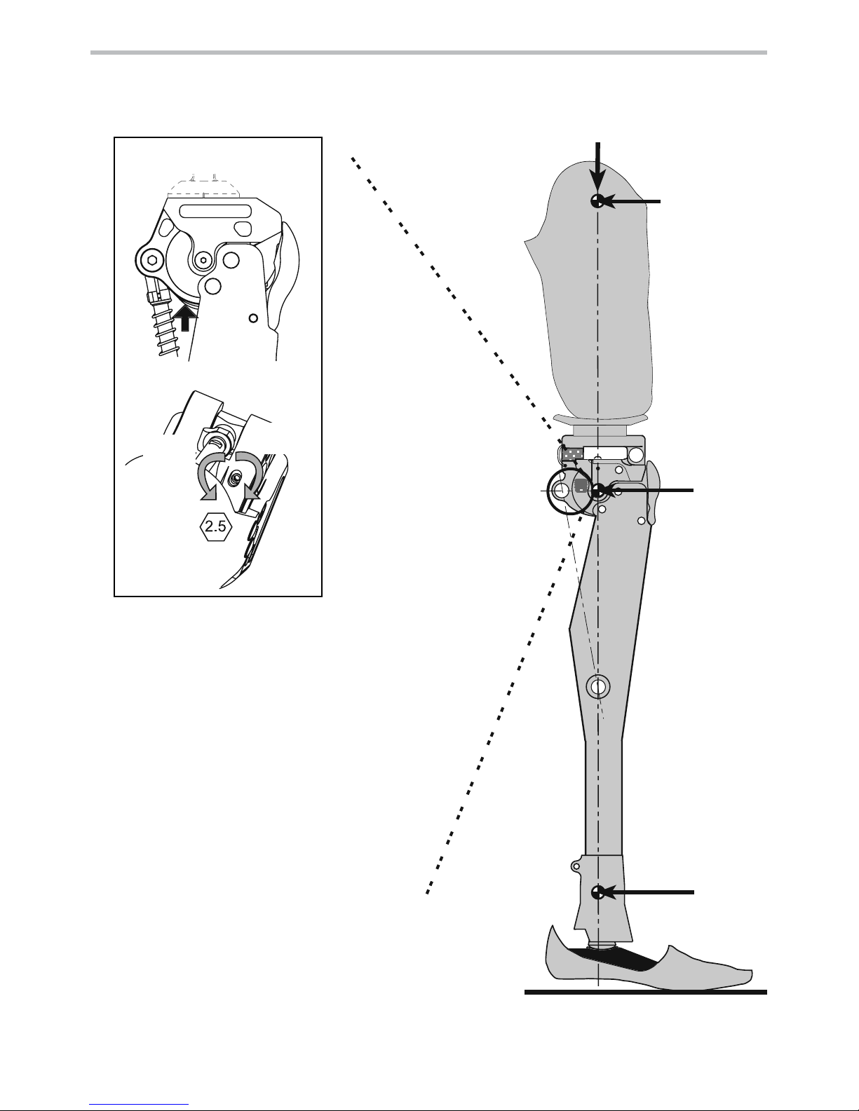
Walking trials
Ankle
Centre
Knee
Pivot
Trochanter
Weight Line
increase
stability
decrease
stability
SPRING STACK ADJUSTER
938205WEB-GB/4-0712
1 Static Alignment Guide
1
3 4
2
3
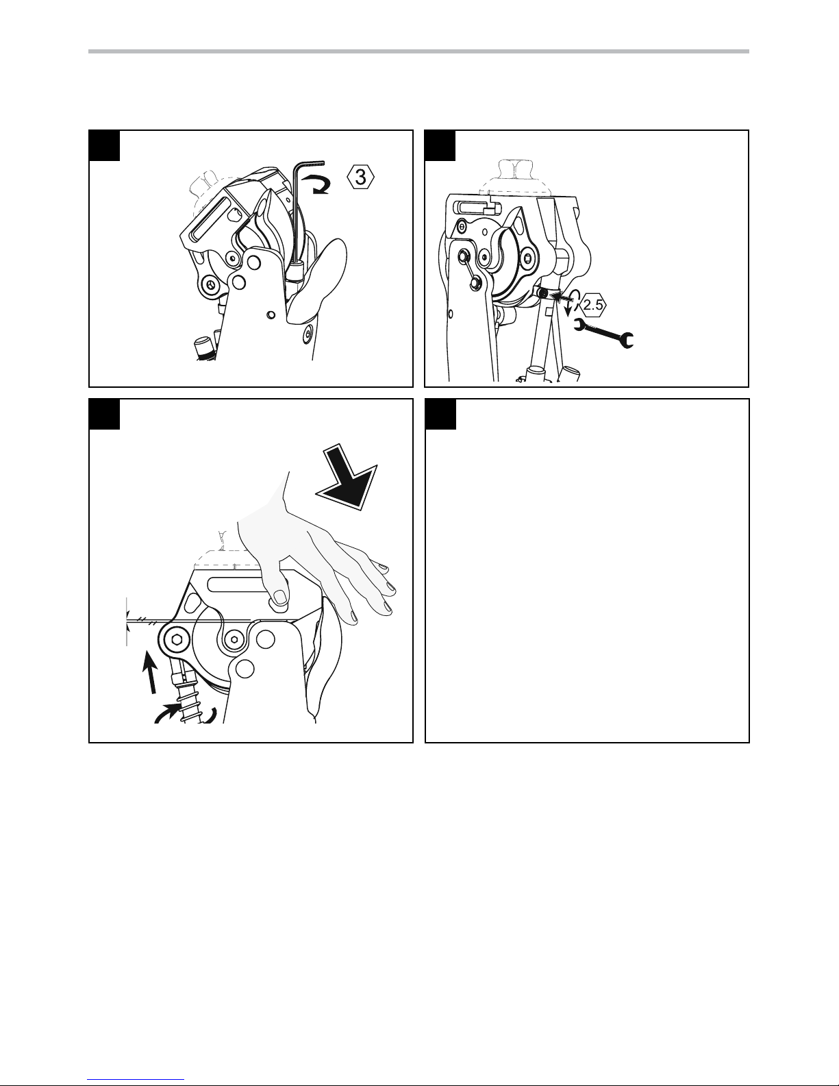
2 Front Stop adjustment - Adjustable Trunnion
As tted to the PSPC and Servo PSPC
Note:The stop pads mounted in the chassis
and side plate are required to support
ML loading. Simultaneous full contact
between the stops and the shin is NOT
required.
Withdraw trunnion clamp screw and
apply LOCTITE 222 to thread, re-assemble
and tighten.
*UNDER NO CIRCUMSTANCES MUST THE
PISTON ROD WITNESS LINE BE VISIBLE
BELOW THE TRUNNION
Servo PSPC
The Servo PSPC should be adjusted as above except
the trunnion should be rotated further, if required,
until the cut-out in the piston rod is posterior.
Fully tighten
front stop
Loosen trunnion
clamp screw. Turn
piston rod to
reveal thread and
apply
Loctite 243.
Reassemble and
screw piston rod
fully home. The
chassis should
now be slightly
exed.
6 A/F - PSPC
9A/F - Servo PSPC
Apply a light extension load
to the knee and gradually
unscrew the piston rod
(lengthening the cylinder)
until the chassis edge is
parallel with the top of the
shin.
Front Stop adjustment - Non-Adjustable Trunnion
[As tted to the IP+ and Hydraulic Cylinders]
No adjustment is necessary when using these cylinders. They require the front stop to be fully tightened as
shown in Stage 1.
938205WEB-GB/4-0712
 Loading...