

Endless Pools FASTLANE Owner's Manual

FASTLANE
By Endless Pools, Inc.
OWNER’S MANUAL
®
F a s t l a n e®S w i m U n i t I n s t a l l a t i o n
Section 1 GENERAL OVERVIEW OF AN ENDLESS POOL FASTLANE
The Fastlane®swimming machine by Endless Pools, Inc. is a hydraulically-powered system that creates a
smooth, adjustable-speed swim current in a conventional pool. The Fastlane has been fabricated with the
finest, most durable materials and designed to meet the most stringent safety standards including VGB
2008. The swim current produced is wider than your body and deeper than your stroke — far superior to
currents created by one or more jets. Two 3/8" hydraulic hoses carrying a non-food grade, biodegradable
vegetable oil run between the hydraulic Power Unit and the Fastlane Swim Unit, thus eliminating the need
for electricity poolside. When pumped at high pressure, this hydraulic fluid creates a swim current by turning the shaft of a submerged stainless steel hydraulic motor in the Fastlane Swim Unit, which in turn rotates
a 16" diameter propeller. The Power Unit is activated using a 3-button radio frequency remote control that
can turn the unit on and off and adjust the speed. It is best if the Power Unit is within 25' of the Swim Unit
to minimize pressure loss. An optional 6" LED swim pace display is available to monitor your speed. Also,
customers often place our swim mirror on the bottom of the pool to observe their swim stroke.
Note: all of the 316L stainless steel screws provided for the assembly of this unit should be tightened to
the recommended 25 in-lbs of torque.
W
= Wall Mount Fastlane = Deck Mount Fastlane
D
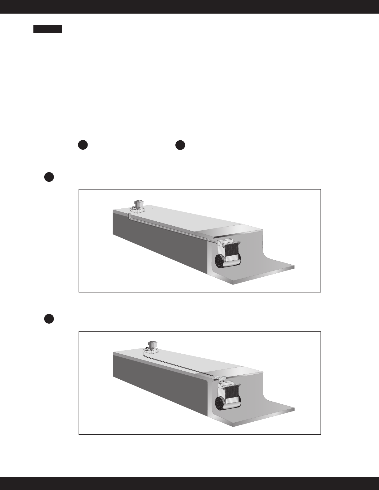
The Fastlane can be mounted one of two ways:
The Wall Mount Fastlane fastens to the wall of the pool using the bracket provided. Two 1" polyethylene
W
pipes (or 1 1/2" PVC pipe) which serve as conduits for the hydraulic hoses run under the pool deck to a remotely located, 5-horsepower, hydraulic Power Unit, as shown in Figure 1.1.
Fig 1.1
The Deck Mount Fastlane fastens to the pool deck using the hanger bracket provided. The two hydraulic
D
lines then run back to the remotely located, 5-horspower, hydraulic Power Unit. The hydraulic hoses can
be run through a conduit or run aboveground, as shown in Figure 1.2.
Fig 1.2
1
F a s t l a n e®S w i m U n i t I n s t a l l a t i o n
Section 2 CHOOSING A LOCATION FOR YOUR FASTLANE
The Fastlane can fit in virtually any swimming pool. For optimal water flow, we recommend that you allow
D
W
at least 12 feet between the wall on which the Fastlane is installed and the opposing wall in line with the
Swim Unit. The Fastlane has more than 9 square feet of water intake to eliminate any entrapment hazards.
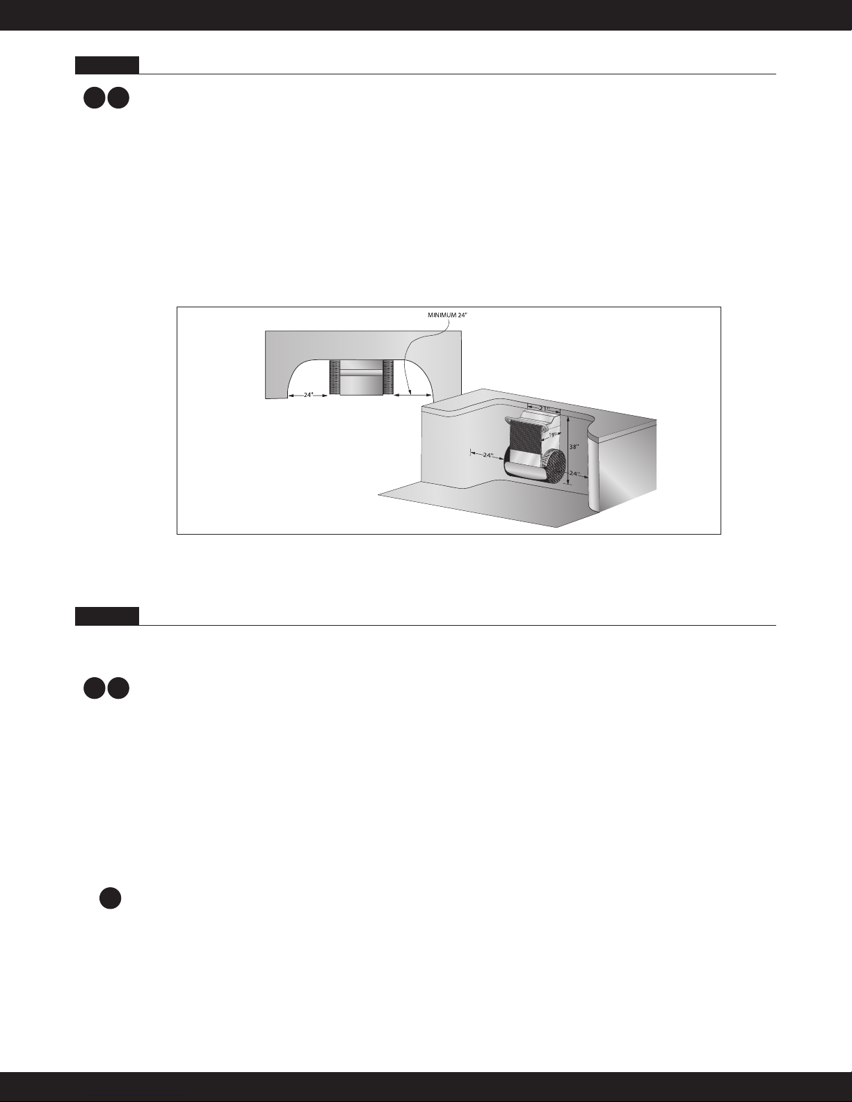
The water depth where the Fastlane is installed must be at least 35" deep. In addition, the Fastlane must be
installed no closer than 24" from any adjacent wall as shown in Figure 2.1, Minimum Clearance Guidelines.
When choosing a location for your Fastlane, you should also consider the route for the hydrualic hoses to
run back to the Power Unit. The Power Unit needs to sit on a solid, level surface, preferably not on wet
ground, and requires a 30-amp, 220-volt GFCI electric service. For UK and international electrical requirements, please refer to Section 11. The optional Outdoor Power Unit with Weather Guard may be located
outside, but should not be subject to driving rain. Typically, the Power Unit is located with the other pool
equipment and, if possible, long hydraulic runs should be avoided because of pressure loss. If you wish to
have a run greater than 25', you must transition from 3/8" hydraulic hoses to 1/2" run hoses with the addition of a junction box as reviewed in Section 5.
Fig 2.1
Section 3 RECEIVING YOUR FASTLANE
Minimum Clearance Guidelines
The Endless Pools Fastlane is comprised of a minimum of five (5) parcels. Additional parcels may be
shipped as appropriate. All items will be shipped via UPS Ground.
Items shipped UPS
D
W
Parcel 1: Fastlane Swim Unit – propulsion housing
Parcel 2: Fastlane Swim Unit – base with pre-installed,
25 feet of hydraulic hoses, grab bar
Parcel 3: 5-hp Power Unit with 2 Wireless Remote Controls and Antenna located inside the controller
(Heavy Box) Note: If the Outdoor Power Unit was purchased as an option, the Weather Guard
will come pre-assembled to the Power Unit.
Parcel 4: Five (5) Gallons of Hydraulic Fluid (Non-Food Grade Vegetable Oil)
Parcel 5: Accessories Kit (Wall Mount or Deck Mount)
Wall Mount Accessories Kit
- Owner’s Manual Kit including:
W
- (2) –8 JIC Female x –6 JIC Male Hydraulic Adapters
- (8) 3/4" stainless steel screws for Fastlane assembly
- (10) 1/2" stainless steel screws for Fastlane assembly
- (6) 3/4" stainless steel screws for Grab Bar installation
- (6) stainless steel nuts for Grab Bar installation
- (2) Protective Hat Channels
- (16) 3/4" stainless steel screws to attach Hat Channels to Upper Housing
- (1) Fastlane Acrylic Top
2

F a s t l a n e®S w i m U n i t I n s t a l l a t i o n
D
Deck Mount Accessories Kit
- Owner’s Manual Kit including:
- (2) –8 JIC Female x –6 JIC Male Hydraulic Adapters
- (8) 3/4" stainless steel screws for Fastlane assembly
- (10) 1/2" stainless steel screws for Fastlane assembly
- (6) 3/4" stainless steel screws for Grab Bar installation
- (6) stainless steel nuts for Grab Bar installation
- (20) 1/2" stainless steel screws for Hanger bracket installation & deck plate assembly
- (1) 3/16" x 2-1/4” Masonry Screws
- (1) 5/32" Masonry Bit
- (4) Hose Clips
- (2) Protective Hat Channels
- (16) 3/4" stainless steel screws to attach Hat Channels to Upper Housing
- (1) Deck Plate Bottom with 3/16" bonding lug attached
- (1) Deck Plate Top
- (1) Fastlane Acrylic Top
The Following two packages will be included ONLY if a Wall Mount Fastlane was purchased:
W
Parcel 6: Wall Mount Bracket Assembly
Parcel 7: Two (2) 24' 6" rolls of 1" Polyethylene Pipe
Optional Equipment
W
D
• Outdoor Power Unit with Weather Guard
• Floor Mirror
• Swim Pace Display
Section 4 WALL MOUNT BRACKET AND 1" POLYETHYLENE PIPE INSTALLATION
NOTE: Please read instructions fully before beginning bracket installation.
4.A. Gunite/Concrete Pool
W
If the pool being constructed is gunite or concrete, please follow the instructions below.
Parcel 6 includes the Wall Mount Fastlane bracket for concrete or gunite pools. Two (2) 24' 6" rolls of 1"
poly pipe are shipped separately. The standard bracket is comprised of the following components
(refer to Photo 4.A.1):
• Two (2) 3/8" threaded 316L stainless steel mounting rods with hardware
• One (1) 3/8" PVC bracket plate
• Two (2) thru-wall Liquid-Tite fittings
• One (1) bonding lug set
3/8" Stainless Steel Mounting
Rod. Firmly secure these
rods to the rebar grid.
Hang and secure Fastlane
on these SS threaded rods.
Wall Mount Fastlane Bracket.
Install this side flush with the
finished pool surface.
Cover 1" poly pipe end with duct
tape to prevent gunite from clog-
Photo 4.A.1
ging the 1" poly pipe.
Attach SS bonding wire from
inside the Fastlane housing to
the bonding lug.
Example of 1" poly pipe.
1" poly pipe connects to this
Liquid-Tite fitting and runs to
the hydraulic Power Unit
or junction box.
Bonding
Lug Set
Bracket Plate
3
F a s t l a n e®S w i m U n i t I n s t a l l a t i o n
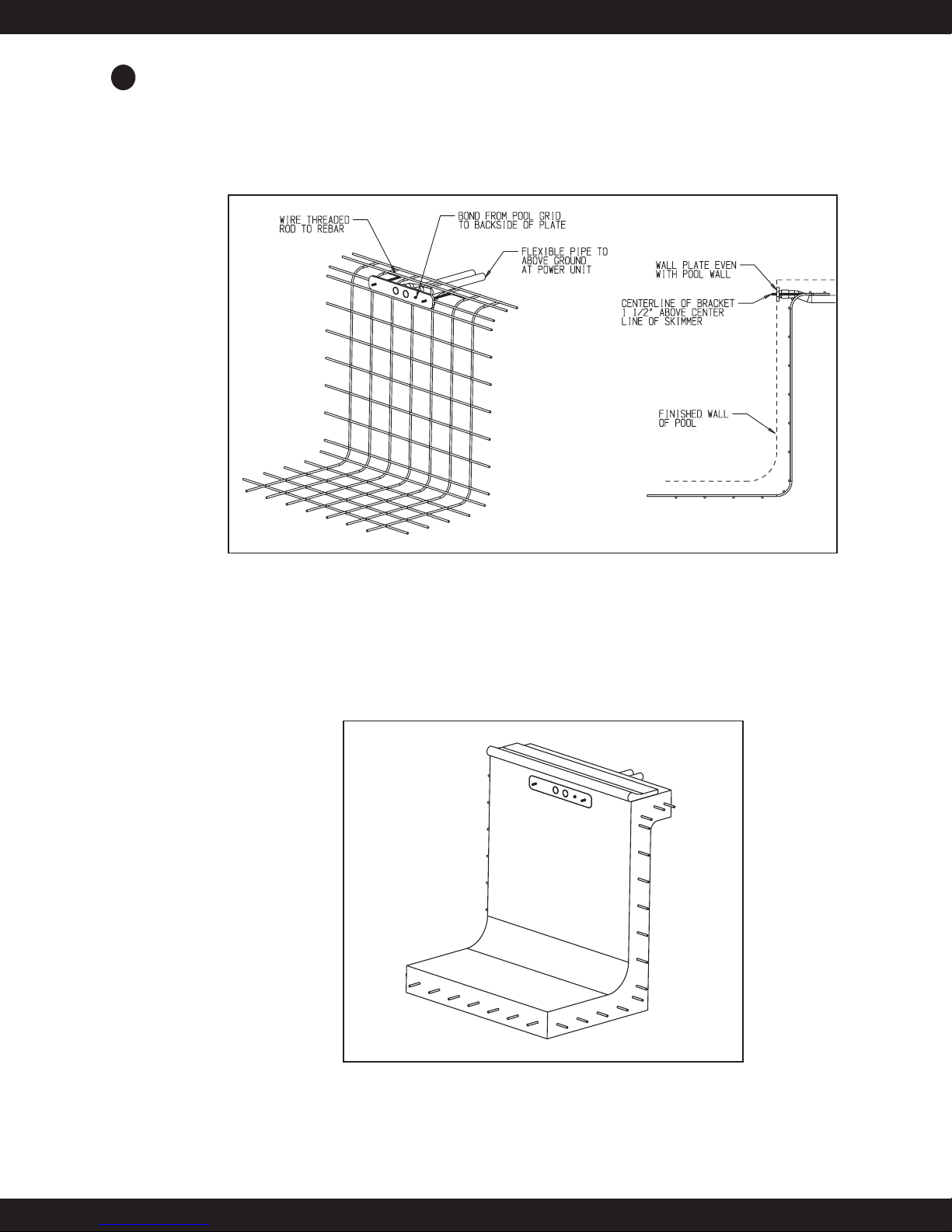
The bracket is to be installed into the pool wall as shown in Figure 4.2 so that the two mounting rods are 1-
W
1/2" above the intended waterline for the pool, which is typically halfway up the skimmer. (The bottom
edge of the Wall Mount Bracket will sit along the pool’s intended waterline.) The rods penetrate 1-1/4" to
1- 1/2" into the finished pool and will be used to hang the Wall Mount Fastlane. These rods must be tied
back to the rebar of the bond beam in the pool and, once encased in concrete, will serve as a suitable
hanger. Additionally, a #8 or larger, solid copper bonding wire must be connected from the pool bonding
grid to the bonding lug located on back of the wall mount bracket.
Fig. 4.2
Level and position the bracket so that the PVC surface of the bracket plate will be flush with the finished
surface of the pool wall as shown in Figures 4.2 and 4.3. The area below the bracket plate should be no
more than 5 degrees less than vertical down to at least 35" below the waterline. The Fastlane is 21" wide.
Consequently, the 21" section of wall where the bracket is located should be straight or near straight. Any
variations from this requirement should be discussed with your design representative. Additionally, it is imperative that the Fastlane not be installed less than 24" from an adjacent wall to allow for proper water
flow. Please refer back to Figure 2.1, Minimum Clearance Guidelines, for clarification.
Install two (2) complete 1" poly pipes back to the Hydraulic Power Unit or junction box. The two (2) 1"
poly pipes may be partially buried and/or covered with concrete. Care should be taken when rounding corners not to use tighter than 18" radius bends. It is imperative that this 1" poly pipe not be kinked given
the close tolerance of the fittings sliding through later (Section 9.4). Do not use couplers with this 1"
Fig. 4.3
4

F a s t l a n e®S w i m U n i t I n s t a l l a t i o n
W
poly pipe, but rather use a single length for each of the two hydraulic hoses that will run through them. The
goal is to provide an easy route for each of the two 3/8" hydraulic hoses — a route free of obstructions and
unlikely to bind. The hydraulic hoses may run on the surface outside the 1" poly pipe, but care must be
taken not to damage them. It is always best to use the 1" poly pipe provided as it protects the hydraulic
hoses from chafing as well as UV damage. The 1" poly pipe is chosen because of its slipperiness and the
ease with which the 3/8" hydraulic hose slides through it. At the same time, this 1" poly pipe can be easily
kinked which will make it difficult to slide the hydraulic hoses through later.
When planning for these two runs of 1" poly pipe, recognize that they penetrate the pool wall 1-1/2" above
the waterline and as a consequence will be flooded if the water level rises to that point. We strongly rec-
ommend that the 1" poly pipe rise to a point above which the water level will never rise to avoid any
potential flooding. This can be done during the 1" poly pipe run or back near the Power Unit. Tighten the
bracket liquid-tite fittings so that the 1" poly pipe is squeezed and water cannot leak around the 1" poly
pipe.
If you are concerned about subsidence and/or kinking, you may prefer to use a heavier 1-1/2" double run of
PVC flex pipe. To accomplish this, simply substitute the two couplings provided with the two (2) liquid-tite
fittings threaded into the PVC bracket, apply Teflon Tape to the couplings, and glue in the 1-1/2" PVC flex
pipe (refer to Photo 4.A.2).
3/8" Stainless Steel Mounting
Rod. Firmly secure these
rods to the rebar grid.
These 1-1/2" couplings may
be used if you choose to use
1-1/2" PVC flex pipe rather
than the 1" poly pipe as your
conduit to the Power Unit
and junction box.
Example of 1-1/2"
PVC Flex Pipe
Hang and secure Fastlane
on these SS threaded rods.
Bonding
Lug Set
Wall Mount Fastlane Bracket.
Install this side flush with the
finished pool surface.
Cover PVC end with duct tape
to prevent gunite from clogging
the PVC.
Photo 4.A.2
Attach SS bonding wire from
inside the Fastlane housing to
the bonding lug.
Bracket Plate
NOTE: The pool builder/installer must decide if they will be using 1" poly pipe or 1-1/2" PVC flex
pipe BEFORE spraying gunite. Once the 1" poly pipe or 1-1/2" PVC flex pipe has been run, cut, and
trenched, the gunite can be sprayed.
If installing the provided 1" poly pipe (standard installation), the Wall Mount Fastlane ships with two
(2) 24' 6" rolls of 1" poly pipe. From the rear side of the pool, feed each 1" poly pipe into the liquid-tite fittings and tighten the cord grip on the 1" poly pipe so that no water will pass between the 1" poly pipe and
the liquid-tite fitting. Unroll the 1" poly pipe to the location where the Power Unit will be located. The 1"
poly pipe is 6" shorter than the standard length of hydraulic hoses provided. As you run the 1" poly pipe, be
certain it does not kink. To ensure you have sufficient lengths of hydraulic hoses to make the necessary
connections to the Power Unit, cut off approximately 3' of each 1" poly pipe. The 1" poly pipe will need to
exit the ground near the Power Unit. If you find the 1" poly pipe is not long enough to reach the Power
Unit, a junction box and additional hydraulic hoses will need to be ordered and installed. In this case, DO
NOT CUT the length of the 1" poly pipe. Refer to Section 5 for additional information.
If installing the 1-1/2" PVC flex pipe, remove the two (2) 1-1/4" liquid-tite fittings from the wall mount
bracket. Thread and adhere with Teflon tape the two (2) 1-1/2" NPT male/slip female PVC fittings into the
wall mount bracket. Unroll the 1-1/2" PVC flex pipe from the wall mount bracket to the Power Unit. The
PVC flex pipe should exit the ground near the Power Unit. Each section of the PVC flex pipe should be no
longer than 21 feet. This will leave enough hydraulic hose to connect to the Power Unit. If you find that 21
feet of the PVC flex pipe is not long enough to reach the Power Unit, a junction box and additional hydraulic hoses will need to be ordered and installed. Refer to Section 5 for additional information.
5
F a s t l a n e®S w i m U n i t I n s t a l l a t i o n
4.B. Steel/Polymer Panel Pool with a Vinyl Liner
W
If the pool being constructed is steel/polymer panel with a vinyl liner, please follow the instructions below.
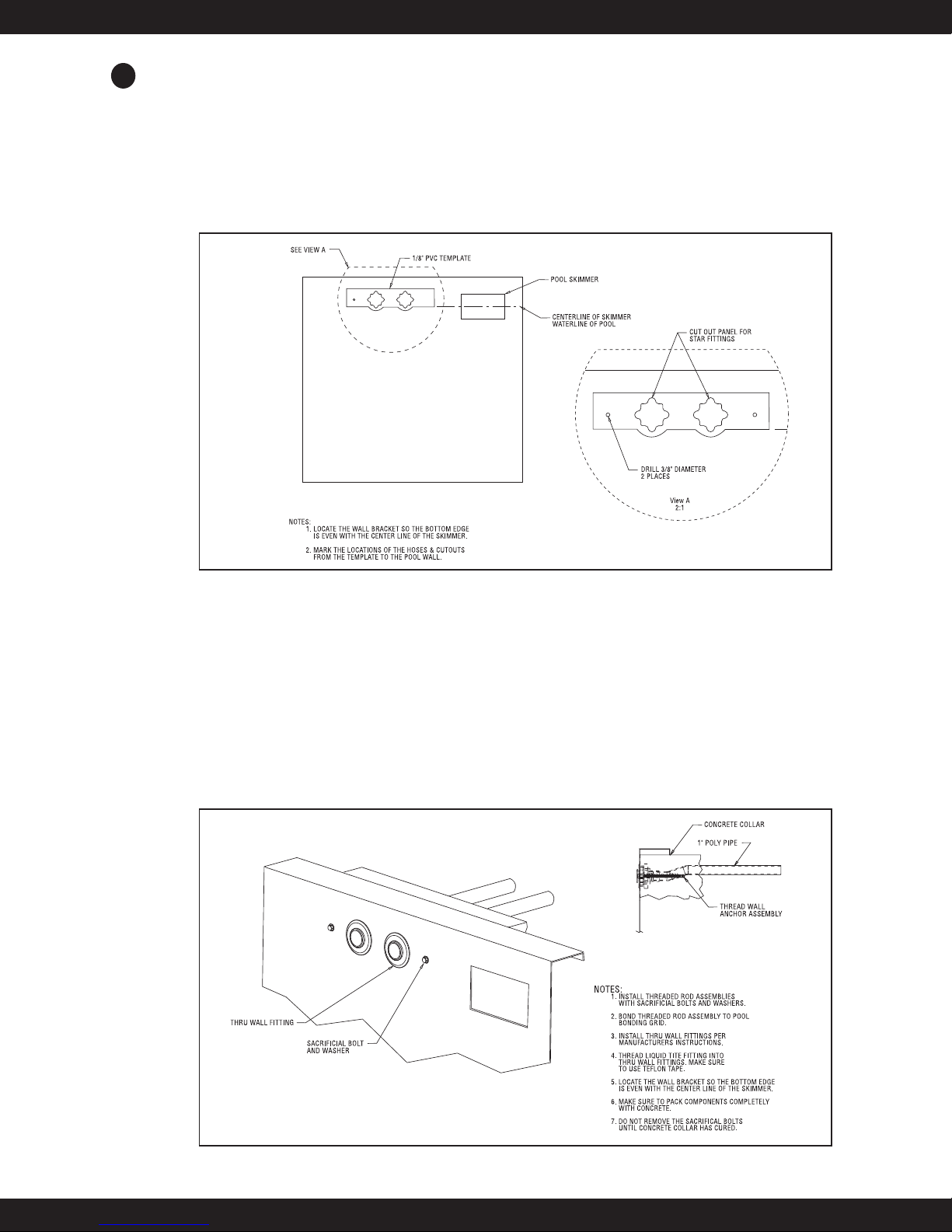
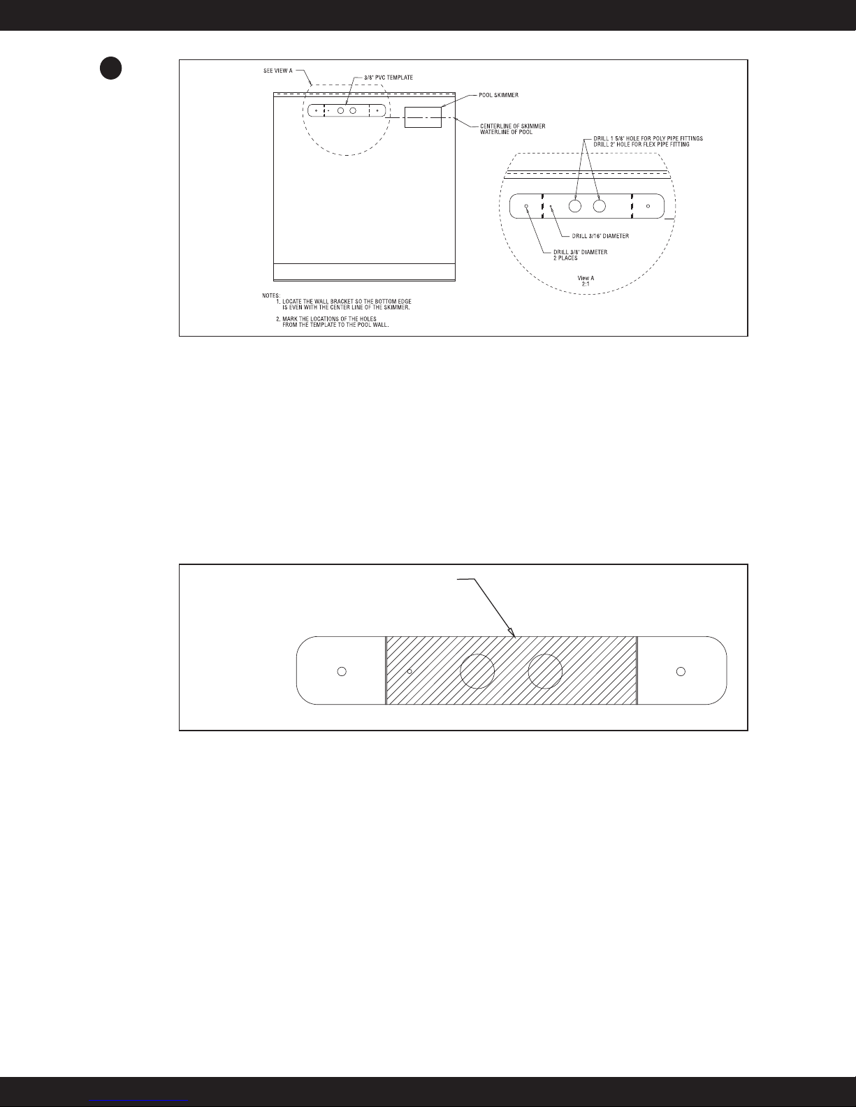
Remove the star thru-wall fittings and threaded rod pieces with hex coupling nut attachments from the 1/8"-
thick, grey PVC template. Position the PVC template where the Fastlane will attach to the pool wall and
align the bottom of the template with the expected water level in the pool (which will typically be located at
the centerline of the skimmer) as shown in Figure 4.4. Use duct tape, perhaps wrapped over the top flange,
to temporarily adhere the PVC template to the pool wall. Be certain that the PVC template is level in the
pool. Trace the outline of the star thru-wall fittings and threaded rod hole penetrations that are cut in the
PVC template onto the pool wall. Remove the duct-taped PVC template from the pool wall.
Fig. 4.4
Cut (or punch) the openings for the star thru-wall fittings and threaded rod holes. Install the star thru-wall
fittings with the holes for the cover at 12, 3, 6 and 9 (clock positions). Choose the appropriate adapters to
thread into the back of the star thru-wall fittings for the type of conduit that will be used for running the hydraulic hoses from the pool to the Power Unit. Use the provided 1" poly pipe with liquid-tite fittings or a
standard 1-1/2" PVC flex pipe with the provided 1-1/2" couplings. Refer to Section 5 for length of 1" poly
pipe or 1-1/2" PVC flex pipe. The threaded rod with hex coupling assembly must now be tightened against
the backside of the pool wall. The 3/8" jam nuts should be fastened on the threaded rod so that half of the
hex coupling is threaded onto the rod and the other half facing the poolside remains empty. Use the sacrificial 3/8" bolts and washers to thread into the hex coupling from the inside of the pool through the hole that
was previously drilled in the wall as shown in Figure 4.5. Tighten the bolts to secure the assembly to the
rear of the pool wall.
Fig. 4.5
6
F a s t l a n e®S w i m U n i t I n s t a l l a t i o n
W
Fig. 4.6
If using rebar in the pool’s collar, tie and bond the bent pieces of threaded rod into the bonded rebar grid.
If no rebar is being used, be sure to bond the threaded rod to the pool’s bonding grid.
Pour the concrete collar around the top flange of the pool securely encasing the threaded rod assemblies
and conduit adapters in place. Even if a bond beam is not being poured for the pool, it is essential for the
operation of the Fastlane that this assembly be securely anchored in concrete. After the concrete has cured,
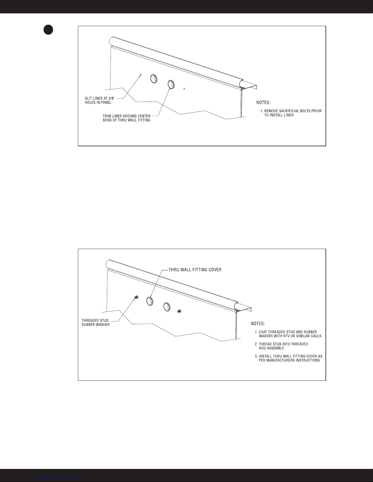
remove the 3/8" bolts and install the pool liner. Note: Before beginning the liner installation, be sure to note
the orientation of the star thru-wall holes at 12, 3, 6 and 9 (clock positions) as they will be hidden once the
liner is hung. (Refer to Figure 4.6.) Make sure there is some water in the bottom of the pool, giving weight
to the liner and pulling it tight, before the holes for the star thru-wall fittings and threaded rod pieces are
cut. When the liner is tight enough, cut the holes. Note: Keep the holes for the threaded rod as small as possible. Attach the faceplate to the star thru-wall fittings, coat the threaded stud and rubber washer with RTV
or similar caulk, and thread the stub into the threaded rod assembly. (Refer to Figure 4.7.)
Fig. 4.7
4.C. Fiberglass Pool Installation
If the pool being constructed is fiberglass, please follow the instructions below.
Remove the liquid-tite fittings, bonding lug assembly, and threaded rod pieces from the 3/8"-thick, grey
PVC bracket plate which serves as a template. Position the PVC template where the Fastlane will attach to
the pool wall and align the bottom of the PVC template with the expected water level in the pool (which
will typically be located at the centerline of the skimmer). Refer to Figure 4.8. Use duct tape, perhaps
wrapped over the top flange, to temporarily adhere the PVC template to the pool wall. Be certain that the
PVC template is level in the pool. Trace the outline of the liquid-tite fittings, bonding lug, and threaded rod
hole penetrations that are cut in the PVC bracket onto the pool wall.
7
CUT BRACKET BETWEEN NOTCHES
DISCARD MIDDLE SECTION
W
F a s t l a n e®S w i m U n i t I n s t a l l a t i o n
Fig. 4.8
Remove the duct-taped PVC template from the pool wall. Drill the openings for the liquid-tite fittings,
bonding lugs and threaded rod holes. Determine if the provided 1" poly pipe or 1-1/2" PVC flex pipe will
be used as conduit in which to run the hydraulic hoses from the pool to the Power Unit.
If using the provided 1" poly pipe:
• From the rear of the pool, attach the liquid-tite fitting to the fiberglass pool wall and firmly tighten it to
the pool wall. Silicone may be used to get a tight seal.
• Feed the 1" poly pipe into the liquid-tite fittings from the rear of the pool, and tighten the fittings on the
poly pipe (from the rear of the pool) to prevent water from passing between the poly pipe and the fittings.
• Cut the ends of the 3/8"-thick, grey PVC bracket plate along the score lines. These two ends will act as
washer/bolt heads against the back of the pool wall. Discard the center section as shown in Figure 4.9.
Fig. 4.9
• Thread the 3/8" threaded rod into the holes in the cut off end pieces, so that once permanently installed, 11/4" to 1-1/2" of threaded rod will penetrate beyond the pool wall surface. Refer to Figure 4.10. To help
prevent cross threading, thoroughly clean the exposed end of the threaded rods of any excess fiberglass
before threading nuts onto the threaded rods.
• Attach the bonding lug to the rear of the pool and thread the screw for the bonding lug through the hole in
the pool wall. The bonding lug screw should penetrate at least a 1/2" into the pool wall when permanently
installed. A #8 or larger, solid copper bonding wire must be connected from the pool bonding grid to the
bonding lug located on the back of the wall mount bracket
• Apply the provided silicone adhesive to the side of the PVC bracket plate that will mate against the pool
wall to ensure that the seal is watertight.
• Feed the poolside ends of the threaded rods through the holes drilled in the fiberglass pool wall, and using
the provided washers and jam nuts, secure the rod tightly to the pool wall. Leave nuts and washers attached until silicone cures.
8
 Loading...