

Page 1

MODEL 136
DC AMPLIFIER
INSTRUCTION
MANUAL
San Juan Capistrano, California, U.S.A.
IM136
Revision D
30 September 1999
Page 2

ENDEVCO MODEL 136 DC AMPLIFIER
INSTRUCTION MANUAL
TABLE OF CONTENTS
SECTION 1: GENERAL DESCRIPTION
1.1 INTRODUCTION.........................................................................................................2
1.2 DESCRIPTION............................................................................................................3
1.3 FUNCTIONAL CHARACTERISTICS..........................................................................3
1.4 KEY FEATURES.........................................................................................................3
SECTION 2: INSTALLATION, FRONT AND REAR PANEL DESCRIPTION AND OPERATION
2.1 INSTALLATION...........................................................................................................4
2.2 FRONT PANEL DESCRIPTION..................................................................................5
2.3 REAR PANEL DESCRIPTION....................................................................................6
2.4 OPERATION...............................................................................................................12
2.4.1 Channel Selection.......................................................................................................12
2.4.2 Normal Mode............................................................................................................... 12
2.4.3 Query/Programming Mode..........................................................................................13
2.4.4 Function Selection.......................................................................................................13
2.4.5 Excitation Voltage........................................................................................................14
2.4.6 Sensor Sensitivity........................................................................................................ 14
2.4.7 Output Scaling............................................................................................................. 14
2.4.8 Low Pass Filter............................................................................................................ 15
2.4.9 Auto Zero.....................................................................................................................15
2.4.10 Shunt Calibration......................................................................................................... 15
2.4.11 Monitoring State.......................................................................................................... 16
2.4.12 Special Modes............................................................................................................. 17
2.4.13 Fault Indication............................................................................................................ 20
2.4.14 RS-232 Operation........................................................................................................20
2.4.15 Filter Options and Installation......................................................................................20
2.4.16 Sample Set Up............................................................................................................ 21
2.5 RACK MOUNTING KIT ............................................................................................... 23
SECTION 3: ROUTINE MAINTENANCE AND HANDLING
3.1 INTRODUCTION.........................................................................................................24
3.2 FACTORY SERVICE...................................................................................................24
3.3 ORDERING INFORMATION AND ACCESSORIES...................................................25
SECTION 4: APPENDIX
PAGE
1. Model 31875-XXXX-O Filter Data Sheet 26
2. Serial Communication......................................................................................................... 27
LIST OF FIGURES
FIGURES
1. Front Panel.................................................................................................................. 5
2. Rear Panel (AC Input power)......................................................................................6
3. Rear Panel (DC Input power)......................................................................................7
4. Block Diagram, Model 136..........................................................................................7
5. RS-232 Serial Communication Block Diagram............................................................8
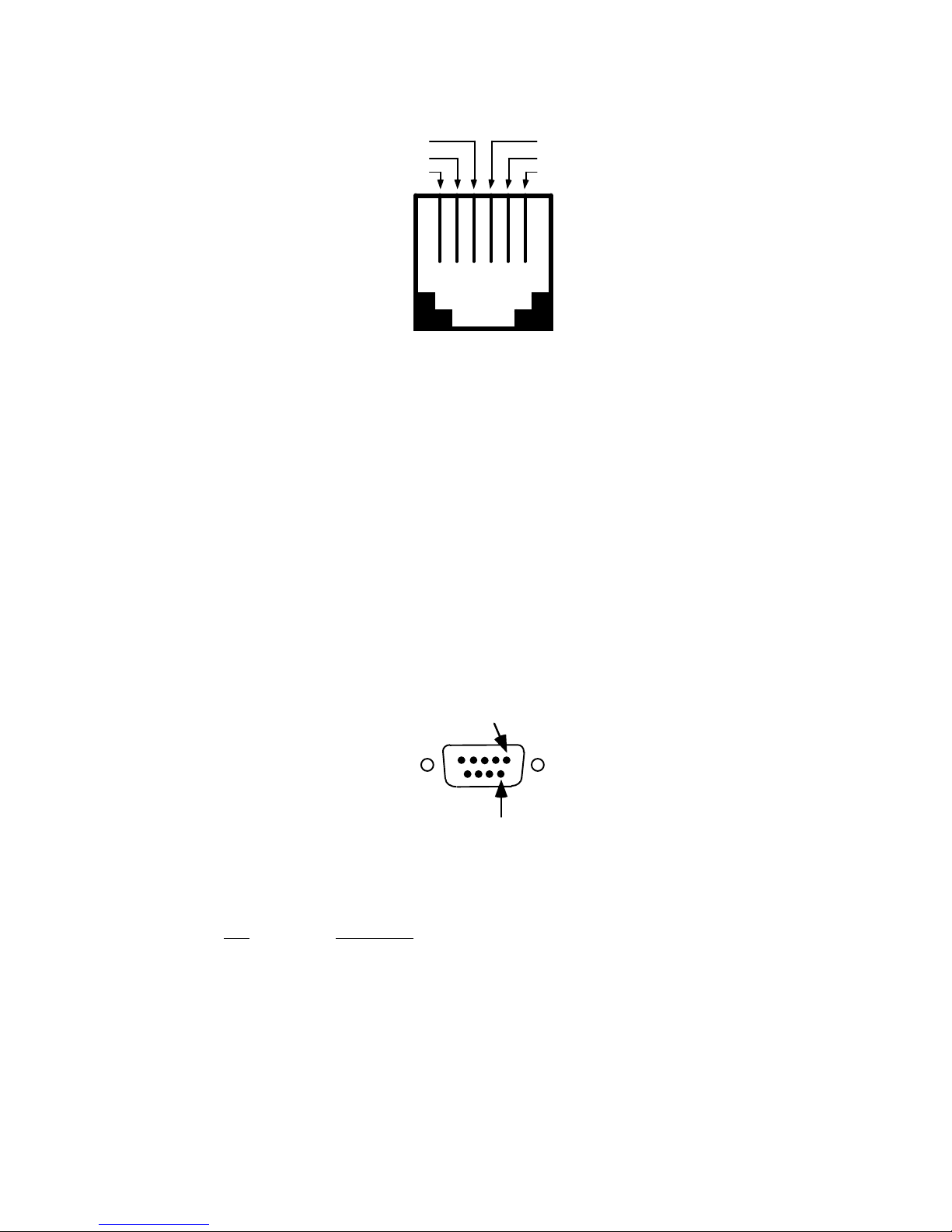
6. RJ-11 Mod Jack, Front view........................................................................................9
7. 9 Pin "D" Input Connector Pin Assignment..................................................................9
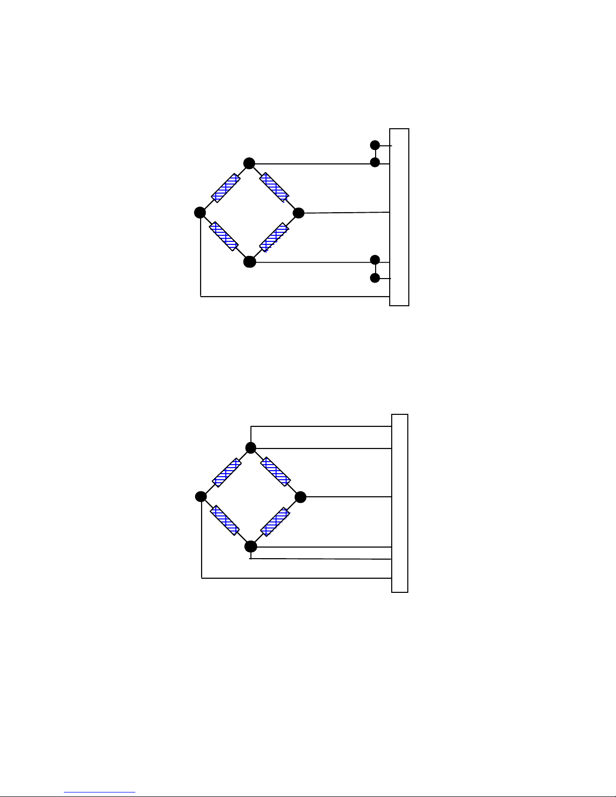
8. Typical Bridge Connection...........................................................................................11
9. Typical Bridge Connection with Remote Sensing........................................................11
10. Filter Module Location.................................................................................................21
IM136
Page 1
Page 3

ENDEVCO MODEL 136 DC AMPLIFIER
INSTRUCTION MANUAL
SECTION 1: GENERAL DESCRIPTION
1.1 INTRODUCTION
ENDEVCO has remained a leader in the vibration measurement field since 1951, and has
contributed many firsts in vibration sensor design. These include: the first piezoelectric
accelerometer capable of continuous operation from cryogenic temperatures up to +750°F,
the first shear design accelerometer and the world's smallest piezoelectric accelerometer. To
support a broad family of vibration transducers, ENDEVCO has provided a wide variety of
signal conditioners, including the first transistorized charge amplifier, the first computerprogrammable charge amplifier and the first airborne vibration monitoring system that is
based on a true digital tracking filter.
SIGNAL CONDITIONERS
To support the use of its sensors in large scale testing, ENDEVCO has developed several
generations of signal conditioner systems. Until recently, a state-of-the-art vibration
laboratory set up consisted of a rack of manually controlled signal conditioners. These signal
conditioners have manually controlled switches and knobs, to set full scale ranges, sensitivity
and filter corners and the set up information is recorded by hand.
COMPUTER CONTROLLED SIGNAL CONDITIONERS
To eliminate the risk of incorrect amplifier settings, ENDEVCO has pioneered the concept of
computer controlled signal conditioners. The first generation was the Multi-channel Amplifier
Control system (MAC). The second generation was the Computer Controlled Amplifier
Systems (CCAS). The CCAS family consists of five different systems that use the same rack
and digital interface assemblies with different analog boards. These units receive their setup
commands over an IEEE-488 interface bus from a computer/controller, so that tests can be
pre-programmed. In addition, these units provide comprehensive self-test and self-calibration
capabilities, which greatly improves the reliability of the test data. User feedback is indicated
that these units pay for themselves quickly by shortening test cycles, preventing retests and
eliminating over-testing.
MANUAL/COMPUTER CONTROLLED SIGNAL CONDITIONERS
The experience gained in the first two generations of computer controlled amplifiers has now
been applied to a third generation product line: the programmable bridge conditioner and the
programmable laboratory signal conditioner. These units are independently controlled and
each unit contains its own power supplies for single channel integrity.
The Model 136, has both manual and computer programmable features. This DC Amplifier is
an example of Endevco's commitment to improving the state-of-the-art in sensory
measurements. The new generation is smaller with more features and will continue to be
expanded to meet an ever widening range of application requirements.
IM136
Page 2
Page 4

ENDEVCO MODEL 136 DC AMPLIFIER
INSTRUCTION MANUAL
1.2 DESCRIPTION
The ENDEVCO
use with Piezoresistive (PR) accelerometers, Variable Capacitance (VC) accelerometers, and
pressure transducers. The unit provides an AC output voltage proportional to the voltage
input, and is designed to be powered by 90-240 VAC {with a 9-18 VDC option also
available(136-1)}.
The Endevco Model 136 has a fixed 10 Hz 4-pole Butterworth high-pass filter that can be
selected or bypassed. It has a plug-in 4-pole low pass filter whose corner can be set by an
internal header module, which offers multiple corner frequencies. {See Section 2.4.15 Filter
Options and Installation and Appendix 1, (Endevco Model 31875-XXXX-O)}.
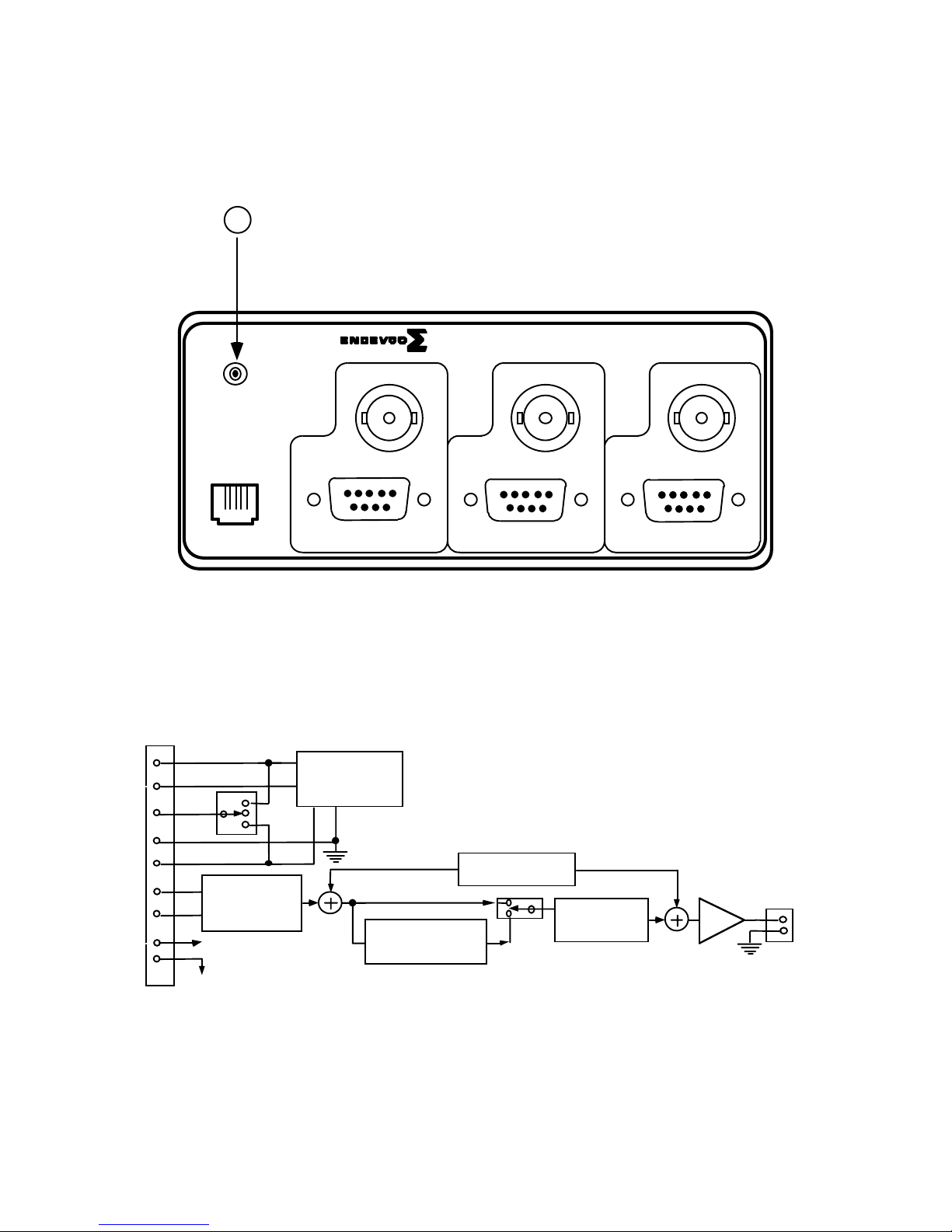
Figure 4 shows a detailed circuit block diagram for the unit.
Filter options are available to meet the filter corner requirements for J211 and ISO6487. The
specific filter corners available are: 300 Hz and 1,650 Hz. {See Section 2.4.15 Filter Options
and Installation and Appendix 1, (Endevco Model 31875-XXXX-O)}.
Up to three (3) Model 136 units can be installed in a 19” rack using ENDEVCO Model 31979
Rack Mounting Kit.
1.3 FUNCTIONAL CHARACTERISTICS
The Endevco Model 136 can be manually programmed from the front panel (Figure 1) by
means of a “Select Channel” push-button, three (3) “Channel LEDs”, a “Select Function”
push-button, seven (7) “Function LEDs” indicating which function has been selected by the
“Select Function” push-button (referred to in this document as the “function LEDs”), a four (4)
character LED display to show the state of each function, four (4) “EDIT” push-buttons to
change the entries in the LED display, and three (3) LEDs indicating if there are any faults in
any of the channels (referred to in this document as the “Fault LEDs”).
The unit has two modes of operation: (1) Normal and (2) Query/Programming. In the Normal
mode of operation, the unit can be in (a) Monitoring State, or (b) No-Monitoring State. While in
the Normal mode of operation, the selected state will apply to all three channels
simultaneously.
The unit will store the settings for all of the functions in its internal memory and at power-up it
will automatically restore the settings from the last session.
1.4 KEY FEATURES
The following are some of the highlight features:
• Three-channel DC Differential Voltage Amplifier
• 100 kHz Bandwidth (-3dB corner)
• 10 Volt Full Scale Output
• Auto-Zero and Shunt Calibration
• Four Selectable Excitation Voltage Levels
• Gain range from 0 to 1000
• RS-232 Serial Interface
• Optional Low Pass filter corners available ( standard default filter is
a 10 kHz Butterworth)
• Filter Options Available for J211 and ISO6487 Requirements
®
Model 136 DC Amplifier is a three-channel signal conditioner designed for
IM136
Page 3
Page 5

ENDEVCO MODEL 136 DC AMPLIFIER
INSTRUCTION MANUAL
SECTION 2:
INSTALLATION, FRONT AND REAR PANEL DESCRIPTION AND OPERATION
2.1 INSTALLATION
2.1.1 UNPACKING
The Endevco Model 136 DC Amplifier is shipped along with its instruction manual in one
package. Carefully unpack and check all items for shipping damage. Report any obvious
damage to the carrier immediately. If the shipping container or cushioning material is
damaged, it should be kept until the contents of the shipment have been checked
mechanically and electrically. In any case, save the original packing materials for future
shipments of the hardware. Check each item of the shipment against the packing list. Notify
Endevco of any discrepancy.
The equipment has been inspected and tested at the factory and is ready for operation when
received.
Unpack the Model 136 and set it on a level, firmly supported surface. Verify that all standard
and ordered optional accessories are included.
2.1.2 FILTER MODULE INSTALLATION OR REPLACEMENT
For filter module installation or replacement, see Section 2.4.15 of this manual.
2.1.3 POWERING ON THE UNIT
For AC input power, install the EW599 power cord into the rear power connection of the
Model 136. (See Figure 2, Rear Panel, AC input power.)
For optional DC input power (Model 136-1), install the +9 to +18 VDC input power source into
the DC input power connector, located on the rear of the Model 136-1. (See Figure 3, Rear
Panel, DC input power.)
2.1.4 KEY PARAMETERS
The standard unit has an AC input voltage requirement from 90 to 264 VAC, 50 to 60 Hz
(Universal Input). No jumpers or changes to the unit's power supply are required for input
power meeting this requirement.
The Model 136 "-1" option is a DC powered version that accepts an input voltage range from
+9 to +18 VDC.
Power dissipation for either the standard or -1 version is 9 watts typical.
1. Physical Characteristics
Dimensions 5.57" x 2.52" x 12"
Weight 4 lbs typical
Case Material Black Aluminum Cover, Medium Gray Plastic Bezel
Current 1 Amp maximum
IM136
Page 4
Page 6
ENDEVCO MODEL 136 DC AMPLIFIER
INSTRUCTION MANUAL
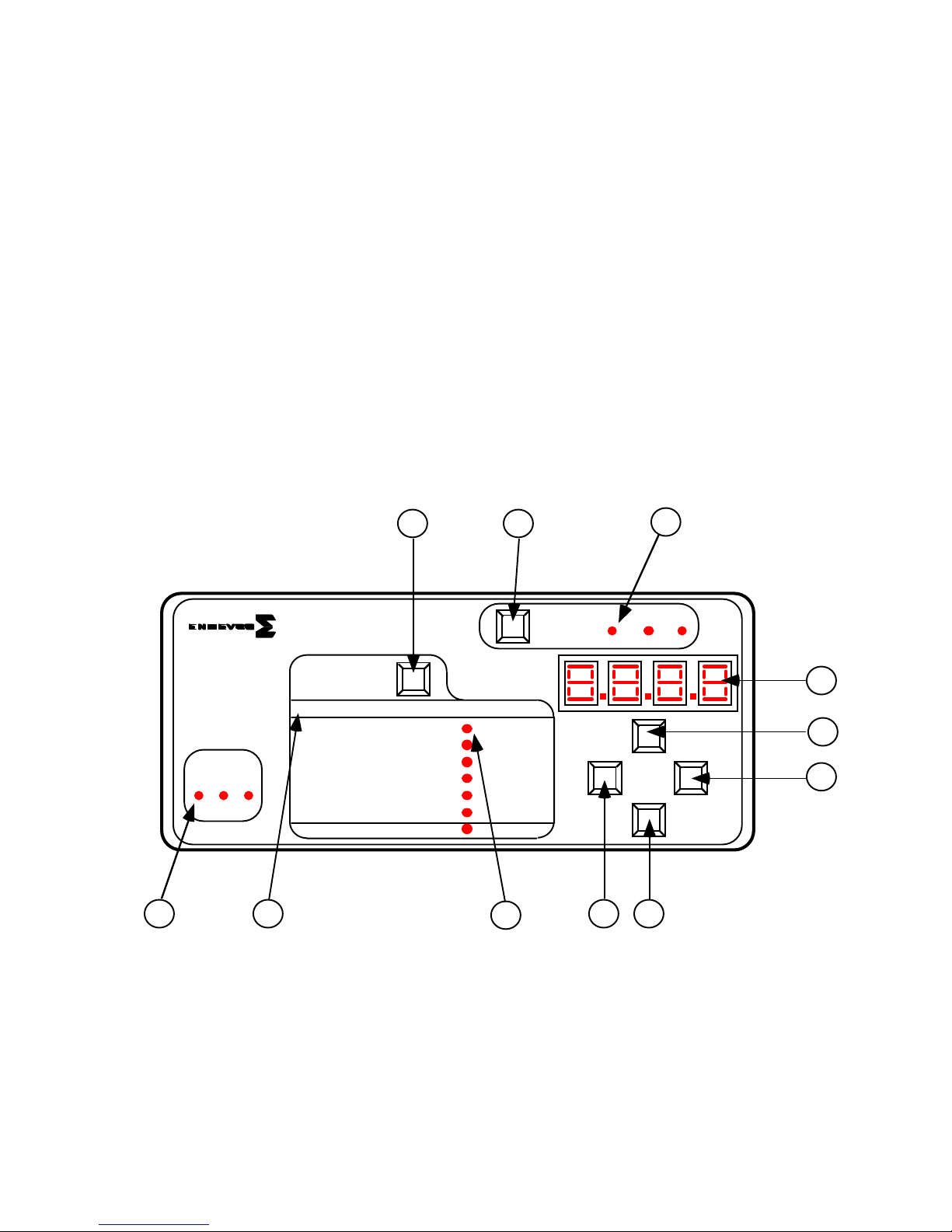
2.2 FRONT PANEL DESCRIPTION
Shown in Figure 1 is the Model 136 front panel. The front panel is a Mylar overlay, adhesively
attached to the front panel aluminum plate. The Mylar overlay has cutouts for the six push
buttons, and clear windows for 13 LED's and the 4-digit panel meter. Each push button and
LED are described as follows:
Figure 1 Item 1, is the "Select Function" push button that controls the functions listed below it.
Pressing the Select Function push button scrolls through the LED's. The function selected can
be modified while the LED is flashing, located to the right of the associated function.
Figure 1 Item 2, is the "Select Channel" push button. Pressing this push button sequentially
selects channels one to three, which is used for set up and display of data on the digital panel
meter. The appropriate channel's LED remains illuminated until a different channel is selected.
Figure 1 Item 3, is the LED for channel one of the three channel unit. The LED illuminated
corresponds to the channel that is actively being set up or data displayed on the DPM.
Figure 1 Item 4, is the digital panel meter (DPM). The DPM displays alpha-numerics for the
appropriate "Select Channel" selected and is used to display the channel set up and for actual
data display. The DPM has an accuracy of ± 10%. (See Section 2.4, Operation and subsections contained, for specific push button abilities.)
Edit
78
3
4
5
6
DC Differential
Voltage Amplifier
Model 136
Channel
1 2 3
FAULT
1011
1
Select Function
FUNCTION OFF LED ON
Voltage Exc. (V) OFF ON
Sensitivity (mV/ EU) Edit
Output Scaling (mV/ EU) Edit
LP Filter ( kHz) OFF ON
Auto -Zero OFF ON
Shunt Calibration OFF ON
Monitoring State OFF ON
9
2
S e l e c t
Cha n ne l
123
Figure 1
Figure 1 Items 5, 6, 7, and 8 correspond, respectively to the "Up", "Right", "Down" and "Left"
Edit push buttons. These push buttons are used to change the entries on the digital panel
meter and are used in conjunction with the appropriate "Select Function" parameter to be
programmed. (See Section 2.4, Operation and sub-sections contained, for specific push
button abilities.)
Figure 1 Item 9, is one of seven Function parameters LED's that is selectable/programmable.
The flashing LED identifies the function that is actively capable of being set up or modified at
that time.
IM136
Page 5
Page 7
ENDEVCO MODEL 136 DC AMPLIFIER
INSTRUCTION MANUAL
Figure 1 Item 10, is a list of "Functions" that are programmable for each channel, which are
selected by the "Select Function" push button and are set up or modified with the four "Edit"
push buttons.
Figure 1 Item 11, are the "Fault" LED's. The illuminated LED indicates that particular channel
is in the ISOTRON mode, the current excitation is on and there exists a short or open circuit
for the input.
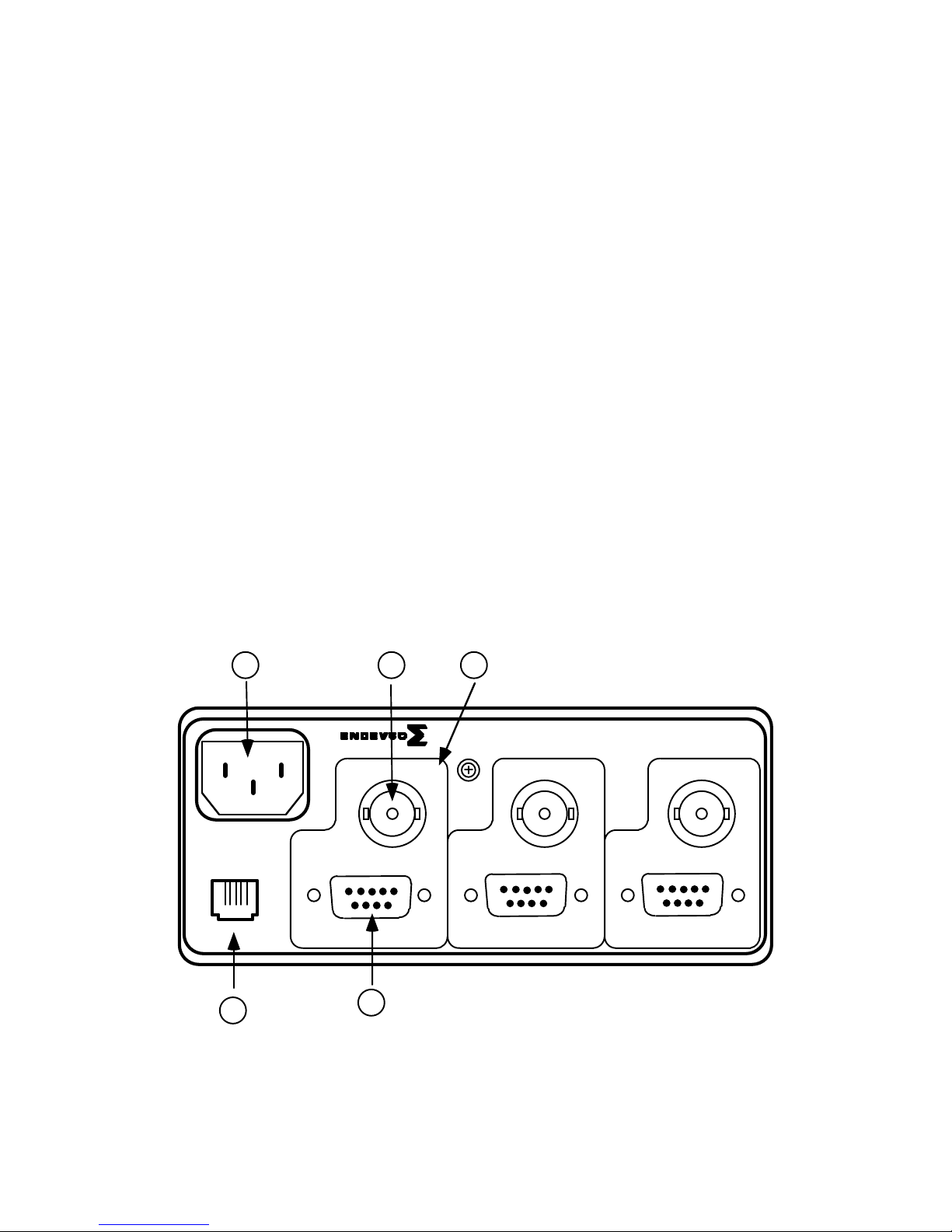
2.3 REAR PANEL DESCRIPTION
Shown in Figure 2 is the rear view of the Model 136.
Figure 2 Item 1, is the standard AC input power connector. The supplied Endevco power
cable, PN EW599, is connected to this connector. (Note: The acceptable input power is 90
to 264 VAC, 50/60 Hz. No jumpers or adjustment is required for input voltages within this
range. The unit doe not have an on/off power switch. )
Figure 2 Item 2, is a standard BNC connector used for the output from each channel.
Figure 2 Item 3, is a blocked-off area for a single channel, depicted is channel 3. The
channels correspond to the front panel channels 1, 2, and 3.
Figure 2 Item 4, is the input connector. This is a standard 9-pin "D" Female connector.
Figure 2 Item 5, is the RJ-11 Modular Jack, Front View. (Please see Figures 5, 6 and Section
2.4.7. for the RS-232 information.)
1
2 3
Model 136: DC Differential Voltage Amplifier
100/115/230V~
.5/.5/.25A
50/60Hz
RS-232
5
CHANNEL 3
OUTPUT
4
Input and ExcitationInput and Excitation
CHANNEL 2
OUTPUT
CHANNEL 1
OUTPUT
Input and Excitation
Figure 2
IM136
Page 6
Page 8
ENDEVCO MODEL 136 DC AMPLIFIER
INSTRUCTION MANUAL
Figure 3 is the optional Model 136-1 rear panel view. Item 1, is the DC input power
connector. The input power requirements are: 9 to 18 volts DC and a maximum current of 1
amp. The input connector is a 760 Plug style.
1
Model 136-1: DC Differential Voltage Amplifier
9-pin "D" Connector
1
7
3
8
6
5
4
9
2
9-18 VDC
RS-232
PSEN +
P +
RSH
P -
PSEN -
S +
Instrumentation
Amplifier
S-
(1, 10, 100)
Guard
CHANNEL 3
Input and Excitation
Excitation
Voltage
(0,5, 10, 15 VDC)
4-pole Butterworth
Low-Pass Filter
CHANNEL 2
Input and Excitation
Figure 3
Offset Adjustment
OUTPUTOUTPUT
Input and Excitation
Programmable
Gain: 0 to 10
CHANNEL 1
OUTPUT
BNC
-15 VDC
Figure 4 is the Model 136 block diagram.
Figure 4
IM136
Page 7
Page 9
ENDEVCO MODEL 136 DC AMPLIFIER
INSTRUCTION MANUAL
To PC
Controller
DB9F
3
2
5
EJ807
Adapter
RJ11 RJ11
4
Tx
2
Rx
5Gnd
RJ11
4
2
5
4
2
5
133 or 136
Rx
3Channel
Tx
Amplifier
133 or 136
Rx
3Channel
Tx
Amplifier
Figure 5
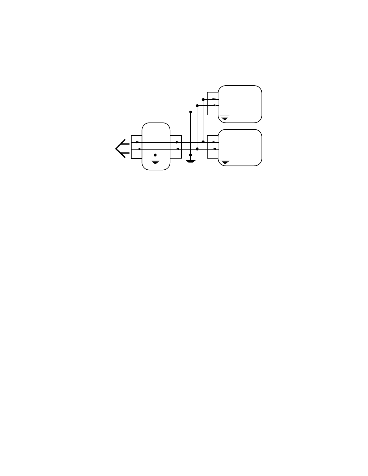
Figure 5 is the block diagram for the RJ-11 RS-232 computer control connector.
IM136
Page 8
Page 10
ENDEVCO MODEL 136 DC AMPLIFIER
INSTRUCTION MANUAL
Not Used
TX
Analog Ground
123456
Figure 6
Figure 6 is the RJ-11, Modular Jack, Front View RS-232
RJ11 Pin Assignment:
Pin 1: Analog Ground
Pin 2: TX (connects to RX in computer)
Pin 3: Not Used
Pin 4: RX (connects to TX in computer)
Pin 5: Digital Ground
Pin 6: Digital Ground
Pin 1
RX
Digital Ground
Digital Ground
9 Pin "D" Input Connector Pin Assignment
P/N
Pin 1: Psen+ Excitation Sense
Pin 2: -15 VDC
Pin 3: Shunt Cal (RSH)
Pin 4: S- Sensor Input
Pin 5: S+ Sensor Input
Pin 6: Psen- Excitation Sense
Pin 7: P+ Excitation Voltage
Pin 8: P- Excitation Voltage
Pin 9: Guard/Shield
Description
Pin 6
Figure 7
IM136
Page 9
Page 11

ENDEVCO MODEL 136 DC AMPLIFIER
INSTRUCTION MANUAL
WARNING OF POSSIBLE CATASTROPHIC DAMAGE TO SENSORS
Up to 24 VDC may be temporarily present on the excitation lines (P+: pin 7, and P-: pin 8) during the first
12 seconds after applying power to the unit. To avoid this, the excitation sense lines (PSEN+: pin 1,
PSEN-: pin 6) must be connected as shown in figure 5 or figure 6. This temporary high voltage may
damage the sensor connected to the input of the unit.
The Model 136 is designed to restore the last excitation voltage programmed into it at power-up. Sensors
could be damaged if the unit was previously set to an excitation voltage (i.e. 15 V) that is higher than the
maximum excitation voltage rating for the sensor.
If the user is not sure what excitation voltage was last selected, the Model 136 should be powered-up and
the excitation voltage verified prior to connecting a sensor to the unit.
IM136
Page 10
Page 12
ENDEVCO MODEL 136 DC AMPLIFIER
INSTRUCTION MANUAL
Model 136
9 Pin "D" Connector
PS EN +
P
+
S+
P-
PS EN
S-
Figure 8
Typical Bridge Connection
PS EN
+
P+
1
7
5
8
-
6
4
1
7
S+
P-
PS EN -
S-
Figure 9
Typical Bridge Connection With Remote Excitation Sensing
5
8
6
4
IM136
Page 11
Page 13

ENDEVCO MODEL 136 DC AMPLIFIER
INSTRUCTION MANUAL
2.4 OPERATION
The Endevco Model 136 can be manually programmed from the front panel (See Figure 1) by
means of a “Select Channel” push-button, three (3) “Channel LEDs”, a “Select Function”
push-button, seven (7) “Function LEDs” indicating which function has been selected by the
“Select Function” push-button (referred in this document as the “function LED's”), a four (4)
character LED display to show the state of each function, four (4) “EDIT” push-buttons to
change the entries in the LED display, and three (3) LEDs indicating if there are any faults in
any of the channels (referred in this document as the “Fault LED's”).
The unit has two modes of operation: (1) Normal and (2) Query/Programming. In the Normal
mode of operation, the unit can be in (a) Monitoring State, or (b) No-Monitoring State. While in
the Normal mode of operation, the selected state will apply to all three channels
simultaneously.
The unit will store the settings for all of the function in its internal memory and at power-up it
will automatically restore the settings from the last session.
2.4.1 Channel Selection
The user selects which channel is being programmed by pressing the “Select Channel” push-
button. Each press of the “Select Channel” push-button will sequentially turn-on one of the 3
“Channel LED's” located to the right of the “Select Channel” push-button indicating the
channel number selected for programming.
The unit will remain in the selected mode/state of operation (normal or query/programming)
while pressing the “Select Channel” push-button.
2.4.2 Normal Mode
1. Monitoring State
In the Monitoring state of operation the unit takes an RMS reading of the signal present at the
output of the selected channel every 500 mSec and displays the value on the LED display in
Engineering Units (EU: the physical variable in RMS being measured by the transducer) or V
out in RMS. This state is activated by selecting either the "EU" or “V out” entry in the "Monitor"
Function selection.
Pressing the “Select Channel” push-button while in the Monitoring state allows the user to
quickly view (sequentially) the signal levels at the output of each channel.
2. No-Monitoring State
The No-Monitoring state allows for low noise operation. This is accomplished by not taking
A/D readings from the outputs, and by placing the CPU in idle mode in order to minimize
power consumption and digital noise in the unit. The LED display will be turned OFF. This
state is activated by selecting the "OFF" entry in the "Monitor" Function selection.
IM136
Page 12
Page 14

ENDEVCO MODEL 136 DC AMPLIFIER
INSTRUCTION MANUAL
2.4.3 Query/Programming Mode
The Query/Programming Mode allows for manual programmability and querying of the
programmable functions. This Mode is activated by pressing the “Select Function” pushbutton.
A function is queried by selecting it using the “Select Function” push-button. The current
setting for the selected function will be displayed on the LED display. The entry in the LED
display is edited by using the four EDIT push-buttons (located just below the LED display.)
The new setting will be implemented into the unit hardware as soon as the entry shown on the
LED display is modified. The unit returns to the Normal mode of operation after 20 seconds of
inactivity (no push-buttons pressed) or after pressing the “Select Function” push-button while
the “Monitoring State” function LED is flashing.
2.4.4 Function Selection
The user selects which function is being programmed by pressing the “Select Function” push-
button. Each press of the “Select Function” push-button will sequentially make one of the
“Function LEDs” blink indicating the function is selected for programming.
The first press of the “Select Function” push-button selects the function LED that was selected
the last time that the unit was in Query/Programming Mode. The selected Function LED will
be blinking and the current setting will be displayed on the LED display. Each additional press
of the “Select Function” push-button selects the next function (corresponding Function LED
blinking) and the corresponding setting is displayed on the LED display. Pressing the “Select
Function” push-button while the “Monitoring State” function LED is flashing puts the unit
immediately back into Normal mode.
The following functions can be selected for programming: (1) Excitation Voltage, (2) Sensor
Sensitivity, (3) Output Scaling, (4) Low Pass Filter, (5) Auto-Zero, (6) Shunt Calibration, and
(7) Monitoring State.
When the function is selected, the corresponding “Function LED” will stay blinking until the
“Select Function” push-button is pressed again to select the next function. The LED display
will show the current setting for the selected function. The EDIT keys can then be used to
change the setting. If no buttons are pressed after 20 seconds, then the “Function LED” will
stop blinking and the unit will return to the normal mode of operation (monitoring or nonmonitoring state).
Each “Function LED” will remain OFF or ON during the normal mode of operation (and also
immediately after selecting the next function) depending on the setting selected by the user
for the corresponding function.
The user can select a function, and then use the “Select Channel” push-button to view/edit the
current setting for the selected function for each channel.
IM136
Page 13
Page 15

ENDEVCO MODEL 136 DC AMPLIFIER
INSTRUCTION MANUAL
2.4.5 Excitation Voltage
This function is used to enable/disable the excitation voltage and also to set the amplitude of
the excitation voltage. The up-down EDIT keys are used to select the input type. The following
messages will be shown sequentially on the LED display each time the up-down EDIT keys
are pressed: (1) “0.00”, (2) “5.00”, (3) “10.00”, and (4) “15.00”.
1. "0.00": Set excitation voltage level to 0 VDC.
2. "5.00": Set excitation voltage level to 5 VDC.
3. "10.00": Set excitation voltage level to 10 VDC.
4. "15.00": Set excitation voltage level to 15 VDC.
The excitation will be set to the desired voltage level after the “Select Function” key is pressed
or after the unit returns to the normal mode of operation.
The “Function LED” corresponding to the Excitation Voltage function will remain OFF during
the normal mode of operation if the user selected the “0 VDC” setting (excitation disabled).
The function LED will remain ON if the Excitation Voltage was enabled by selecting any of the
other settings.
2.4.6 Sensor Sensitivity
This function selection provides for programming the sensitivity of the transducer (in mV/EU).
The Endevco Model 136 uses this information to determine the gain needed to achieve the
required output scaling. The left-right EDIT keys select the number position in the LED
display, and the up-down EDIT keys increment or decrement the selected number.
The user can enter four (4) significant digits ranging from 0.001 to 9999.
2.4.7 Output Scaling
This function selection provides for programming the desired scaling of the amplifier’s output
(in mV/EU). The left-right EDIT keys select the number position in the LED display, and the
up-down EDIT keys increment or decrement the selected number. The Endevco Model 136
determines the gain needed to achieve the required output scaling by using the following
equation:
Output Scaling
Amplifier’s Gain =
Sensor Sensitivity
The entry in Output Scaling depends on the Sensor Sensitivity setting and it will automatically
change to the lowest or highest limit if the current entry violates the following constraint:
Output Scaling
0 <
The user can enter four significant digits ranging from 0.01 to 9999 limited by the above
constraint.
The “Function LED” corresponding to the Output Scaling function will be set to OFF when the
unit returns to the normal mode of operation.
Sensor Sensitivity
< 1000
IM136
Page 14
Page 16

ENDEVCO MODEL 136 DC AMPLIFIER
INSTRUCTION MANUAL
2.4.8 Low Pass Filter
This function selection provides for enabling or disabling the built-in 4-pole Butterworth Low
Pass filter (set by header module 31875). The following messages will be shown sequentially
on the LED display each time the up-down EDIT keys are pressed: (1) “OFF”, and (2)
“XX.XX”.
1. "OFF": Low-pass filter disabled.
2. "XX.XX": Low-pass filter enabled. XX.XX represents the corner frequency in kHz.
The “Function LED” corresponding to the Low-Pass Filter function will remain OFF during the
normal mode of operation if the user selected the “OFF” setting (filter disabled). The function
LED will remain ON if the low-pass filter was enabled by selecting the “XX.XX” setting. XX.XX
could be a value from 0.01 (10 Hz) to 80.00 (80 kHz). The unit displays the actual corner
frequency in each channel by reading an ID Voltage (VID) set by the header module that sets
the -3dB corner frequency of the low-pass filter. VID ranges from 0 to 2 VDC. The unit uses
the table shown in section 10.0 to convert the ID Voltage into the corner frequency (in Hz).
2.4.9 Auto-Zero
This function selection provides for auto zeroing the DC output voltage. The following
messages will be shown sequentially on the LED display each time the up-down EDIT keys
are pressed: (1) “OFF”, and (2) “ON”.
1. "OFF": The unit sets all of the internal DC offset adjustments to neutral.
2. "On": The unit sets the DC output voltage to zero to within ±10 mVDC (zero will
depend on the DC voltage imbalance present at the input of the amplifier). If the unit is unable
to set the DC output voltage to zero, the setting will revert back to “OFF”. This setting will
change to “OFF” if Auto-Zero is set to “On” and the user makes a change in any of the
following functions: Excitation Voltage, Sensor Sensitivity, Output Scaling, and Low Pass
Filter.
3. "Auto": The unit sets the DC output voltage to zero to within ±10 mVDC (zero will
depend on the DC voltage imbalance present at the input of the amplifier). If the unit is unable
to set the DC output voltage to zero, the setting will revert back to “OFF”. If Auto-Zero is set to
“Auto” and the user makes a change in any of the following functions: Excitation Voltage,
Sensor Sensitivity, Output Scaling, and Low Pass Filter, then the unit will first set Auto-Zero to
“OFF” before executing the change setting of the function. The setting will be set back to
“Auto” after the user presses the “Select Function” key to select the next function.
The “Function LED” corresponding to the Auto-Zero function will remain OFF during the
normal mode of operation if the user selected the “OFF” setting. The function LED will remain
ON if the Auto-Zero function was set to the “On” or “Auto” setting.
2.4.10 Shunt Calibration
This function selection provides for connecting the shunt calibration resistor installed in the
input connector to either the positive (PSEN+) or negative (PSEN-) terminals. The choices
are:
1. "OFF": The shunt calibration resistor is disconnected from the sensor.
2. "RSH": The shunt calibration resistor is connected to the PSEN+ line.
3. "RSH-": The shunt calibration resistor is connected to the PSEN- line.
The “Function LED” corresponding to the Shunt Calibration function will remain OFF during
the normal mode of operation if the user selected the “OFF” setting. The function LED will
remain ON if the Shunt Calibration was enabled by selecting any of the other settings.
IM136
Page 15
Page 17

ENDEVCO MODEL 136 DC AMPLIFIER
INSTRUCTION MANUAL
2.4.11 Monitoring State
This function selection provides for programming the desired state of the amplifier while in the
normal mode of operation (described in 2.2 and 2.3 above). The following messages will be
shown sequentially on the LED display each time the up-down EDIT keys are pressed: (1)
“EU”, (2) “Vout” and (3) “OFF”.
1. "EU": RMS voltage at Vout is monitored and shown on the LED display in EU at the
rate of approximately two (2) times per second. The values displayed on the LED
display range from 0.000 to 9999. The value shown on the LED display is computed as
follows:
VRMS at Output
Display (EU) =
2. "Vout": RMS voltage at Vout is monitored and shown on the LED display in VRMS at
the rate of approximately two (2) times per second. The values displayed on the LED
display range from 0.00 to 9.99. The value shown on the LED display is computed as
follows:
Display (VRMS) = VRMS at Output
3. "OFF": The LED display will be turned OFF. This setting provides the lowest noise
performance.
The “Function LED” corresponding to the Monitor function will remain OFF during the normal
mode of operation if the user selected the “OFF” setting. The function LED will remain ON if
monitoring was enabled by selecting any of the other settings listed in the table above.
Output Scaling
IM136
Page 16
Page 18
ENDEVCO MODEL 136 DC AMPLIFIER
INSTRUCTION MANUAL
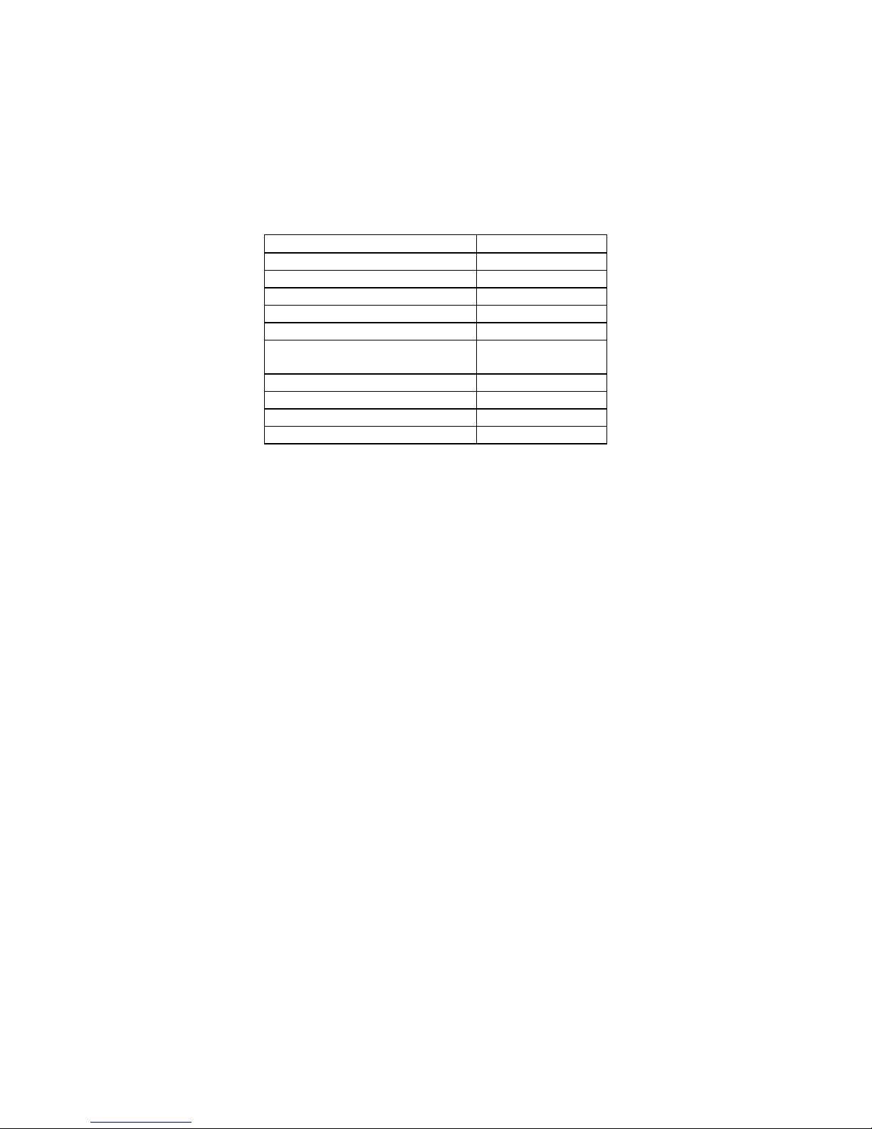
2.4.12 Special Modes
The special modes are not frequently used and they may be selected by pressing the “Select
Function” key while simultaneously pressing a combination of multiple EDIT keys. The unit
must be in the normal mode of operation to enter any of the special modes of operation. The
table below shows the combination of the EDIT keys that need to be pressed to obtain the
desired special mode.
Mode EDIT keys
1. Addressing RIGHT
2. Error List LEFT
3. Reset UP
4. Store Setup in EEPROM DOWN
5. Test Display UP & LEFT
6. Recall Default Setup DOWN &
RIGHT
7. Calibration LEFT & RIGHT
8. Troubleshooting UP & DOWN
9. Not Assigned UP & RIGHT
10. Not Assigned DOWN & LEFT
1. Addressing by RS-232
This special mode selection provides for programming the address of the unit used for
computer control through the RS-232 serial communication. The unit’s address applies to
all 3 channels (same address regardless of the channel selection).
The unit determines its address at power up by using the following algorithm:
1) VID: Address determined by ID voltage set in hardware (see table in
section 10.0)
2) MEM: Address stored in non-volatile memory
3) READ VID
4) IF VID = 0 THEN Address = MEM
5) IF VID > 0 THEN Address = VID = MEM
This special mode is selected by pressing the “Select Function” key while simultaneously
pressing the RIGHT EDIT key. The unit returns to the normal mode of operation
(Monitoring or Non-monitoring state) after pressing the “Select Function” key one more
time.
When this special mode is selected the first “Function LED” will be blinking and the serial
communication baud rate for the unit will be shown on the LED display. The baud rate can
be modified by using the EDIT keys. An additional press of the “Select Function” key will
make the second “Function LED” blink and the address of the unit will be shown on the
LED display. The address can be modified by using the EDIT keys only if VID = 0. The
new address will be set and stored into the internal non-volatile memory when the unit
returns to the normal mode of operation.
2. Error List
This special mode selection allows the user to retrieve a listing of all of the errors that may
be causing the failure LED to be ON.
This special mode is selected by pressing the “Select Function” key while simultaneously
pressing the LEFT EDIT key. The unit returns to the normal mode of operation (Monitoring
or Non-monitoring state) after pressing the “Select Function” key one more time.
IM136
Page 17
Page 19
ENDEVCO MODEL 136 DC AMPLIFIER
INSTRUCTION MANUAL
After the mode is selected, all of the “Function LEDs” will be OFF and the first error code
will be shown on the LED display. The user may scroll through the list by using the UP
and DOWN EDIT keys.
3. Reset
This special mode selection allows the user to reset the unit (equivalent to a power-up
initialization).
This special mode is selected by pressing the “Select Function” key while simultaneously
pressing the UP EDIT key. The unit returns to the normal mode of operation (Monitoring
or Non-monitoring state) immediately after initialization.
4. Store Setup in EEPROM
This special mode selection allows the user to force the unit to store all of the function
settings into non-volatile memory.
This special mode is selected by pressing the “Select Function” key while simultaneously
pressing the DOWN EDIT key. The unit returns to the normal mode of operation
(Monitoring or Non-monitoring state) immediately after writing all of the function settings
into non-volatile memory.
5. Test Display
This special mode selection allows the user to test the display board by displaying a
different pattern on the LED indicators and the LED display every time any one of the
front panel buttons is pressed.
This special mode is selected by pressing the “Select Function” key while simultaneously
pressing the UP and LEFT EDIT keys. The unit returns to the normal mode of operation
(Monitoring or Non-monitoring state) after pressing the “Select Function” key one more time.
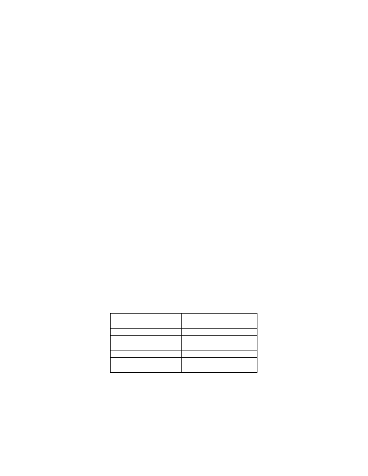
6. Recall Default Setup
This special mode selection allows the user to recall the default function settings.
This special mode is selected by pressing the “Select Function” key while simultaneously
pressing the DOWN and RIGHT EDIT keys. The unit returns to the normal mode of
operation (Monitoring or Non-monitoring state) immediately after restoring all of the
default function settings.
Function Factory Default Setting
1. Excitation Voltage 0.00 (OFF)
2. Sensor Sensitivity 1.000
3. Output Scaling 1.000
4. Low Pass Filter XX.XX (ON)
5. Auto-Zero OFF
6. Shunt Calibration OFF
7. Monitoring State Vout
7. Calibration
This special mode selection allows the user to manually calibrate the unit.
This special mode is selected by pressing the “Select Function” key while simultaneously
pressing the LEFT and RIGHT EDIT keys. When this special mode is selected the first
“Function LED” will be blinking and the first calibration constant for the selected channel
will be shown on the LED display. The settings of all of the functions will be saved in nonvolatile memory when entering this mode.
IM136
Page 18
Page 20

ENDEVCO MODEL 136 DC AMPLIFIER
INSTRUCTION MANUAL
The user selects which calibration constant is being set by subsequently pressing the
“Select Function” key. Each press of the “Select Function” key will sequentially make one
of the “Function LEDs” blink indicating that the calibration constant is selected for
programming and the corresponding calibration constant will be shown on the LED
display.
Pressing the “Select Function” push-button while the “Monitoring State” function LED is
flashing places the unit back into Normal mode. The calibration constants will be stored
into the internal non-volatile memory when the unit returns to the normal mode of
operation. The settings for all of the functions will be restored using the new calibration
constants when the unit returns to the normal mode of operation.
A checksum for the calibration constants is also stored in non-volatile memory. The unit
will use this checksum at power up to verify that all calibration constants are good. The
unit will declare an error if the checksum test for the calibration constants fails.
A cross-reference table between the calibration constants and the “Function LEDs” is
shown below (the gain setting for each calibration constant is also shown):
Function LED Calibration Constant Gain
1. Excitation Voltage k1 for 100 < Gain < 1000 200
2. Sensor Sensitivity k2 for 10 < Gain < 100 20
3. Output Scaling k3 for 0 < Gain < 10 2
4. Low Pass Filter (not defined) 2
5. Auto-Zero (not defined) 2
6. Shunt Calibration k5 to calib. slope of A/D 1
7. Monitoring State k6 to calib. offset of A/D 1
8. Gain Calibration
Calibration constants k1 through k4 are used to calibrate the gain of the unit. This is
accomplished by applying a 300 Hz calibration signal into the Isotron input for k1, k2, and
k3, or into the Charge input for k4, and adjusting the calibration constant displayed on the
LED display until the desired output (input signal multiplied by gain) is obtained. The
amplitude of the input signal should be set to 30.0 mVRMS for k1, 0.300 VRMS for k2,
3.00 VRMS for k3.
9. A/D Calibration
Calibration constants k5 and k6 are used to calibrate the Analog to Digital converter of the
unit. The unit will determine these constants at power-up. The user can view the values of
these constants by selecting Function LED #6 for k5 (slope) or Function LED #7 for k6
(offset).
10. Troubleshooting Mode
This special mode selection allows the user to control any digital I/O port for
troubleshooting purposes.
This special mode is selected by pressing the “Select Function” key while simultaneously
pressing the UP and DOWN EDIT keys. Pressing the “Select Function” push-button while
the “Monitoring State” function LED is flashing places the unit back into Normal mode.
IM136
Page 19
Page 21

ENDEVCO MODEL 136 DC AMPLIFIER
INSTRUCTION MANUAL
2.4.13 Fault Indication
There are three (3) fault indicators (red LEDs) for each channel located on the front panel.
The Fault LED will be ON if the unit was not able to successfully perform an auto-zero. The
Fault LED will be set to OFF if the Auto-Zero function is set to OFF or if an auto-zero is
successfully accomplished.
2.4.14 RS-232 Serial Communication
The unit has a standard RS-232 serial interface available through an RJ-11 connector located
on the rear panel (see figure 6).
Figure 5 shows how to connect a computer to control up to 16 136 amplifiers. The following
functions can be executed through the serial interface from a controller:
1. Identification of the unit: Model Number (133, 136, etc.), firmware revision, address.
2. Send settings for all of the 7 functions programmable through the front panel.
3. Query settings for all of the 7 functions programmable through the front panel.
4. Send calibration constants. The new calibration constant will take effect
immediately and it will be stored into non-volatile memory.
5. Query calibration constants.
6. Query raw and calibrated output RMS data from A/D.
7. Query corner frequency of installed loupes filter.
8. Query error list.
9. Reset the unit.
2.4.15 Filter Options and Installation
1. Introduction
The ENDEVCO Model 31875 plug in, Low Pass Filter Modules are optional Butterworth filters
designed for use with the Endevco Model 133, PE and ISOTRON Signal Conditioner and
Model 136, DC Amplifier. The filters are low-cost designs with sufficient corner frequencies to
accommodate most test requirements.
The self-identifying feature allows quick verification of the filter installed in a particular channel
for the model 133 or model 136. Each channel will display the filter corner frequency on the
LED digital panel meter. Only the filter corner frequency is displayed. The filter type
(Butterworth) can only be visually verified by removing the outer cover.
There are 20 corner frequencies available, ranging from 10 Hz to 80 kHz in 1, 2, 4, 6, and 8
steps for each of the three filter types. The 31875 must be specified in the following manner:
31875-XXXX-O. The "XXXX" is the -3 dB corner frequency, determined by multiplying XXXX
by 10. If the "XXXX" is left blank, the standard 10 kHz filter is supplied (-1000). The Y
indicates the filter type desired, -0 for the Butterworth if the "Y" is left blank the standard
Butterworth filter is supplied.
NOTE: The filter options of 400 Hz and 2,000 Hz are not valid frequencies. The 400 Hz filter
has been replaced by 300 Hz. The 2,000 Hz option has been replaced by 1,650 Hz. These
two lower frequency options are specifically made to comply with the filter corner
requirements of J211 and ISO6487.
If no filter is specified at time of order entry, the standard default filter installed is a 10 kHz low
pass Butterworth.
See Appendix 1 for the Model 31875 Low Pass filter data sheet and corner frequency
selections.
IM136
Page 20
Page 22
ENDEVCO MODEL 136 DC AMPLIFIER
INSTRUCTION MANUAL
2. Filter Change/Replacement
Place the model 136 on a level, firmly supported surface. Remove the two front panel
screws. Leave the front panel connector connected to the main board. Carefully slide the
black cover from the unit.
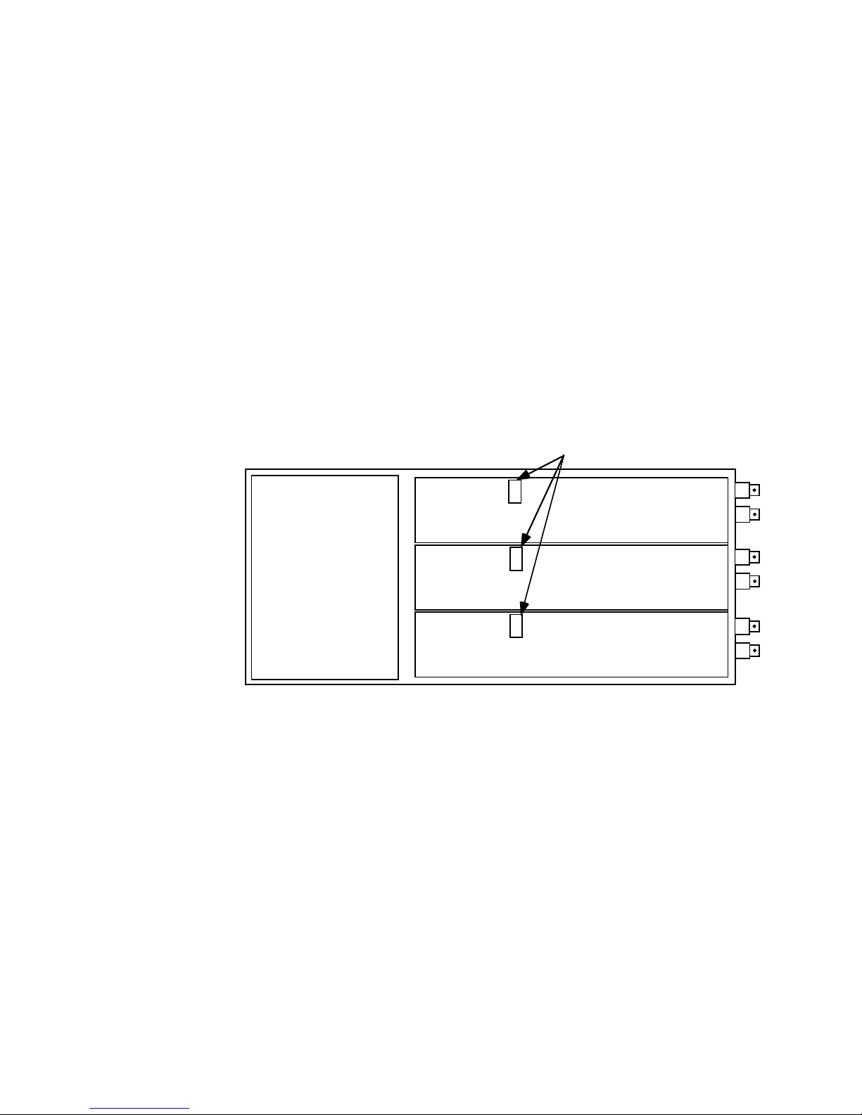
Reference Figure 8 for the location of the three filter modules. Carefully pry off the metal
grounding shield and locate the existing filter module(s) and gently pry it off (as you would an
IC in a socket) and store it for future use.
Observing the correct orientation of the new filter module(s), install it in the correct channel
location desired. Reinstall the grounding shield.
Ensure the front panel connector is firmly connected and re-assemble the cover and front
panel.
CAUTION: Ensure that the two front panel mounting screws are not over tightened or cross
threaded. The aluminum rail screws mount into soft metal that can easily be
damaged. Should the rail become damaged, simply locate a replacement
screw of a 1/2 inch longer length and install into the damaged rail. (The screws
are 4-40, stainless steel, self-tapping.)
Filter Modules
Channel 1
Unit Front
Power Supply
Channel 2
Channel 3
Figure 10
2.4.16 Sample Set Up
The following information is intended for the first time or infrequent user of this amplifier.
A. Using figure 1 as a reference, perform the following initial setups:
1. Using the "Select Channel" button, select channel 1. (The LED illuminated is the channel
that is being monitored by the DPM.)
2. Using the "Select Function" button, select the appropriate voltage level for the sensor type
used. While the LED is flashing for the Input Select function, press the "Edit" button
directly above or below the word "Edit" on the front panel. This will cause the DPM to
display either 0, 5, 10 or 15 VDC. Once the appropriate voltage is selected, press the
"Select Function" button to save the voltage level and the "Select Function" LED will
automatically advance to the next function.
3. Press the "Select Function" button to advance to "Sensitivity (mV/EU)". While the LED is
flashing, enter the correct sensitivity value of the sensor being used. (This is
IM136
Page 21
Page 23

ENDEVCO MODEL 136 DC AMPLIFIER
INSTRUCTION MANUAL
accomplished with the top and bottom "Edit" buttons to increase or decrease the value.
The left and right "Edit" buttons move the significant digit on the DPM to be changed. The
actual value must be within the range of 0.001 to 9999.)
4. Press the "Select Function" button to advance to "Output Scaling (mV/EU)". While the
LED is flashing, enter in an appropriate value, which must be within the following limits:
(The scaling value entered is valid for 0.001 to 9999 along with the following limitation: 0 •
Output Scaling / Sensor sensitivity • 1000.
To better understand the correct scaling value to enter, the following questions must be
answered:
a. What is the desired full scale output voltage?
b. What is the maximum g range to be measured (in g's or EU)?
c. What is the sensor sensitivity?
Example 1.
The desired full scale output voltage is 1.0 volt; The desired full scale input range is 2 g's;
The sensor sensitivity is entered is 10.04 mV/g. The value to enter for output scaling is:
500.
Therefore, when the output is 1 volt, the input to the unit is equivalent to 2 g's.
Example 2.
The desired full scale output voltage is 10.0 volts; The desired full scale input range is 5
g's; The sensor sensitivity is entered as 0.95 mV/g. The correct scaling factor is: 2000.
The output is equivalent to 2 volts per g. At full scale of 10 volts the output is 5 g's.
5. Press the "Select Function" button to advance to "LP Filter (kHz)". The options are OFF
or 10.00 for the standard default 10 kHz filter module.
6. Press the "Select Function" button to advance to "Auto-Zero". The options are ON, OFF
or AUTO. Each mode is defined as follows: OFF - all offset adjustments are set to
neutral; ON - This sets the DC output voltage to zero within ± 10 mVDC; AUTO - This
mode executes an automatic zero of the DC output Voltage whenever one of the following
function are changed: Excitation Voltage, Sensor Sensitivity, Output Scaling and
changing of the Low Pass Filter Mode.
7. Press the "Select Function" button to advance to "Shunt Calibration". The choices are:
"OFF, RSH or RSH-". Each mode is defined as follows: "OFF" - the shunt calibration
resistor is disconnected from the sensor. "RSH" - the shunt calibration resistor is
connected to the PSEN+ line. "RSH-" - the shunt calibration resistor is connected to the
PSEN- line.
8. Press the "Select Function" button to advance to "Monitoring State". The options are EU,
V out or OFF. (Assume V out, which monitors the vibration from the accelerometer and
displays the RMS voltage on the DPM.)
9. Connect the PR accelerometer cable to the input connector of channel 1, on the rear of the
Model 136. Attach the accelerometer to a known vibration source, such as a shaker, as a
means to verify the input vibration level and verify the output with various input g levels.
10. Connect an oscilloscope, or other monitoring devices to visually see the input signal, or
reference the DPM on the front of the Model 136.
11. Channels two and three are controlled in a similar manner.
IM136
Page 22
Page 24

ENDEVCO MODEL 136 DC AMPLIFIER
INSTRUCTION MANUAL
2.5 RACK MOUNTING KIT
A. Description
The optional rack mounting kit, PN 31979, is an optional kit that can be purchased to mount
from one to three of the Model 133/136 units (the Model 133 is a three-channel
PE/ISOTRON® using the same package as the Model 136). The kit consists of the two blank
panels, the front panel mount and the support bracket. The kit is designed to mount to
standard 19" rack enclosures.
B. Mounting Instructions
To install one or more model 133/136 units, first remove the two front panel screws from the
Model 136. Gently remove the plastic frame from the Model 136 front panel (store the panel
for future use and for return of the unit to Endevco when required). Hold the Model 136
behind the front panel mount, (the part with three cut-out rectangular holes), gently insert the
Model 136's front panel through the correct position to be mounted. Reinstall the Model 136’s
using the longer 3/4” front panel screws provided in the 31979 Rack Mount Kit, sandwich
between the Model 136’s front panel and the Model 136’s main body.
install the other units. The blank panels are used only when one or two Model 136's are used.
In a similar manner,
IM136
Page 23
Page 25

ENDEVCO MODEL 136 DC AMPLIFIER
INSTRUCTION MANUAL
Section 3: ROUTINE MAINTENANCE AND HANDLING
3.1 INTRODUCTION
The Model 136 DC Amplifier is self-contained electronic instrument that requires minimal
maintenance.
The Model 136 is designed to require no component-level repair by the user. However,
detailed schematics are available upon request.
The only periodic function performed by the user is quality calibration. Any component
failures simply require the user to return the unit to Endevco for repair/replacement.
Should a faulty unit be returned to Endevco, it is suggested that the original or equivalent
packaging be used. This will reduce damage to the equipment during shipment.
3.2 FACTORY SERVICE
A. FACTORY SERVICE
Endevco maintains factory service repair for all Endevco instruments. To obtain repair or
replacement of a defective instrument, place a call to Endevco to obtain a return material
authorization number (RMA), then return the instrument to the factory at the following
address:
Endevco
30700 Rancho Viejo Road
San Juan Capistrano, CA 92675
949-493-8181
To return an instrument, please:
1. Ensure proper packaging, preferably the original shipping cartons.
2. Prepay shipping and insurance charges.
3. Attach the Return Material Authorization (RMA) number from Endevco and include any
information that may be pertinent to the description of the failure/problem.
B. WARRANTY
Endevco warrants each new electronic instrument to be free from defects in material and
workmanship. Please refer to the appropriate Warranty Policies for the terms and warranty
period. Instruments returned under warranty will be repaired or replaced at no charge, If the
failure is due to defective material or workmanship; and the unit is returned within the time
period and conditions of Endevco's warranty policy.
C. OUT-OF-WARRANTY RETURNS
Enclose a purchase order not to exceed $300.00, authorizing repair/calibration along with a
full explanation of the failure or symptoms observed to help in fixing the problem. The
instrument will be repaired/calibrated, returned and invoiced for the actual repair charges. If
the instrument cannot be repaired for $300.00 or less, Endevco will submit a written quotation
for the cost of the repair and/or replacement of the unit.
IM136
Page 24
Page 26

ENDEVCO MODEL 136 DC AMPLIFIER
INSTRUCTION MANUAL
3.3 Ordering Information and Accessories
ENDEVCO® Model 136 must be specified in the following manner: 136-X
If no filter is specified at time of order entry, the standard default filter installed is a 10 kHz low
pass Butterworth.
If X is left blank, the standard 90-240 VAC Power is supplied. If X = 1, then the 9-18 VDC
Power is supplied.
Description Endevco Part No. Quantity
Supplied
Instruction Manual IM136 1
EC320 AC Power Cord EW599 1
Resistor Header for 4-pole Low Pass Filter 31875-XXXX-O 0
Serial DB9F to RJ-11 Adapter EJ807 0
7 ft. 6P4C Cable with RJ-11 Modular Plugs, Straight
Pinning
12 VDC Power Supply, 26 Watts EHM1413 0
Auto Lighter to 760 Plug Cord Assembly (136-1 only) EHM1409 1
9-pin “D” Mating Connector Kit 29719-2 0
Rack Mount Kit 31979 0
Application Software 35933 0
Inline Coupler, RJ11 (6 x 4) EJ847 0
Cable, 6P4C, Straight, w/RJ11 (2 ft.) EW1077 0
Modular Splitter Adapter M-F (6 x 4) EJ822 0
EW1027 0
IM136
Page 25
Page 27

SECTION 4:
ENDEVCO MODEL 136 DC AMPLIFIER
INSTRUCTION MANUAL
SECTION 4:
APPENDIX 1 FILTER MODULE MODEL 31875 DATA SHEET
APPENDIX 1 FILTER MODULE MODEL 31875 DATA SHEET
The choices of Butterworth filter corner frequencies are as follows:
fo (Hz) Part number to
order
10 31875-0001-0
20 31875-0002-0
40 31875-0004-0
60 31875-0006-0
80 31875-0008-0
100 31875-0010-0
200 31875-0020-0
300 31875-0030-0
600 31875-0060-0
800 31875-0080-0
1000 31875-0100-0
1650 31875-0165-0
4000 31875-0400-0
6000 31875-0600-0
8000 31875-0800-0
10,000 31875-1000-0
20,000 31875-2000-0
40,000 31875-4000-0
60,000 31875-6000-0
80,000 31875-8000-0
IM136
Page 26
Page 28

ENDEVCO MODEL 136 DC AMPLIFIER
INSTRUCTION MANUAL
APPENDIX 2 SERIAL COMMUNICATION
Communication Protocol - Each transmission is of the form: [Header] [;] [Body]
The Header and Body are separated by a semi-colon and are each made up of several components
separated by one space. Square brackets, [], indicate a mandatory component. Curly brackets,{},
indicate a conditional component. The Header is of the form;
[Model/Unit] [space] [Channel] [space] [Command]
The Body is of the form;
{data} [checksum] [Terminator]
Each transmission to a 13x unit will invoke a response of this same form.
Each component of the transmission is decimal integer ASCII text.
Model/Unit (Required) is a two byte value in which the upper byte indicates the model type (0=133,
1=136) and the lower byte indicates a Unit number in the range 1-20. However, commands 0,6 & 8
allow 0 to indicate the command and it’s associated data, if any, applies to the specified channel of all
units with the identified Model Type.
In Rack mount systems the Unit address of each 3 channel device is determined by the rack. For
standalone systems the address is programmable through the front panel. All units will receive all
serial transmissions. However, only the unit with the same unit address will respond.
Channel (Required) is in the range 1-3. However, commands 0,2,3,4,5 & 7 allow 0 to indicate the
command and it’s associated data, if any, applies to all channels.
Command: (Required) is one of the following:
0x00 - [Channel x ] {Setup data} {checksum} follows - (13x Receives)
0x01 - [Channel x ] {Cal Constant Data}{checksum} follows - (13x Receives)
0x02 - [Channel x ] Send {Setup/Status data} - (13x Sends)
0x03 - [Channel x ] Send {Calibration Constant Data} - (13x Sends)
0x04 - [Channel x ] Send data - (13x Sends)
0x05 - [Channel x ] Send Raw data - (13x Sends)
0x06 - [Channel x ] Stop Sending data (unit # = 0 indicates all units are to stop)
0x07 - [Channel x ] {Data Interval in seconds (0=single shot)}
0x08 - Reset Unit (unit # = 0 indicates all units of this model type are to reset)
0x09 - Send Unit ID (13x Sends)
0x0A - Send LP Corners (13x Sends for all channels)
0x0B - Send Error List (13x Sends for all channels)
Data: The Setup Data, Cal Constant Data and Data Interval - commands (0,1&7) require additional
information to accompany the command. The format of these data packets is as follows;
Channel Setup Data - This packet consists of 7 items. These items correspond exactly to the 7 items
associated with the Programming Mode Function LEDs on the front panel of the 13x units. If the unit
number indicated in the transmission header equals zero (0) then data will be applied to all units for the
specified channel(s). If the channel number indicated in the transmission header equals zero (0) then data
will be applied to all three channels of the addressed unit. The following must be adhered to for proper
reception by the 13x units:
IM136
Page 27
Page 29

ENDEVCO MODEL 136 DC AMPLIFIER
INSTRUCTION MANUAL
1) The order of these items is fixed. For Model 133 the order is Input Select to Monitoring, for
Model 136 the order is Voltage Excitation to Monitoring. For the range of possible settings for
each item see the sections below on model specific hardware control.
2) Only complete setups are accepted (all 7 items sent even if only 1 changes).
3) Each item’s setting must be converted to a decimal integer string scaled to accommodate the
transmission of floating point values with resolutions to 1/1000. (ie all item settings are multiplied
by 1000 and converted to ASCII).
4) Each item is separated by 1 space character (0x20)
Channel Calibration Constant Data - This packet consists of 7 items. These items correspond exactly to
the 7 items associated with the Function LEDs on the front panel of the 13x units while in Calibration
Mode. The specifics of these are detailed in the section specifying Calibration Mode. Their method of
transmission is identical to that of the channel setup transmission.
Data Interval - This is an unsigned integer value (16 bits) which represents the number of seconds
between data transmissions, calibrated or raw, after either of the ‘Send Data’ commands is sent to a 13x
unit. A value of 0 indicates a single sample of data is requested. The 13x firmware will terminate the Send
Data condition after 1 sample of data (per enabled channel) is sent. To accomplish single transmissions
easily set the Data Interval to 0 first then send Send Data commands at will. One data sample per Send
Data command will be returned with this scenario. The firmware default is 0 - Single Shot mode.
Checksum (Required) A one byte summation of the entire transmission, header and data (if any) without
the terminator, is required on all transmissions sent to the 13x.
Terminator (Required) The last item in the transmission, A Line Feed character (0x0A).
Response (Required) The following table illustrates the response to the received command and the error
responses;
Command # Command 13x Response
0x00 Setup to 13x ACK
0x01 Cal Constants to 13x ACK
0x02 Setup from 13x Cmd <data>
0x03 Cal Constants from 13x Cmd <data>
0x04 Calibrated Vout data ACK ....Cmd <data>
0x05 Raw Vout data ACK ....Cmd <data>
0x06 Stop Data ACK
0x07 Data Interval to 13x ACK
0x08 Reset Unit ACK
0x09 Unit ID from 13x Cmd <data>
0x0A LP Corners from 13x Cmd <data>
0x0B Error List from 13x Cmd <data>
0x0C ACK
0x0D Bad CS or Not enough data NAK
0x0E Channel # too high Bad Channel
0x0F Setup value out of range Bad Setup
0x10 Hw setup unit reports error Setup Error
0x11 Setup value out of range Bad Cal Constant
Reason 13x Error Responses
IM136
Page 28
Page 30

ENDEVCO MODEL 136 DC AMPLIFIER
INSTRUCTION MANUAL
Response Data (conditional): The following sections describe the response of the 13x to commands that
require it to send data (all data described below follows a transmission Header identical to that described
above).
Channel Setup Data - The data sent in response to the ‘Setup from 13x’ command (0x02) is identical to
the format of the Setup to 13x’ command (0x00) described above. If the channel number indicated in the
header equals zero (0) then data will be sent for all three channels.
Calibration Constant Data - The data sent in response to the ‘Cal Constants from 13x’ command (0x03) is
identical to the format of the Cal Constants to 13x’ command (0x01) described above. If the channel
number indicated in the header equals zero (0) then data will be sent for all three channels.
Calibrated Vout Data - The data sent in response to the ‘Calibrated Vout Data ‘ command (0x04) will be for
the channel indicated in the transmission header. If the channel number equals zero (0) then data will be
sent for all three channels. The transmission of data for the indicated channel(s) will continue at the rate
specified by the ‘Data Interval to 13x’ command. The data will be one or three values formatted to be a
decimal integer string. To render it back to a floating point number it should first be converted from a string
to an integer and then divided by 1000.
NOTE: If the unit is not in the ‘Normal’ mode of operation at the time it is scheduled to output data
remotely, that data transmission will be skipped.
Raw Vout Data - The format of the data sent in response to the ‘Raw Vout Data ‘ command (0x05) is
identical to the Calibrated Vout Data discussed above.
Unit ID Data - The data sent in response to the ‘Unit ID from 13x ‘ command (0x09) is a string which states
the Model number and the firmware revision (i.e 133 REV A).
LP Corners Data - This data, sent in response to the ‘LP Corners from 13x‘, command (0x0A) is a three
item packet in the Decimal Integer String format which represents the Low Pass Filter corner frequency (in
kHz) for each channel. To convert this integer to a floating point number divide by 100. (The internal 13x
representation of this data is a 4 character string with an implied decimal point after the 2nd MS digit. This
is why the division is by 100 and not 1000 used elsewhere).
Channel Error Data - This data, sent in response to the ‘Error List from 13x‘, command (0x0B) is a three
item packet in the Decimal Integer String format which represents the 13x errors on a per channel basis.
This data should be converted from the string format to an integer format (no division). the three items are
bit maps representing errors for each channel. The bit maps for each model are as follows:
Model 133
Bit 0 = 1 = EEPROM Write Error
Bit 1 = 1 = EEPROM Channel Setup Read Error
Bit 2 = 1 = EEPROM Calibration Constant Read Error
Bit 3 = 1 = Function Error
Bit 4 = 1 = Input Select Error
Model 136
Bit 0 = 1 = EEPROM Write Error
Bit 1 = 1 = EEPROM Channel Setup Read Error
Bit 2 = 1 = EEPROM Calibration Constant Read Error
Bit 3 = 1 = Function Error
Bit 4 = 1 = Auto Zero Error
Transmission Error Responses - In the event of a transmission error or data packet parameter errors one
of the following may be sent by the 13x unit.
IM136
Page 29
Page 31

ENDEVCO MODEL 136 DC AMPLIFIER
INSTRUCTION MANUAL
NAK (0x0C) - This response indicates either a bad checksum was calculated or there was not enough
data transfered to satisify the command requirements (i.e. a setup command with less that 7 items).
Bad Channel (0x0D) - This response indicates a channel number greater than 3 was received.
4.2.7.4.8.8.3 Bad Setup (0x0E) - This response indicates a Setup parameter received was out of
range.
Setup Error (0x0F) - This response indicates that when a setup was implemented it resulted in an error.
Bad Calibration Constant (0x10) - This response indicates that a calibration constant received was out of
range.
Serial Port Communication Parameters - Each unit has two parameters, Baud Rate and Address. These
parameters are accessible from the Serial Mode which is entered by holding down the right arrow key and
pressing the Function Select key (see the section on Other Modes).
Model 136 Serial Port Communication Example
ASCII String to send the Receive Unit ID command to a hypothetical Model 136, unit =20, Channel 1,
command 9 - Receive Unit ID)
276\s1\s9;132
Where;
1. ASCII ‘276’ (50,55,54) is the result of the binary operation ((1 << 8) | 20). Where 1=Model 136
and 20 is the unit number (this binary number is then converted to an ASCII string).
2. ‘\s’ is a space (ASCII 32decimal)
3. ASCII ‘1’ (49) is the binary channel # 1 converted to ASCII.
4. ‘\s’ is a space (ASCII 32decimal)
5. ASCII ‘9’ (57) is the binary command # 9 (Receive Unit ID) converted to ASCII.
6. ‘;’ (ASCII 59decimal) is a header separator
7. ASCII ‘132’ is the checksum of the command string. It is an ASCII representation of a binary
summation of bytes. A checksum is required for all data sent to the unit. It is calculated as
follows;
checksum calculation = 50+55+54+32+49+32+57+59=388=184hex checksum = lower byte
only 84hex=132decimal
ASCII String to send the following configuration data to a hypothetical Model 136, unit =1, Channel ALL
(0), Command =0 - Send Setup);
Voltage Excitation = 5.0 = 3 (selected from the enumerated type def {0.0,15.0,10.0,5.0})
Sensitivity=2.123 (floating Point value )
Output Scaling =3.456 (floating Point value )
Low Pass Filter = 10.0 = 1 (selected from the enumerated type def {OFF,10.0})
Auto Zero = AUTO = 2 (selected from the enumerated type def {OFF,ON,AUTO})
Shunt Calibration = RSH- = 1 (selected from the enumerated type def {OFF,RSH-,RSH+ })
Monitoring Option = VOUT = 1 (selected from the enumerated type def {OFF,VOUT,EU})
IM136
Page 30
Page 32

ENDEVCO MODEL 136 DC AMPLIFIER
INSTRUCTION MANUAL
ASCII Representation of string;
257\s0\s0;3000\s2123\s3456\s1000\s2000\s1000\s1000\s187
Binary Representation of ASCII string (these are the bytes actually transmitted via rs-232 in
decimal);
50,53,55, 32,48,32,48,59,51,48,48,48,32,50,49,50,51,32,51,52,53,54,32,49,48,48,48,32,
50,48,48,48,32,49,48,48,48,32,49,48,48,48,32,49,53,56,55
Where;
1. ASCII ‘257’ (50,53,55) is the result of the binary operation ((1 << 8) | 1). Where 0=Model 136
and 1 is the unit number (this binary number is then converted to an ASCII string).
2. ‘\s’ is a space (ASCII 32decimal)
3. ASCII ‘0’ (48) is the binary channel # 0 (all channels) converted to ASCII.
4. ‘\s’ is a space (ASCII 32decimal)
5. ASCII ‘0’ (48) is the binary command # 0 (Send Setup) converted to ASCII.
6. ‘;’ (ASCII 59decimal) is a header separator.
7. ASCII ‘3000’ (51,48,48,48) is the Voltage Excitation option 3 (5.0) multiplied by 1000. This
multiplication is done to normalize all of the data. Some values are floating point others are
integer. All items in the setup are multiplied by 1000 to scale the floats to a fixed point number
with the desired resolution.
8. The next 6 items are processed the same as the input select item.
9. ASCII ‘187’ is an ASCII representation of a binary summation of bytes. A checksum is
required for all data sent to the unit. It is calculated as shown above.
10. The response to the string will be an ACK (0x0C)
IM136
Page 31
 Loading...