

ENDEVCO 4830B Instruction Manual

®
4830B
AccelerometerSimulat
IM4830B
Instruction manual
or
IM4830B Rev B
October 9, 2019

SAFETY CONSIDERATIONS
This equipment has been designed and tested in accordance with the following standards:
EN61326-1:2006 Electrical equipment for measurement, control and laboratory use – Group1, Class A
(Emissions)
EN61326-1:2006 Electrical equipment for measurement, control and laboratory use – Industrial Location
Immunity
EN61000-3-2:2006 Electromagnetic compatibility (EMC) – Part 3-2
(+A1/A2)
EN61000-3-3:2008 Electromagnetic compatibility (EMC) – Part 3-3
CFR 47, Class A Code of Federal Regulations: Pt 15, Subpart B
The 4830B has been tested as an Unintentional radiator (sub part B) and as a Class A product
RADIO AND TELEVISION INTERFERENCE
NOTE: This equipment has been tested and found to comply with the limits for a Class A digital device, pursuant to Part 15 of the
FCC rules. These limits are designed to provide reasonable protection against harmful interference when the equipment is
operated in a commercial environment. This equipment generates, uses and can radiate radio frequency energy and, if not
installed and used in accordance with the instruction manual, may cause harmful interference to radio communications.
Operation of this equipment in a residential area is likely to cause harmful interference in which case the user will be required to
correct the interference at his own expense.
In order to maintain compliance with FCC regulations shielded cables must be used with this equipment.
Operation with non-approved equipment or unshielded cables is likely to result in interference to radio & television reception.
This equipment is not designed to be used in potentially explosive environments. It should not be used in the presence of
flammable liquids or gases.
This manual contains information and warnings that must be followed to ensure safety of personnel and the safe operation of the
equipment.
Warnings:
Switch off all power to equipment before connecting or disconnecting the digital interface. Failure to do so may cause damage to
the equipment.
Any adjustment, maintenance or repair, other than detailed within this manual, must be carried out by trained service personnel.
If it is suspected that the correct operation of the equipment is threatened, impaired or otherwise, it must be made safe and free
from further operation until the threat has been removed.
Rohs Compliant 2011/65/EU
Waste Electronic and Electronic Equipment Directive: 2012/19/EU
This product complies with the WEEE Directive (2012/19/EU) marking requirement. The affixed product label (below) indicates that
you must not dispose this electrical/electronic product in domestic household waste.
To return unwanted product for disposal, please contact your local MSS representative.
IM4830B Rev B 2
October 9, 2019

Warranty and software license agreement
4830B Simulator Utility License
Except where otherwise noted, all of the documentation and software included in the Simulator Utility Setup package is
copyrighted by KDP Electronic Systems Ltd.
Copyright (C) 2000-2014 KDP Electronic Systems Ltd. All rights reserved.
This software is provided "as-is," without any express or implied warranty. In no event shall the author(s) be held liable
for any damages arising from the use of this software.
Permission is granted to anyone to use this software commercially for the purpose of programming the device known as
4830B Simulator and to alter and redistribute it, provided that the following conditions are met:
1. The origin of this software must not be misrepresented; you must not claim that you wrote the original software. If you
use this software to distribute a product, an acknowledgment in the product documentation would be appreciated but is
not required.
2. Modified versions in source or binary form must be plainly marked as such, and must not be misrepresented as being
the original software.
TERM OF LICENSE
This LICENSE shall continue for as long as the USER uses the SOFTWARE and/or distributes the SOFTWARE according to
the terms of this agreement. However, this LICENSE will terminate if the USER fails to comply with any of its terms or
conditions. The limitations of warranties and liability set forth in this LICENSE shall continue in force even after
termination.
ACCEPTANCE OF THIS LICENSE AGREEMENT
By downloading and/or installing this SOFTWARE, the USER agrees to the terms of this LICENSE.
DISCLAIMER OF WARRANTY AND LIABILITY
THE SOFTWARE AND THE ACCOMPANYING FILES ARE PROVIDED "AS IS" WITHOUT WARRANTY OF ANY KIND. TO THE
MAXIMUM EXTENT PERMITTED BY APPLICABLE LAW, KDP DISCLAIMS ALL WARRANTIES, EXPRESSED OR IMPLIED,
INCLUDING, BUT NOT LIMITED TO, ANY IMPLIED WARRANTIES OF PERFORMANCE, MERCHANTABILITY, FITNESS FOR A
PARTICULAR PURPOSE, AND NONINFRINGEMENT. TO THE MAXIMUM EXTENT PERMITTED BY APPLICABLE LAW, IN NO
EVENT SHALL KDP BE LIABLE FOR ANY DIRECT, INDIRECT, CONSEQUENTIAL OR INCIDENTAL DAMAGES (INCLUDING,
BUT NOT LIMITED TO, DAMAGES FOR LOSS OF BUSINESS PROFITS, BUSINESS INTERRUPTION OR LOSS OF BUSINESS
INFORMATION) ARISING OUT OF THE USE OF OR INABILITY TO USE THE SOFTWARE.
IM4830B Rev B 3
October 9, 2019

Table of Contents
1.0 Product description ........................................................................................................................................................ 6
2.0 User interface ................................................................................................................................................................. 7
3.0 Basic operation ............................................................................................................................................................... 8
3.1. Menu structure ........................................................................................................................................................... 8
3.2. Home screen ............................................................................................................................................................... 8
3.3. Editing screen ............................................................................................................................................................. 9
3.4. The “Profile” ............................................................................................................................................................... 9
3.4.1. Default profile ....................................................................................................................................................... 10
3.4.2. User profile ........................................................................................................................................................... 10
3.4.3. Profile selection .................................................................................................................................................... 10
3.5. Tools .......................................................................................................................................................................... 10
3.5.1. FFT ........................................................................................................................................................................ 10
3.5.2. Configuration ........................................................................................................................................................ 11
3.5.3. Output socket select ............................................................................................................................................. 11
3.5.4. Download data ...................................................................................................................................................... 11
3.5.5. About ..................................................................................................................................................................... 11
3.6. Power ........................................................................................................................................................................ 12
3.6.1. Low battery indicator ............................................................................................................................................ 12
3.6.2. Battery charge indicator ....................................................................................................................................... 12
3.7. Output types and typical connection configurations ................................................................................................ 12
4.0 Detailed operation ........................................................................................................................................................ 14
4.1. Parameter editing ..................................................................................................................................................... 14
4.2. Calculated parameters ............................................................................................................................................. 14
4.2.1. Relationships ........................................................................................................................................................ 14
4.2.2. Back calculation ................................................................................................................................................... 14
4.2.3. Display Format ..................................................................................................................................................... 15
4.3. Creating and saving a user profile ........................................................................................................................... 15
4.4. Accessing stored user profiles ................................................................................................................................. 16
4.5. Clearing user profiles ............................................................................................................................................... 16
4.6. Tachometer output ................................................................................................................................................... 16
IM4830B Rev B 4
October 9, 2019

4.7. FFT ............................................................................................................................................................................ 17
4.8. Setting the clock ....................................................................................................................................................... 17
4.9. Backlight operation .................................................................................................................................................. 19
4.10. Setting the display contrast ...................................................................................................................................... 19
4.11. Output socket select ................................................................................................................................................. 20
4.12. Master reset .............................................................................................................................................................. 20
4.13. Battery charging ....................................................................................................................................................... 20
5.0 Calibration, maintenance and repair ........................................................................................................................... 22
5.1. Calibration ................................................................................................................................................................ 22
5.1.1. Equipment requirements ..................................................................................................................................... 22
5.1.2. Preliminary instructions ....................................................................................................................................... 22
5.1.3. Procedure ............................................................................................................................................................. 22
5.2. Maintenance ............................................................................................................................................................. 23
5.3. Repair ........................................................................................................................................................................ 24
6.0 Utility software .............................................................................................................................................................. 24
6.1. Introduction ............................................................................................................................................................... 24
6.2. Installing the utility software .................................................................................................................................... 24
6.3. Opening and running the utility ................................................................................................................................ 25
6.3.1. Creating and saving profiles / profile sets ........................................................................................................... 26
6.3.2. Editing a profile ..................................................................................................................................................... 27
6.3.3. Opening a profile set ............................................................................................................................................. 29
6.3.4. Saving a profile set ............................................................................................................................................... 29
6.3.5. Adding a profile ..................................................................................................................................................... 29
6.3.6. Delete last profile ................................................................................................................................................. 29
6.3.7. Communicating with the simulator ...................................................................................................................... 29
7.0 Accessories ................................................................................................................................................................... 31
8.0 FAQ (Frequently Asked Questions) ............................................................................................................................... 32
IM4830B Rev B 5
October 9, 2019

1.0 Product description
The 4830B accelerometer simulator is a hand held battery operated signal generator designed specifically to
simulate the electrical output of common types of accelerometers. The instrument contains a highly accurate
oscillator with an adjustable output level and is ideal for setting up, testing and the diagnosis of faults within data
acquisition systems, FFT analyzers, environmental test systems or simply as a flexible signal generator.
The instrument provides AC output signals which mimic those of either voltage mode accelerometers (generic
IEPE, Isotron® types etc.) or charge mode accelerometers (both single ended and differential configurations).
The simulation outputs are conveniently scaled in units of acceleration, i.e. “g”, as mV/g (millivolt) or pC/g (picocoulomb) signals as appropriate, although the outputs can be configured to be proportional to units of velocity or
displacement. An auto-calculating on screen “Vibration Calculator” provides the user with corresponding values
in respect of m/s², ips, mils, mm and m/s based units.
The instrument also features a TTL compatible tachometer output which allows operators of condition monitoring
systems to set signal conditioning tracking filter center frequencies without the need to generate an external,
real time tachometer signal. The tachometer frequency is adjustable as a ratio of the respective output signal
frequency.
The 4830B also features the ability to analyze a vibration signal using a Fast Fourier Transfer function. This
allows a voltage proportional vibration signal to be inputted to the instrument thereby providing an indication of
both frequency and magnitude.
Simulation parameters can be selected, adjusted, and saved as a “profile” either by the front panel keypad or
using the supplied utility program. Use of the utility program not only allows profiles to be created and saved but
also organized into specific “profile sets” which can be conveniently stored on a PC. Up to 40 user profiles may be
downloaded to the simulator at any one time.
IM4830B Rev B 6
October 9, 2019

2.0 User interface
Figure 1: 4830B user interface
IM4830B Rev B 7
October 9, 2019
3.0 Basic operation
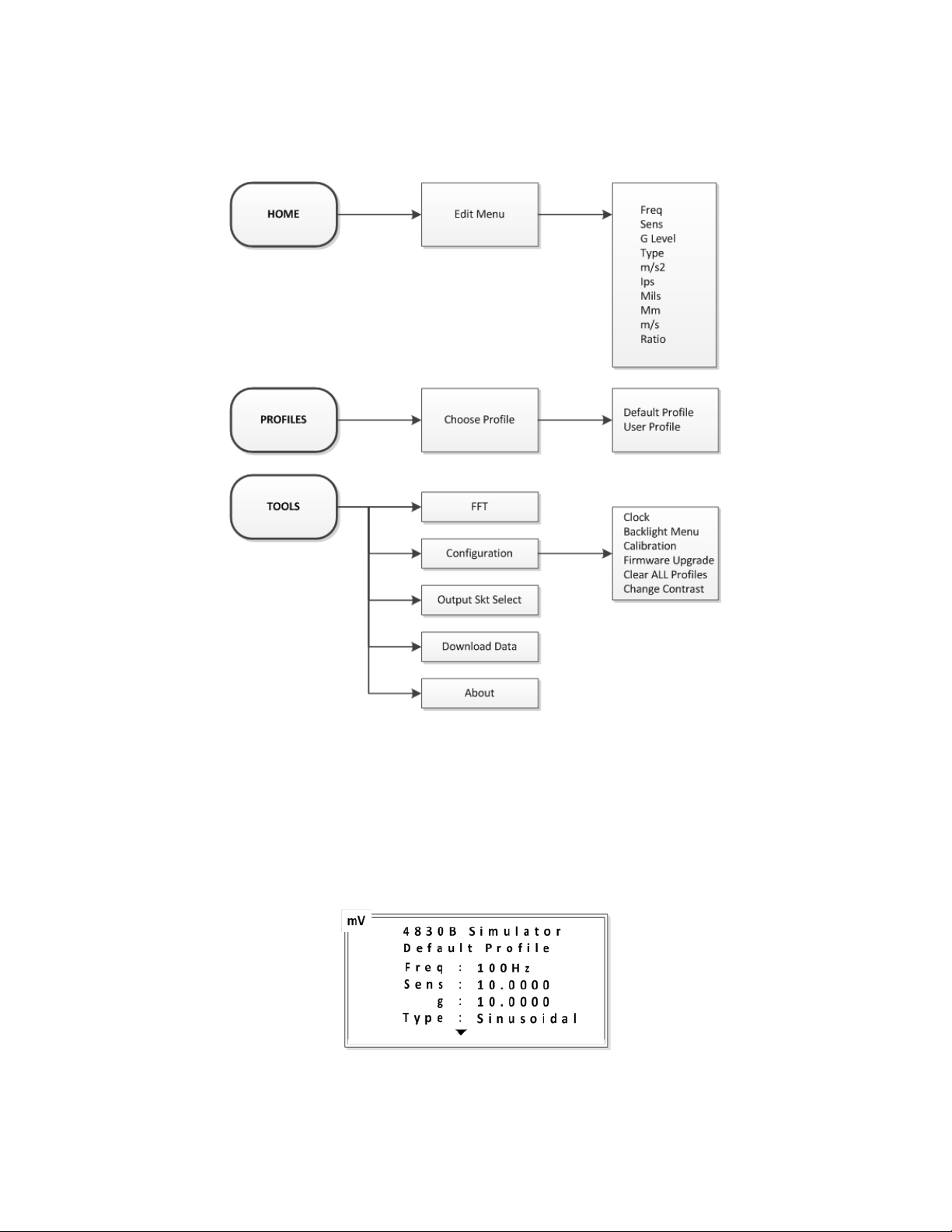
3.1. Menu structure
The simulatormenusare accessed via the three menu keys as shown in Figure 2below.
Figure 2: Menu structure
3.2. Home screen
The home screen is in two parts, upper and lower. When the simulator is turned on, the upper screen
becomes the default. This screen shows the “Profile” in use and an overview of the four primary simulation
parameters. The secondary parameters are shown in the lower screen. Moving between the upper and
lower screens is accomplished by pressing the up and down arrow keys. Pressing the
any point will return the display to the home screen.
Figure 3: Home screen, upper
IM4830B Rev B 8
October 9, 2019
HOME
menu key at
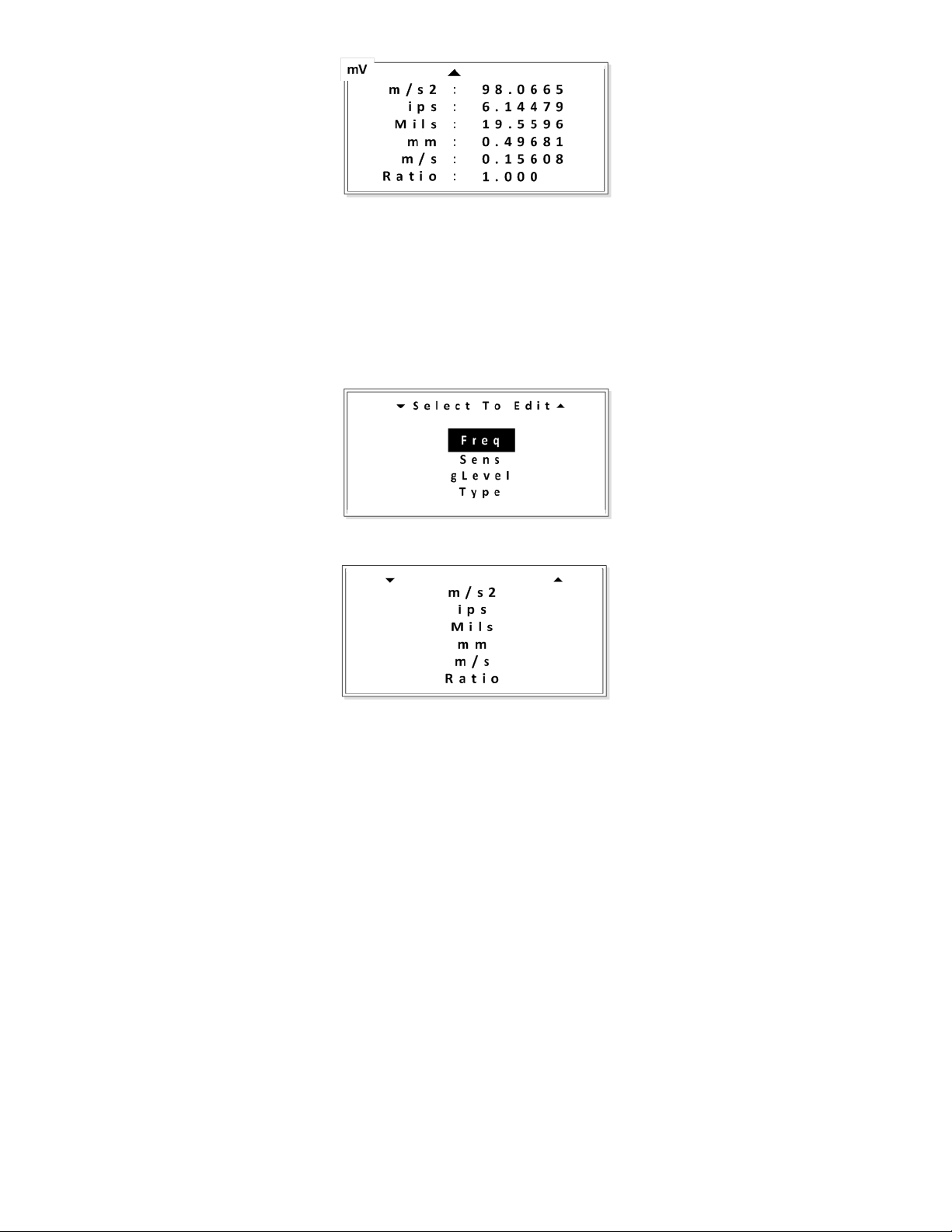
3.3. Editing screen
The editing screenis accessed by pressing either the left or right arrow keys when in the home screen.
Similar to the home screen, the editing screens are in two parts, i.e. primary and secondary parameters.
Scroll up or down with the arrow keys to move between parameters and the upper and lower screens.
Move the cursor (inverted text) to the parameter that is to be edited, and select by pressing the
See section4.1for details on editing a parameter.
Figure 4: Home screen, lower
Figure 5: Edit screen, upper
ENTER
key.
Figure 6: Edit screen, lower
3.4. The “Profile”
A “Profile” is a set of parameters that combine to form the simulation. Parameters include:
• Signal frequency (Freq)
• Accelerometer sensitivity (Sens)
• Acceleration level (g)
• Waveform type (Type)
• Acceleration level (m/s2)
• Velocity (ips)
• Displacement (mils)
• Displacement (mm)
• Velocity (m/s)
• Ratio
In terms of simulating an accelerometer, the primary parameters are: sensitivity, acceleration level (g),
frequency and waveform type. These are displayed in the upper home screen. The secondary parameters,
other than ratio, are obtained by calculation, taking into account the frequency and acceleration level.
These secondary parameters are displayed in the lower home screen. The calculations are performed
automatically whenever a parameter is changed. Note: All profile parameters can be changed within the
IM4830B Rev B 9
October 9, 2019
edit screens. When a secondary parameter is changed the g level value will change as a result. See section
4.2.2for details.
3.4.1. Default profile
The default profile is loaded for convenience when the simulator is turned ON. The default profile
contains pre-set simulation parameters which cannot be permanently overwritten. All of the
parameters can be adjusted at the time (on the fly), but not saved. The default profile primary
parameters are:
• Frequency = 100Hz
• Sensitivity = 10.0000 (mV or pC)
• g level = 10.0000
• Type: Sinusoidal
3.4.2. User profile
The user can create a profile which contains specific simulation parameters, i.e. the parameters
are adjusted to meet the requirements of a particular test. A maximum of 40 profiles can be stored
within the simulator, each with a unique identification. Unlike the default profile, a user profile can
be edited and saved on the fly. See section 4.3for details on creating a “User profile”. Note:
Downloading a new profile set will erase any user profiles saved within the simulator.
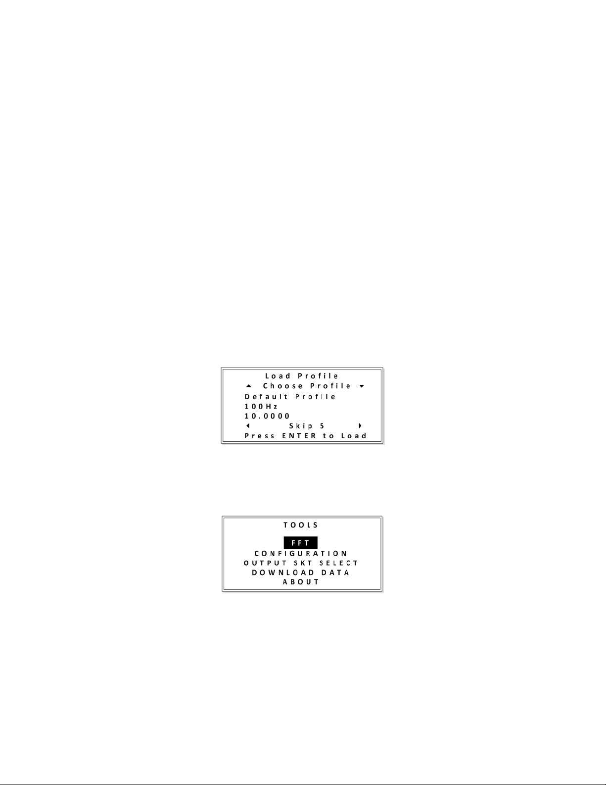
3.4.3. Profile selection
Profile selection is accessed by pressing the PROFILESmenu key. Scroll up or down with the arrow
keys to move between profiles and select the profile required by pressing the ENTERkey.
Figure 7: Profile selection
3.5. Tools
Access to the tools menu is accomplished by pressing the TOOLSkey.
Figure 8: Tools menu
Scroll up or down with the arrow keys to move the cursor (inverted text) to the required field, and press the
ENTER key.
3.5.1. FFT
IM4830B Rev B 10
October 9, 2019
The simulator features a basic FFT (Fast Fourier Transfer) function. This feature allows users to
identify the fundamental frequency and order of magnitude, of a complex vibration or similar
waveform. The signal is inputted into the simulator using the shared Tach / FCN BNC connector.
The tachometer output function is disabled once FFT mode has been selected. Users should
 Loading...