

Page 1
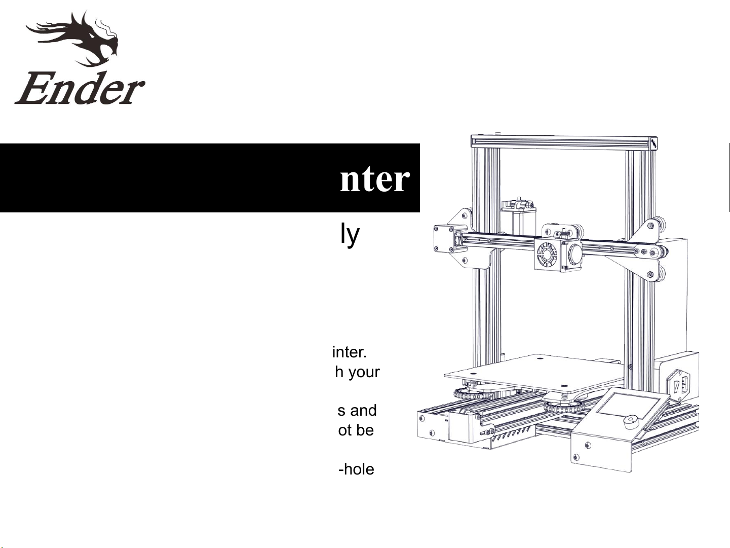
Ender-3 Pro 3D Printer
• Instructions for assembly
◆ This guide is for the Ender-3 Pro 3D printer.
◆ Select the correct input voltage to match your
local mains (230V or 115V).
◆ Because of software/hardware upgrades and
model differences, new revisions may not be
listed in this guide.
◆ Please plug the Power cord into a three-hole
power jack.
◆ Detailed instructions for use are available on
the SD card.
V1.0
Page 2
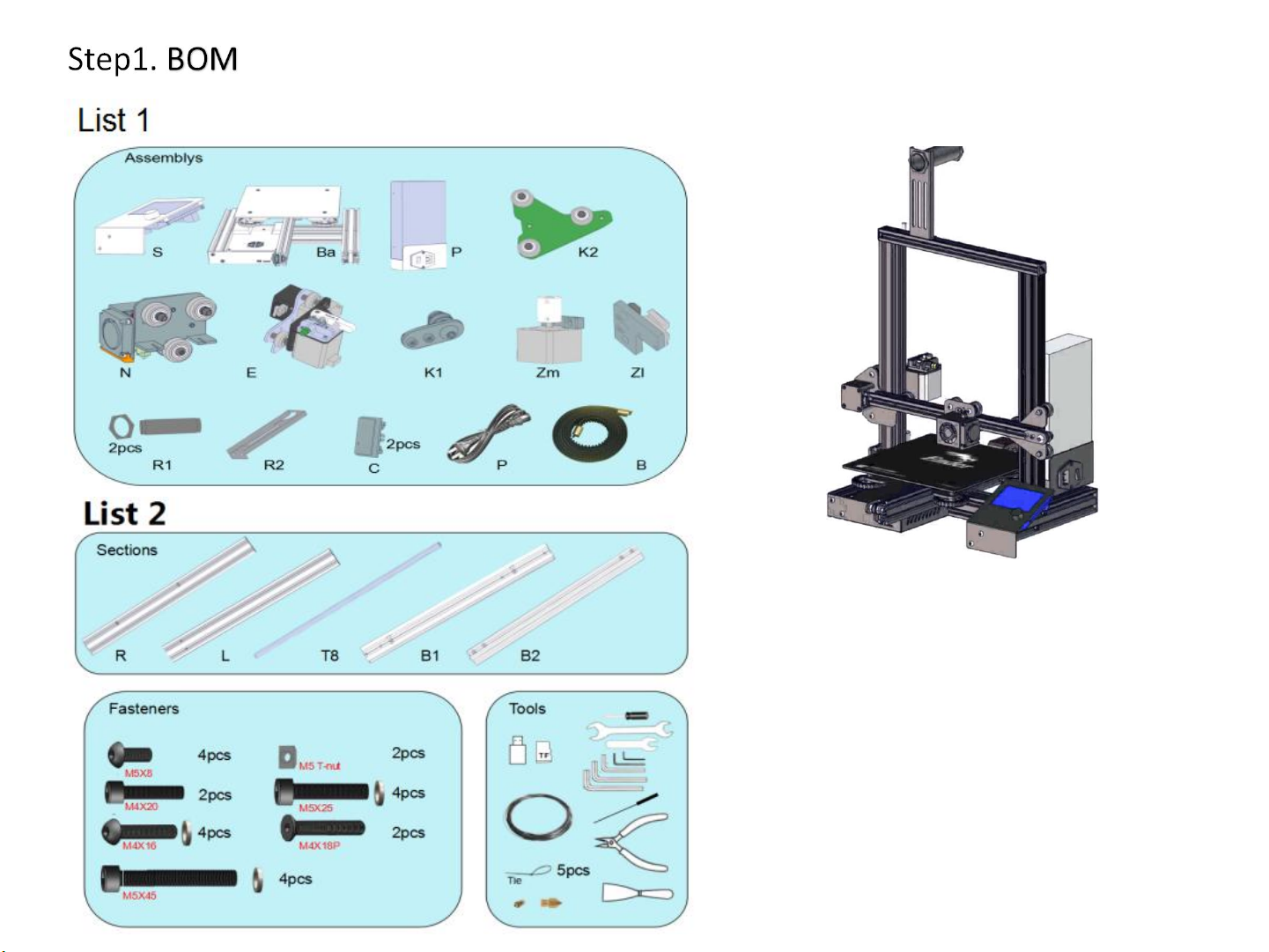
a. Remove the parts from the box and
remove any tape and padding from the
parts. Inspect the parts to make sure
they were not damaged in shipment.
b. Check the items on List 1 and List 2.
The wiring harness of component (Ba)
and component (N) has already been
connected.
1
Page 3
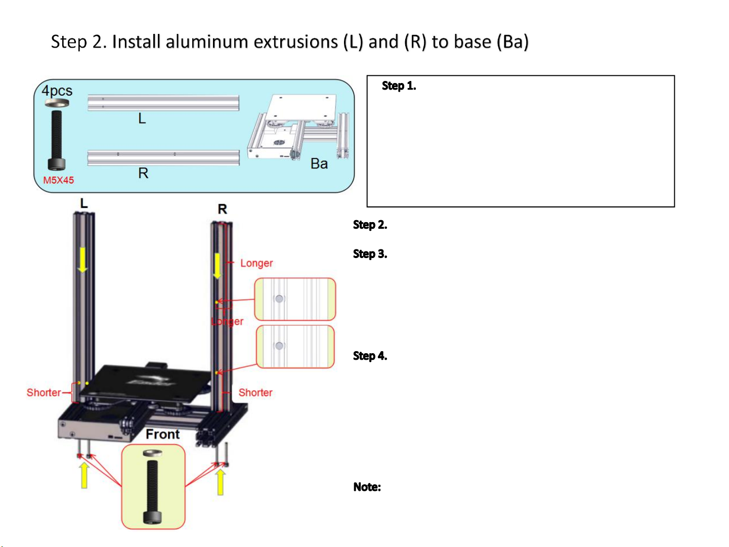
Prepare the following parts:
a. M5x45 socket head hex screws (4x)
b. M5 washer (4x)
c. Aluminum profiles (L) (1x)
d. Aluminum profiles(R) (1x)
e. Base (Ba) (1x)
f. 4mm Allen key
Keep the direction of the base (Ba) facing front;
Place the aluminum profile (L) vertically over the left side frame
of the base (Ba), be careful that the (L) profile has the threaded holes
with the short sides facing downwards. Using the M5x45 screws and
washers, pass through bottom hole of the aluminum profile at the left
side of the base (Ba), align the threaded hole at the bottom of the
aluminum profile (L), and use the Allen key to tighten the screws.
Place the aluminum profile (R) vertically over the right side
frame of the base (Ba). Note that the (R) profile has through holes with
the short sides facing downwards. Also note that the holes are to the
left (see diagram) to ensure that the aluminum profiles are oriented
correctly. , Using M5x45 screws and washers, pass them through
bottom hole of the aluminum profile at the right side of the base (Ba),
align the threaded hole at the bottom of the aluminum profile (R), and
use the Allen key to tighten the screws.
Raise the base frame above the table with two blocks (boxes,
books, etc.) Install the screws through the base frame into the
threaded holes in the extrusions.
2
Page 4
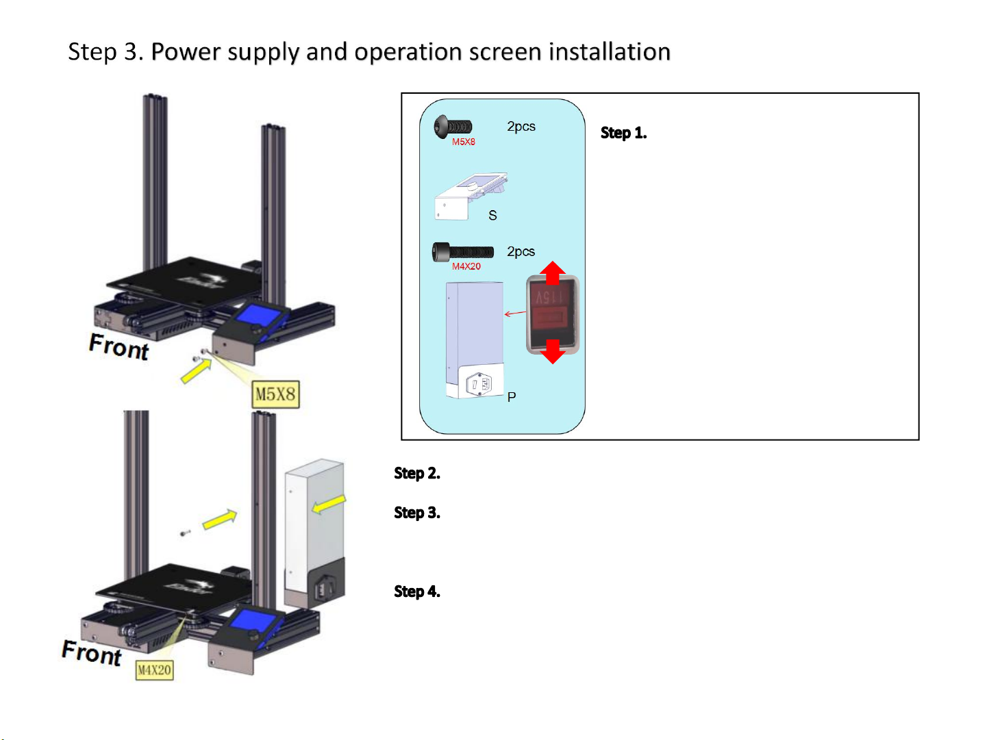
Prepare the following parts:
a. M5x8 hex drive rounded head screws (2x)
b. Operation screen assembly(S) (1x)
115V
230V
Keep the the base (Ba) facing towards you.
Align the hole at the bottom left of the operation screen with the
threaded hole of the aluminum profile on the right side of the base (Ba),
secure with M5x8 screws, and use the Allen key to tighten the screws.
Attach the switching power supply unit to the bottom as show on the
diagram to the left (button switch at the bottom right). Screw holes of the
switching power supply should pass through the holes of the aluminum
profile (R). Using M4x20 screws, pass through the front of the profile (R) and
use the Allen key to tighten the screws.
c. M4x20 socket head hex screws (2x)
d. Switching power supply assembly(P)(1x)
e. 3mm Allen key
f. *Select the correct input voltage to
match your local mains (230V or 115V).
3
Page 5
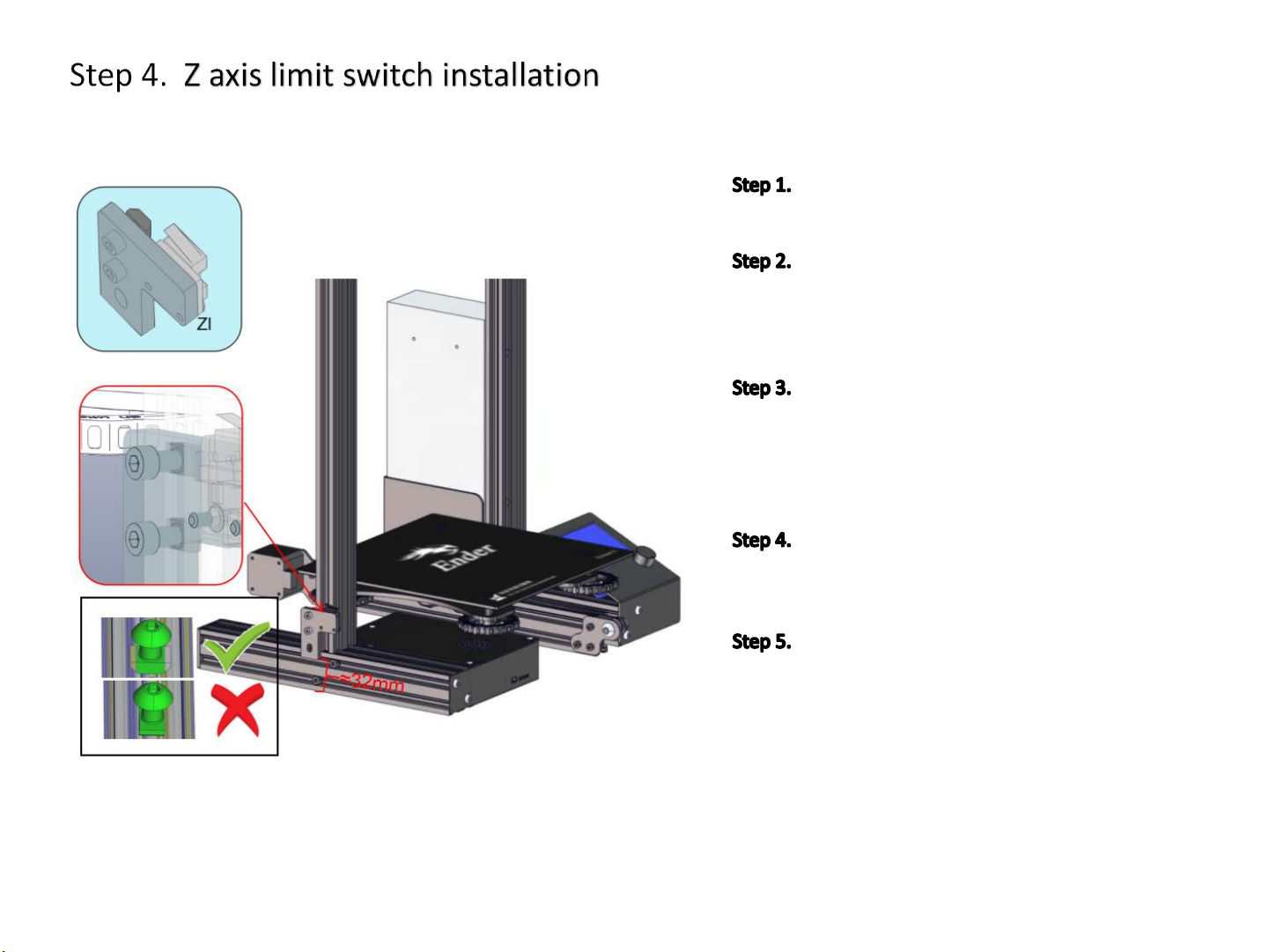
Front
Prepare limit switch assembly (ZI) and
3mm Allen key;
The direction of the base (Ba) stays at the
front, and the switch assembly (ZI) is mounted
on the left side of the base (Ba) (as shown in the
diagram on the);
Loosen the T-nut by hand until it is at the
end of the threads, but not so far it might fall off.
Then, fit into the slot in the aluminum profile.
When the bolt is tightened, the nut rotates 90
degrees and then grasps the inside of the slot.
Align the T-nut with the bottom
aluminum profile groove and secure with the
Allen key
The limit switch assembly (ZI) has a small
hook that attaches to the aluminum profile
underneath the base (Ba) (reference: about 32
mm from the bottom).
4
Page 6
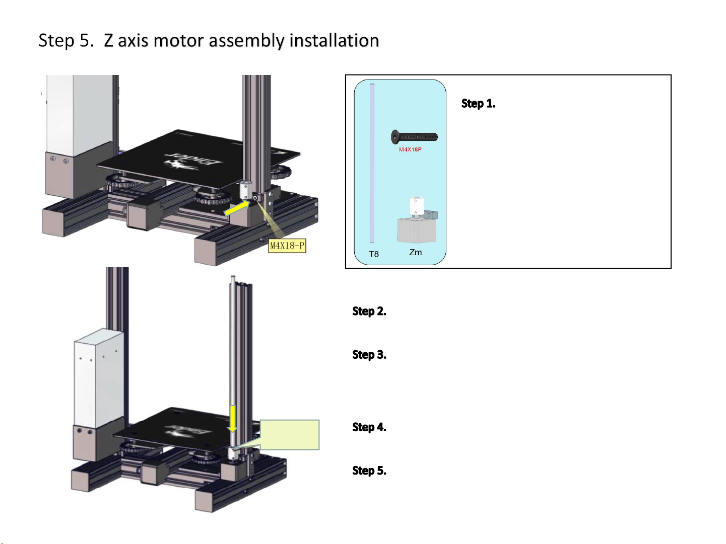
Prepare the following parts:
a. T8 Acme lead screw (1x)
b. M4x18 hex drive flat head screws
(2x)
c. Z-axis motor assembly (Zm) (1x)
Back
Back
Loosen
the screw
d. 2.5mm Allen key
Rotate base (Ba) 180°until the back is facing towards
you.
Position the hole of Z-axis motor assembly at the
threaded hole of the aluminum profile (L) in the base (Ba),
secure with M4*18 screws, and use the Allen key to tighten the
screws.
Use the Allen key to loosen the screws of the Z-axis
coupling to prepare for insertion of the lead screw.
Insert the T8 lead screw into the coupling, and tighten
the screw that was loosened in the previous step.
5
Page 7
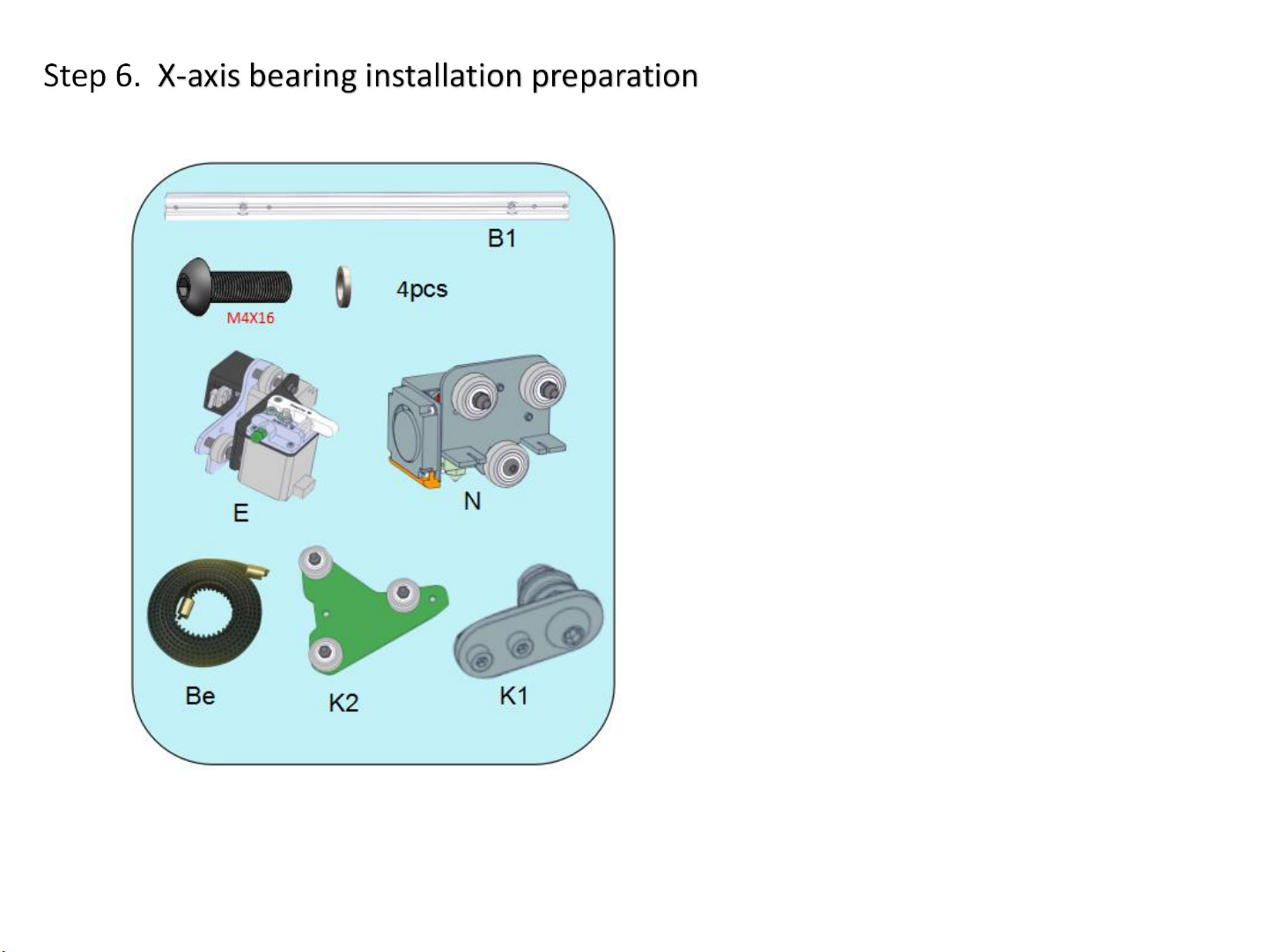
Prepare the following parts:
a. Aluminum profiles(B1)-(1x)
b.M4x16 Hex drive rounded head screws (4x)
c. M4 Washer (4x)
d. Extrusion assembly (E) (1x)
e. Nozzle kit (N)-(1x). The wiring harness of
component (N) and component (Ba) has already
been connected.
f. Timing belt(Be)-(1x)
g. Pulley assembly(K2)-(1x)
h. Belt tensioner(K1)-(1x)
i. 2.5mm Allen key
6
Page 8
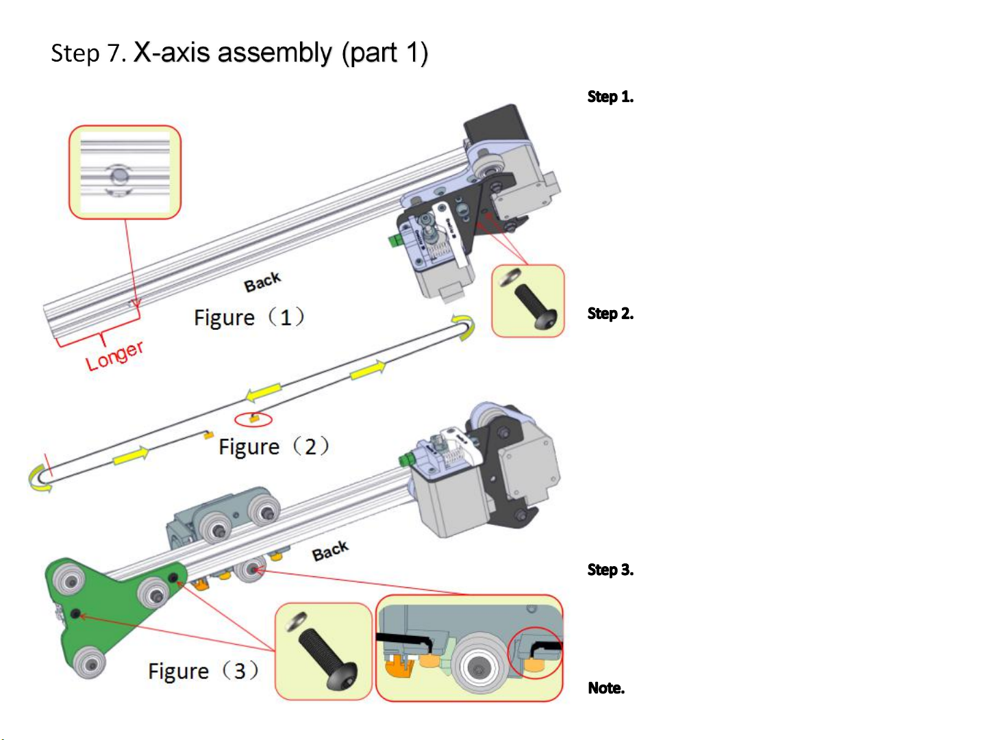
Assembly of aluminum profile (B1) and
extrusion assembly (E). Aluminum profile (B1) is
shown in the diagram on the left(1). Pay attention to
the position and direction of the large hole. Align the
hole of extrusion assembly (E) with the threaded
hole of aluminum profile (B1), it should be noted
that the hole has two plates, which aresecured with
M4*16 screws, and fixed to the second profile plate
and the aluminum profile (B1). Use the Allen key to
tighten the screws.
Adjust the direction of the nozzle kit(N) as
shown in Figure (3). Hold one end of the timing belt
in the slot on the right side underneath the nozzle
kit (N), and the other end in the path shown in
Figure (2). Go through the extrusion assembly (E),
bypass the synchronizing wheel, and slide the nozzle
kit (N) from the left into the aluminum profile when
the path of figure (2) completes three quarters (in
the red line position in Figure 2). Then, complete the
path of the belt as shown in Figure (2). Then, stick
the other end of the belt to the slot on the left side
below the nozzle kit (N).
Position the pulley assembly (K2) in the
position shown in Figure (3), align the threaded hole
in the aluminum profile on the left side of the profile
(B1), pass it with the M4*16 screw, and use the Allen
key to tighten the screws.
As you complete easy step, be sure to place
the parts according to the diagram on the left side.
7
Page 9
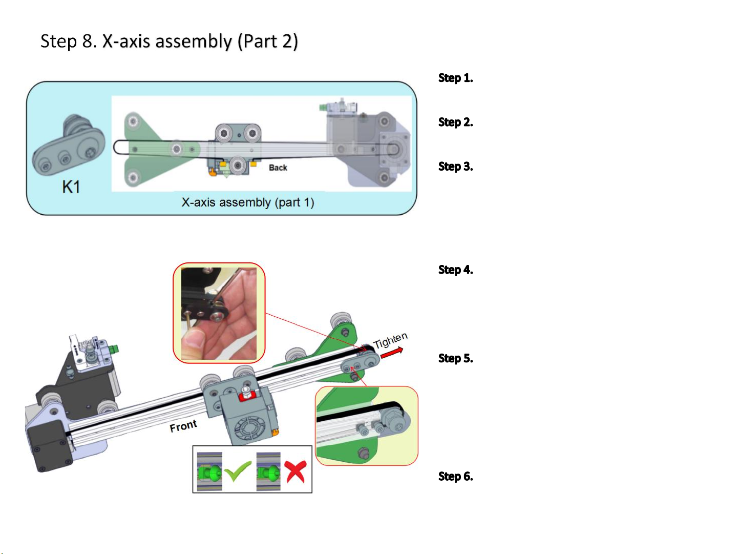
Prepare belt tensioner assembly (K1) and
3mm Allen key.
Rotate the X-axis assembly
180°horizontally.
Pick up the belt tensioner assembly (K1).
Loosen the T-nut by hand until it is at the end of
the threads, but not so far it might fall off. Then, fit
into the slot in the aluminum profile. When the
bolt is tightened, the nut rotates 90 degrees and
then grasps the inside of the slot.
Align the T-nut with the top aluminum
profile groove. Use an Allen key to tighten the
screw. Be careful not to tighten it all the way. Make
sure that the external actuator assembly (K1) can
be slid easily.
Align the belt so that one end fits over the
geared pulley in the extrusion unit (E) and one end
fits over the idler in the belt tensioning assembly
(K1). Apply tension in the direction of the red
arrow to the left and use an Allen key as a lever to
push the belt around the pulley. Tighten the belt
and then tighten the two screws.
Check the tension of the belt driving the Xaxis (on the gantry). The belt should be taut, with
no slack or slop.
8
Page 10
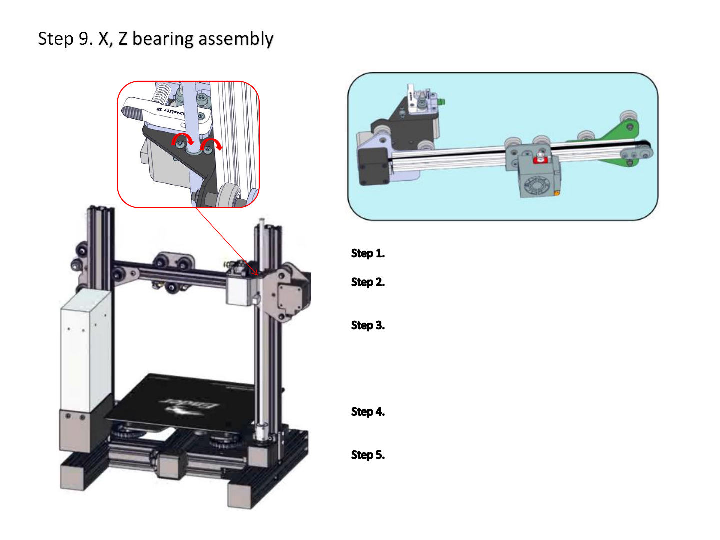
Back
Prepare 2mm and 2.5mm Allen key.
The direction of the base (Ba) keeps the end in front
and rotates the X-axis assembly horizontally by 180°.
Align the pulleys on both ends of the X-axis assembly
with the aluminum chute on the base (Ba). Align the screw
rod with the nuts in the extrusion assembly (E). Use the
appropriate Allen key to slightly loosen the screws that
holding the nuts. Mount the X-axis assembly on the base (Ba)
Manually apply force and slide the X-axis assembly up
and down to slowly lock the screws that secure the nut.
Slide the X-axis assembly up and down again to make
sure the slide is smooth. If it is not smooth, try loosening the
screws of the coupling slightly, turning the screws gently, and
slowly tightening the screws.
9
Page 11
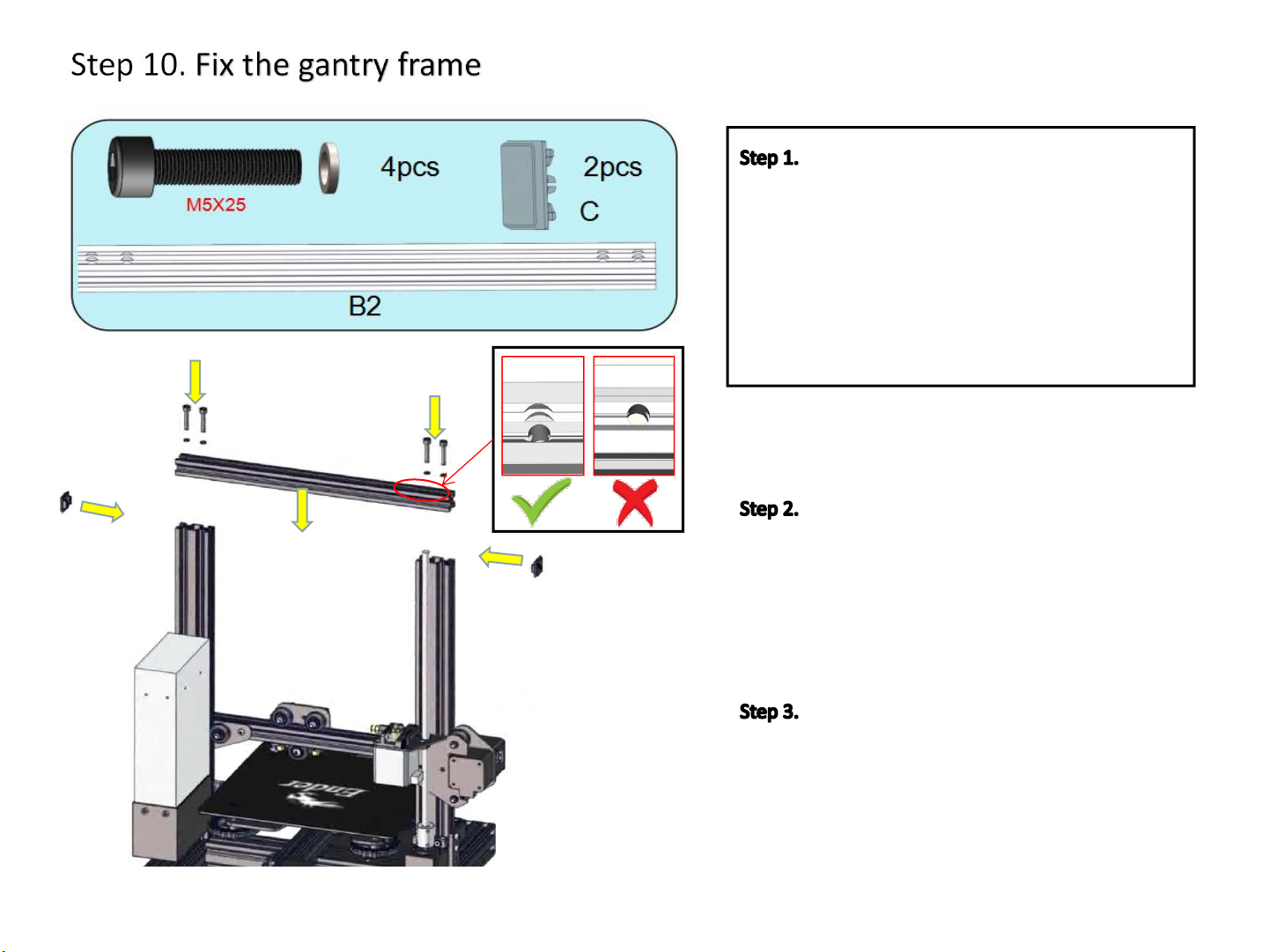
Prepare the following parts:
a. M5x25 socket head hex screws (4x)
b. M5 Washer (4x)
c. Profile end caps(C)-(2x)
d. Aluminum profiles (B2)-(1x)
e. 4mm Allen key
Take out the aluminum profile (B2), pay
attention to the counterbore hole at the top (see
the figure on the left), align the aluminum profile
(B2) hole with the threaded hole of the base (Ba),
use the M5*25 screw and washer, from the top go
through the aluminum profile hole(B2), use the
Allen key to tighten the screws.
Back
Take out the end cover (C) of the profile,
and attach it to the ends of the aluminum profile
(B2). Apply a little pressure and insert it into it. The
end face of the aluminum profile may be sharp. Be
careful not to scratch your hand.
10
Page 12
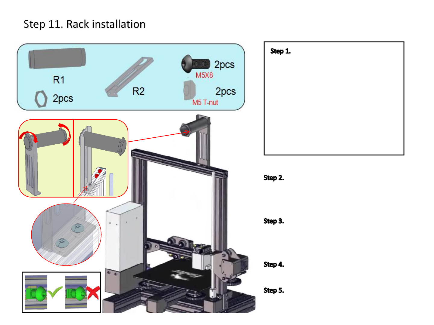
Prepare the following parts:
a. Plastic tube(R1)-(1x)
b. Plastic nut (2x)
c. Sheet metal bracket(R2)-(2x)
d. M5x8 Hex Drive Rounded Head Screws
(2x)
21
e. M5 T-nuts (2x)
f. 4mm Allen Key
Install one end of the plastic tube (R1)
on the sheet metal bracket (R2), hand-tighten
the plastic nut on the end of the plastic tube (R1)
and tighten by hand.
Use a M5x8 screw to pass through the
hole of the sheet metal bracket (R2). Handunscrew the M5 T-nut until it it is on the last
few threads of the screew.
Align the T-nut with the top aluminum
profile groove and tighten with an Allen key.
The Ender-3 mechanical part installation
has been completed.
11
Page 13
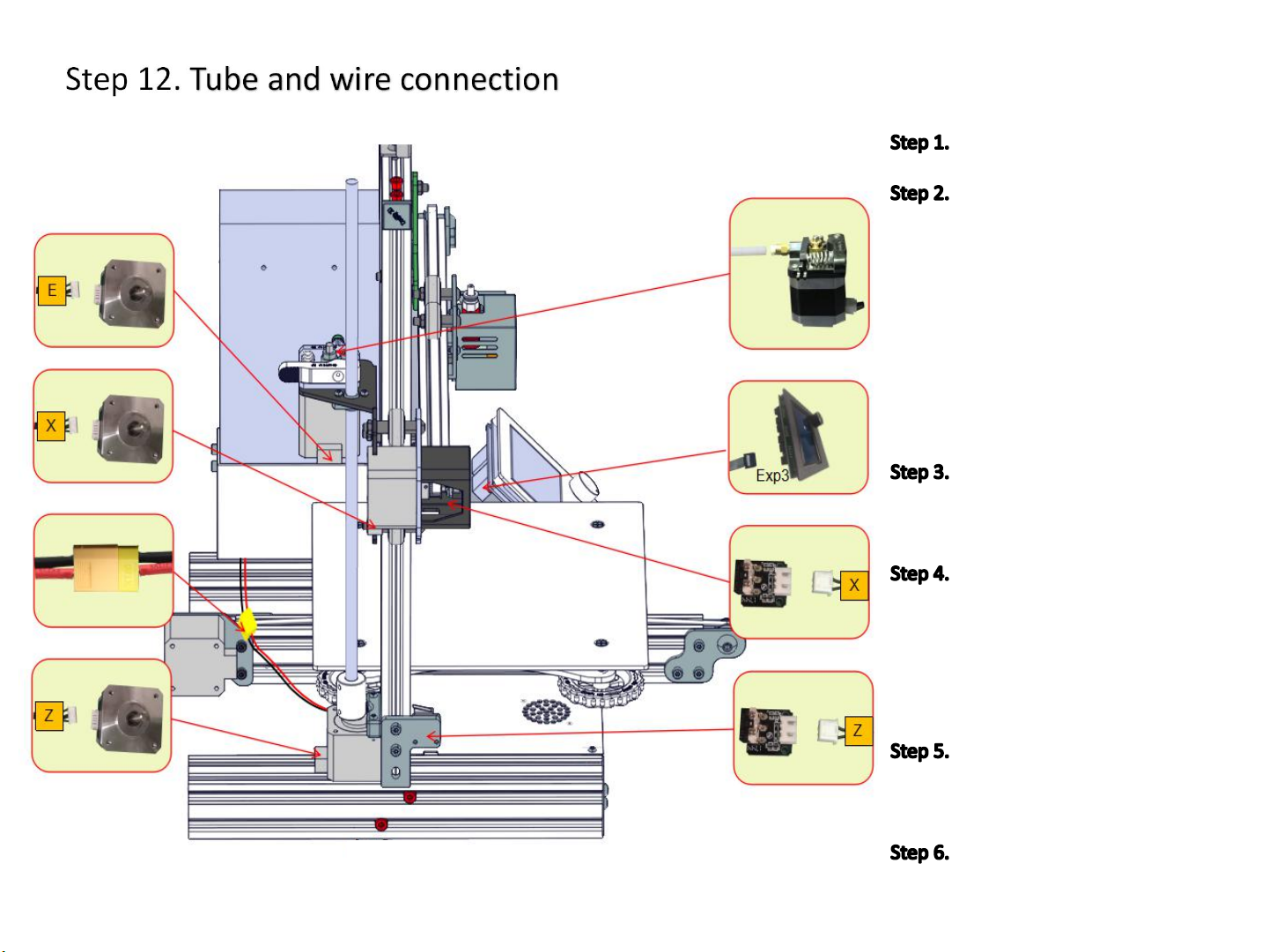
1
2
3
4
5
6
7
8
Rotate the printer by 90º
Find the letters on the
1/2/4/7/8 wire harnesses, as shown
on the left, and insert it according to
the position indicated by the red
arrow on the drawing. After the
insertion, gently pull on it to insure
it’s firmly seated. Note that the X/Z
wide plug corresponds to the motor,
and the narrow plug corresponds to
the limit switch
Red and black power
connector (3#) connector can be
directly inserted.
Connect the white PTFE
Bowden tube from the hot end to the
yellow tube upper coupler extruder
(See 5#). Insert the tube firmly into
the joint extruder and feel it slide in
and lock the position.
Left
The plug on the 6# harness is
inserted into the display board into
the jack marked "Exp3.
Check that all harnesses are
securely connected.
12
Page 14

Shenzhen Creality3D Technology CO.,LTD.
After-Sales Service Tel: +86 400 6133 882 +86 755 8523 4565
O f f i c i a l W e b s i t e : www.creality3d.cn
Co mpa ny Ad d re s s: 12th Floor, Building No.3, Jinchengyuan Industrial Area,
Tongsheng Community, Dalang Street, Longhua District, Shenzhen
 Loading...