

Endecotts Minor 200, Octagon 200, Octagon 200CL, Titan 450, Air Sizer 200 Operating Instructions Manual
...
WHEN PARTICLE SIZE MATTERS
Minor 200 Octagon 200 Octagon 200CL Air Sizer 200 EFL 300 Titan 450
SIEVING MACHINES
Operating Instructions


Content
Copyright © 2015 by Endecotts Ltd.
1
Contents
1. OPERATING INSTRUCTIONS NOTES……………………………….. 5
Warnings 5
Repairs 6
Safety 7
Safety instructions 7
Summary of safety instructions 8
Confirmation 10
2. TRANSPORT AND INSTALLATION………………………………… 11
Transport 11
Temperature fluctuations 11
Intermediate storage 11
3. OPERATING INSTRUCTIONS MINOR 200………………………… 13
Technical specifications 14
General Information 14
Specifications 15
Controls and Functions 16
Setting Up 17
Electrical connections 17
Start-up and commissioning 18
Certificate of CE-Conformity 20
4. OPERATING INSTRUCTIONS OCTAGON 200…………………… 21
Technical specifications 22
General Information 22
Specifications 23
Controls and functions 24
Setting Up 26
Electrical connections 26
Transport protection 27
Mount sieve clamping unit 28
Operating Instructions 29
Wet sieving 31
Certificate of CE-Conformity 32
5. OPERATING INSTRUCTIONS OCTAGON 200CL……………….. 33
Technical specifications 34
General Information 34
Specifications 35
Controls and functions 36

Content
2
Copyright © 2015 by Endecotts Ltd.
Setting Up 38
Electrical connections 38
Transport protection 39
Mount sieve clamping unit 39
Operating Instructions 41
Wet sieving 43
Certificate of CE-Conformity 44
6. OPERATING INSTRUCTIONS AIR SIZER 200…………………….. 45
Technical specifications 46
General Information 46
Specifications 47
Controls and functions 48
Setting Up 50
Electrical connections 50
Start-up and commissioning 51
Operating Instructions 52
Switching On and Off 52
Inserting the test sieve 52
Soft-faced mallet – Application and Use 52
Use of the machine for the intended purpose 53
Negative Pressure 55
Operating Software 55
Filter (Option) 56
Cleaning and service 56
Certificate of CE-Conformity 58
7. OPERATING INSTRUCTIONS EFL 300……………………………… 59
Technical specifications 60
General Information 60
Specifications 61
Controls and functions 62
Setting Up 64
Electrical connections 64
Transport protection 65
Mount sieve clamping unit 67
Operating Instructions 68
Wet sieving 70
Certificate of CE-Conformity 71
8. OPERATING INSTRUCTIONS TITAN 450…………………………. 73
Technical specifications 74

Content
Copyright © 2015 by Endecotts Ltd.
3
General Information 74
Specifications 75
Controls and functions 76
Setting Up 78
Electrical connections 78
Transport protection 79
Mount sieve clamping unit 81
Operating Instructions 82
Wet sieving 83
Certificate of CE-Conformity 84
GENERAL INFORMATION……………………………………………… 85
Use of Sieves 85
Test Sieves Available from Endecotts 85
EVALUATION SOFTWARE: SIEVEWARE……………………………… 87
General Information 87
Specifications 88
Function 88

4
Copyright © 2015 by Endecotts Ltd.
Copyright © 2015 by Endecotts Ltd.
All rights reserved, including the right to copy, distribute and translate this text. No part of this
document may be reproduced in any way wit hout written consent of Endecotts Ltd. nor may be
modified, copied or distributed with the help of electronic systems.
Manual can be subject to technical modification and errors.

1. Technical specifications 1. Technical specifications
Copyright © 2015 by Endecotts Ltd.
5
1. Operating instructions notes
These operating instructions for the Endecotts test sieving machines give all
necessary information on the sections mentioned in the contents.
They give instructions to the target group(s) defined in the respective sections for
safe, correct handling of the Endecotts machines. It is important that each target
group(s) is (are) familiar with the relevant section, in order to ensure safe, reliable
handling of the machine according to its intended use.
This technical documentation is for use as a reference work and as a learning aid.
The information of each individual product (sieving machines) is complete within
their section.
Repair instructions are not included in this manual. If repairs are necessary please
contact your supplier or Endecotts Ltd directly.
Endecotts Ltd www.Endecotts.com
Warnings
The following signs are used to warn of hazards:
Personal injuries
Material damage

1. Setting up 1. Setting up 1. Setting up
6
Copyright © 2015 by Endecotts Ltd.
Repairs
This operating manual does not contain any repair instructions.
In the interests of your own safety, repairs should only performed by Endecotts Ltd or
an authorised representative (service technician).
In this case, please notify the following:
The local Endecotts representative
Your supplier
Endecotts Ltd direct
Your address for service:

1. Technical specifications 1. Technical specifications
Copyright © 2015 by Endecotts Ltd.
7
Safety
Target group:
All persons concerned with the machine in any way.
The entire Endecotts machine range is a modern, highly efficient product of
Endecotts Ltd, corresponding to state of the art works. If the machine is used
according to the intended purpose with knowledge of this technical
documentation it is completely safe and reliable to operate.
Safety instructions
As the operator it is your duty to ensure that all persons charged with working on
the Endecotts machine:
• Have read and understood all the instructions on safety,
• Before beginning work know all the instructions and regulations for the target
group relevant to their work,
• Have access to the technical documentation for this machine at all times,
without problems.
• New personnel should be familiarised with safe, proper handling of the
machine before beginning work on the Endecotts machine, either by verbal
instruction from a competent person or through this technical documentation.
• Improper operation can cause injury to persons or damage to the equipment.
You are responsible for your own safety and that of your employees.
• Ensure that unauthorised persons have no access to the Endecotts machine.
For your own protection have your employees confirm that they have been
instructed in operation of the Endecotts machine. The draft of a suitable form is
given at the end of the section on safety.
We exclude claims for damages in any form for damage to persons or
property caused through non-observance of the following safety
instructions.

8
Copyright © 2015 by Endecotts Ltd.
1. Setting up
Summary of safety instructions
Safety instructions
Technical data
Do not make any changes to the machine and use only spare parts and
accessories which have been approved by Endecotts.
The declaration of conformity to the European directives by Endecotts will
otherwise lose its validity. Furthermore this will result in the loss of any kind of
guarantee claims.
Packing
Please keep the packing material during the guarantee period in case of a
complaint your guarantee claim will be at risk if the machine is returned in
inadequate packing.
Transport
The Endecotts machine must not be knocked, shaken or thrown during
transport; otherwise the electronic and mechanical components may be
damaged.
Temperature fluctuations
If subjected to high temperature fluctuations (e.g. during transport by plane) the
Endecotts machine must be protected against condensed water. If not damage to
the electronic components may be caused.
Supply schedule
If the delivery is incomplete and/or transport damage has occurred, you must
immediately notify the transport agent and Endecotts Ltd (within 24 hrs.). It is
possible that later complaints may not be considered.
Ambient temperature
If the ambient temperature is exceeded or drops below the normal value the
electrical and mechanical components may become damaged and the
performance data can change to an unknown degree.
We exclude claims for damages in any form for damage to persons or property
caused through non-observance of the following safety instructions.

1. Technical specifications
Copyright © 2015 by Endecotts Ltd.
9
1. Technical specifications
Atmospheric humidity
At high atmospheric humidity the electrical and mechanical components may
become damaged and the performance data can change to an unknown degree.
Installation / transport protection - IMPORTANT
If the machine is operated with the transit bolts, or is transported without transit
bolts, mechanical components may become damaged.
Electrical connection / connecting the mains power supply
If the values given on the rating label are not observed electrical and mechanical
components may become damaged.
Wet sieving
Never operate your Endecotts machine directly in water.
Danger through current surge.
During wet sieving always operate your Endecotts machine connected to a
mains socket which is protected by an FI protective (safety) switch.
The water quantity added should always be dosed in such a way that the sieve
surface is only just wetted.
Sieving aids
Make sure that the wire mesh of the sieves is not excessively stretched through
overloading with sieving aids, since this will impair the precision of your test
sieves.
Damage may occur if the
shaker is allowed to operate with a loose clamping
plate.

10
Copyright © 2015 by Endecotts Ltd.
1. Setting up
Cleaning
Do not clean the Endecotts machine under running water.
Danger to life through current surge.
Use only a cloth moistened with water; solvents are not allowed.
Wearing parts
These operating instructions do not include repair instructions.
For your own safety, repairs should be carried out only by Endecotts Ltd or an
authorised agency or Endecotts service technicians.
Confirmation
I have read and taken note of the sections – preliminary
comments and safety
________________________________________________
Signature of operator
________________________________________________
Signature of service technician

1. Technical specifications
Copyright © 2015 by Endecotts Ltd.
11
1. Technical specifications
2. Transport and installation
Packing has been adapted to the transport method and conforms to generally applicable
packing guidelines.
Packing
Please keep the packing material during the guarantee period in case of a
complaint, your guarantee claim will be at risk if the machine is returned in
inadequate packing.
Transport
The Endecotts Machine must not be knocked, shaken or thrown during transport;
otherwise the electronic and mechanical components may become damaged.
Please make sure you have removed all transit bolts before using the Endecotts
machine.
Specific operating instructions can be found on the relevant pages
for every single
Endecotts machine in this manual.
Temperature fluctuations
If subjected to high temperature fluctuations (e.g. during transport by plane) the
Endecotts machine
must be protected against condensed water. If not damage to
the electronic components may be caused.
Intermediate storage
Ensure that the Endecotts machine is kept dry also during intermediate storage.

12
Copyright © 2015 by Endecotts Ltd.
1. Setting up

1. Technical specifications
Copyright © 2015 by Endecotts Ltd.
13
1. Technical specifications
3. Operating instructions:
Minor 200

14
Copyright © 2015 by Endecotts Ltd.
1. Setting up
Technical specifications
SIEVE SHAKER MODEL:
Minor 200
General Information
The Minor 200 has been developed and manufactured to combine low cost with the benefits of a welldesigned and engineered shaker. It incorporates many features usually found only on larger, more
expensive models. It is ideal for the use in laboratories and a plant since it is compact and genuinely
portable (weighing only 16 kg).
The sieve stack is held firmly in position by a clamping belt system. Removing it allows the whole
unit to be stored in a space less than 200 mm high. There are no rotating parts in the Minor 200 consequently it is quiet in operation and maintenance free.
Advantages
• Electromagnetic drive for quiet and virtually maintenance free operation
• Compact and portable (weighing only 16 kg)
• Requires only small storage space due to small footprint
• Easily removable clamping belt system (included)
• Easy to use
• Different voltages available
• Complies with the requirements of AASHTO T 27
The Minor 200 is not recommended for any wet sieving operations!
Do not make any changes to the machine and use only spare parts and
accessories approved by Endecotts Ltd.
The declaration of conformity to the European directives by Endecotts
will otherwise lose its validity.
Furthermore this will result in the loss of any kind of guarantee claims.

1. Technical specifications
Copyright © 2015 by Endecotts Ltd.
15
1. Technical specifications
Specifications
Range 38 µ
m to 125 mm
Drive / sieving motion electromagnetic
Max. Batch / feed capacity 3 kg
Max. Number of fractions 8 full height / 16 half height (200 mm or 8”)
Amplitude ~ 1.6 mm* fixed
Speed 3,000 min-1 at 50 Hz
Time display analogue, 0 - 60 min or continuously
Suitable for dry sieving yes
Suitable for wet sieving no
Sieve diameter 100 / 200 mm or 3” / 8"
Clamping device clamping belt system (included)
Model bench top
Protection code IP 20
Electrical supply different voltages available
Power connection 1-phase
Ø x H 262 x 126 mm
Net weight 16 kg
(*) depending on load
16
Copyright © 2015 by Endecotts Ltd.
1. Setting up
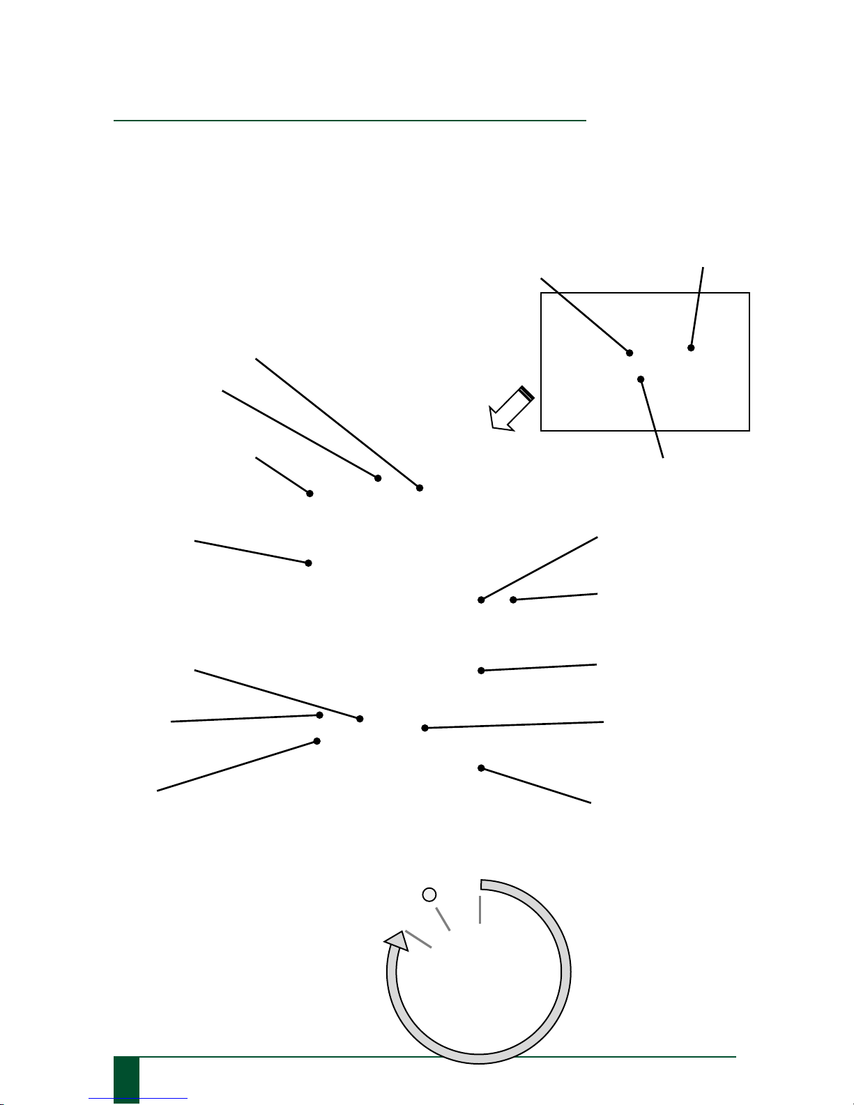
Controls and Functions
Operators should be familiar with and fully understand the controls and indicators before
operating this machine.
PLUG
(Removable knob for lid)
CLAMP PLATE
CLAMPING LATCH
ADJUSTABLE CAM
BUCKLES
MAINS SWITCH
STRAP
COVER
BASE
ANTI-VIBRATION FEET
LED (indicates
mains power to
instrument)
PROCESS TIMER
On /Off Switch
LOCATION PLATE
SIEVE STACK
MAINS POWER
CONNECTION
FUSE HOLDER
60 MIN
OFF
CONTINUOUSLY

1. Technical specifications
Copyright © 2015 by Endecotts Ltd.
17
1. Technical specifications
Setting Up
Electrical connections
Ensure that the voltage and frequency on the rating label, at the rear of the
shaker, correspond with the local electrical mains supply.
• Connect the Minor 200 to the power supply using the connection cable
provided.
Do not connect to any other supply other than stated on the rating label,
otherwise electrical and mechanical components can be damaged.
Ambient temperature: 5°C to 40°C
If the ambient temperature is exceeded or drops below the specified value
the electrical and mechanical components may become damaged and the
performance data can change to an unknown degree.
Atmospheric humidity:
Maximum relative humidity 80% at temperatures up to 31°C, with linear reduction
down to 50% relative humidity at 40°C.
At high atmospheric humidity the electrical and mechanical components
may become damaged and the performance data can change to an
unknown degree.
• Mains power connection
Mains power connection with integral line filter. Ensure the IEC connector on the mains
lead is pushed fully into the mains inlet at the rear of the machine.
• L.E.D (Mains Connected Indication)
This is a green L.E.D that indicates electrical power is connected to the equipment. The
L.E.D is illuminated when the IEC connector is pushed fully into the inlet and power is
switched on at the local outlet.
If the L.E.D fails to light with the local outlet switch in the ON position then the fuse (see
“Fuse holder”) has blown or power is not present at the mains.
• Fuse (Fuse Holder)
The fuse is a ceramic fuse. It is important that the recommended current rating is not
exceeded and the fuse is replaced with the same type and size. If the fuse blows after
replacement then a fault exists in the equipment which must be rectified.

18
Copyright © 2015 by Endecotts Ltd.
1. Setting up
• Process Timer
The process timer is a mechanical 0-60 minute timer which also provides continuous
running if desired. Operating periods are increased by rotating clockwise and decreased by
rotating anticlockwise (the timer will commence timing down as soon as the knob is
released, regardless of electrical power being connected or not). When the knob is turned
anti-clockwise from off position to the continuous running mark, the shaker will continue
running until the knob is returned to the off position.
Start-up and commissioning
The shaker should be set up according to the following procedure.
The following items should be removed from the case and checked before the shaker is operated
(Take care the shaker weighs 16 kg):
• 1 off Set-up Instructions.
• 1 off Instruction Manual.
• 1 off Mains Cable.
• 1 off Clamp Plate Assembly.
• 1 off Minor Shaker fitted with Clamping Straps and Buckles.
Position the shaker on a level, rigid and robust bench, suitable for the operation of the sieve shaker.
Being placed on a level surface ensures symmetrical distribution of the sample over the sieves, during
operation.
Operating Instructions
1. Place the receiver centrally on the location plate..
2. Stack the required test sieves on top of the receiver (min. 1x receiver + 2x sieves + 1x lid).
3. Put the sample in the top sieve and fit the lid.
In order to guarantee exact results under fast sieving conditions, the quantity of material to be sieved
should be adapted to the sieve diameter and the nominal mesh size.
More detail information is displayed in our “TEST SIEVING MANUAL”.
4. Place the clamp plate on top of the sieve stack.
5. Raise the clamping latch lever upwards to expose the latch hook.
1. Technical specifications
Copyright © 2015 by Endecotts Ltd.
19
1. Technical specifications
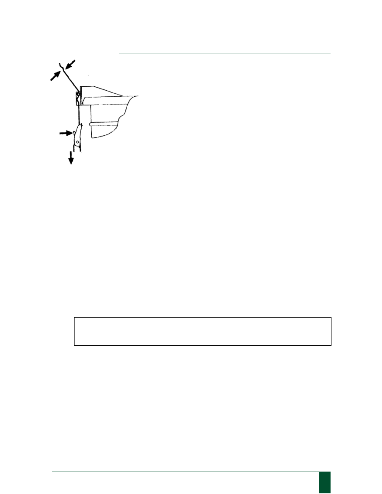
While holding the clamping latch using one hand, press the lever
on the cam buckle with the other hand. Slide the cam buckle along
the clamping strap until it can be engaged into the latch hook.
Release the cam buckle, pull the lose end of the strap downwards
to partially tension the strap.
Do not over tension. The clamping latch lever will remain in the
raised position 20-30 degrees from the vertical when partially
tensioned. Repeat these actions for the second clamping latch.
6. Press both levers down, closing the latches to clamp the sieve
stack. Do not use excessive force, it may be necessary to
loosen the straps slightly to secure.
7. Repeat previous action to release or increase tension in the strap as necessary to ensure a firm
grip!
The Endecotts Minor 200 sieve shaker is maintenance free other than keeping external surfaces clean.
Cleaning - The machine can be cleaned with a soft damp cloth using a solution of water and a mild
liquid detergent. Do not use any solvents for cleaning
Fuse - Should a fuse require replacement this must be of the identical type and rating as the original!
The rating of the fuse is marked on a label above the fuse. Disconnect from the mains supply. Remove
the blown fuse and place the new fuse in.
Do not over tighten
Damage may occur if the shaker is allowed to operate with a loose clamping plate.
Endecotts machines are fully tested and factory checked before shipping to customers. No parts
require lubrication or resetting unless disturbed. The sieve shaker has been constructed and factory
tested to ensure correct operation when connected to the specified electricity supply indicated on the
machines rating label.
All replacement parts must be ordered by quoting the shaker serial number and the correct part
number. Use of unapproved spares or any alteration to the machine would invalidate all warranties
and compliance with the European directives for ‘CE’ marking.

20
Copyright © 2015 by Endecotts Ltd.
1. Setting up
CERTIFICATE OF CE-CONFORMITY
TEST SIEVE SHAKER
MINOR 200
Certificate of CE-Conformit y according to:
EC Mechanical Engineering Directive 2006/42/EC
Applied harmonized standards, in particular:
EN ISO 12100 Security of machines
EC Directive Electromagnetic Compatibility 2004/108/EC
Applied standards, in particular:
EN55011:2009+A1:2010, Group 1, Class B Radio disturbance characteristics –
Limits and methods of measurement
EN 61000-3-2:2006+A1:2009+A2:2009
EN 61000-3-3:2008
EN61326-1:2006
Additional applied standar ds, i n particular
EN 61010 Safety prescriptions concerning measuring, operating, controlling and laboratory equipment
Authorised for the compilation of technical documents:
Endecotts Ltd (technical documentation)
The following records are held by Endecotts Ltd in the form of Technical Documentation:
Detailed records of engineering development, construction plans, study (analysis) of the measures required
for conformity assurance, analysis of the residual risks involved and operating instructions in due form
according to the approved regulations for preparation of user information data.
The CE-conformity of the Endecotts Test Sieve Shaker Type Minor 200 is assured herewith.
In case of a modification to the machine not previously agreed with us as well as the use of not licensed
spare parts and accessories this certificate will lose its validity.
Endecotts Ltd London, July 2014

1. Technical specifications
Copyright © 2015 by Endecotts Ltd.
21
1. Technical specifications
4. Operating instructions:
Octagon 200

22
Copyright © 2015 by Endecotts Ltd.
1. Setting up
Technical specifications
SIEVE SHAKER MODEL:
Octagon 200
General Information
The sieve shaker Octagon 200 is suitable for all sieving tasks in laboratories as well as onsite and
provides optimum sieving action for fast and reproducible results.
It is robust, compact and sufficiently lightweight to be portable. Its electromagnetic drive combined
with a 3D sieving motion ensures excellent separation efficiency in a short amount of time.
A digital display as well as a quick-release clamping system makes operation very easy and
straightforward.
Advantages
• Easy-to-use sieve clamping system
• Accepts up to 8 full height 200 mm or 8" diameter sieves
• Suitable for dry and wet sieving
• 10 amplitude settings and digital timer
• 3D sieving motion allows for high separation efficiency and non-blinding
sieving action
• Different voltages available
• No mechanical moving parts
• Compact and portable
Do not make any changes to the machine and use only spare parts and
accessories approved by Endecotts Ltd.
The declaration of conformity to the European directives by Endecotts
will otherwise lose its validity.
Furthermore this will result in the loss of any kind of guarantee claims.

1. Technical specifications
Copyright © 2015 by Endecotts Ltd.
23
1. Technical specifications
Specifications
Range 20 µ
m to 125 mm
Drive / sieving motion electromagnetic 3D
Max. Batch / feed capacity 3 kg
Max. Number of fractions 8 full height / 16 half height (200 mm or 8”)
Amplitude 0 - 3 mm digital setting in 10 steps
Speed 3,000 min-1 at 50 Hz
Time display digital, 0:10-99:50 min
Interval operation yes (one mode)
Suitable for dry sieving yes
Suitable for wet sieving yes
Serial interface -
Sieve diameter 100 / 200 mm or 3”/ 8''
Max. Height of sieve stack up to 450 mm
Clamping device quick-release clamping system (included)
Model bench top
Protection code IP 54
Electrical supply different voltages available
Power connection 1 – Phase
W x H x D 418 x 232 x 435 mm
Net weight 35 kg
Standards CE
Noise characteristic values:
Example 1:
Emission value related to workplace LpAeq = 63 dB (A)
(Operating conditions: Material to be sieved = quartz sand, grain size < 1mm, 5 sieves Amplitude =
1.5 mm)
Example 2:
Emission value related to workplace LpAeq = 67 dB (A)
(Operating conditions: Material to be sieved = quartz sand, grain size < 1mm, 5 sieves Amplitude =
3 mm)
24
Copyright © 2015 by Endecotts Ltd.
1. Setting up
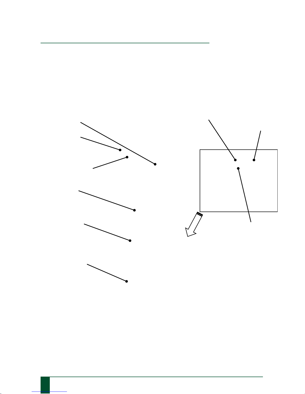
Controls and functions
The sieve shaker should be placed on a level surface to ensure symmetrical distribution of the sample
over the sieve mesh. The surface should be rigid and robust where vibration will not cause problems.
Operators should be familiar with and fully understand the controls and indicators before
operating this machine. This should be done in conjunction with the diagram below and control
panel description.
CLAMP PLATE
CLAMP HAND
WHEELS
SIEVE STACK
LARGE PLAIN
CLAMP WASHERS
ROUND
CLAMP RODS
MAINS SWITCH
MAINS POWER CONNECTION
FUSE HOLDER
CONTROL PANEL
1. Technical specifications
Copyright © 2015 by Endecotts Ltd.
25
1. Technical specifications
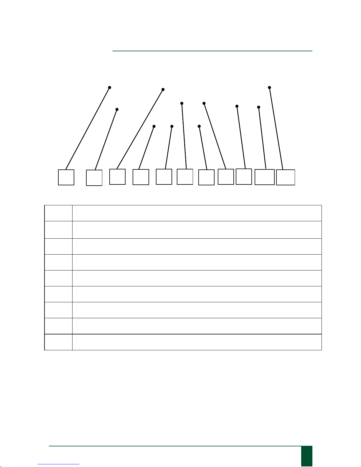
1 LED light to indicate interval operation ON.
2
Interval mode button M1 switches interval operation ON/OFF,
upper LED lights up; 10 seconds on, 2 seconds off
3 Display shows the preselected sieving time, 00:10 – 99:50 min.
4 LED light to indicate START button “>” ON
5 Start the machine by pressing the START button “>”.
6 & 8 “˅“ and “˄” button reduces/increases the sieving time, 00:10 – 99:50 min
7
Stop the machine by pressing the STOP button “
□“.
9 & 10 “˅“ and “˄” button reduces/increases the amplitude, in 10 steps
11 10 LED’s for the Power bar indicating amplitude setting in 10 steps
6
7 4 1
5
3
11 2 9
10
8

26
Copyright © 2015 by Endecotts Ltd.
1. Setting up
Setting Up
Electrical connections
* The voltage and frequency for the Octagon 200 is
given on the rating label.
* Ensure that the values agree with the existing power
supply.
* Connect the Octagon 200 to the power supply using
the connection cable provided.
* When connecting the power cable to the mains
external fusing is necessary according to the
regulations of the installation location
Do not connect to any other supply other than stated on the rating label,
otherwise electrical and mechanical components can be damaged.
Ambient temperature: 5°C to 40°C
If the ambient temperature is exceeded or drops below the specified value
the electrical and mechanical components may become damaged and the
performance data can change to an unknown degree.
Atmospheric humidity:
Maximum relative humidity 80% at temperatures up to 31°C, with linear
reduction down to 50% relative humidity at 40°C.
At high atmospheric humidity the electrical and mechanical components
may become damaged and the performance data can change to an
unknown degree.

1. Technical specifications
Copyright © 2015 by Endecotts Ltd.
27
1. Technical specifications
Transport protection
Place the Octagon 200 on a stable laboratory bench, since otherwise unpleasant vibrations will
be transmitted. Being placed on a level surface ensures symmetrical distribution of the sample
over the sieves, during operation.
• Unscrew the two hexagon screws (transit bolts) on the bottom of the sieve shaker with
an open ended spanner until the sieve plate is movable.
• Keep hexagon screws (transit bolts) for possible transport at a later date.
If the machine is operated with the transit bolts
, or is transported without
transit bolts, mechanical components may become damaged.
Reusing transit bolts
• Dismount the clamping unit.
• Screw the hexagon screws (transit bolts) into the two holes on the bottom of the sieve
shaker and tighten with open ended spanner until the sieve plate is no longer movable.

28
Copyright © 2015 by Endecotts Ltd.
1. Setting up
Mount sieve clamping unit
Fit one M12 nut onto each clamp rod selected for use, then
screw the pair of clamp rods into the location plate and tighten
the locknuts.
Place the two large plain washers over the 20 mm threads of the clamp sleeves. These can be seen
protruding vertically from the two side lugs on the clamp plate. Screw the two hand wheels
loosely onto the 20 mm threads; leave a gap of 5 mm between the large washer and the hand
wheel face. Do not tighten right down at this point.
WASHER
HAND WHEEL
SIDE
HANDLE
LEVER

1. Technical specifications
Copyright © 2015 by Endecotts Ltd.
29
1. Technical specifications
Operating Instructions
1. Place the receiver centrally on the location plate in the appropriate recess.
2. Stack the required test sieves on top of the receiver (min. 1x receiver + 2x sieves + 1x lid).
3. Put the sample in the top sieve and fit the lid
In order to guarantee exact results under fast sieving conditions, the quantity of material to be sieved
should be adapted to the sieve diameter and the nominal mesh size.
More detailed information is displayed in our “TEST SIEVING MANUAL”.
4. Align the locking assemblies in figure 1 the two side lugs of the clamp plate with the round
clamp rods. Slide the clamp plate down squarely onto the lid at the top of the sieve stack.
Ensure that the clamping hand wheels at the top (figure 2) are loose and the locking assemblies are
fully pushed down. There should be a 5mm gap between the large plain washer and the face of the
hand wheel.
Place one hand on the top of the clamp plate (figure 3) and hold square while locking one side handle
lever. Repeat for the opposite side handle lever.
The side handle levers can be set vertically downwards by pressing on the Red button and pulling
the handle outwards to release (figure 4). Turn the handle to a safe, convenient angle downwards and

30
Copyright © 2015 by Endecotts Ltd.
1. Setting up
release to engage the teeth. Screw the two clamping hand wheels down simultaneously to ensure the
clamping plate is square.
Continue until the hand wheels are tight against the internal stop. Hand tightness must be exerted so
that the assembly does not loosen during vibration.
The locking side handle levers and clamping hand wheels must be tightened sufficiently to ensure
that the sieves and receiver are clamped securely during operation.
5. Set time, interval and amplitude.
6. Press START
Damage may occur if the shaker is allowed to operate with a loose clamping plate.

1. Technical specifications
Copyright © 2015 by Endecotts Ltd.
31
1. Technical specifications
Wet sieving
The Wet Sieving Adaptor Kit is supplied as an optional extra for 200 mm or 8” diameter sieves and
should be ordered separately.
The Wet Sieving Adaptor Kit consists of the following items:
• 1 off Special Wet Sieving Clamp Plate.
• 1 Set off O-ring Seals (One required for
each sieve in the stack.)
• 1 off Special Wet Sieving Receiver with a spout.
(Specify for 200 mm or 8” diameter sieves )
The O-ring seals are fitted on to the outside of the bottom rim of each sieve, which means the
sieves are stacked onto each other and they form a seal.
The bottom sieve is placed on the special receiver with a spout.
A nylon hose tail must be fitted and must have a suitable length of hose fitted to drain into a
convenient drainage point.
Fit a suitable length of hose to the spout to drain into a convenient drainage point.
The clamp plate is usually supplied with the rose reversed to avoid damage. Undo and reverse,
so that the rose head is on the inside. Remove the lid from the sieve stack and replace the standard
clamp plate with the wet sieving clamp plate. Fit a suitable length of hose to the inlet of the rose on
the clamp plate and connect to the fluid supply with flow regulation.
Never operate your Sieve shaker directly in water.
Danger through current surge.
During wet sieving always operate your Sieve shaker connected to a mains socket
protected by an FI protective (safety) switch.
The water quantity added should always be dosed in such a way that the sieve
surface is only just wetted.

32
Copyright © 2015 by Endecotts Ltd.
1. Setting up
CERTIFICATE OF CE-CONFORMITY
TEST SIEVE SHAKER
OCTAGON 200
Certificate of CE-Con f ormity according t o:
EC Mechanical Engineering Directive 2006/42/EC
Applied harmonized standards, in particular:
EN ISO 12100 Security of machines
EC Directive Electromagnetic Compatibility 2004/108/EC
Applied standards, in particular:
EN55011:2009+A1:2010, Group 1, Class B Radio disturbance characteristics –
Limits and methods of measurement
EN 61000-3-2:2006+A1:2009+A2:2009
EN 61000-3-3:2008
EN61326-1:2006
Additional applied standards, in particular
EN 61010 Safety prescriptions concerning measuring, operating, controlling and laboratory equipment
Authorised for the compilation of technical documents:
Endecotts Ltd (technical documentation)
The following records are held by Endecotts Ltd in the form of Technical Documentation:
Detailed records of engineering development, construction plans, study (analysis) of the measures required
for conformity assurance, analysis of the residual risks involved and operating instructions in due form
according to the approved regulations for preparation of user information data.
The CE-conformity of the Endecotts Test Sieve Shaker Type Octagon 200 is assured herewith.
In case of a modification to the machine not previously agreed with us as well as the use of not licensed
spare parts and accessories this certificate will lose its validity.
Endecotts Ltd London, July 2014

1. Technical specifications
Copyright © 2015 by Endecotts Ltd.
33
1. Technical specifications
5. Operating instructions:
Octagon 200CL

34
Copyright © 2015 by Endecotts Ltd.
1. Setting up
Technical specifications
SIEVE SHAKER MODEL:
Octagon 200CL
General Information
The new Octagon 200CL for precise, reproducible and error-free sieving processes competes with the
most advanced sieve shakers in the world. Several unique features have been developed specifically
for this machine, including the ‘Closed Loop' amplitude control for ultimate reproducibility. The
Octagon 200CL is designed to work with Endecotts SieveWare, the new software for easy evaluation
and documentation of the sieving process.
Advantages
• 'Closed Loop' total amplitude control ensures reproducible sieving
• Digital controls for easy and reliable operation
• Easy-to-use sieve clamping system
• Accepts up to 8 full height 200 mm or 8" diameter sieves
• Suitable for dry and wet sieving
• 3D sieving motion allows for high separation efficiency and non-blinding
• sieving action
• Full compatibility with new SieveWare evaluation and control software via RS232 Port
(printed or digital protocols)
• Voltage-independent
• No mechanical moving parts
• Compact and portable
Do not make any changes to the machine and use only spare parts and
accessories approved by Endecotts Ltd.
The declaration of conformity to the European directives by Endecotts will
otherwise lose its validity.
Furthermore this will result in the loss of any kind of guarantee claims.

1. Technical specifications
Copyright © 2015 by Endecotts Ltd.
35
1. Technical specifications
Specifications
Range 20 µ
m to 125 mm
Drive / sieving motion electromagnetic 3D
Max. Batch / feed capacity 3 kg
Max. Number of fractions 8 full height / 16 half height (200 mm or 8”)
Amplitude 0 - 3 mm digital setting in 0.1 mm steps " Closed
Loop" amplitude control
Speed 3,000 min-1 at 50 Hz
Time display digital, 0:10-99:50 min
Interval operation yes (two modes)
Suitable for dry sieving yes
Suitable for wet sieving yes
Serial interface yes (RS232)
Sieve diameter 100 / 200 mm or 3” / 8’’
Max. Height of sieve stack up to 450 mm
Clamping device quick-release clamping system (included)
Model bench top
Protection code IP 54
Electrical supply 100-240V 50/60Hz
Power connection 1 - Phase
W x H x D 418 x 232 x 435 mm
Net weight 35 kg
Standards CE
Noise characteristic values:
Example 1:
Emission value related to workplace LpAeq = 63 dB (A)
(Operating conditions: Material to be sieved = quartz sand, grain size < 1mm, 5 sieves Amplitude =
1.5 mm)
Example 2:
Emission value related to workplace LpAeq = 67 dB (A)
(Operating conditions: Material to be sieved = quartz sand, grain size < 1mm, 5 sieves Amplitude =
3 mm)

36
Copyright © 2015 by Endecotts Ltd.
1. Setting up
Controls and functions
The sieve shaker should be placed on a level surface to ensure symmetrical distribution of the sample
over the sieve mesh. The surface should be rigid and robust where vibration will not cause problems.
Operators should be familiar with and fully understand the controls and indicators before
operating this machine. This should be done in conjunction with the diagram below and control
panel description.
CLAMP PLATE
CLAMP HAND
WHEELS
SIEVE STACK
LARGE PLAIN
CLAMP WASHERS
ROUND
CLAMP RODS
MAINS SWITCH
MAINS POWER CONNECTION
SERIAL CONNECTION
FUSE HOLDER
CONTROL PANEL

1. Technical specifications
Copyright © 2015 by Endecotts Ltd.
37
1. Technical specifications
1 & 3 LED light to indicate chosen interval operation, ON.
2
Interval mode button M1 switches interval operation ON/OFF,
upper LED lights up – 1 second on, 1 second off.
3
Interval mode button M2 switches interval operation ON/OFF,
upper LED lights up – 10 seconds on, 2 seconds off.
5 Display shows the preselected sieving time, 00:10 – 99:50 sec‘s.
6 LED light to indicate START button “>” ON.
7 Start the machine by pressing the START button “>”.
8 & 10 “˅“ and “˄” button reduces/increases the sieving time, 00:10 – 99:50 min.
9
Stop the machine by pressing the STOP button “
□“.
11 & 12
“˅“ and “˄” button reduces/increases the amplitude, 0.20 – 3.00mm, with digital
display
13 Display amplitude shows the amplitude of 0.20 – 3.00mm
8 9 13 1 4 6 2 3 7
11 5 12
10

38
Copyright © 2015 by Endecotts Ltd.
1. Setting up
Setting Up
Electrical connections
* The voltage and frequency for the Octagon 200CL is
given on the rating label.
* Ensure that the values agree with the existing power
supply.
* Connect the Octagon 200CL to the power supply using
the connection cable provided.
* When connecting the power cable to the mains
external fusing is necessary according to the
regulations of the installation location
Do not connect to any other supply other than stated on the rating label,
otherwise electrical and mechanical components can be damaged.
Ambient temperature: 5°C to 40°C
If the ambient temperature is exceeded or drops below the specified value
the electrical and mechanical components may become damaged and the
performance data can change to an unknown degree.
Atmospheric humidity:
Maximum relative humidity 80% at temperatures up to 31°C, with linear
reduction down to 50% relative humidity at 40°C.
At high atmospheric humidity the electrical and mechanical components
may become damaged and the performance data can change to an
unknown degree.

1. Technical specifications
Copyright © 2015 by Endecotts Ltd.
39
1. Technical specifications
Transport protection
Place the Octagon 200CL on a stable laboratory bench, since otherwise unpleasant
vibrations will be transmitted. Being placed on a level surface ensures symmetrical
distribution of the sample over the sieves, during operation.
• Unscrew the two hexagon screws (transit bolts) on the bottom of the sieve shaker with
an open ended spanner until the sieve plate is movable.
• Keep hexagon screws (transit bolts) for possible transport at a later date.
If the machine is operated with the transit bolts
, or is transported without
transit bolts, mechanical components may become damaged.
Reusing transit bolts
• Dismount the clamping unit.
• Screw the hexagon screws (transit bolts) into the two holes on the bottom of the sieve
shaker and tighten with open ended spanner until the sieve plate is no longer movable.
Mount sieve clamping unit
Fit one M12 nut onto each clamp rod selected for use, then screw the pair of clamp rods into the
location plate and tighten the locknuts.

40
Copyright © 2015 by Endecotts Ltd.
1. Setting up
Place the two large plain washers over the 20mm threads of the clamp sleeves. These can be seen
protruding vertically from the two side lugs on the clamp plate. Screw the two hand wheels
loosely onto the 20mm threads; leave a gap of 5 mm between the large washer and the hand wheel
face. Do not tighten right down at this point.
WASHER
HAND WHEEL

1. Technical specifications
Copyright © 2015 by Endecotts Ltd.
41
1. Technical specifications
Operating Instructions
1 Place the receiver centrally on the location plate in the appropriate recess.
2 Stack the required test sieves on top of the receiver (min. 1x receiver + 2x sieves + 1x lid).
3 Put the sample in the top sieve and fit the lid
In order to guarantee exact results under fast sieving conditions, the quantity of material to be sieved
should be adapted to the sieve diameter and the nominal mesh size.
More detailed information is displayed in our “TEST SIEVING MANUAL”.
4 Align the locking assemblies in figure 1 the two side lugs of the clamp plate with the round
clamp rods. Slide the clamp plate down squarely onto the lid at the top of the sieve stack.
Ensure that the clamping hand wheels at the top (figure 2) are loose and the locking assemblies are
fully pushed down. There should be a 5mm gap between the large plain washer and the face of the
hand wheel.
Place one hand on the top of the clamp plate (figure 3) and hold square while locking one side handle
lever. Repeat for the opposite side handle lever.
The side handle levers can be set vertically downwards by pressing on the Red button and pulling
the handle outwards to release (figure 4). Turn the handle to a safe, convenient angle downwards and

42
Copyright © 2015 by Endecotts Ltd.
1. Setting up
release to engage the teeth. Screw the two clamping hand wheels down simultaneously to ensure the
clamping plate is square.
Continue until the hand wheels are tight against the internal stop. Hand tightness must be exerted so
that the assembly does not loosen during vibration.
The locking side handle levers and clamping hand wheels must be tightened sufficiently to ensure
that the sieves and receiver are clamped securely during operation.
5 Set time, interval and amplitude
6 Press START
Damage may occur if the shaker is allowed to operate with a loose clamping plate.

1. Technical specifications
Copyright © 2015 by Endecotts Ltd.
43
1. Technical specifications
Wet sieving
The Wet Sieving Adaptor Kit is supplied as an optional extra for 200 mm or 8” diameter sieves and
should be ordered separately.
The Wet Sieving Adaptor Kit consists of the following items:
• 1 off Special Wet Sieving Clamp Plate.
• 1 Set off O-ring Seals (One required for
each sieve in the stack.)
• 1 off Special Wet Sieving Receiver with a spout
(Specify for 200 mm or 8” diameter sieves )
The O-ring seals are fitted on to the outside of the bottom rim of each sieve, which means the
sieves are stacked onto each other and they form a seal.
The bottom sieve is placed on the special receiver with a spout.
A nylon hose tail must be fitted and must have a suitable length of hose fitted to drain into a
convenient drainage point.
Fit a suitable length of hose to the spout to drain into a convenient drainage point.
The clamp plate is usually supplied with the rose reversed to avoid damage. Undo and reverse,
so that the rose head is on the inside. Remove the lid from the sieve stack and replace the standard
clamp plate with the wet sieving clamp plate. Fit a suitable length of hose to the inlet of the rose on
the clamp plate and connect to the fluid supply with flow regulation.
Never operate your Sieve shaker directly in water.
Danger through current surge.
During wet sieving always operate your Sieve shaker connected to a mains socket
protected by an FI protective (safety) switch.
The water quantity added should always be dosed in such a way that the sieve
surface is only just wetted.

44
Copyright © 2015 by Endecotts Ltd.
1. Setting up
CERTIFICATE OF CE-CONFORMITY
TEST SIEVE SHAKER
OCTAGON 200CL
Certificate of CE-Conformit y according to:
EC Mechanical Engineering Directive 2006/42/EC
Applied harmonized standards, in particular:
EN ISO 12100 Security of machines
EC Directive Electromagnetic Compatibility 2004/108/EC
Applied standards, in particular:
EN55011:2009+A1:2010, Group 1, Class B Radio disturbance characteristics –
Limits and methods of measurement
EN 61000-3-2:2006+A1:2009+A2:2009
EN 61000-3-3:2008
EN61326-1:2006
Additional applied standards, in particular
EN 61010 Safety prescriptions concerning measuring, operating, controlling and laboratory equipment
Authorised for the compilation of technical documents:
Endecotts Ltd (technical documentation)
The following records are held by Endecotts Ltd in the form of Technical Documentation:
Detailed records of engineering development, construction plans, study (analysis) of the measures required
for conformity assurance, analysis of the residual risks involved and operating instructions in due form
according to the approved regulations for preparation of user information data.
The CE-conformity of the Endecotts Test Sieve Shaker Type Octagon 200CL is assured herewith.
In case of a modification to the machine not previously agreed with us as well as the use of not licensed
spare parts and accessories this certificate will lose its validity.
Endecotts Ltd London, July 2014

1. Technical specifications
Copyright © 2015 by Endecotts Ltd.
45
1. Technical specifications
6. Operating instructions:
Air Sizer 200

46
Copyright © 2015 by Endecotts Ltd.
1. Setting up
Technical specifications
SIEVING MACHINE MODEL:
Air Sizer 200
General Information
The Air Sizer 200 has an air nozzle, which is set rotating. The sieve with a Plexiglas lid is put on top of that. A
vacuum unit generates a jet of air, which disperses the particles through the air nozzle on the sieve.
The material, which is smaller than the mesh size of the air jet sieve, is transported by the backflow of the air
into the filter unit or directly into the vacuum cleaner. The jet of air de-agglomerates the particles and cleans the
sieve mesh constantly.
The Air Sizer 200 is specially designed for the dry sieving and the particle size determination of fine-grained,
dry, pourable and dispersed bulk materials. The sieve holder is suitable for 8“(203 mm) diameter test sieves
(premium air jet sieves)
Advantages
• Compact and portable (weighing only 14 kg)
• Requires only small storage space due to small footprint
• The device is essentially maintenance free if cleaned regularly
• Easy to use
• Ideal for electrostatic materials
• Wide range voltage supply
• Can reduce the average sieving times in samples with a high fine fraction
• Variable vacuum control
The Air Sizer 200 is not recommended for any wet sieving operations!

1. Technical specifications
Copyright © 2015 by Endecotts Ltd.
47
1. Technical specifications
Specifications
Range 20 µm to 4 mm
Drive / sieving motion stepping motor
Max. Batch / feed capacity 100 g (depending on material and mesh)
Max. Number of fractions 1
Amplitude N/A
Speed 5 to 55 rpm
Time display digital, 00:10 – 99:50 min
Suitable for dry sieving yes
Suitable for wet sieving no
Sieve diameter 203 mm = 8” (premium air jet sieves)
Clamping device N/A
Model bench top
Protection code IP 40
Electrical supply 100 - 240V 50/60 Hz
Power connection 1-phase
W x H x D 430 x 235 x 435 mm
Net weight 14 kg
Standards CE

48
Copyright © 2015 by Endecotts Ltd.
1. Setting up
Controls and functions
Operators should be familiar with and fully understand the controls and indicators before
operating this machine.
PLEXIGLASS LID FOR AIR JET
SIEVING
TEST SIEVE
AIR OUTLET
CHANNEL
MAINS SWITCH
CONTROL
PANEL
COVER
BASE
NOZZLE
COMPARTMENT
MAINS POWER
CONNECTION
Electrical Connection
to vacuum cleaner

1. Technical specifications
Copyright © 2015 by Endecotts Ltd.
49
1. Technical specifications
1 Vacuum pressure in mbar
2 Display shows the preselected sieving time, 00:10 – 99:50 min
3 LED light to indicate START button “>” ON.
4 Start the machine by pressing the START button “>”.
5 & 7 “˅“ and “˄” button reduces/increases the sieving time, 00:10 – 99:50 min
6
Stop the machine by pressing the STOP button “
□“.
8 & 9 “˅“ and “˄” button reduces/increases the rpm, 5-55rpm, with digital display
10 Display speed shows the speed of 5-55rpm
5
6
10 3 1
4 8 2 9 7

50
Copyright © 2015 by Endecotts Ltd.
1. Setting up
Setting Up
Electrical connections
• Ensure that the voltage and frequency on the rating label, at the rear of the Air Sizer 200
correspond with the local electrical mains supply.
• Connect the Air Sizer 200 to the power supply using the connection cable provided.
Do not connect to any other supply other than stated on the rating label,
otherwise electrical and mechanical components can be damaged.
Ambient temperature: 5°C to 40°C
If the ambient temperature is exceeded or drops below the specified value
the electrical and mechanical components may become damaged and the
performance data can change to an unknown degree.
Atmospheric humidity:
Maximum relative humidity 80% at temperatures up to 31°C,
with linear reduction down to 50% relative humidity at 40°C.
At high atmospheric humidity the electrical and mechanical components
may become damaged and the performance data can change to an
unknown degree.
• Mains power connection
Mains power connection with integral line filter. Ensure the IEC connector
on the mains lead is pushed fully into the mains inlet at the rear of the machine.
• Mains Connection Indication
If the power of the Air sizer 200 is switched “ON”, the display LED lights up.
• Process Timer
The process timer is a digital 00:10-99:50 minute timer. Operating periods
are increased by pressing the “˄” button and decreased by pressing the “˅“ button.

1. Technical specifications
Copyright © 2015 by Endecotts Ltd.
51
1. Technical specifications
Start-up and commissioning
The machine should be set up according to the following procedure.
The following items should be removed from the carton and checked before the Air Sizer 200 is
operated (Take Care the Air sizer 200 weighs 14 kg):
• 1 off Set-up Instructions.
• 1 off Mains Cable.
• 1 off Air Sizer fitted
• 1 off Plexiglas lid
• Soft-Faced Mallet
• Test Sieving Manual.
Position the Air Sizer 200 on a level, rigid and robust bench, suitable for the operation of the Air
Sizer. Being placed on a level surface ensures symmetrical distribution of the sample over the sieve,
during operation.

52
Copyright © 2015 by Endecotts Ltd.
1. Setting up
Operating Instructions
Switching On and Off
• Press the on/off switch at the back to turn on the device.
When the switch is in the "off" position, the device must be disconnected completely from the mains
power supply (f.e. before cleaning the device).
Inserting the test sieve
The
Air Sizer 200 is intended for test sieves with a diameter of 203mm (8 inches). The range of mesh
fineness extends from 10
µm
to approx. 4mm.
• Pla
ce the sieve in the nozzle compartment.
• Fit the Plexiglas lid provided.
NOTE:
The Air Sizer 200 cannot be started until the sieve has been inserted and the lid put on.
Soft-faced mallet – Application and Use
Any caking that has built up during the sieving process is knocked off the inside of the lid by means
of the soft-faced mallet.
Tap lightly, striking the centre of the knob as far as possible.

1. Technical specifications
Copyright © 2015 by Endecotts Ltd.
53
1. Technical specifications
Use of the machine for the intended purpose
Risk of explosion or fire
• On account of its design, the device is not suitable for use in hazardous
(potentially explosive) atmospheres.
• Do not operate the device in a hazardous atmosphere.
Risk of explosion or fire
Changing sample characteristics
• Note that the characteristics and accordingly the danger presented by a sample
can change during sieving.
• Do not sieve any potentially explosive or combustible materials in this device.
Danger of personal injury
Dangerous nature of the sample
• Depending on the dangerous nature of your sample, take the necessary
measures to rule out any danger to persons.
•
Observe the safety guidelines and datasheets of your sample material.
Note:
Area of use of the machine
• This machine is a laboratory machine designed for 8-hour single-shift operation.
•
This machine may not be used as a production machine nor is it intended for
continuous operation.
Note:
Defects in components due to liquids
Penetration of liquids inside the housing
• Components are damaged and the correct functioning of the device is no longer
assured.
• Do not use this device for any wet sieving.
Hearing damage or hearing loss
Suction noise at the suction opening
• The volume and/or force of drawn-in air can damage hearing or cause hearing
loss.
• Keep your ears away from the air inlet in the channel. Use hearing protection.
Failure to hear acoustic signals
Loud suction noise on the air inlet
• It is possible that some acoustic warnings and voice communication may not be
noticed.
• Take the strength of the suction noise into consideration when designing your
acoustic signals in the working environment.
Possibly additionally use visual
signals.
Noise characteristics:
The Air Sizer 200 itself is constructed in a manner that prevents any significant development of noise. The noise
characteristics of the connected industrial vacuum cleaner depend on the set suction force and suction load.

54
Copyright © 2015 by Endecotts Ltd.
1. Setting up
Note:
Ensure that the differential pressure or vacuum generated by your vacuum cleaner or
the suction is not greater than 99 mbar.
The maximum quantity of material to be sieved depends on the mesh size and sieve
size.
Rated Power:
Air Sizer 200 : maximum 50 watts
Air Sizer 200 + vacuum cleaner: maximum 1450 watts
When connecting the power cable to the mains supply, use an external fuse that
complies with the regulations applicable to the place of installation .
• Please check the rating label for details on the necessary voltage and frequency
for the device.
• Make sure the levels agree with the existing mains power supply.
• Use the supplied connection cable to connect the device to the mains power
supply.
The external fuse must be at least T15A (230V) T15A (100/120V).
Danger to life through electric shock
• An electric shock can lead to burns and to cardiac arrhythmias or to respiratory
arrest and cardiac arrest.
• The device may only be operated with plugs that have a protective conductor
(earthed).
Connecting the external Industrial Vacuum cleaner
Electric shock
Faulty power cable
• When you switch the device on there is danger of an electrical shock if the power
cable for the external suction device is damaged.
• Before use, check the power cable between the sieve device and the suction
device for possible damage.
•
Never use a damaged power cable!
Objects thrown-out or falling down
Connection of compressed air instead of vacuum cleaner
• If compressed air is connected to one of the two air openings, the sieve lid and
the sieve will be hurled out.
• This device may not be operated with compressed air.
The Air Sizer 200 can be operated only with a suction extractor, such as for example a vacuum
cleaner.

1. Technical specifications
Copyright © 2015 by Endecotts Ltd.
55
1. Technical specifications
Connection of the industrial vacuum cleaner
• Connect your vacuum cleaners suction tube to the air outlet channel
• Insert the type F IEC C14 connector on the vacuum cleaner into the IEC C13 panel-mounted
outlet. The power for the industrial vacuum cleaner is supplied from the Air Sizer 200.
Negative Pressure
Display shows the neg. Pressure........... (Range from 00 to 99 mbar)
NOTE:
If the neg. pressure is more than 99 mbar -> sensor could be destroyed
The air jet can be changed by turning the manual air jet setting.
[1] Air entry opening closed è maximum air jet
[2] Air entry opening open è minimum air jet
The difference in air pressure (differential pressure) between the air inlet and air outlet at a given
moment is displayed.
Operating Software
The operating software version is displayed for 5 seconds having switched on the machine.
Starting, Stopping
• Switch the device on by pressing the on/off switch at the back.
• set the sieving parameters you want.
• Put the test sieve with the sample onto the nozzle compartment.
• Place the lid on the sieve.

56
Copyright © 2015 by Endecotts Ltd.
1. Setting up
NOTE:
The sieving will not start if the lid is not on.
• Start sieving by pressing the START button “>”.
• Stop the sieving by pressing the STOP button “
□“.
Filter (Option)
Electrostatic charge inside the devices is prevented by earthing the device via the protective
conductor on the electrical connection. Ensure the correct assembly of filter unit in order to
guarantee sufficient earthing.
NOTICE:
Despite this, electrostatic charge separation may however still occur between the sample and
receptacle wall inside the collecting receptacle depending on the sample property, flow speed and air
humidity.
Cleaning and service
WARNING:
Risk of a fatal electric shock
- An electric shock can cause injuries in the form of burns and cardiac arrhythmia, respiratory arrest
or cardiac arrest.
• Do not clean the machine under running water. Use only a cloth dampened with water.
• Disconnect the power supply plug before cleaning the blender.
Cleaning
We recommend ultrasonic baths for thorough, gentle and time-saving cleaning of your test sieves.
Clean the air outlet channel regularly using a brush to remove any deposits.
• Vacuum cleaner – changing the vacuum cleaner bag
• Change the vacuum cleaner bag or empty the dust container on your vacuum cleaner
regularly as required.

1. Technical specifications
Copyright © 2015 by Endecotts Ltd.
57
1. Technical specifications
• Check the degree of soiling of the vacuum cleaner filter regularly and change the filter
where applicable.
• The vacuum or differential pressure generated by the vacuum cleaner may otherwise be
too low for sieving.
• Maintenance
This device is essentially maintenance-free if cleaned regularly.
E11
MOTOR
FAULTY/BLOCKED
Service required
E83
VACUUM TOO LOW
Check whether
• the suction apparatus is connected;
• the suction apparatus is generating
sufficient vacuum;
• The collecting receptacle in the suction
apparatus is full;
• the sieve cover is attached.
E84
DROP IN VACUUM
Check whether
• the sieve cover is attached;
• the suction hose has been connected;
• the vacuum cleaner bag is full.

58
Copyright © 2015 by Endecotts Ltd.
1. Setting up
CERTIFICATE OF CE-CONFORMITY
ANALYTICAL SIEVE SHAKER
Air Sizer 200
Certificate of CE-Conformit y according to:
EC Mechanical Engineering Directive 2006/42/EC
Applied harmonized standards, in particular:
EN ISO 12100 Security of machines
EC Directive Electromagnetic Compatibility 20 04/108/EC
Applied standards, in particular:
EN55011:2009+A1:2010, Group 1, Class B Radio disturbance characteristics –
Limits and methods of measurement
EN 61000-3-2:2006+A1:2009+A2:2009
EN 61000-3-3:2008
EN61326-1:2006
Additional applied standards, in particular
EN 61010 Safety prescriptions concerning measuring, operating, controlling and laboratory equipment
Authorised for the compilation of technical documents:
Endecotts Ltd (technical documentation)
The following records are held by Endecotts Ltd in the form of Technical Documentation:
Detailed records of engineering development, construction plans, study (analysis) of the measures required
for conformity assurance, analysis of the residual risks involved and operating instructions in due form
according to the approved regulations for preparation of user information data.
The CE-conformity of the Endecotts Analytical Sieve Shaker Type Air Sizer 200 is assured herewith.
In case of a modification to the machine not previously agreed with us as well as the use of not licensed
spare parts and accessories this certificate will lose its validity.
Endecotts Ltd London, July 2014

1. Technical specifications
Copyright © 2015 by Endecotts Ltd.
59
1. Technical specifications
7. Operating instructions:
EFL 300

60
Copyright © 2015 by Endecotts Ltd.
1. Setting up
Technical specifications
SIEVE SHAKER MODEL:
EFL 300
General Information
The new EFL 300 combines the best features of the EFL2 whilst incorporating modern sieve
shaker technology. It is still extremely robust but lightweight and more powerful than its
predecessor. Heavier and larger samples can be sieved with the new EFL 300.
It is extremely versatile. Amplitude setting is now standard and interval mode possible.
The heavy electric motor is replaced by the electromagnetic system found in all modern
sieve shakers. Its lighter form means that it can be either floor standing or even bench
mounted making it suitable for the both laboratory and industrial environments. Sieving
parameters are set by the remote control unit. Its functions are logical and very simple to
operate.
Advantages
• New electromagnetic drive for EFL 300
• Adjustable amplitude
• Floor or table mounted
• Suitable for wet or dry sieving
• Digital controls for easy and reliable operation via external interface
• Economical
Do not make any changes to the machine and use only spare parts and
accessories approved by Endecotts Ltd.
The declaration of conformity to the European directives by Endecotts
will otherwise lose its validity.
Furthermore this will result in the loss of any kind of guarantee claims.

1. Technical specifications
Copyright © 2015 by Endecotts Ltd.
61
1. Technical specifications
Specifications
Range 20 µ
m to 125 mm
Drive / sieving motion electromagnetic 3D
Max. Batch / feed capacity 6 kg
Max. Number of fractions 6 full height / 12 half height (300 mm or 12”)
Amplitude 0 - 2 mm digital setting in 10 steps
Speed 3,000 min-1 at 50 Hz
Time display digital, 0:10-99:50 min
Interval operation yes (one mode)
Suitable for dry sieving yes
Suitable for wet sieving yes
Serial interface -
Sieve diameter 100 / 150 / 200 / 250 / 300 / 315 mm or 3” / 8” / 12”
Clamping device quick-release clamping system (included)
Model bench top or floor standing
Protection code IP 54
Electrical supply different voltages available
Power connection 1 – Phase
Ø x H 427mm x 240 mm (without clamping unit)
Net weight ~ 45 kg
Standards CE
Noise characteristic values:
Example 1:
Emission value related to workplace LpAeq = 63 dB (A)
(Operating conditions: Material to be sieved = quartz sand, grain size < 1mm, 5 sieves Amplitude =
1.5 mm)
Example 2:
Emission value related to workplace LpAeq = 67 dB (A)
(Operating conditions: Material to be sieved = quartz sand, grain size < 1mm, 5 sieves Amplitude =
3 mm)

62
Copyright © 2015 by Endecotts Ltd.
1. Setting up
Controls and functions
The sieve shaker should be placed on a level surface to ensure symmetrical distribution of the sample
over the sieve mesh. The surface should be rigid and robust where vibration will not cause problems.
Operators should be familiar with and fully understand the controls and indicators before
operating this machine. This should be done in conjunction with the diagram below and control
panel description.
CLAMP PLATE
CLAMP HAND
WHEELS
SIEVE STACK
LARGE PLAIN
CLAMP WASHERS
ROUND
CLAMP RODS
REMOVABLE
CONTROL BOX
FUSE HOLDER
MAINS POWER
CONNECTION
MAINS SWITCH
INTERFACE FOR
CONTROL BOX

1. Technical specifications
Copyright © 2015 by Endecotts Ltd.
63
1. Technical specifications
Control Box
• Connected to the machine by a 2 m serial line
• Could be mounted on the wall or placed on a table next to the machine
1 LED light to indicate interval operation ON.
2
Interval mode button M1 switches interval operation ON/OFF,
upper LED lights up; 10 seconds on, 2 seconds off
3 Display shows the preselected sieving time, 00:10 – 99:50 min.
4 LED light to indicate START button “>” ON
5 Start the machine by pressing the START button “>”.
6 & 8 “˅“ and “˄” button reduces/increases the sieving time, 00:10 – 99:50 min.
7
Stop the machine by pressing the STOP button “
□“.
9 & 10 “˅“ and “˄” button reduces/increases the amplitude, in 10 steps
11 10 LED’s for the Power bar indicating amplitude setting in 10 steps
6 7 4 1 5 3 11 2 9
10
8

64
Copyright © 2015 by Endecotts Ltd.
1. Setting up
Setting Up
Electrical connections
* The voltage and frequency for the EFL 300 is given on
the rating label.
* Ensure that the values agree with the existing power
supply.
* Connect the EFL 300 to the power supply using the
connection cable provided.
* When connecting the power cable to the mains
external fusing is necessary according to the
regulations of the installation location
Do not connect to any other supply other than stated on the rating label,
otherwise electrical and mechanical components can be damaged.
Ambient temperature: 5°C to 40°C
If the ambient temperature is exceeded or drops below the specified value
the electrical and mechanical components may become damaged and the
performance data can change to an unknown degree.
Atmospheric humidity:
Maximum relative humidity 80% at temperatures up to 31°C, with linear
reduction down to 50% relative humidity at 40°C.
At high atmospheric humidity the electrical and mechanical components
may become damaged and the performance data can change to an
unknown degree.

1. Technical specifications
Copyright © 2015 by Endecotts Ltd.
65
1. Technical specifications
Transport protection
Warning!
Serious personal injury
• THE APPLIANCE IS VERY HEAVY AND CAN THEREFORE CAUSE SERIOUS
PERSONAL INJURIES.
• NEVER LIFT ABOVE HEAD HEIGHT.
Unscrew the screws on either side of the machine
NOTICE
The transport lock can also be used as carrying aid
You can also use the transport lock for lifting the device with a
crane.
NOTICE
The housing can be damaged if the lifting straps are too short.
- Use 4 sufficiently long lifting straps.
- Observe the minimum distance between the device and the lifting gear.
IMPORTANT
If the machine is operated with the transit bolts, or is transported without transit
bolts, mechanical components may become damaged.

66
Copyright © 2015 by Endecotts Ltd.
1. Setting up
The transit bolts are fixed to the underneath of the device.
Use a 13 mm wrench to attach and remove the four screws.
Place the EFL 300 on a stable floor, since otherwise unpleasant vibrations will be
transmitted. Being placed on a level surface ensures symmetrical distribution of the sample
over the sieves, during operation.
• Unscrew the two hexagon screws (transit bolts) on the bottom of the sieve shaker with
an open ended spanner until the sieve plate is movable.
• Keep hexagon screws (transit bolts) for possible transport at a later date.
IMPORTANT
If the machine is operated with the transit bolts
, or is transported without
transit bolts, mechanical components may become damaged.
Reusing transit bolts
• Dismount the clamping unit.
• Screw the hexagon screws (transit bolts) into the two holes on the bottom of the sieve
shaker and tighten with open ended spanner until the sieve plate is no longer
movable.

1. Technical specifications
Copyright © 2015 by Endecotts Ltd.
67
1. Technical specifications
Mount sieve clamping unit
Fit one M12 nut onto each clamp rod selected for use, then screw the pair of clamp rods into the
location plate and tighten the locknuts.
Place the two large plain washers over the 20mm threads of the clamp sleeves. These can be seen
protruding vertically from the two side lugs on the clamp plate.
Screw the two hand wheels loosely onto the 20mm threads; leave a gap of 5 mm between the large
washer and the hand wheel face. Do not tighten right down at this point.
WASHER
HAND WHEEL
SIDE
HANDLE
LEVER

68
Copyright © 2015 by Endecotts Ltd.
1. Setting up
Operating Instructions
1. Place the receiver centrally on the location plate in the appropriate recess.
2. Stack the required test sieves on top of the receiver (min. 1x receiver + 2x sieves + 1x lid).
3. Put the sample in the top sieve and fit the lid
In order to guarantee exact results under fast sieving conditions, the quantity of material to be sieved
should be adapted to the sieve diameter and the nominal mesh size.
More detailed information is displayed in our “TEST SIEVING MANUAL”.
4. Align the locking assemblies in figure 1 the two side lugs of the clamp plate with the round
clamp rods. Slide the clamp plate down squarely onto the lid at the top of the sieve stack.
Ensure that the clamping hand wheels at the top (figure 2) are loose and the locking assemblies are
fully pushed down. There should be a 5mm gap between the large plain washer and the face of the
hand wheel.

1. Technical specifications
Copyright © 2015 by Endecotts Ltd.
69
1. Technical specifications
Place one hand on the top of the clamp plate (figure 3) and hold square while locking one side handle
lever. Repeat for the opposite side handle lever.
The side handle levers can be set vertically downwards by pressing on the Red button and pulling
the handle outwards to release (figure 4). Turn the handle to a safe, convenient angle downwards and
release to engage the teeth. Screw the two clamping hand wheels down simultaneously to ensure the
clamping plate is square.
Continue until the hand wheels are tight against the internal stop. Hand tightness must be exerted so
that the assembly does not loosen during vibration.
The locking side handle levers and clamping hand wheels must be tightened sufficiently to ensure
that the sieves and receiver are clamped securely during operation.
5. Set time and amplitude.
6. Press START
Damage may occur if the shaker is allowed to operate with a loose clamping plate.

70
Copyright © 2015 by Endecotts Ltd.
1. Setting up
Wet sieving
The Wet Sieving Adaptor Kit is supplied as an optional extra for 300mm or 12” diameter sieves and
should be ordered separately.
The Wet Sieving Adaptor Kit consists of the following items:
• 1 off Special Wet Sieving Clamp Plate.
• 1 Set off O-ring Seals (One required for
each sieve in the stack.)
• 1 off Special Wet Sieving Receiver with a spout
(Specify for 300 mm or 12” diameter sieves )
The O-ring seals are fitted on to the outside of the bottom rim of each sieve, which means the
sieves are stacked onto each other and they form a seal.
The bottom sieve is placed on the special receiver with a spout.
A nylon hose tail must be fitted and must have a suitable length of hose fitted to drain into a
convenient drainage point.
Fit a suitable length of hose to the spout to drain into a convenient drainage point.
The clamp plate is usually supplied with the rose reversed to avoid damage. Undo and reverse,
so that the rose head is on the inside. Remove the lid from the sieve stack and replace the standard
clamp plate with the wet sieving clamp plate. Fit a suitable length of hose to the inlet of the rose on
the clamp plate and connect to the fluid supply with flow regulation.
Never operate your Sieve shaker directly in water.
Danger through current surge.
During wet sieving always operate your Sieve shaker connected to a mains socket
protected by an FI protective (safety) switch.
The water quantity added should always be dosed in such a way that the sieve
surface is only just wetted.

1. Technical specifications
Copyright © 2015 by Endecotts Ltd.
71
1. Technical specifications
CERTIFICATE OF CE-CONFORMITY
ANALYTICAL SIEVE SHAKER
EFL 300
Certificate of CE-Conformit y according to:
EC Mechanical Engineering Directive 2006/42/EC
Applied harmonized standards, in particular:
EN ISO 12100 Security of machines
EC Directive Electromagnetic Compatibility 2004/108/EC
Applied standards, in particular:
EN55011:2009+A1:2010, Group 1, Class B Radio disturbance characteristics –
Limits and methods of measurement
EN 61000-3-2:2006+A1:2009+A2:2009
EN 61000-3-3:2008
EN61326-1:2006
Additional applied standards, in particular
EN 61010 Safety prescriptions concerning measuring, operating, controlling and laboratory equipment
Authorised for the compilation of technical documents:
Endecotts Ltd (technical documentation)
The following records are held by Endecotts Ltd in the form of Technical Documentation:
Detailed records of engineering development, construction plans, study (analysis) of the measures required
for conformity assurance, analysis of the residual risks involved and operating instructions in due form
according to the approved regulations for preparation of user information data.
The CE-conformity of the Endecotts Analytical Sieve Shaker Type EFL300 is assured herewith.
In case of a modification to the machine not previously agreed with us as well as the use of not licensed
spare parts and accessories this certificate will lose its validity.
Endecotts Ltd London, June 2015

72
Copyright © 2015 by Endecotts Ltd.
1. Setting up

1. Technical specifications
Copyright © 2015 by Endecotts Ltd.
73
1. Technical specifications
8. Operating instructions:
Titan 450

74
Copyright © 2015 by Endecotts Ltd.
1. Setting up
Technical specifications
SIEVE SHAKER MODEL:
Titan 450
General Information
The Titan 450 is a natural successor to the D450. It has been given a fresher look and small
improvements to make the Titan 450 an even better machine than its predecessor.
It retains its place as Endecotts' most powerful sieve shaker. It is built for large sieve
diameters and can now take up to 7 test sieves in 450 mm or in 18” diameter test sieves.
Do not make any changes to the machine and use only spare parts and
accessories approved by Endecotts Ltd.
The declaration of conformity to the European directives by Endecotts
will otherwise lose its validity.
Furthermore this will result in the loss of any kind of guarantee claims.

1. Technical specifications
Copyright © 2015 by Endecotts Ltd.
75
1. Technical specifications
Specifications
Range 20 µ
m to 125 mm
Drive / sieving motion electromagnetic 3D
Max. Batch / feed capacity 20 kg
Max. Number of fractions 7 full height (450 mm or 18”)
Amplitude 0 - 2 mm digital setting in 10 steps
Speed 3,000 min-1 at 50 Hz
Time display digital, 0:10-99:50 min
Interval operation yes (one mode)
Suitable for dry sieving yes
Suitable for wet sieving yes
Serial interface -
Sieve diameter 250 / 300 / 315 / 400 / 450 mm or 12”/ 18”
Clamping device quick-release clamping system (included)
Model Floor Standing
Max. height of sieve stack up to 830 mm
Protection code IP 54
Electrical supply different voltages available
Power connection 1 – Phase
Ø x H 606 mm x 240 mm (without clamping unit)
Net weight ~130 kg
Standards CE
Noise characteristic values:
Example 1:
Emission value related to workplace LpAeq = 63 dB (A)
(Operating conditions: Material to be sieved = quartz sand, grain size < 1mm, 5 sieves Amplitude =
1.5 mm)
Example 2:
Emission value related to workplace LpAeq = 67 dB (A)
(Operating conditions: Material to be sieved = quartz sand, grain size < 1mm, 5 sieves Amplitude =
3 mm)

76
Copyright © 2015 by Endecotts Ltd.
1. Setting up
Controls and functions
The sieve shaker should be placed on a level surface to ensure symmetrical distribution of the sample
over the sieve mesh. The surface should be rigid and robust where vibration will not cause problems.
Operators should be familiar with and fully understand the controls and indicators before
operating this machine. This should be done in conjunction with the diagram below and control
panel description.
CLAMP PLATE
CLAMP HAND
WHEELS
SIEVE STACK
LARGE PLAIN
CLAMP WASHERS
REMOVABLE
CONTROL BOX
MAINS SWITCH
MAINS POWER
CONNECTION
FUSE HOLDER
ROUND
CLAMP RODS
INTERFACE FOR
CONTROL BOX

1. Technical specifications
Copyright © 2015 by Endecotts Ltd.
77
1. Technical specifications
Control Box
• Connected to the machine by a 2 m serial line
• Could be mounted on the wall or placed on a table next to the machine
1 LED light to indicate interval operation ON.
2
Interval mode button M1 switches interval operation ON/OFF,
upper LED lights up; 10 seconds on, 2 seconds off
3 Display shows the preselected sieving time, 00:10 – 99:50 min.
4 LED light to indicate START button “>” ON
5 Start the machine by pressing the START button “>”.
6 & 8 “˅“ and “˄” button reduces/increases the sieving time, 00:10 – 99:50 min.
7
Stop the machine by pressing the STOP button “
□“.
9 & 10 “˅“ and “˄” button reduces/increases the amplitude, in 10 steps
11 10 LED’s for the Power bar indicating amplitude setting in 10 steps
6 7 4 1 5 3 11 2 9
10
8

78
Copyright © 2015 by Endecotts Ltd.
1. Setting up
Setting Up
Electrical connections
* The voltage and frequency for the Titan 450 is given
on the rating label.
* Ensure that the values agree with the existing power
supply.
* Connect the Titan 450 to the power supply using the
connection cable provided.
* When connecting the power cable to the mains
external fusing is necessary according to the
regulations of the installation location
Do not connect to any other supply other than stated on the rating label,
otherwise electrical and mechanical components can be damaged.
Ambient temperature: 5°C to 40°C
If the ambient temperature is exceeded or drops below the specified value
the electrical and mechanical components may become damaged and the
performance data can change to an unknown degree.
Atmospheric humidity:
Maximum relative humidity 80% at temperatures up to 31°C, with linear
reduction down to 50% relative humidity at 40°C.
At high atmospheric humidity the electrical and mechanical components
may become damaged and the performance data can change to an
unknown degree.

1. Technical specifications
Copyright © 2015 by Endecotts Ltd.
79
1. Technical specifications
Transport protection
Warning!
Serious personal injury
• THE APPLIANCE IS VERY HEAVY AND CAN THEREFORE CAUSE SERIOUS
PERSONAL INJURIES.
• NEVER LIFT ABOVE HEAD HEIGHT.
Unscrew the screws on either side of the machine
NOTICE
The transport lock can also be used as carrying aid
You can also use the transport lock for lifting the device with a
crane.
NOTICE
The housing can be damaged if the lifting straps are too short.
- Use 4 sufficiently long lifting straps.
- Observe the minimum distance between the device and the lifting gear.
IMPORTANT
If the machine is operated with the transit bolts, or is transported without transit
bolts, mechanical components may become damaged.

80
Copyright © 2015 by Endecotts Ltd.
1. Setting up
The transit bolts are fixed to the underneath of the device.
Use a 13 mm wrench to attach and remove the four screws.
Place the Titan 450 on a stable floor, since otherwise unpleasant vibrations will be
transmitted. Being placed on a level surface ensures symmetrical distribution of the sample
over the sieves, during operation.
• Unscrew the two hexagon screws (transit bolts) on the bottom of the sieve shaker with
an open ended spanner until the sieve plate is movable.
• Keep hexagon screws (transit bolts) for possible transport at a later date.
IMPORTANT
If the machine is operated with the transit bolts
, or is transported without
transit bolts, mechanical components may become damaged.
Reusing transit bolts
• Dismount the clamping unit.
• Screw the hexagon screws (transit bolts) into the two holes on the bottom of the sieve
shaker and tighten with open ended spanner until the sieve plate is no longer
movable.

1. Technical specifications
Copyright © 2015 by Endecotts Ltd.
81
1. Technical specifications
Mount sieve clamping unit
Fit one M
30 nut onto each clamp rod selected for use, then screw the pair of clamp rods into the
location plate and tighten the locknuts.

82
Copyright © 2015 by Endecotts Ltd.
1. Setting up
Operating Instructions
1. Place the receiver centrally on the location plate in the appropriate recess.
2. Stack the required test sieves on top of the receiver (min. 1x receiver + 2x sieves + 1x lid).
3. Put the sample in the top sieve and fit the lid
Damage may occur if the shaker is allowed to operate with a loose clamping plate.
5. Set time and amplitude.
6. Press START
In order to guarantee exact results under fast sieving conditions, the quantity of material to be sieved
should be adapted to the sieve diameter and the nominal mesh size.
More detailed information is displayed in our “TEST SIEVING MANUAL”.
4. Clamping Assembly
Align the clamp plate with the clamp rods. Slide the clamp plate down squarely onto the lid at
the top of the sieve stack.
Screw the clamp hand wheels down evenly until the sieve stack is properly clamped.

1. Technical specifications
Copyright © 2015 by Endecotts Ltd.
83
1. Technical specifications
Wet sieving
The Wet Sieving Adaptor Kit is supplied as an optional extra for 450 mm or 18” diameter sieves and
should be ordered separately.
The Wet Sieving Adaptor Kit consists of the following items:
• 1 off Special Wet Sieving Clamp Plate.
• 1 Set off O-ring Seals (One required for
each sieve in the stack.)
• 1 off Special Wet Sieving Receiver with a spout
(Specify for 450 mm or 18” diameter sieves )
The O-ring seals are fitted on to the outside of the bottom rim of each sieve, which means the
sieves are stacked onto each other and they form a seal.
The bottom sieve is placed on the special receiver with a spout.
A nylon hose tail must be fitted and must have a suitable length of hose fitted to drain into a
convenient drainage point.
Fit a suitable length of hose to the spout to drain into a convenient drainage point.
The clamp plate is usually supplied with the rose reversed to avoid damage. Undo and reverse,
so that the rose head is on the inside. Remove the lid from the sieve stack and replace the standard
clamp plate with the wet sieving clamp plate. Fit a suitable length of hose to the inlet of the rose on
the clamp plate and connect to the fluid supply with flow regulation.
Never operate your Sieve shaker directly in water.
Danger through current surge.
During wet sieving always operate your Sieve shaker connected to a mains socket
protected by an FI protective (safety) switch.
The water quantity added should always be dosed in such a way that the sieve
surface is only just wetted.

84
Copyright © 2015 by Endecotts Ltd.
1. Setting up
CERTIFICATE OF CE-CONFORMITY
ANALYTICAL SIEVE SHAKER
Titan 450
Certificate of CE-Conformit y according to:
EC Mechanical Engineering Directive 2006/42/EC
Applied harmonized standards, in particular:
EN ISO 12100 Security of machines
EC Directive Electromagnetic Compatibility 2004/108/EC
Applied standards, in particular:
EN55011:2009+A1:2010, Group 1, Class B Radio disturbance characteristics –
Limits and methods of measurement
EN 61000-3-2:2006+A1:2009+A2:2009
EN 61000-3-3:2008
EN61326-1:2006
Additional applied standards, in particular
EN 61010 Safety prescriptions concerning measuring, operating, controlling and laboratory equipment
Authorised for the compilation of technical documents:
Endecotts Ltd (technical documentation)
The following records are held by Endecotts Ltd in the form of Technical Documentation:
Detailed records of engineering development, construction plans, study (analysis) of the measures required
for conformity assurance, analysis of the residual risks involved and operating instructions in due form
according to the approved regulations for preparation of user information data.
The CE-conformity of the Endecotts Analytical Sieve Shaker Type Titan 450 is assured herewith.
In case of a modification to the machine not previously agreed with us as well as the use of not licensed
spare parts and accessories this certificate will lose its validity.
Endecotts Ltd London, June 2015

1. Technical specifications
Copyright © 2015 by Endecotts Ltd.
85
1. Technical specifications
General Information
Use of Sieves
Wherever solid materials are handled or processed, test sieves find application. In laboratory or
plant these simple precision
instruments are invaluable.
Test sieves are used, for example, by chemists
and pharmacists, physicists and geologists, chemical
and civil engineers, mining and
metallurgical engineers.
The uses to which test sieves are put are as
many and varied as the types of people who use
them. Most solid raw materials and
finished product specifications contain a clause which
stipulates the range of the size
spread or the maximum or minimum size in terms of some
standard sieve series
Some typical applications are as follows: the sizing of chemical and pharmaceutical crystals
and
powders; the grading of coal and ores; determining the efficiency of a crusher; grinder or
industrial
screening unit; cement testing; classifying silt, soil, sand, gravel and other materials
encountered in
civil engineering work; checking the state of a fluidised catalyst in an oil
refinery.
Test Sieves Available from Endecotts
Laboratory Test Sieves
All test sieves manufactured to a National or International Specification are supplied with a
Certificate of Compliance, and are individually serial numbered giving full traceability.
Calibrated Test Sieves
Test sieves inspected and calibrated in accordance of ISO 3310 (BS:410). Each sieve is supplied
with a Calibration Certificate recording the number of apertures and wire diameters measured, the
average aperture size and
standard deviation separately for the warp and weft directions. The type
of weave will also be stated.
Re-Examination Service
Used sieves are examined and inspected in accordance with the appropriate specification.
Complying sieves are issued with a Compliance, Inspection or Calibration Certificate, as
requested by the customer.

86
Copyright © 2015 by Endecotts Ltd.
1. Setting up

1. Technical specifications
Copyright © 2015 by Endecotts Ltd.
87
1. Technical specifications
Evaluation Software: SieveWare
General Information
SieveWare, the software for particle size analyses, exceeds manual evaluation in many aspects, due to
the fact that the software is able to automatically control the necessary measurement and weighing
procedures - from the registration of the weight of the sieve up to the evaluation of the data.
Advantages
• Automatic registration, evaluation and administration of measurement data
• Logical, self-explanatory interface
• Measurement protocol in accordance with different standards
• Complex transformation into charts and tables
• Data link to different measurement instruments
• Automatic detection and configuration of common analytical scales
• Comprehensive data export
• Comprehensive help texts and detailed manual

88
Copyright © 2015 by Endecotts Ltd.
1. Setting up
Specifications
Application evaluation of sieve analysis
Function
1. Parameter entry
All available parameters (such as sieve stack configuration, dead weight of the sieve, sieve shaker
settings) as well as the characteristics, which may have to be calculated, can be entered.
2. Sieve analysis
The program accepts automatic and manual data entries from both scale and sieve system. The
Octagon 200CL can be automatically controlled with SieveWare via RS232 communication. After the
sieve analysis is completed, the loaded sieves are reweighed. By determining the weight difference,
the program automatically detects the mass proportions and assigns them accordingly to the
corresponding fractions.
3. Evaluation
SieveWare calculates all common particle distributions as well as the characteristic values of the
particle size, thus making it possible to present the results in standard presentation forms, such as
tables and charts. Cumulative throughput or residual values, distribution density and histograms can
be included in the standard particle size distributions.
4. Data export
All measured data can be printed, saved and exported as tables and charts.


WHEN PARTICLE SIZE MATTERS
Telephone: +44 (0)20 8542 8121
Fax: +44 (0)20 8543 6629
E-mail: sales@endecotts.com
Web: www.endecotts.com
WHEN PARTICLE SIZE MATTERS
Subject to technical modification and errors
Telephone: +44 (0)20 8542 8121
Endecotts Ltd.
9 Lombard Road
London, SW19 3UP
United Kingdom
WHEN PARTICLE SIZE MATTERS
E-mail: sales@endecotts.com
Web: www.endecotts.com
Issue 09/2015
 Loading...