

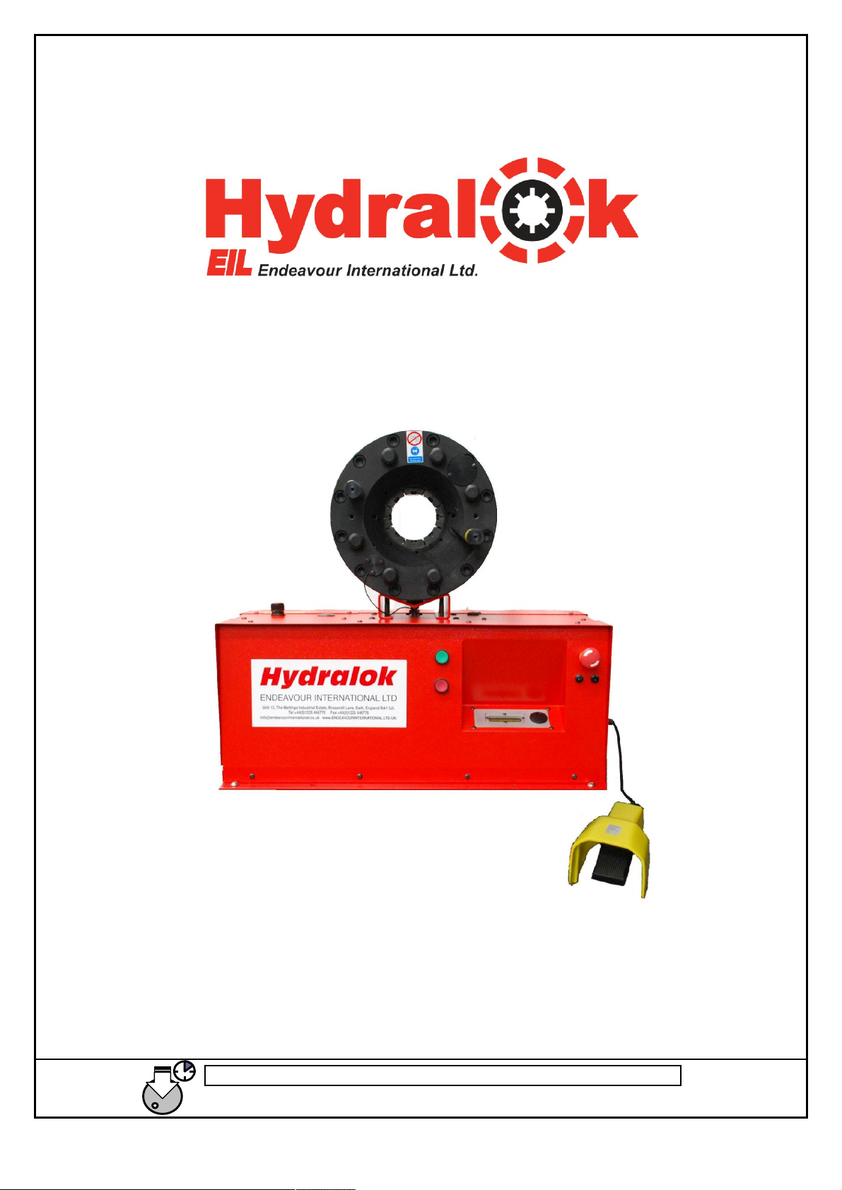
ENDEAVOUR Hydralok H25BE4, Hydralok H32BE4, Hydralok H50BE4, Hydralok H32CE4, Hydralok H50CE4 User Manual
...
ENDEAVOUR Int. Ltd. Tel +44 (0) 1225 446770 Fax +44 (0) 1225 446775
Long press Jog wheel to
go to
Main Menu at any time
www.endeavouri
nternational.ltd.uk
USER MANUAL
Types H25BE4,H32BE4,H32CE4
Swaging Machine
H50BE4, H50CE4, H50CE6
1

ENDEAVOUR Int. Ltd. Tel +44 (0) 1225 446770 Fax +44 (0) 1225 446775
Long press Jog wheel to
go to
Main Menu at any time
www.endeavouri
nternational.ltd.uk
Table Of Contents
Table Of Contents .........................................................................................................................2
WARRANTY CONDITIONS.......................................................................................................3
WARRANTY CONDITIONS.......................................................................................................4
EC DECLARATION OF CONFORMITY ....................................................................................5
SAFETY REGULATIONS ...........................................................................................................6
TECHNICAL / DIMENSIONAL DATA ......................................................................................7
HANDLING/TRANSPORT..........................................................................................................7
PRELIMINARY CHECKS ...........................................................................................................7
LIGHTING ...................................................................................................................................7
ROUTINE MAINTENANCE........................................................................................................8
INSTALLATION..........................................................................................................................8
Three Phase Machines:..............................................................................................................8
Single Phase Machines: .............................................................................................................8
Starting the machine for the first time:.......................................................................................8
SAFETY PRECAUTIONS............................................................................................................8
MANUAL SWAGING PROCEDURE (Machines without Quick Change)..................................10
MANUAL SWAGING PROCEDURE (Machines with Quick Change) ......................................11
QUICK CHANGE TOOL OPERATING INSTRUCTIONS *.....................................................12
Inserting dies into the machine ................................................................................................12
AUTO MODE *..........................................................................................................................13
Dwell*: ...................................................................................................................................13
Opening Time .........................................................................................................................13
Hose Counter*.........................................................................................................................14
Swage Offset...........................................................................................................................14
ADVANCED OPTIONS.............................................................................................................15
Preset Menu *..........................................................................................................................15
Save a Preset .......................................................................................................................15
Use a preset .........................................................................................................................16
Edit a preset.........................................................................................................................17
Delete a preset .....................................................................................................................17
SETUP MENU............................................................................................................................19
Die Table.................................................................................................................................19
Custom Die Sets ..................................................................................................................19
Lubrication..............................................................................................................................21
Quick Change (QC) Position Adjustment †..............................................................................23
Calibration Instructions ...........................................................................................................24
Display....................................................................................................................................26
Language.................................................................................................................................26
Reset to Factory Settings .........................................................................................................27
TECHNICAL INFORMATION..................................................................................................28
Maintenance And Service........................................................................................................28
Spare Parts ..............................................................................................................................28
Swaging Head Drawing (Fig 1) ...............................................................................................29
Die Chart.................................................................................................................................30
Die Fitting Instructions............................................................................................................31
Electrical Diagram: 3 Phase.....................................................................................................33
2

ENDEAVOUR Int. Ltd. Tel +44 (0) 1225 446770 Fax +44 (0) 1225 446775
Long press Jog wheel to
go to
Main Menu at any time
www.endeavouri
nternational.ltd.uk
Electrical Diagram: 1 Phase.....................................................................................................34
3

ENDEAVOUR Int. Ltd. Tel +44 (0) 1225 446770 Fax +44 (0) 1225 446775
Long press Jog wheel to
go to
Main Menu at any time
www.endeavouri
nternational.ltd.uk
WARRANTY CONDITIONS
Please note that all machines undergo strict testing before shipment.
1. All machines are warranted against any defects for a period of twelve (12) months starting
from the date of delivery to the customer.
2. Defective items/machines must be returned to our address with shipping charges pre-paid. We
will return items/machines with “carriage forward”. We are unable to accept items/machines
returned to us unless carriage charges have been paid.
3. This warranty covers the replacement and or repair of any component found to be defective
during the warranty period.
4. Replacements and repairs completed under this warranty do not extend the original twelve (12)
month warranty period.
5. This warranty does not cover normal wear under normal operating conditions
6. This warranty is not valid for damage resulting from incorrect operation, or use not in
compliance with the machine instructions.
7. This warranty is not valid in case of unauthorized machine modification.
4
ENDEAVOUR Int. Ltd. Tel +44 (0) 1225 446770 Fax +44 (0) 1225 446775
Long press Jog wheel to
go to
Main Menu at any time
www.endeavouri
nternational.ltd.uk
EC DECLARATION OF CONFORMITY
5

ENDEAVOUR Int. Ltd. Tel +44 (0) 1225 446770 Fax +44 (0) 1225 446775
Long press Jog wheel to
go to
Main Menu at any time
www.endeavouri
nternational.ltd.uk
SAFETY REGULATIONS
Always work in safe conditions and with the necessary space around the machine.
Ensure that the machine is placed on a stable and appropriate working surface.
1. DO NOT USE the equipment before reading the user manual.
2. CAUTION! If improperly used, the equipment may be dangerous and may cause
injury. Do not touch any moving parts.
3. CAUTION! It is absolutely essential that all working operations are carried out by
one operator only
4. This manual must be provided for the machine operator. Ensure that the operator
is aware of his/her responsibilities.
5. Guards must never be removed or tampered with.
6. (Where applicable) A fully trained and competent electrician must connect the
machine to the appropriate electricity supply.
7. Always wear protective gloves, safety glasses and appropriate clothing.
8. (Where applicable) Disconnect the power supply before removing any covers, or
attempting any maintenance of the machine
9. Only original spare parts can be used in the maintenance of the machine.
6
ENDEAVOUR Int. Ltd. Tel +44 (0) 1225 446770 Fax +44 (0) 1225 446775
Long press Jog wheel to
go to
Main Menu at any time
www.endeavouri
nternational.ltd.uk
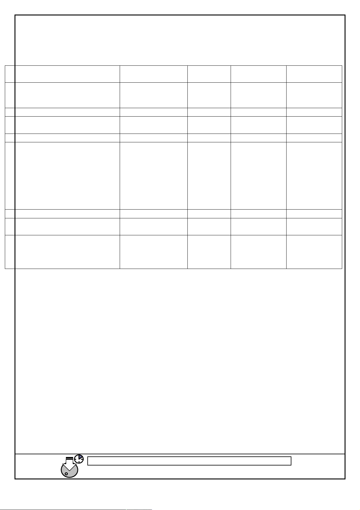
TECHNICAL / DIMENSIONAL DATA
TECHNICAL/DIMENSIONAL
DATA
Capacity 3/16”- 1” (4 wire)
Motor 2.2KW 2.2KW 2.2KW 2.2KW
Packed Dimensions in mm 900x600x900 940x640x10
Gross weight in Kg 130 130 175 300 Kg
Voltage (Current) 1 Phase
Swaging force 24 AC & DC 1750 Kn 2509 KN 4500 KN
Swaging range 6 mm – 45.9
Standard dies Not exceeding
H25BE4 H32BE4/
H32CE4
3/16”- 11/4”
R9R/4SP
220/240-150HZ (15) or
380/440-3-50HZ (5)
73dB(A)
(4 wire)
R9R/4SP
220/240-1-
220/240 -
380/440-3-
225/280 –
440/480 60
16 19 22 26
30 34 40 46
30
50HZ
50 Hz
Hz
mm
H50BE4/
H50CE4
3/16”- 2” (4
wire)
R9R/4SP
940x640x1030 800x1200x930
220/240-1-50HZ
or
220/240 -
380/440-3-50
Hz 225/280 –
440/480 60 Hz
0.6 mm – 76
mm
16 19 22 26 30
34
40 46 52 58 64
70
H50C6
3/16”- 2” (6
wire)
220/240-1-50HZ
or
220/240 -
380/440-3-50
Hz 225/280 –
440/480 60 Hz
0.6 mm – 82
mm
16 19 22 26 30
34 40 46 52 58
64 70 76
HANDLING/TRANSPORT
The machine will normally be shipped bolted to a wooden pallet . The bolts should be removed
and the machine lifted onto the work place using suitable lifting equipment.
PRELIMINARY CHECKS
Place the machine on a flat and stable base.
Where applicable, ensure that the power supply line is fitted with a differential safety breaker and
overload cut-out.
LIGHTING
The equipment does not have its own lighting and so it must be used in a suitably illuminated area.
7
ENDEAVOUR Int. Ltd. Tel +44 (0) 1225 446770 Fax +44 (0) 1225 446775
Long press Jog wheel to
go to
Main Menu at any time
www.endeavouri
nternational.ltd.uk
ROUTINE MAINTENANCE
Ensure that moving parts are always lightly greased. Where applicable check periodically that the
limit switches and emergency controls are in good working order.
At the top of the machine base, remove the oil filler cap and check that the oil level correct. Where
necessary add oil (ISO 32 Hydraulic oil).
INSTALLATION
The machine must be bolted to a firm workbench in a horizontal position. If a quick change rack is
supplied, the machine must be bolted to it with the bolts supplied. The machine is top heavy,
therefore ensure that it is stable and does not pose a danger for the user or other people.
Three Phase Machines:
When operating the machine for the first time check that the motor rotation direction is correct.
(Three phase machines only) If the motor starts but jaws of the swaging head do not begin to close
when the green button is pressed to swage, the phase rotation of the motor will have to be
reversed. To reverse the rotation of the motor change over any two of the phase cables in the
machine’s plug. A competent electrician should carry out the rewiring of the electric plug.
Single Phase Machines:
Ensure that the power loop is for industrial use, rated for at least 20Amps. Install the machine as
close to the socket as possible. Do not use long extension leads as this increases the current
demand from the machine. Do not connect to residential rated 13Amps loops.
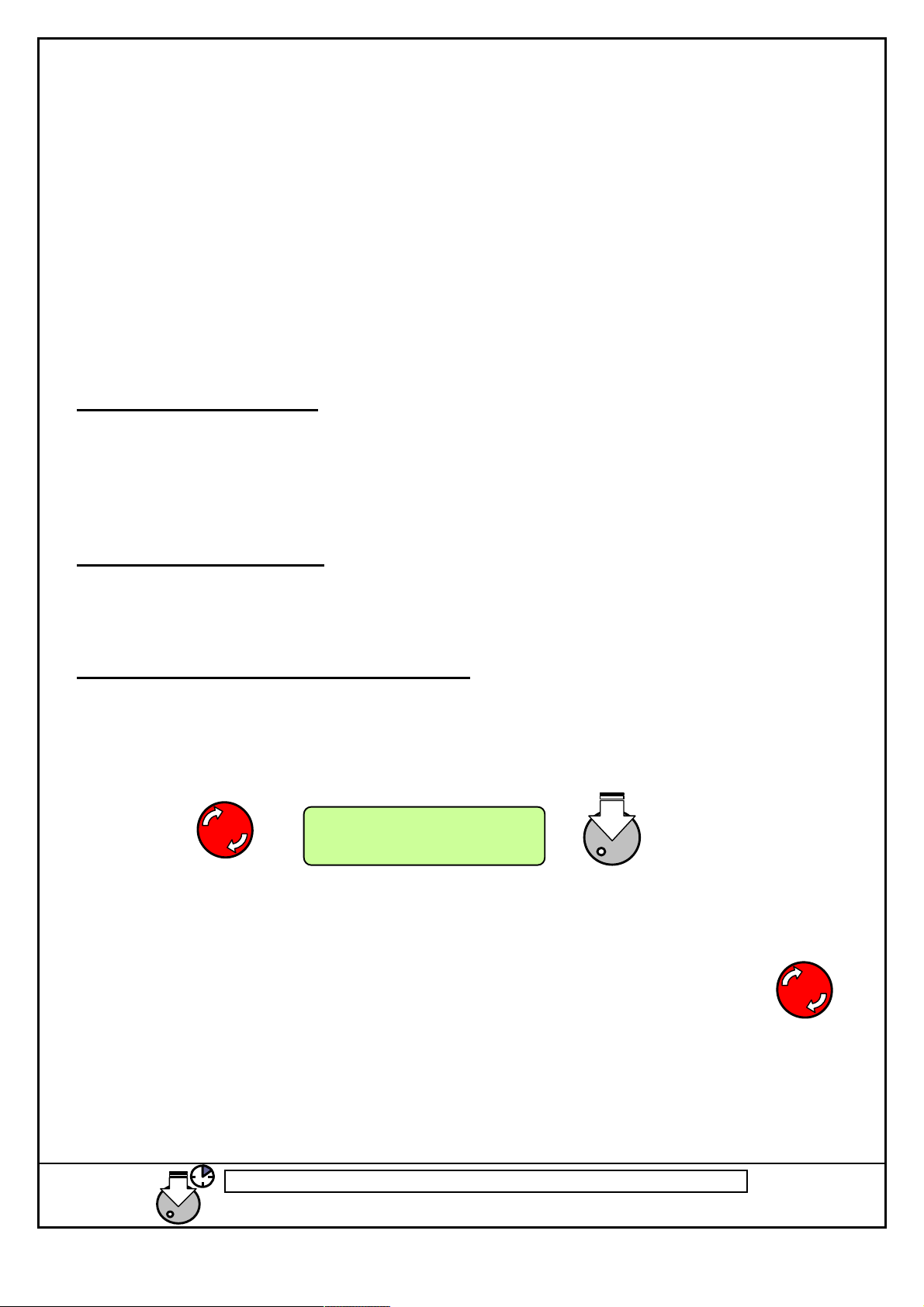
Starting the machine for the first time:
After the machine is connected to the power supply, if the Emergency Stop is pressed, rotate it to
disengage. The LCD screen will still show the E-Stop message. This is a safety measure to avoid
starting the machine by accident. Press the jog wheel once to acknowledge the message and start
the machine..
Emergency Stop
Restart ()
SAFETY PRECAUTIONS
Switch off machine when not in use, using the latching emergency stop button To unlatch the stop
button twist the red knob clockwise and release.
To stop the machine in an emergency press the RED EMERGENCY STOP BUTTON.
DO NOT START THE MACHINE UNDER LOAD.
ALWAYS RELEASE PRESSURE BEFORE RESTARTING.
ISOLATE THE MACHINE FROM THE ELECTRICAL SUPPLY WHEN NOT IN USE.
8

ENDEAVOUR Int. Ltd. Tel +44 (0) 1225 446770 Fax +44 (0) 1225 446775
Long press Jog wheel to
go to
Main Menu at any time
www.endeavouri
nternational.ltd.uk
9
ENDEAVOUR Int. Ltd. Tel +44 (0) 1225 446770 Fax +44 (0) 1225 446775
Long press Jog wheel to
go to
Main Menu at any time
www.endeavouri
nternational.ltd.uk
L16
BUZZ
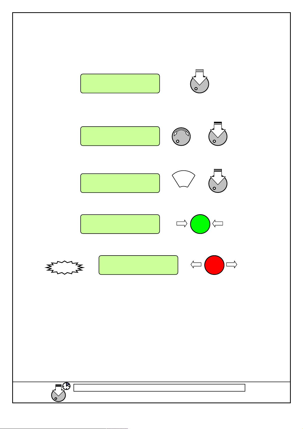
MANUAL SWAGING PROCEDURE (Machines without Quick Change)
From the main menu, press the jog wheel once to access the diameter selection option.
Main Menu
Set Diameter
Rotate the jog wheel to select the swage size. Clockwise to increase / anticlockwise to decrease
size. Once the size is selected, press jog wheel to confirm.
Push to Confirm
17.90mm
Manually fit the dies as shown on screen and press Jog wheel to confirm.
Fit Die L16
Manual OK(↓)
Place the hose in position and press green button to swage to selected size
Swage to 17.90mm
Menu() --.--mm
Buzzer will sound and machine will stop when size is reached. Press Red Button to open.
Swage to 17.90mm
Menu() 17.90mm
10
ENDEAVOUR Int. Ltd. Tel +44 (0) 1225 446770 Fax +44 (0) 1225 446775
Long press Jog wheel to
go to
Main Menu at any time
www.endeavouri
nternational.ltd.uk
L16
BUZZ
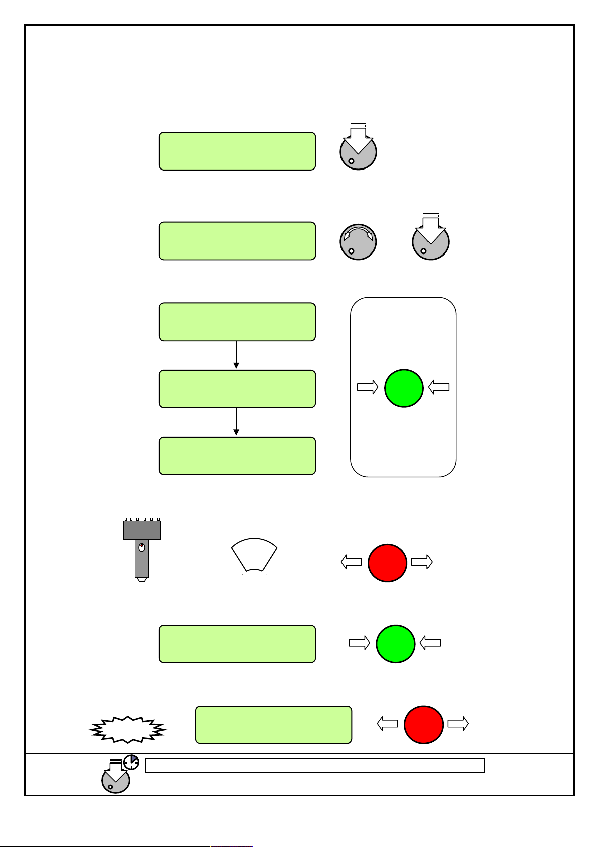
MANUAL SWAGING PROCEDURE (Machines with Quick Change)
From the main menu, press the jog wheel to access the diameter selection option.
Main Menu
Set Diameter
Rotate the jog wheel to select the swage size. Clockwise to increase / anticlockwise to decrease
size. Once the size is selected, press jog wheel to confirm.
Push to Confirm
17.90mm
Press and hold green button to go to Quick Change Position
Fit Die L16
Q/C(Grn) OK(↓)
Fit Die L16
Hold Green Btn
Fit Die L16
Red When Fitted
Fit the dies using quick change tool, remove tool and press red button to open machine.
Place the hose in position and press green button to swage to selected size
Swage to 17.90mm
Menu() --.--mm
Buzzer will sound and machine will stop when size is reached. Press Red Button to open.
Swage to 17.90mm
Menu() 17.90mm
11
 Loading...