

ENDEAVOUR E40, 40 Owner's Manual
ENDEAVOUR 40 OWNERS MANUAL

ENDEAVOUR 40 OWNERS MANUAL
Table of Contents
1. Introduction
2. List of Figures
3. Construction
3.1 Hull
3.2 Deck
3.3 Deck/Hull Joint
3.4 Rudder and Steering
3.5 Ballast
3.6 Interior Construction
4. Spars and Rigging
4.1 Spars
4.2 Standing Rigging, Running Rigging, Chainplates
4.3 Static Tuning (at the Dock)
4.4 Dynamic Tuning (under Sail)
5. Fuel System
5.1 Fuel Tank
5.2 Fueling
6. Engine and Transmission of Power
6.1 Engine
6.2 Transmissions
6.3 Propeller Shaft and Stuffing Box
6.4 Shaft Alignment
6.5 Propellers
6.6 Removal of Propellers
6.7 Installation of Propellers
6.8 Propeller Alignment
6.9 Exhaust System
7. Engine Controls
7.1 Description
7.2 Starting the Engine
7.3 Stopping the Engine
8. Electrical System
8.1 General
8.2 Direct Current (D.C.) System
8.3 Battery Maintenance
8.4 Alternating Current (A.C.) System
8.5 A.C. Shore Power
8.6 A.C. Ship’s Power (Auxiliary Generator)
8.7 Generator Diesel
2

9. Plumbing System
9.1 Head and Holding Tank
9.2 Galley Stove Operation
10. Maintenance
10.1 Gelcoat Surfaces
10.2 Ports and Hatches
10.3 Teak
10.4 Hull Bottom
10.5 Standing Rigging
10.6 Running Rigging
10.7 Lifelines, Pulpits, Stanchions
10.8 Winches and Block
10.9 Engine
10.10 Power Train
10.11 Electrical Maintenance
10.12 Upholstery
10.13 Steering
11. Fitting Out
11.1 Prior to Launching
11.2 After Launching
11.3 Stepping the Spar
12. Laying Up for Winter Storage
12.1 Hauling (Slings)
12.2 Cradle Support
12.3 After Haul Out
12.4 Fresh Water. System
12.5 Head and Holding Tank
12.6 Batteries
2. LIST OF FIGURES
Figure Title Page
1 Deck-to-Hull Joint 4
1A Topside Deck Layout 4
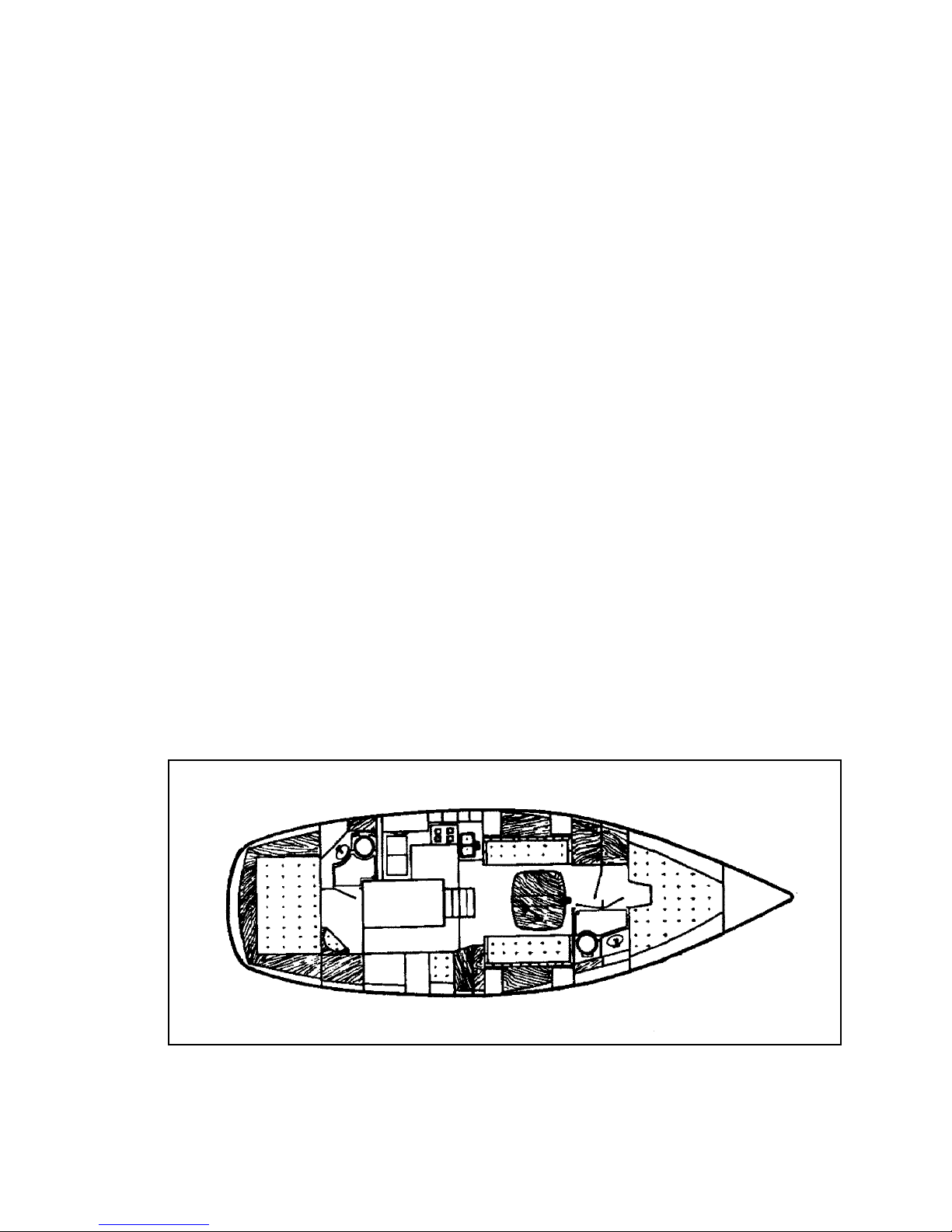
1B Interior Deck Layout 5
2 Chainplate Installation 6
3 Reefing System 8
4 Deck Wiring 15
5 Head System Description 15
6 Plumbing System Description 16
7 LPG System 16
8 Alcohol Stove System 17
9 Lift Strap Locations 21
10 AC/DC Electrical Panel Wiring Diagram (no generator) not avail.
11 DC Panel Wiring Diagram (generator option) not avail.
12 AC Panel Wiring Diagram (generator option) not avail.
13 Cockpit Instrument Panel Wiring 12
3

3. CONSTRUCTION
3.1) Hull:
The hull is molded as a single unit of a combination of polyester resin and fiberglass woven roving and
multi-directional chopped strand fiber (MCSF). The keel is molded integrally with the hull and all
ballast is contained inside. The exterior finish is a pigmented gelcoat molded onto the fiberglass. The
boot and sheer stripe are also gelcoat molded permanently into the hull.
3.2) Deck:
The deck and cockpit, like the hull, are molded as a single unit of a combination of polyester resin and
fiberglass woven roving and MCSF. Plywood coring is incorporated between layers of fiberglass in the
cabin top, deck, seat, and cockpit sole areas to give additional stiffness. The non-skid finish is molded
into the deck. All exterior deck surfaces are a pigmented gelcoat molded onto the fiberglass.
3.3) Deck/Hull Joint:
The joint between the hull and deck is one of the
most important assembly steps in the construction of
a yacht. The method used by Endeavour Yacht is
simple, strong, and reliable. Figure #1 illustrates
details of this assembly.
During assembly, the top of the integral hull flange is
liberally coated with a combination adhesive/sealant.
The deck is then lowered onto the hull and fastened
in place with stainless steel bolts. When the bolts are
tightened, the excess compound is forced into all
crevices and out the sides. The teak cap is then
installed, bedded in a heavy layer of the same
compound and secured in place, doubly ensuring
water tightness.
3.4) Rudder and Steering:
The rudder is molded as a single piece of solid high
density foam with a protective skin of fiberglass and
a gelcoat finish. The foam material is of high
strength structural grade and has exceptional
toughness. The rudder post, molded integrally inside
4
rudder, is solid stainless steel, which is welded to a steel blade in the interior of the rudder.
Where the rudder post passes through the hull, water tightness is ensured by means of a stuffing box. It
is recommended that the packing inside the stuffing box be replaced annually to ensure continued
water tightness. Packing of the proper size is available from most marine hardware stores. The
Endeavour 40 requires 3/8” square packing. Cut packing in individual rings rather than a long spiral to
prevent binding on the rotating shaft.
The pedestal steering system installed on your yacht operates with stainless steel cables rotating a
quadrant bolted and keyed to the rudder post. The cables run through a conduit attached to a massive
steel support frame at the rudder and the motor mount then to the pedestal where they are shackled to a
stainless steel chain running over a sprocket on the steering sheel shaft. Normal maintenance should
only require occasional oiling of all the moving parts with teflon grease, inspection of cables for wear
and proper tension, and a check of all bolted connections for tightness.
3.5) Ballast:
All ballast is internally mounted inside the keel, which is molded integrally with the hull. Cast pieces
of lead are placed in the hull, encapsulated in a polyester bonding resin, and then covered with a layer
of woven roving to form a fiberglass cap. When finished, the ballast becomes a structural part of the
hull.
3.6) Interior Construction:
The interior of your Endeavour 40 is built up of wood. First, a framework of floor timbers is
constructed and placed in the bilge and heavily bonded in place with woven roving. A plywood sole is
glued and screwed on top of these floor timbers and bonded to the hull all around its periphery with
woven roving.
All timbers and plywood are saturated with polyester resin before assembly to seal all exposed wood.
Next, the entire sole is covered with teak parquet flooring, bonded in place with a waterproof adhesive.
All bulkheads are bonded to the hull with two layers of woven roving on both sides.
5
4. SPARS AND RIGGING
4.1) Spars:
All spars (masts, booms, and spreaders) are extruded aluminum 6061-T6 alloy with a protective
coating on all external surfaces. The main mast of the E-43 is stepped through the cabin roof onto the
keel. The mizzen mast is stepped on deck with a supporting post or structure immediately under the
mast.
4.2) Standing Rigging, Running Rigging, Chainplates:
Standing rigging refers to all the fixed pieces of
stainless steel wire which support the mast. If
they principally support the spar in a fore and
aft direction, they are called “stays” (backstay,
forestay, etc.). If they support mainly from side
to side, they are called “shrouds” (upper
shroud, etc.).
The forestay attaches to the stem head fitting at
the bow. This is fabricated of welded stainless
steel and through bolted to the hull with backup plates. All other stays and shrouds are
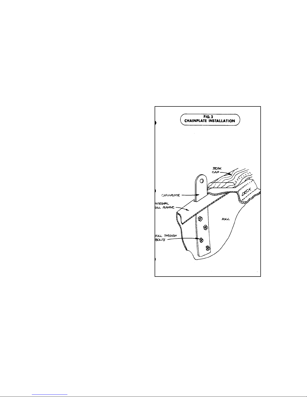
attached to chainplates at the edge of the deck.
These chainplates are stainless steel straps
through bolted to the hull. Additional fiberglass
reinforcement is molded into the hull in all
chainplate areas. See Figure #2 for a
description of this installation.
All standing rigging is attached to chainplates
with adjustable turnbuckles that allow fine
tuning of rigging tension.
Running rigging includes all working lines or
cables that normally require adjustment when
sailing. Examples of these include halyards,
sheets, reefing gear, outhauls, etc.
All halyards are stainless steel wire rope spliced
to dacron line tails to minimize stretch, reduce
windage aloft, and maximize service life. All
halyards are run externally to the mast to
facilitate inspection, repair, or replacement.
4.3) Static Tuning (At the Dock)
First, make certain that the mast is centered on the boat, straight up and down when viewed from the
bow or stern. To make certain the mast is plumb transversely, slacken the lower shrouds fully by
undoing their turnbuckles. Make sure the mast wedges are removed from the main mast, which is
stepped through the deck. Take the main halyard and lead the shackle end to a point at the deck edge
so the shackle just touches the chainplate or rail with a given tension. Tie off the halyard. Take the
halyard to the same location on the other side and with the same tension the shackle should just touch
the rail or chainplate. If not, let off one upper shroud’s turnbuckle and take up on the other to bring the
masthead closer to centerline until the halyard shackle touches both points under the same tension. The
6

particular part of the rail or deck you choose as your reference point is not important as long as it is the
same point on each side After the mast is centered transversely, tighten both upper shroud turnbuckles
uniformly, one full turn on one side, then one full turn of the other. Repeat until the turnbuckles
become difficult to turn. Pin the turnbuckles Tighten up the lower shroud turnbuckle so that almost all
of the slack is removed. That is, the shroud itself should be able to flop about 1” in each direction.
Sight up the trailing edge of the spar to make sure that it is still straight. Now, check your rake. With
the main halyard hanging plumb behind the mast, the shackle end should be about one mast width
away from the back face of the mast, near the gooseneck. It’s best to do this on a calm day and to hang
a weight on the halyard such as a hammer, wrench, or bucket of water.
Ease off the forestay or backstay as required and tighten the other to adjust the rake. Large adjustments
may also necessitate tightening and loosening of the forward and aft lower shrouds. Once proper rake
is established, further adjustment should not be necessary of either the forestay or backstay. Tighten
the turn-buckles to obtain proper tension and pin.
Reinstall the mast wedges and trim collar on the main mast.
Check that the spreaders are angled upward slightly to equalize the angles above and below between
the spreader and the shroud. Tape and pad the spreader ends to avoid wear and tear on sails.
4.4) Dynamic Tuning (Under Sail)
Select a pleasant day with a steady 8 to 12 knots of breeze. Put the boat on a starboard tack, close
hauled Sight up the luff groove of the spar. If the mast seems to fall off to leeward at the spreaders, luff
up slightly and tighten the starboard lower shrouds a couple of turns. Put the boat back on the wind and
check the spar again. When the mast appears straight, put the boat about and do the same on the port
side. Check the following carefully. First, if the upper shrouds are at optimum tension, then the
leeward rigging should begin to look slack when at about l5
leeward shrouds should never be tightened. Secondly, when close hauled under genoa and main, the
forestay will appear quite sagged. Tensioning the backstay will reduce the amount of sag, but the sag
itself can never be completely eliminated.
0
-200 of heel. This is quite natural and the
The forward lower shrouds should be tightened marginally more than the aft lowers to encourage a bit
of a forward bow to the mast. This forward bow is counteracted by the luff of the mainsail and the aft
lowers. Aft bow of the mast should not be allowed, it destroys the sail shape and is countered only by
the forward lower shrouds. If you find that the mast tends to bow aft rather than forward under
backstay tension, the problem may then lie in your mast step. For example, if the mast is resting on its
forward end, it may tend to bow aft. Therefore, to correct this situation, wedge up the after part of the
heel to encourage a forward bow.
If yours is a brand new boat, chainplates may seat and the rigging may stretch to the extent that tuning
from scratch will be necessary in a matter of weeks. This is expected and typical of any new boat.
However, after this initial working-in period, you will find that your boat tends to hold this tune for
fairly long periods of time. After becoming used to the feel of the boat, you may wish to either increase
or decrease the amount of “weather helm” - that is, the amount of feel on the wheel. Any sailboat when
going upwind should have a tendency to “round up” slightly or head into the wind if you let go of the
helm. However, if you’re constantly fighting the boat in order to hold her off the wind, you have too
much weather helm. This can be alleviated by taking some rake out of the spar; i.e., raking the spar
further forward, and thus moving the center of effort of the sailplan further forward. If you find when
sailing upwind that the boat tends to fall off the wind and you are constantly having to push her to
weather, then you probably have lee helm. This can be overcome by putting a bit more rake into the
spar.
With constant tuning as the season progresses, your boat performance will improve. The boat will feel
more comfortable to sail. You will find that tuning is a bit of an art; you’ll begin to notice subtle
changes in the behaviour and response of your boat as you make subtle changes in tuning. The
important thing to remember is to go about things in a slow and orderly fashion, and before you make
any change, make sure it makes sense in your own mind.
7
 Loading...