

ENDAT 4066i, ENDAT-4066i User Manual

User’s Manual I
END AT-4066i
User’s Manual
Rev. 1A
4066i PCB ver: A2 or later
25/05/2007
II
The ENDAT-4066i System Board
Copyright Notice
The content of this manual has been checked for accuracy. The manufacturer
assumes no responsibility for any inaccuracies that may be contained in this
manual. The manufacturer reserves the right to make improvements or
modification to this document and/or the product at any time without prior
notice. No part of this document may be reproduced, transmitted, photocopied or
translated into any language, in any form or by any means, electronic, mechanical,
magnetic, optical or chemical, without the prior written permission of the
manufacturer.
Intel® Pentium4®, Celeron® and Celeron D ® is registered trademark of Intel
Incorporation
Multiscan is a trademark of Sony Corp of America
IBM, EGA, VGA, PC/XT, PC/AT, OS/2 and PS/2 are registered trademarks of
International Business Machines Corporation
Plug and Play is registered trademarks of Intel Corporation
Microsoft, Windows and MS-DOS are trademarks of Microsoft Corporation
Award is a trademark of Phoenix Software Inc.
PCI is a registered trademark of PCI Special Interest Group
Other product names ment ioned herei n are used for identification purpose only and
may be trademarks and/or registered trademarks of their respective companies.
Installation Notice
The manufacturer recommends using a grounded plug to ensure proper
motherboard operation. Care should be used in proper conjunction with a
grounded power recept acle to avoid p ossible electr ical shock. All integrated circ uits
on this motherboard are sensitive to static electricity. To avoid damaging
components from electros tatic disch arge, please do not remove the b oard from the
anti-static pack ing bef ore disc hargi ng any st atic e lectrici ty to y our body, by wearing
a wrist-grounding strap. The manufacturer is not responsible for any damage to the
motherboard due to improper operation.
User’s Manual III
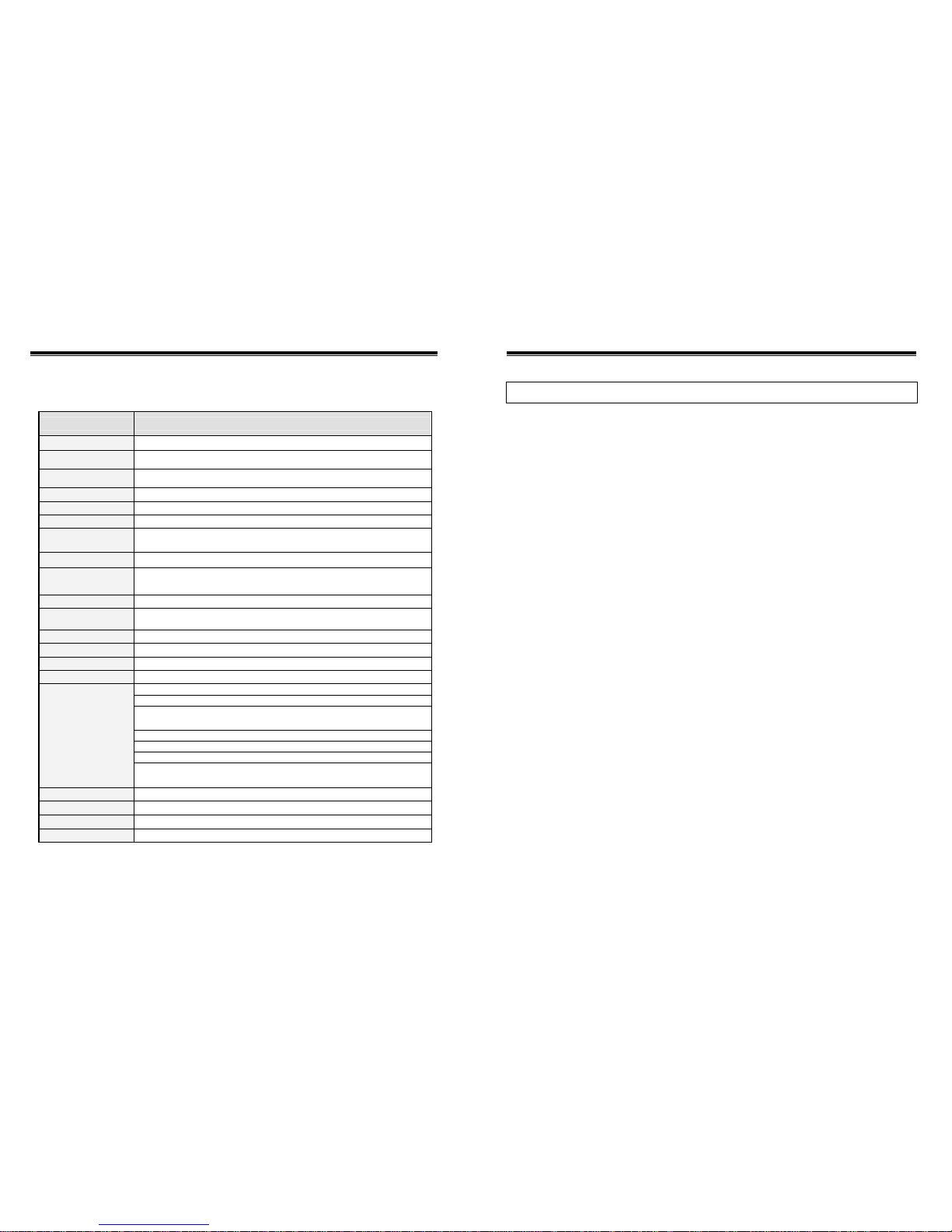
Specification:
Model ENDAT-4066i
Form Factor
Mini-ITX 170 mm x 170 mm (6.69”x6.69”)
System Chipset
INTEL 865GV + ICH5
CPU Supporting
533/400 FSB with 478 pin PENTIUM4/Celeron/Celeron D processor
Memory
1 x 184 pin DDR socket support DDR 400/333/266 up to 1GB
Ethernet
INTEL 82801ER/EB (ICH5) + PHY (Intel 82562EX)
VGA
INTEL 865GV Graphic Controller with DVMT up to 96MB(max)
LCD interface
Onboard LVDS support 18/24/36/48bit Single/Dual Channels via internal
box header (optional)
Display ratio
4:3 and 16:9
Serial / Parallel
2 Serial Port w/+5V, +12V Power Selector / 1 Parallel port (Optional to 6
Serial ports via I/O kit)
Watchdog Timer
Winbond 83627THG on-chip support 1 to 255 seconds/minutes
IDE Connector
1 x 40pin IDE connector support UDMA 33/66/100
1 x 44pin IDE connector support Slim type HDD
SATA Connector
Support 1 port 150MHz Serial ATA Device
AUDIO
On-board support AC'97 with 1.2W amplifier
CMOS backup
EEPROM backup customized setting in system BIOS
Expansion Slot
One PCI expansion up to 3 PCI slots via riser card with PCI 2.2 compliance
PS/2 Keyboard / Mouse Connector
2 x USB (2.0) + RJ-45 Connector w/LED indicator
D-sub Connector for COM 1,2 (internal box header for COM2) with
POWER
1 x 25 Pins D-Sub Connector (LPT)
1 D-Sub Connector (VGA)
MIC-IN, Line-In, SPK-Out with COM2 Module Deck
I/O Port
Internal pin header: KB, MS, USB (2.0) x4, AUX/CD-IN, SPDIF IN/OUT, RF
MIC IN, IR
Digital IO
2 bit input and 2 bit output (TTL level) by pin header
RS-422/485
Via COM2 (Optional)
USB Port
6 x USB2.0 onboard
Power Supply
Support P4-ATX power supply
IV The ENDAT-4066i System Board
TABLE OF CONTENTS
CHAPTER 1. INTRODUCTION .......................................................1
1-1. FEATURES ......................................................................................... .....2
1-2. UNPACKING ..... .................................................................................. ..... 3
1-3. ELECTROSTA TIC DI SCHARGE PRECAUTIONS ................................... 3
1-4. MOTHERBOARD LAYOUT.......................................... ............................ 4
CHAPTER 2. SETTING UP THE MOTHERBOARD.......................5
2-1. JUMPERS AND CONNECTORS.............................................................. 5
2-2. INSTALLING MEMORY............ .............................................................. 14
2-3. SHARED VGA MEMORY....................................................................... 14
2-4. INSTALLING RISER CARD.................................................................... 14
2-5. ASSIGNING IRQs FOR EXPANSION CARDS....................................... 14
2-6. WATCHDOG TIMER…………………………………………………………. 15
2-7. DIGITAL I/O…………………………………………………………...………. 17
CHAPTER 3. AWARD BIOS SETUP.............................................18
3-1. STANDARD CMOS FEATURES............................................................. 19
3-2. ADVANCED BIOS FEATURES............................................................... 20
3-3. ADVANCED CHIPSET FEATURES ........................................................ 21
3-4. INTEGRATED PERIPHERALS............................................................... 23
3-5. POWER MANAGEMENT SETUP........................................................... 27
3-6. PnP/PCI CONFIGURATIONS................................ ................................. 28
3-7. PC HEALTH STATUS............................................................................. 29
3-8. FREQUENCY/VOLTAGE CONTROL ..................................................... 29

User’s Manual V
CHPATER 4. VGA, LCD, FEATURE..............................................31
4-1. VGA FEATURE....................................................................................... 31
4-2. LVDS PANEL AND TV FEATURE........................................................... 32
4-3. PCI BUS AUDIO ADAPTER FEA TURES................................................ 33
4-4. DRIVER UTILITY INSTALLATION GUIDE ............................................. 34
CHPATER 5. LAN ADAPTER........................................................35
5-1. FEATURES ...................... ...................................................................... 35
5-2. UTP CABLE/RJ-45 JACK DEFINITION.................................................. 36
5-3. CONNECTING 100BASE-TX FAST ETHERNET NETWORK................ 37
5-4. CONNECTING 10BASE-T ETHERNET NETWORK .............................. 37
5-5. 10MBASE/ 100MBASE INSTALLATION NOTICE .................................. 37
5-6. REMOTE BOOT ROM FUNCTION ........................................................ 38
5-7. LED INDICATORS.................................................................................. 38
APPENDIX A: FLASH MEMORY UTILITY....................................39
APPENDIX B: CONNECTOR PIN ASSIGNMENT........................ 40
APPENDIX C: UC-COM56 JUMPER SETTING............................41
APPENDIX D: LIMITED WARRANTY...........................................42

User’s Manual 1
Chapter 1. Introduction
ENDAT-4066i supports high performance processor of Intel® Pentium4®,
Celeron® and Celeron D ® with 400 and 533 Front Side Bus. It also supports high
speed DDR memory with 64-bit wide interfaces with non-ECC DIMM (up to 1GB).
Only Double Data Rate (DDR) SDRAM memory is supported and the speed of
memory can be 266, 333 and 400 MHz.
ENDAT-4066i provides an integrated graphics (Intel® Extreme Graphics 2)
accelerator delivering cost competitive 3D, 2D, and video capabilities.
ENDAT-4066i video engines support video conferencing and other video
applications. Instead of a dedicated local graphics memory interface, ENDAT-4066i
uses a UMA configuration for optimal memory utilization and performance that
deliver 3D graphics with s harp images, fast rendering, smooth motion and extreme
detail.
ENDAT-4066i contains one integrated Serial ATA host controllers capable of
independent DMA operation on two ports. The SATA controllers are complete ly
software transparent with the IDE interface, while providing a lower pin count and
higher performance. The data tr ansfer rate is up to 150 MB/s.
ENDAT-4066i is an ideal model for various kind of application:
- POS system
- KIOSK
- Interactive system
- Airport Terminal Controller
- Industrial controller
- Digital entertainment
- Embedded system equipment
2
The ENDAT-4066i System Board
1-1. Features
Basic Feature:
z Board format: Mini-ITX (170mm x 170 mm)
z Supports Socket 478 CPU (FSB 533/400 MHz)
z Digital I/O: 2 bits in and 2 bits out (3.3V)
z Supports DDR 266/ 333/ 400 SDRAM up to 1GB
z Serial ATA connector x 1
z Enhance IDE connector x 2
z Multiple I/O ports: COM port x 2; USB (2.0) x 6
z All COM ports with +5V, +12V power selector
z CMOS backup: EEPROM backup
z Watchdog Timer
z Intel 10/100 LAN and Audio function onboard
z With Intel embedded ATX PCI expansion design
Optional features:
z On board chip provides LVDS interface (18/24/36/48 bit, single/dual
channels) or TV out signals (composite and S-video)
z Second I/O kit for extra 4 COM ports (COM3 to COM6)
z RS 422/485 via COM 2
z Barebones system: niche into Unicorn U-8000 Chassis
Full Software Support:
z Drivers for major operating systems and APIs: Windows 9x / ME,
Windows 2000, Windows XP, Direct3D, DirectDraw and DirectShow,
OpenGL ICD for Windows 9x, and 2000, and DXVA for Windows
2000 and Windows XP

User’s Manual 3
1-2. Unpacking
The motherboard comes securel y packaged in a sturdy cardboard shippin g carton.
In addition to the User's Manual, the motherboard package includes the following
items:
ENDAT-4066i System Board
HDD / IO Cables
LCD cable (Optional)
CDROM Driver includes : Driv ers f or Wind ows 9 8, ME, 2000 , XP an d AMI / AWARD
FLASH ROM utilities.
Driver utilities for on-board VGA drivers, LAN adapter
If any of these items are missing or damage, please contact the dealer from whom
you purchase the moth er boar d. S av e t he s hipp in g m at erial a nd c a rt on i n t he e ve nt
that you want to ship or store the board in the future.
Note:
Please leave the motherboard in its original package until you are
ready to install it!
1-3. Electrostatic Discharge Precautions
Make sure you properly ground yourself before handling the motherboard, or other
system components. Electrostatic discharge can easily damage the components.
Note: You must take special precaution when handling the motherboard in dry or
air-conditioned environments.
4 The ENDAT-4066i System Board
1-4. Motherboard Layout
User’s Manual 5
Chapter 2. Setting up the Motherboard
2-1. Jumpers And Connectors
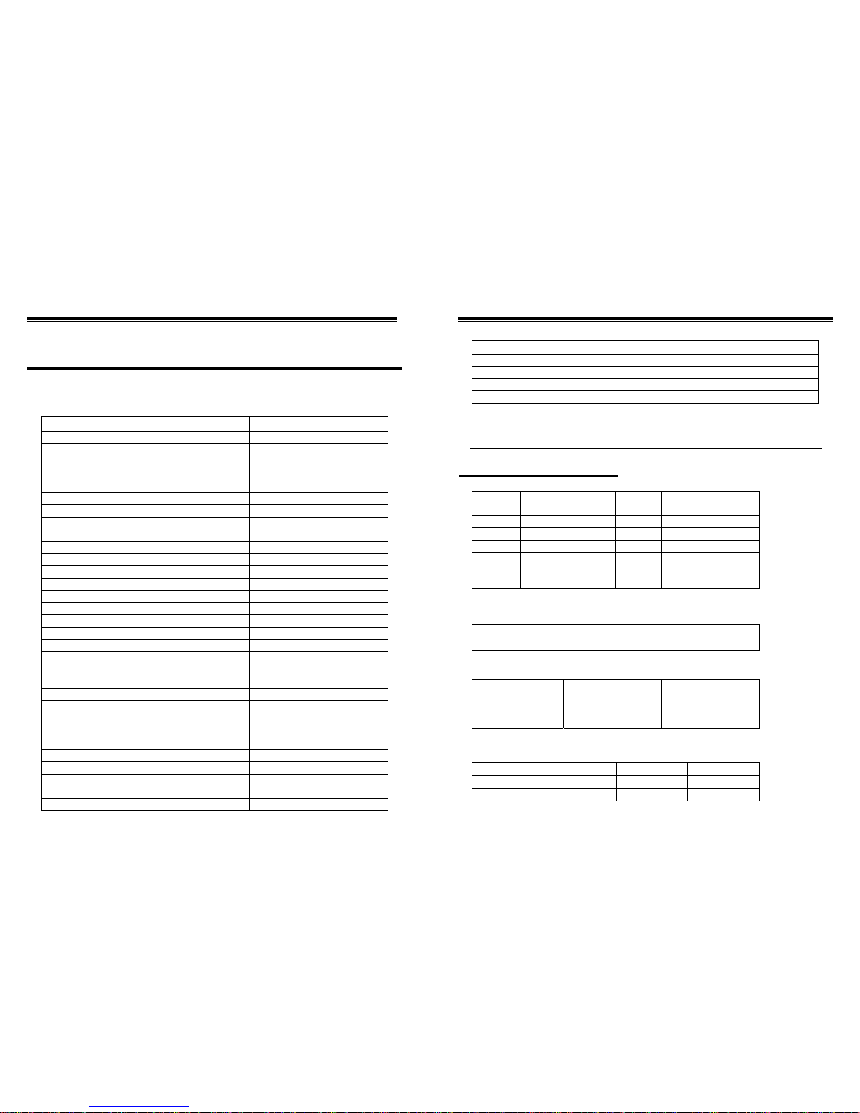
Jumpers/Connectors Overview:
Function Jumpers/Connectors
Cooling Fan Connector FAN1, FAN2
P4 Power Supply Connector 2*2 CN2
P4 Power Supply Connector 2*10 ATXPWR
LCD Panel Connector LVDS1
LCD Voltage Selector JP6
Clear CMOS JBAT1
Pin Header for external device JP1
PS/2 Mouse/KB Pin Header J1
PS/2 Mouse/KB CN1
USB Port CN3, J3, J4
IDE 1, IDE 2 IDE1, IDE2
SATA 1 SATA1
IDE active LED J9: Pin 1(-), Pin 2(+)
External Speaker J9: Pin 3, Pin 6
Buzzer On/Off J9: Pin 4, Pin 5
Hardware Reset Switch J9: Pin 7, Pin 8
Power LED J9: Pin 9(+), Pin 10(-)
ATX Power Supply On/Off Switch J9: Pin 11, Pin 12
WDT Function Enable/Disa ble J9: Pin 13, Pin 14
SATA LED J9: Pin 15(+), Pin 16(-)
DDR SDRAM socket DIMM1
LAN Connector CN3
CRT Output CN6
Power Good Selector JP2
COM1 & COM2 Voltage Select or JP4
COM1 CN4
COM2 CN8D1
LPT1 CN5
MIC In, Line In, Line Out CN7
COM2 Pin Header J2
RS232 / 485 Selector for COM2 JP3 & JP5
6 The ENDAT-4066i System Board
Function Jumpers/Connectors
DIGITAL I/O Pin Header J5
CD In & Line Out Pin Header J6
Microphone IN & LINE IN Pin Header J7
LPC Super I/O Connector J8
Please double-check the insertion and orientation of the LCD cable
before applying power. Improper installation will result in permanent
damage LCD panel.
Part 1: Onboard Jumpers
JP1: Pin Header for external device (2.0mm)
Pin No. Signal (MS) Pin No. Signal (KB)
1
MS Data Out
2
KB Data Out
3
MS Data In
4
KB Data In
5
MS Data Out
6
KB CK Out
7
MS CK In
8
KB CK In
9
KEY
10
KEY
11
+5V(DC)
12
+5V(DC)
13
GND
14
GND
Default setting is: 1-3, 5-7, 2-4 and 6-8 closes
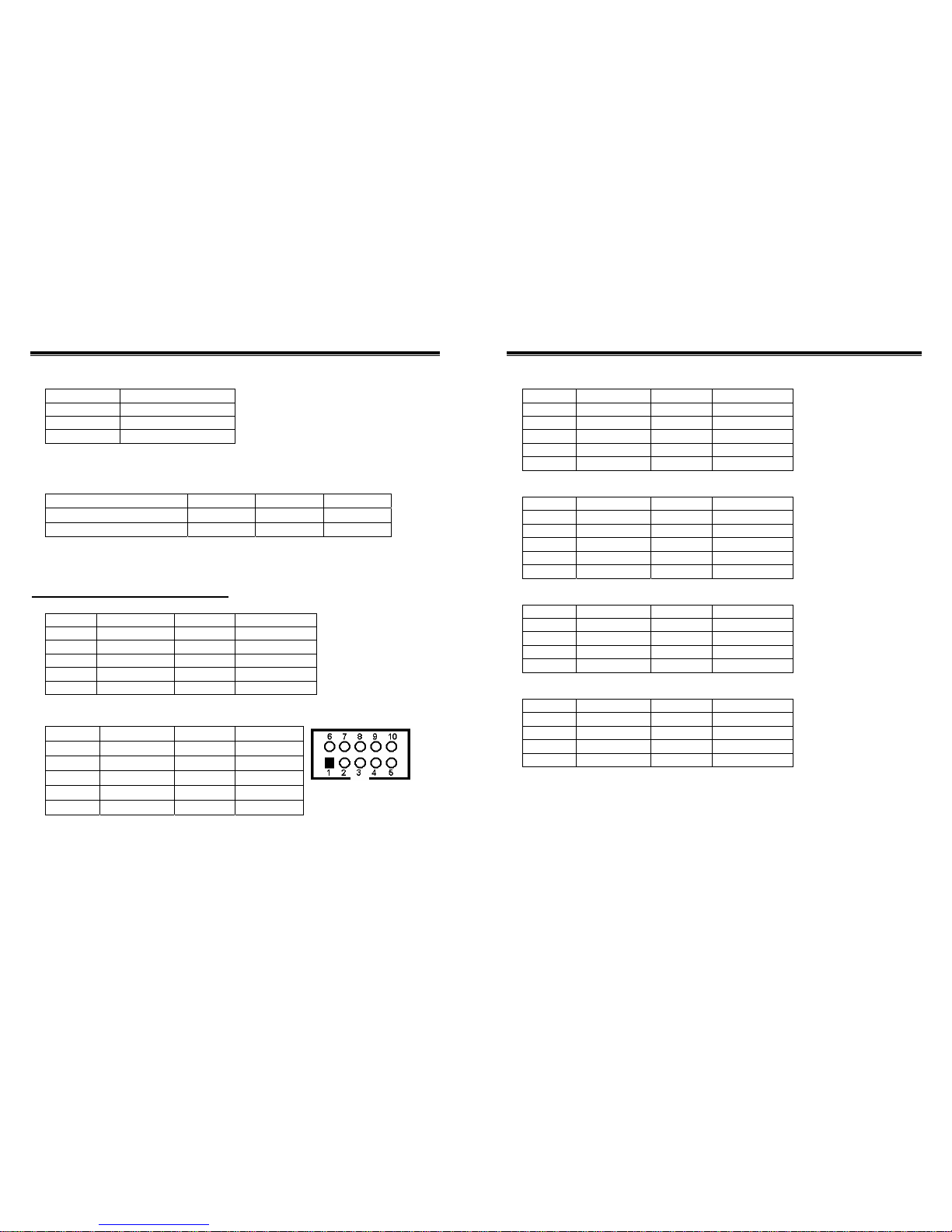
JP2: Power Good Selector (2.0mm)
JP3, JP5: RS232 / 422 / 485 Selector for COM2 (2.0mm)
TYPE JP5 (3x4/2mm) JP3 (2x3/2mm)
RS-232 *
1-2, 4-5, 7-8, 10-11 1-2
RS-422
2-3, 5-6, 8-9, 11-12 3-4
RS-485
2-3, 5-6, 8-9, 11-12 5-6
JP4: COM1, 2 Voltage Selector (2.0mm)
Voltage +12V(DC) R.I. * +5V(DC)
COM1 (JP4) 1-2 3-4 5-6
COM2 (JP4) 7-8 9-10 11-12
Pin 1-2 * External Power Good (Default)
Pin 2-3 Internal Power Good
User’s Manual 7
JP6: Voltage Selector for LCD panel (2.0mm)
LCD power JP6 (2.54mm)
Pin-1, 2 +3.3V
Pin-3, 4 +5V
Pin-5, 6 * +12V
Caution: Improper setting will damage LCD panel.
UC-COM56: Voltage Selector for COM3~COM6 (2.0mm)(Optional Item)
Voltage +12V(DC) R.I. * +5V(DC)
COM4 (JP1), COM6(JP2) 1-2 3-4 5-6
COM3 (JP1), COM5(JP2) 7-8 9-10 11-12
Part 2: Onboard Connectors
J1: PS/2 Keyboard / Mouse Pin Header Connector (2.54mm)
Pin No. Signal (KB) Pin No. Signal (MS)
1 KB Data 2 MS Data
3 KEY 4 KEY
5 GND 6 GND
7 +5V(DC) 8 +5V(DC)
9 KB_CLK 10 MS_CLK
J2: Box Header Type Connector for COM2 port (RS-232)
Pin No. Function Pin No. Function
1
DCD
6
DSR
2
RXD
7
RTS
3
TXD
8
CTS
4
DTR
9
RI
5
GND
10
N.C
8 The ENDAT-4066i System Board
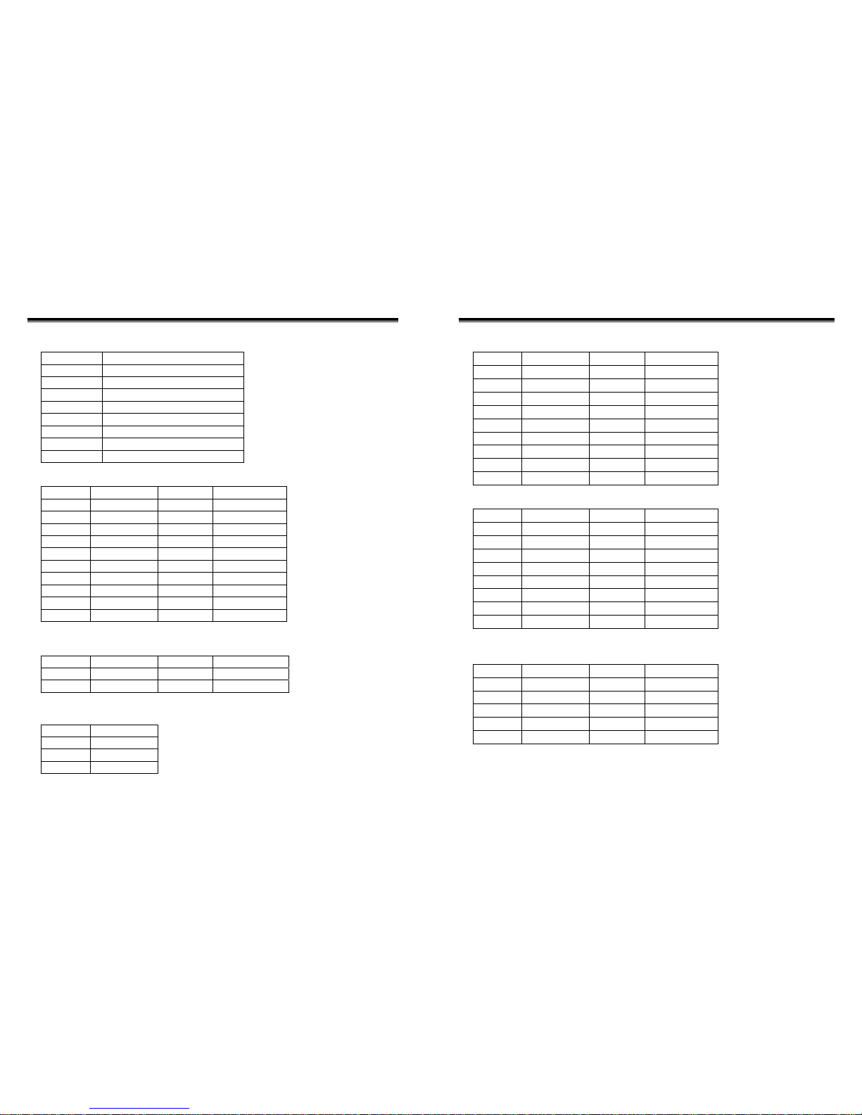
J3, J4: USB port (2.54mm)
Pin No. Function Pin No. Function
1 USB_VCC 2 USB_VCC
3 USBD 2/4- 4 USBD 3/ 5-
5 USBD 2/4+ 6 USBD 3/5+
7 USB_GND 8 USB_GND
9 USB_GND 10 USB_GND
J5: DIGITAL I/O (2.54mm)
Pin No. Function Pin No. Function
1
DIO-O0
2
DIO-I0
3
DIO-O1
4
DIO-I1
5
+12V
6
+12V
7
KEY
8
+3.3V
9
GND
10
GND
J6: CD IN, LINE OUT (2.54mm)
Pin No. Function Pin No. Function
1
LO_J_R
2
CDR
3
GND_AUD
4
CDGND
5
GND_AUD
6
CDGND
7
LO_J_L
8
CDL
J7: Microphone IN & LINE IN (2.54mm)
Pin No. Function Pin No. Function
1
MICIN1
2
LINE_R
3
GND
4
GND
5
GND
6
GND
7
MICIN2
8
LINE_L
User’s Manual 9
J9: Header for Case Panel (2.54mm)
Pin No. Function
1(-), 2(+) IDE active LED
3,6 External Speaker
4,5 Buzzer On/Off
7,8 Hardware Reset Sw itch
9(+), 10(-) Power LED
11,12 ATX Power On/Off
13,14 Close: Enable WDT function
15(+), 16(-) SATA active LED
ATXPWR: Power Supply Connector (3.96mm)
Pin No. Function Pin No. Function
1
+3.3V
2
+3.3V
3
+3.3V
4
-12V
5
GND
6
GND
7
+5V
8
PS-ON
9
GND
10
GND
11
+5V
12
GND
13
GND
14
GND
15
POWER OK
16
-5V
17
5V_SB
18
+5V
19
+12V
20
+5V
CN2: Power Supply Connector (3.96mm)
Pin No. Function Pin No. Function
1
GND
2
+12V
3
GND
4
+12V
FAN1, FAN2: CPU / 2nd Cooling Fan Connector
Pin No. Function
1
Sensor Pin.
2
+12V
3
GND
10 The ENDAT-4066i System Board
CN5: Printer (LPT1) Port
Pin No. Description Pin No. Description
1
STB#
10
ACK#
2
PD0
11
BUSY
3
PD1
12
PE
4
PD2
13
SLCT
5
PD3
14
AFD#
6
PD4
15
ERR#
7
PD5
16
INIT#
8
PD6
17
SLIN#
9 PD7 18-25 GND
CN6: CRT Connector
Pin No. Description Pin No. Description
1
RED
9
N.C / +5V
2
GREEN
10
GND
3
BLUE
11
N.C
4 N.C 12 DDC DAT
5 GND 13 H-Sync
6 GND 14 V-Sync
7
GND
15
DDC CLK
8 GND
D-SUB Type Connector for COM2 port (RS-422Æ 4 Wire)
Pin No. Function Pin No. Function
1 –TXD 6 NA
2
+RXD
7
NA
3
+TXD
8
NA
4
NA
9
–RXD
5
NA
 Loading...