

Endace DAG 4.5G2 Card, DAG 4.5G4 Card, DAG 4.5GF Card User Manual

DAG 4.5G2/G4/GF Card
User Guide
EDM01-18

EDM 01-18 DAG 4.5G2/G4/GF Card User Guide
p
Published by:
Endace Limited
Building 7
Lambie Drive
PO Box 76802
Manukau City 1702
New Zealand
Phone: +64 9 262 7260
Fax: +64 9 262 7261
support@endace.com
www.endace.com
International Locations
New Zealand
Endace Technology® Ltd
Level 9
85 Alexandra Street
PO Box 19246
Hamilton 2001
New Zealand
Phone: +64 7 839 0540
Fax: +64 7 839 0543
Copyright 2005-2006© Endace Limited. All rights reserved. No part of this publication may be reproduced,
stored in a retrieval system, or transmitted, in any form or by any means electronic, mechanical, photocopying,
recording, or otherwise, without the prior written permission of the publisher.
Americas
Endace USA® Ltd
Suite 220
11495 Sunset Hill Road
Reston
Virginia 20190
United States of America
Phone: ++1 703 382 0155
Fax: ++1 703 382 0155
re1
EDM01.06-17
Europe, Middle East & Africa
Endace Europe® Ltd
Sheraton House
Castle Park
Cambridge CB3 0AX
United Kingdom
Phone: ++44 1223 370 176
Fax: ++44 1223 370 040
©2005-2006 Version 4: August 2006

EDM 01-18 DAG 4.5G2/G4/GF Card User Guide
Protection Against Harmful Interference
When present on equipment this manual pertains to, the statement "This device complies with part 15 of the FCC rules"
specifies the equipment has been tested and found to comply with the limits for a Class A digital device, pursuant to Part 15
of the Federal Communications Commission [FCC] Rules.
These limits are designed to provide reasonable protection against harmful interference when the equipment is operated in a
commercial environment.
This equipment generates, uses, and can radiate radio frequency energy and, if not installed and used in accordance with the
instruction manual, may cause harmful interference to radio communications.
Operation of this equipment in a residential area is likely to cause harmful interference in which case the user will be
required to correct the interference at his own expense.
Extra Components and Materials
The product that this manual pertains to may include extra components and materials that are not essential to its basic
operation, but are necessary to ensure compliance to the product standards required by the United States Federal
Communications Commission, and the European EMC Directive. Modification or removal of these components and/or
materials, is liable to cause non compliance to these standards, and in doing so invalidate the user’s right to operate this
equipment in a Class A industrial environment.
Disclaimer
Whilst every effort has been made to ensure accuracy, neither Endace Limited nor any employee of the company, shall be
liable on any ground whatsoever to any party in respect of decisions or actions they may make as a result of using this
information.
Endace Limited has taken great effort to verify the accuracy of this manual, but assumes no responsibility for any technical
inaccuracies or typographical errors.
In accordance with the Endace Limited po licy of continuing development, design and specifications are subject to change
without notice.
©2005-2006 Version 4: August 2006

EDM 01-18 DAG 4.5G2/G4/GF Card User Guide
©2005-2006 Version 4: August 2006

EDM 01-18 DAG 4.5G2/G4/GF Card User Guide
Table of Contents
Chapter 1: Introduction 1
Overview 1
Purpose of this User Guide 1
System Requirements 2
Card Description 3
Card Architecture 4
Extended Functions 6
Chapter 2: Installation 9
Introduction 9
DAG Device Driver 9
Inserting the DAG Card 9
Port Connectors 10
Pluggable Optical Transceivers 10
Pluggable Copper Transceivers 11
Chapter 3: Configuring the Card 13
Introduction 13
Line Types 13
LEDs and Inputs 14
Receiver Port Signal Levels 14
Load the FPGA Image 15
Display Current Configuration 15
Auto-Negotiation 16
Interface Statistics 17
Chapter 4: Capturing Data 19
Starting a Session 19
Setting Captured Packet Size 19
High Load Performance 21
Transmitting 22
Chapter 5: Synchronizing Clock Time 25
Overview 25
DUCK Configuration 25
Common Synchronization 25
Timestamps 26
Configuration Tools 26
Card with Reference 27
Single Card No Reference 29
Two Cards No Reference 29
Connector Pin-outs 31
Chapter 6: Data Formats 33
Overview 33
Generic Header 33
Type-2 Record 34
Type 16 Record 35
Chapter 7 Troubleshooting 37
Reporting Problems 37
Version History 39
©2005-2006 i Version 4: August 2006

EDM 01-17 DAG 4.5G2/G4/GF Card User Guide
©2005-2006 ii Version 4: August 2006

Chapter 1: Introduction
EDM 01-18 DAG 4.5G2/G4/GF Card User Guide
Overview
Purpose of this User Guide
Note: Unless specifically stated otherwise, throughout this User Guide
“DAG 4.5 card” refers to the DAG 4.5G2/G4/and GF cards.
The Endace DAG 4.5 card provides the means to transfer data at the full
speed of the network into the memory of the host PC, with zero packet loss
guaranteed in even worst-case conditions. Further, unlike a NIC, Endace
products actively manage the movement of network data into memory
without consuming any of the host PC's resources. The full attention of the
CPU remains focused on the analysis of incoming data without a constant
stream of interruptions as new packets arrive from the network. For a busy
network link, this feature has a turbo-charging effect similar to that of adding
a second CPU to the system.
The DAG 4.5 card provides independent two or four port Ethernet network
monitoring at Gigabit speeds and supports header only or variable length
capture. It is capable of transmitting and receiving on each channel
simultaneously allowing a single card to operate inline, monitoring and
transmitting in both directions on a full duplex link.
The purpose of this User Guide is to provide you with an understanding of
the DAG card architecture and functionality and to guide you through the
following:
• Installing the card and associated software and firmware,
• Configuring the card for your specific network requirements,
• Running a data capture session,
• Synchronizing clock time,
• Output data formats
You can also find additional information relating to functions and features of
the DAG 4.5 card in the following documents which are available from the
Support section of the Endace website at
• EDM04-08 Configuration and Status API Programming Guide
• EDM04-10 Data Stream Manager API Programming Guide
• EDM04-07 DSM Loader User Manual
This User Guide and the Linux and Windows
PDF format on the installation CD shipped with your DAG 4.5 card.
©2005-2006 1 Version 4: August 2006
www.endace.com:
®
Guides are also available in

EDM 01-17 DAG 4.5G2/G4/GF Card User Guide
System Requirements
General
The minimum system requirements for the DAG 4.5 card are :
• PC, at least Intel Xeon 1.8GHz or faster,
• Minimum of 256 MB RAM,
• At least one free PCI-X slot supporting 66-133 MHz operation,
• Software distribution requires 60MB free space,
Operating System
This User Guide assumes you are installing the DAG card in a PC which
already has an operating system installed.
However for convenience, a copy of Debian Linux 3.1 (Sarge) is provided as
a bootable ISO image on the CD that is shipped with the DAG card.
To install either the Linux/FreeBSD or Windows® operating system please
refer to the following documents which are also included on the CD that is
shipped with the DAG card.
• EDM04-01 Linux FreeBSD Software Installation Guide
®
• EDM04-02 Windows
Software Installation Guide
Other Systems
For advice on using an operating system that is substantially different from
either of those specified above, please contact Endace Customer Support at
support@endace.com
©2005-2006 2 Version 4: August 2006
EDM 01-18 DAG 4.5G2/G4/GF Card User Guide
Card Description
The DAG 4.5 card provides two or four optical or copper Gigabit Ethernet
interfaces. It is capable of full line rate (1,000Mbps) capture and transmission
of Ethernet traffic and is protocol independent. Full packet capture at line
rate allows recording of all header information and/or payload with a high
precision timestamp.
Note: The DAG 4.5G2/GF has two ports, the DAG 4.5G4 has four
ports.
The key features of the card are:
• Two or four SFP ports for 1000Base-SX or 1000Base-LX optical
Ethernet or 1000Base-T copper Ethernet,
• Header only or variable length capture,
• Full line rate transmit,
• 100% capture into host memory at full line rate for IP packets from 48 to
9600 bytes
• Conditioned clock with PPS input and local synchronization capability.
• PCI-X 64-bit 66/100/133 MHz bus interface with 3V signaling.
• Failsafe optical relays to connect the two ports on the card in event of a
power failure (DAG 4.5GF only).
Pluggable Optical
Connectors x 4.
Note: Pluggable
copper connectors
are also supported.
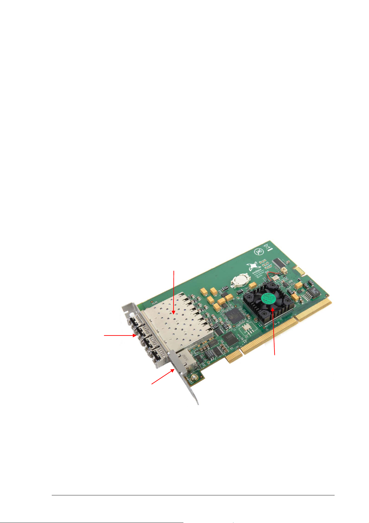
The DAG 4.5G4 card is shown below:
SFP Cages
FPGA with
fan fitted
RJ-45 socket for
time synchronization
Note: Although the DAG 4.5G4 supports full line rate capture or
transmit across all four ports, maximum combined throughput (i.e.
simultaneous capture and transmission) is limited by the bandwidth of
the PCI-X.
©2005-2006 3 Version 4: August 2006

EDM 01-17 DAG 4.5G2/G4/GF Card User Guide
The DAG 4.5G2 card is shown below:
SFP Cages
Pluggable Optical
Connectors x 2.
Note: Pluggable
copper connectors
are also supported.
9-pin socket for time
synchronization
FPGA with
Heatsink fitted
Note: The DAG 4.5G2/GF card is capable of simultaneous capture and
transmission at full line rate across both ports.
Card Architecture
Serial Ethernet network data received by two 1000Base interfaces flows
directly into the Field Programmable Gate Array (FPGA).
The FPGA contains the packet processor, PCI-X interface logic and the
DAG Universal Clock Kit (DUCK) timestamp engine. The DUCK
provides high resolution per-packet timestamps which can be accurately
synchronized.
Note: For further information on the DUCK and time synchronizing
please refer to
Chapter 5: Synchronizing Clock Time later in this
User Guide.
Because of component close association, packets are time-stamped
accurately. Time stamped packet records are stored in an external FIFO
memory before transmission to the host.
©2005-2006 4 Version 4: August 2006
EDM 01-18 DAG 4.5G2/G4/GF Card User Guide
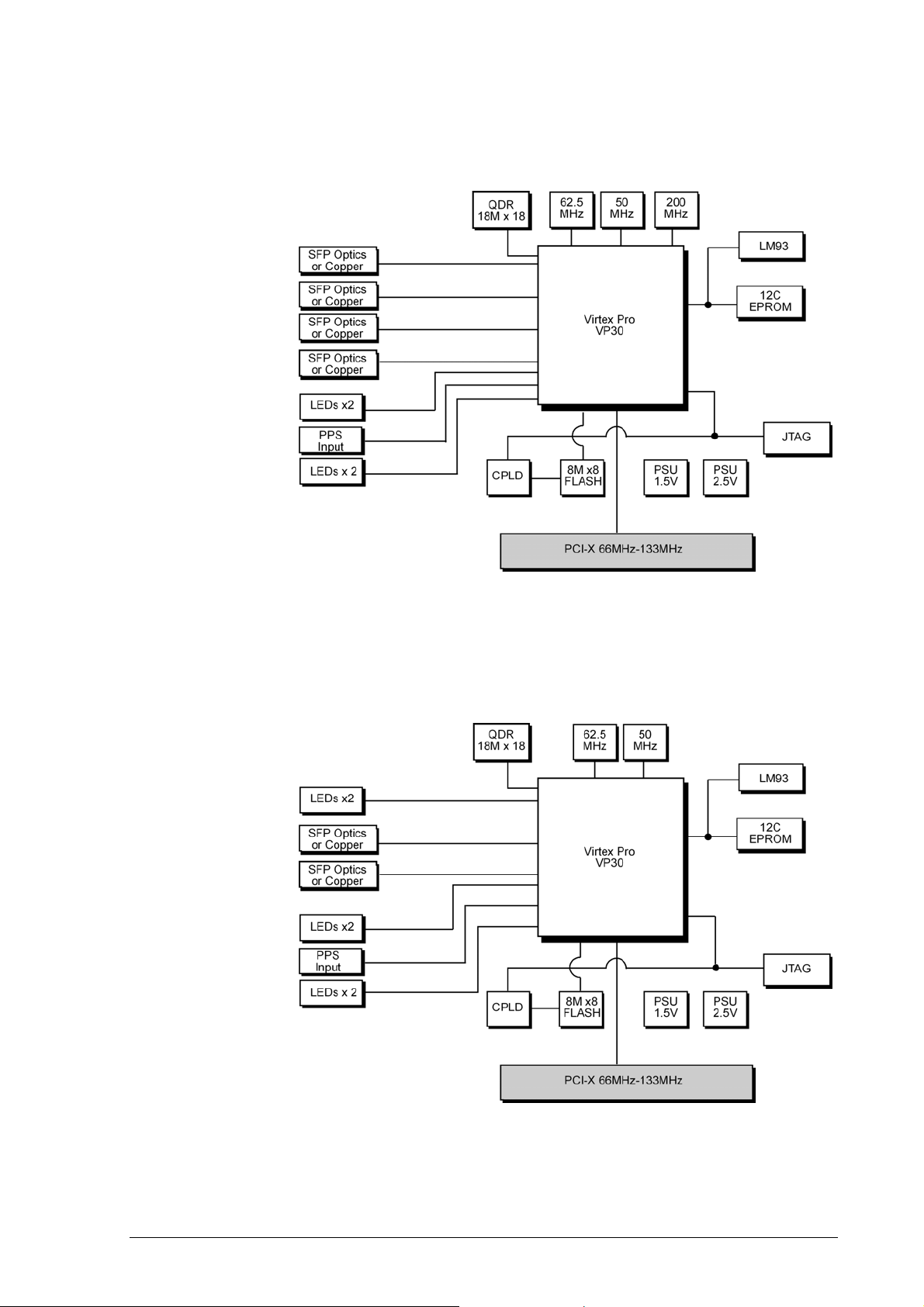
DAG 4.5G4
The diagram below shows the DAG 4.5G4 card’s major components and
flow of data.
DAG 4.5G2
The diagram below shows the DAG 4.5G2 card’s major components and
flow of data.
©2005-2006 5 Version 4: August 2006
EDM 01-17 DAG 4.5G2/G4/GF Card User Guide
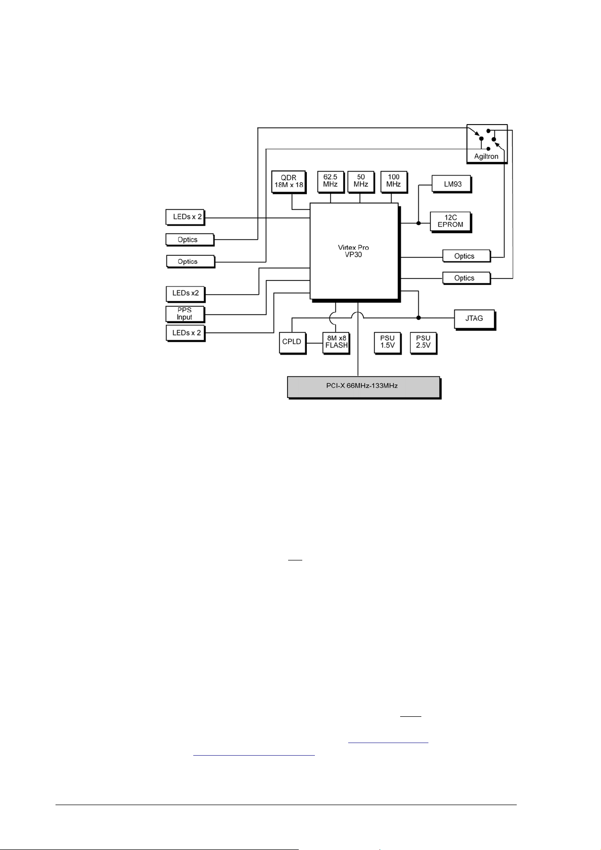
DAG 4.5GF
The diagram below shows the DAG 4.5GF card’s major components and
flow of data:
Extended Functions
Failsafe Relays
The DAG 4.5GF has failsafe optical relays which allow you to connect the
two ports in the event of a power interruption or software or hardware failure
on the host. This means that in such an event the traffic can be switched to
bypass the DAG card while still maintaining network connectivity.
The failsafe relays are controlled via an optical switch on the DAG card and
can be configured to either fail-open or fail-closed.
Note: This feature is
Fail-Open
Fail-open is the default configuration and is for use in situations where the
nature of the event means that traffic must be stopped. In fail-open mode the
network connection will switch to open circuit in the event of a failure which
is effectively the same as disconnecting the DAG card from the network.
Fail-Closed
Fail-closed mode is for use in situations when the nature of the event means
that traffic must still flow. In this mode the two ports are connected together
so that all traffic received on Port A is transmitted on Port B and all traffic
received on Port B is transmitted on Port A.
not available on the DAG 4.5G2/G4 cards.
Note: To implement the fail-closed mode you
relays using the
using
dagwatchdog please refer to Starting a Session in
Chapter 4: Capturing Data later in this User Guide.
©2005-2006 6 Version 4: August 2006
dagwatchdog command. For further information on
must engage the failsafe

EDM 01-18 DAG 4.5G2/G4/GF Card User Guide
Extended
Functions
(cont.)
Data Stream Manager
The DAG 4.5 card supports the Data Stream Manager (DSM) feature. DSM
allows you to drop or route packets to a particular receive stream based on the
packet contents, physical port and the output of two load balancing
algorithms.
The DSM logic is implemented in firmware on the DAG card, it does not
require intervention from the host CPU once it is configured.
Filter / Load Balancing Block
Packets are received from the line and stamped with an ERF header, then
passed to the filter and load balancing block. The filter block applies eight
bit-mask filters simultaneously to the start of the packet, producing a single
true/false value for each filter.
The load balancing block applies two algorithms to the packet data, also
producing one true/false Boolean output per algorithm.
Lookup Table Block
The lookup table accepts the filter and load balancing outputs. It also receives
the physical port the packet arrived on and calculates a classification (also
known as color) for the packet.
Coloriser and Drop Block
The color is then passed to the Coloriser And Drop (CAD) block to check if
the packet should be dropped. If not the color is inserted into the packet ERF
record header and the packet record is passed to the packet record
multiplexer.
Packet Record Multiplexer (ERF MUX)
The ERF MUX looks at the color information contained in the packet record
and determines which receive stream the packet record should be routed to.
Note: For detailed information on using the Data Stream Manager
please refer to EDM04-10 Data Stream Management API
Programming Guide and EDM04-07 dsm-loader User Guide available
from the Support section of the Endace website at
www.endace.com.
Inline Forwarding
The DAG 4.5 card supports inline forwarding which enables the card to
receive and transmit packets directly from a single memory. This allows you
to forward packets from one interface to the other without the requirement to
copy them. Using inline forwarding you can receive, inspect, filter and
forward packets between two ports.
The DAG 4.5 can perform inline forwarding at 100% of line rate in both
directions. However when using all four ports on the DAG 4.5G4 the
maximum throughput may be limited by the bandwidth of the PCI-X.
dagfwddemo which is a tool supplied with your DAG card demonstrates how
you can apply a user-defined BSD Packet Filter (BPF) to the traffic
forwarded by the DAG card. Packets which match the filter are forwarded,
while packets that do not match are dropped.
For more detailed information on inline forwarding and using
dagfwddemo
please refer to the EDM 04-04: dagfwddemo User Guide available from the
support section of the Endace website at
www.endace.com.
©2005-2006 7 Version 4: August 2006

EDM 01-17 DAG 4.5G2/G4/GF Card User Guide
©2005-2006 8 Version 4: August 2006
 Loading...