

Endace DAG 3.7GF, DAG 3.7G Series, DAG 3.7GP User Manual

EDM01-07: DAG 3.7G Card User Guide
Published by:
Endace Measurement Systems® Ltd
Building 7
17 Lambie Drive
PO Box 76802
Manukau City 1702
New Zealand
Phone: +64 9 262 7260
Fax: +64 9 262 7261
support@endace.com
www.endace.com
International Locations
New Zealand
Endace Technology® Ltd
Level 9
85 Alexandra Street
PO Box 19246
Hamilton 2001
New Zealand
Phone: +64 7 839 0540
Fax: +64 7 839 0543
Copyright 2005 ©All rights reserved. No part of this publication may be reproduced, stored in a retrieval system,
or transmitted, in any form or by any means electronic, mechanical, photocopying, recording, or otherwise, without
the prior written permission of the publisher.
Americas
Endace USA® Ltd
Suite 220
11495 Sunset Hill Road
Reston
Virginia 20190
United States of America
Phone: ++1 703 382 0155
Fax: ++1 703 382 0155
Europe, Middle East & Africa
Endace Europe® Ltd
Sheraton House
Castle Park
Cambridge CB3 0AX
United Kingdom
Phone: ++44 1223 370 176
Fax: ++44 1223 370 040
Version 7: May 2006 ©2005

EDM01-07: DAG 3.7G Card User Guide
Protection Against Harmful Interference
When present on equipment this manual pertains to, the statement "This device complies with part 15 of the FCC rules"
specifies the equipment has been tested and found to comply with the limits for a Class A digital device, pursuant to Part 15
of the Federal Communications Commission [FCC] Rules.
These limits are designed to provide reasonable protection against harmful interference when the equipment is operated in a
commercial environment.
This equipment generates, uses, and can radiate radio frequency energy and, if not installed and used in accordance with the
instruction manual, may cause harmful interference to radio communications.
Operation of this equipment in a residential area is likely to cause harmful interference in which case the user will be
required to correct the interference at his own expense.
Extra Components and Materials
The product that this manual pertains to may include extra components and materials that are not essential to its basic
operation, but are necessary to ensure compliance to the product standards required by the United States Federal
Communications Commission, and the European EMC Directive. Modification or removal of these components and/or
materials, is liable to cause non compliance to these standards, and in doing so invalidate the user’s right to operate this
equipment in a Class A industrial environment.
Disclaimer
Whilst every effort has been made to ensure accuracy, neither Endace Measurement Systems Limited nor any employee of
the company, shall be liable on any ground whatsoever to any party in respect of decisions or actions they may make as a
result of using this information.
Endace Measurement Systems Limited has taken great effort to verify the accuracy of this manual, but assumes no
responsibility for any technical inaccuracies or typographical errors.
In accordance with the Endace Measurement Systems policy of continuing development, design and specifications are
subject to change without notice.
©2005 Version 7: May 2006

EDM01-07: DAG 3.7G Card User Guide
Version 7: May 2006 ©2005

Table of Contents
EDM01-07: DAG 3.7G Card User Guide
Chapter 1: Introduction 1
Overview 1
Purpose of this User Guide 1
System Requirements 1
Card Description 2
Card Architecture 3
Overview 3
NIC Functionality 4
Memory Holes 4
Failsafe Relays 4
Chapter 2: Installation 5
Introduction 5
DAG Device Driver 5
Inserting the DAG Card 5
Connecting the Interfaces 5
Card Sensitivity 6
Chapter 3: Configuring the Card 7
Introduction 7
Engaging Failsafe Relays 7
LEDs and Inputs 7
Configuration Utility 8
Default Configuration 8
Interface Statistics 10
Chapter 4: Capturing Data 13
Starting a Session 13
High Load Performance 13
Overview 13
Avoiding Packet Loss 13
Detecting Packet Losses 14
Increasing Buffer Size 14
Packet Transmission 14
In-Line Forwarding 16
Chapter 5: Synchronising Clock Time 17
Overview 17
DUCK Configuration 17
Common Synchronization 17
Timestamps 18
Configuration Tools 19
Card with Reference 20
Single Card No Reference 21
Two Cards No Reference 21
Connector Pin-outs 23
©2005 i Version 7: May 2006

EDM01-07: DAG 3.7G Card User Guide
Table of Contents
Chapter 6: Data Formats 25
Overview 25
Generic Header 25
Type 2 Record 26
Chapter 7: Troubleshooting 27
Reporting Problems 27
(cont.
)
Version 7: May 2006 ii ©2005

Chapter 1:
Introduction
EDM01-07: DAG 3.7G Card User Guide
Overview
Purpose of
this User
Guide
The Endace DAG 3.7G series consist of two PCI-bus card types, DAG 3.7GF
and the DAG 3.7GP.
The installation of an Endace DAG 3.7G series card on a PC begins with
installing the operating system and the Endace software. This is followed by
fitting the card and connecting the ports.
The purpose of this User Guide is to provide you with an understanding of
the DAG card architecture and functionality and to guide you through the
following:
• Installing the Card and associated software and firmware
• Configuring the card for your specific network requirements
• Running a data capture session
• Synchronising clock time
• Data formats
You can also find additional information relating to functions and features of
the DAG 3.7G card in the following documents which are available from the
Support section of the Endace website at www.endace.com:
• EDM04-08 Configuration and Status API Programming Guide,
This User Guide and the Linux and Window Guides are also available in PDF
format on the Installation CD shipped with your DAG 3.7G card.
System
Requirements
General
The minimum system requirements for the DAG 3.7G card are :
• PC, at least Pentium II 400 MHz, Intel 440BX, GX or newer chip set
• 256 MB RAM
• At least one free 3.3V 32 or 64 bit PCI slot
• 30MB free disk space for software distribution
Note: A 64-bit PCI slot is recommended in order to maximize
performance.
©2005 1 Version 7: May 2006
EDM01-07: DAG 3.7G Card User Guide
Card
Description
Operating System
This User Guide assumes you are installing the DAG card in a PC which
already has an operating system installed.
However for convenience, a copy of Debian Linux 3.1 (Sarge) is provided as
a bootable ISO image on the CDs that is shipped with the DAG card.
To install either the Linux/FreeBSD or Windows operating system please
refer to the following documents which are also included on the CD that is
shipped with the DAG card.
• EDM04-01 Linux FreeBSD Software Installation Guide
• EDM 04-02 Windows Software Installation Guide
Other Systems
For advice on using an operating system that is substantially different from
either of those specified above, please contact Endace Customer Support at
support@endace.com
The DAG 3.7GF has failsafe relays to connect the two ports on the card in
event of a power failure. This failsafe feature is intended for use in inline
forwarding applications. The DAG 3.7GP does not have the failsafe feature.
The DAG Ethernet ports will operate in half duplex or full duplex modes.
The DAG 3.7G series card by default finds the fastest link configuration
possible with the peer device using Ethernet Autonegotiation.
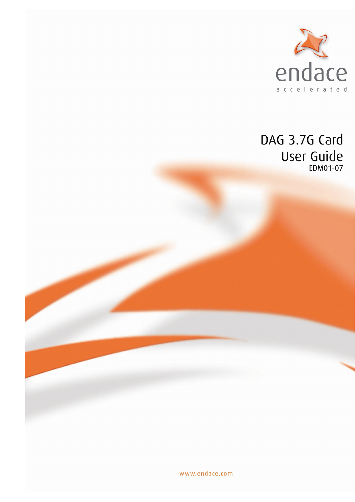
The DAG 3.7GP card is shown below:
Version 7: May 2006 2 ©2005
EDM01-07: DAG 3.7G Card User Guide
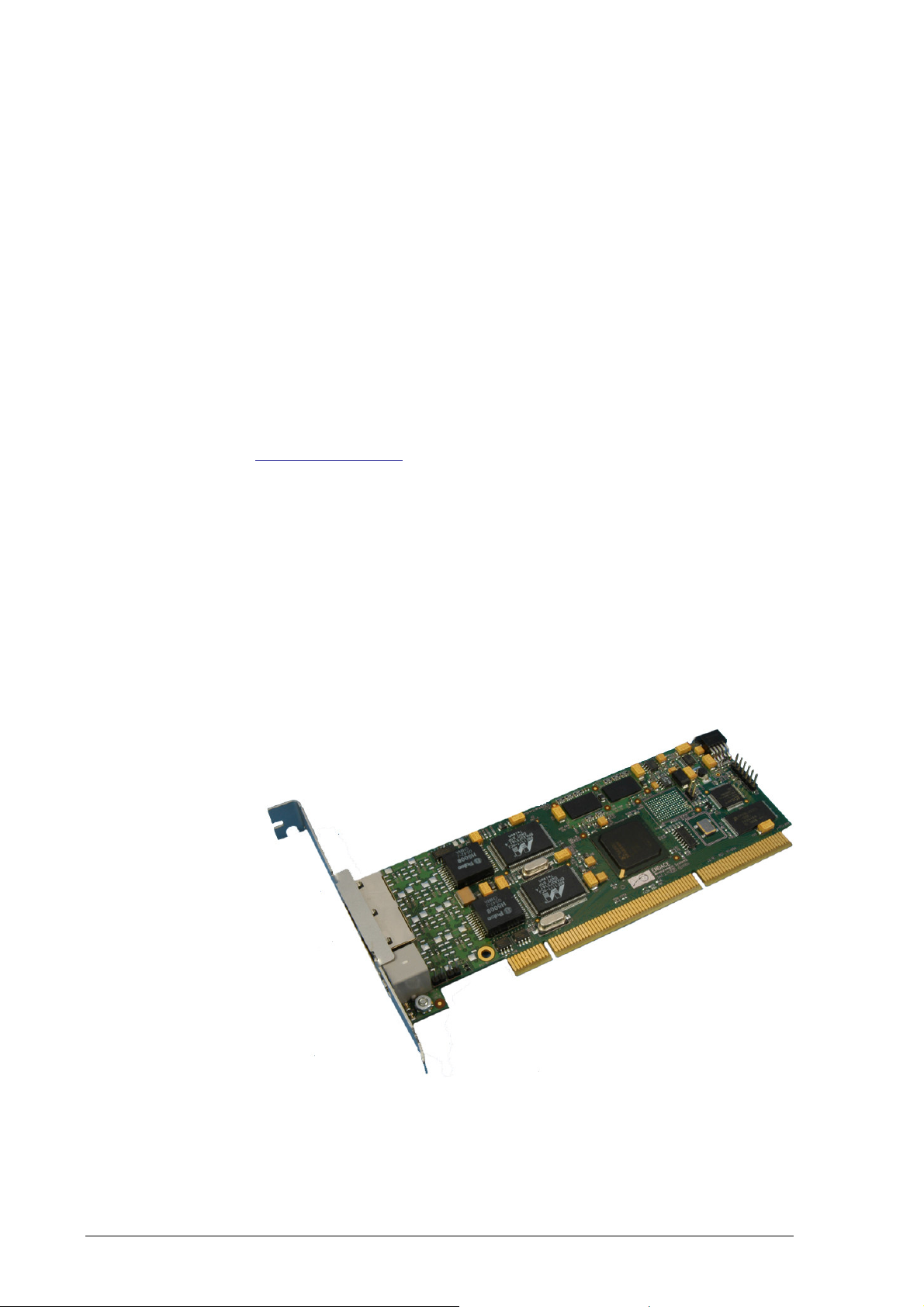
Card
Architecture
The DAG 3.7GF card is shown below:
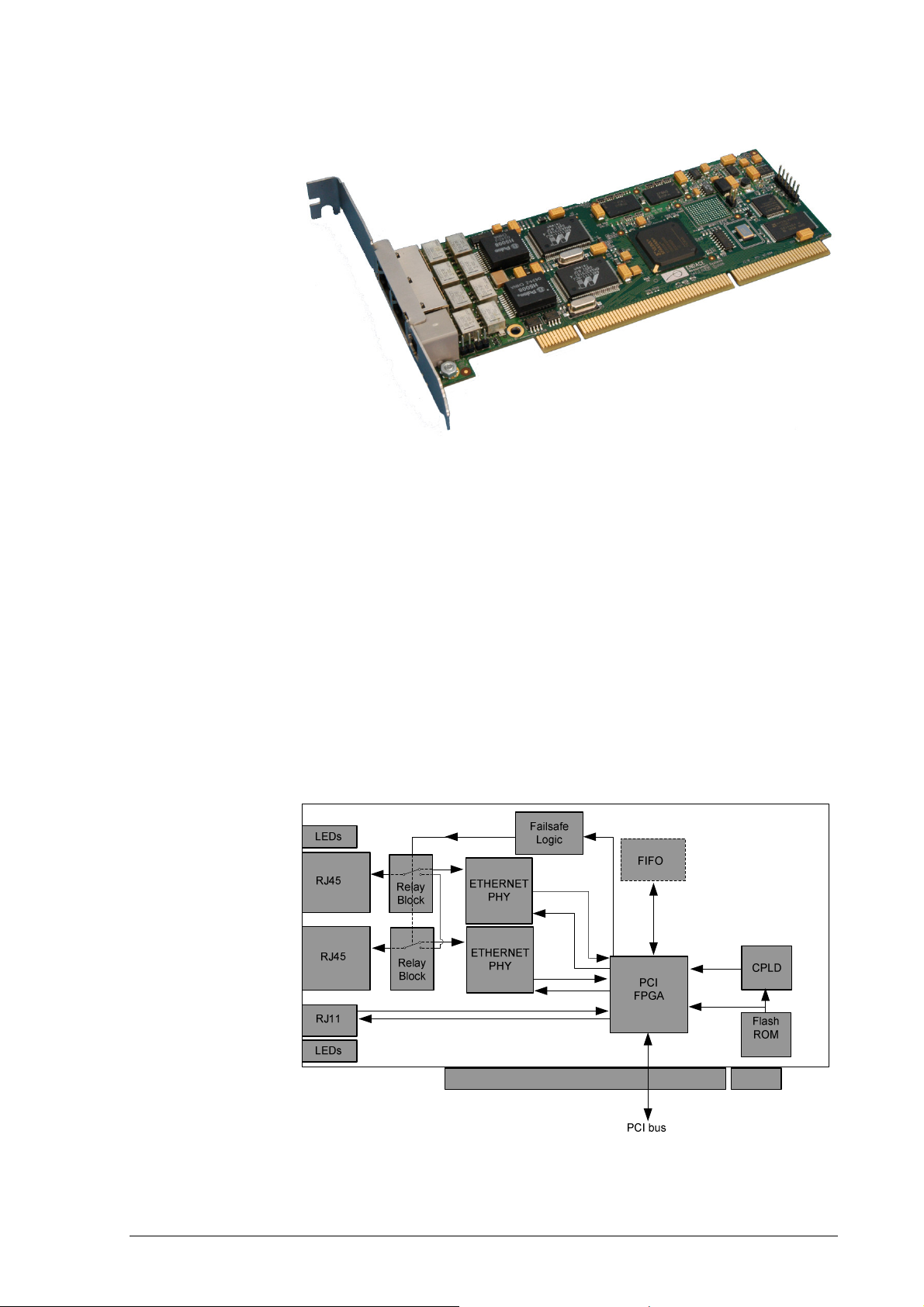
Overview
The DAG 3.7G series card is designed for packet capture and generation on
Ethernet networks.
Ethernet data is received by a DAG 3.7G series card interfaces, and fed
through framers into the Xilinx FPGA.
This FPGA contains an Ethernet processor and the DUCK timestamp engine.
Because of close association of the components, packets are time-stamped
accurately. Time stamped packet records are stored by the FPGA, which
interfaces to the PCI bus. All packet records are written to host PC memory
during capture operations.
The following diagram shows the card’s major components and the flow data:
©2005 3 Version 7: May 2006

EDM01-07: DAG 3.7G Card User Guide
NIC Functionality
The DAG 3.7G series card have two 10/100/1000 Mbps Copper Ethernet
There default configuration is as if the DAG card was a NIC, and can be
connected to a hub, switch or router port directly.
Each DAG 3.7G port can also be connected to a NIC card. The DAG 3.7G
cards support automatic MDI/MDI-X switching, so can be connected to a
NIC using either an Ethernet straight-through or cross-over cable. When
using the failsafe feature of the DAG 3.7GF, there are some advantages to
using a straight through cable rather than a cross-over one. The DAG card
captures all packets received on each port, similar to a NIC in promiscuous
mode.
Memory Holes
Memory hole configuration is dependant on the application requirements. For
a receive-only configuration, two memory holes are available, on each port.
For packet forwarding applications, only one memory hole can be utilised.
Failsafe Relays
The DAG 3.7GF card failsafe relays are capable of either:
• Connecting the two ports together as a pass-through link
• Connecting both ports to the FPGA to enable data capture. This feature
is not available on 3.7GP cards.
Version 7: May 2006 4 ©2005

Chapter 2:
If you have not already completed this please follow the instructions in
Installation
EDM01-07: DAG 3.7G Card User Guide
Introduction
DAG Device
Driver
Note: Throughout this document the “DAG 3.7G” refers to both the
DAG 3.7GF card and the DAG 3.7GP card.
The DAG 3.7G card can be installed in any free 32-bit or 64-bit Bus
Mastering PCI slot.
Although the driver supports up to four DAG cards by default in one system,
due to bandwidth limitations there should not be more than one card on a
single PCI-bus.
The cards make very heavy use of PCI-bus data transfer resources. This is
not usually a limitation as for most applications a maximum of two cards only
can be used with reasonable application performance.
The DAG device driver must be installed before you install the DAG card
itself.
EDM04-01 Linux FreeBSD Software Installation Guide or EDM 04-02
Windows Software Installation Guide as appropriate, which are
included on the CD shipped with the DAG card.
Inserting the
DAG Card
Connecting
the Interfaces
To insert the DAG card in the PC follow the steps described below:
• Turn power to the computer OFF,
• Remove the PCI bus slot screw and cover,
• Insert DAG card into PCI bus slot ensuring that it is firmly seated in the
slot,
• Check the free end of the card fits securely into the card-end bracket
that supports the weight of the card,
• Secure the card with the bus slot screw,
• Turn power to the computer ON.
There are two RJ45 connectors on the DAG 3.7G card, and a RJ11 connector.
The RJ45 connectors, furthest from PCI connector, are the network
monitoring ports. These can be connected directly to Ethernet Hubs, Switches
or Router ports with a standard Ethernet cable. The monitoring ports can also
be connected directly to NIC cards using either ethernet cross-over or
straight-through cables.
The RJ11 socket, near the PCI connector, is for the time synchronization
input. This socket should never be connected to a telephone line.
©2005 5 Version 7: May 2006
 Loading...