

ENDA EI141, : EI141-230VAC, EI141-24VAC, EI141-12VAC, EI141-SM Series Manual
ENDA EI141 PROGRAMMABLE INDICATOR
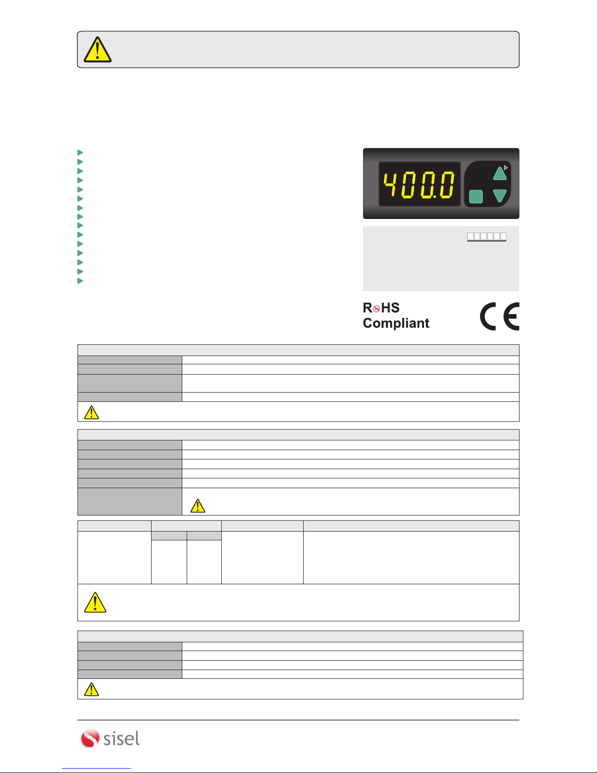
Thank you for choosing ENDA EI141 Programmable Indicator.
SET
EI141
ENDA
PROGRAMMABLE INDICATOR
EI141-E-09-160217
Order Code : EI141 -
1 - Supply Voltage
230VAC...230V AC
24VAC.....24V AC
12VAC.....12V AC
SM...........9-30V DC /7-24V AC
1/3
SİSEL MÜHENDİSLİK ELEKTRONİK SAN. VE TİC. A.Ş.
Şerifali Mah. Y.Dudullu 34775
ÜMRANİYE/İSTANBUL-TURKEY
Tel : +90 216 499 46 64 Pbx. Fax : +90 216 365 74 01
url : www.enda.com.tr
Barbaros Cad. No:18
ENDA
TM
P
l
e
ase rea
d
th
i
s
docu
ment
car
ef
ul
l
y b
e
fo
re
using t
hi
s p
r
od
uc
t
.
T
he gua
ra
ntee
wi
ll
be i
n
v
al
i
dat
ed
if the
devi
c
e
is
damaged b
y
not
f
o
l
l
ow
in
g in
s
tru
c
t
io
ns
deta
i
le
d i
n the
m
a
nual
. The
c
ompa
ny
s
h
al
l no
t b
e
r
es
po
n
si
bl
e f
or any d
a
mage
or l
o
s
s
es h
o
wev
e
r c
a
us
ed,
whi
c
h m
a
y
be
e
xp
erie
nc
ed as
a r
e
s
ul
t of
t
he
i
ns
ta
ll
a
ti
on
or u
s
e
of
thi
s
pr
od
uct
.
- 35x77mm sized.
- 4 digits display.
- Easy to use by front panel keypad.
- Display scale can be adjusted between -1999 and 4000.
- Decimal point can be adjusted between 1. and 3. digits.
- Measurement unit can be displayed.
- Selectable four different standard input types (0-20mA, 4-20mA, 0-1V, 0-10V)
- User can calibrate the device according to specified input type.
- Sampling time can be adjusted in four steps.
- Stores maximum and minimum measurement values.
- The maximum or the minimum values can be hold on the display.
- Current and voltage calibration can be performed.
- Parameter access protection on 3 levels.
- Easy connection by removable screw terminal.
- CE marked according to European Norms.
TECHNICAL SPECIFICATIONS
ENVIRONMENTAL CONDITIONS
Height
Max. 2000m
Ambient / Storage Temperature
Max. Relative Humidity
0 ... +50 °C/-25 ... +70°C (With no icing)
Rated Pollution Degree
80% Relative humidity for temperatures up to 31°C, decreasing linearly to 50% at 40°C.
According to EN 60529 Front panel : IP65
Rear panel : IP20
Do not use the device in locations subject to corrosive and flammable gases.
1
Supply
Power Consumption
Max. 7VA
2.5mm² screw-terminal connections
Wiring
Date Retention
EMC
Safety Requirements
EN 61326-1: 2013
EEPROM (Min. 10 years)
EN 61010-1: 2010 P ( ollution degree 2, overvoltage category II, measurement category I)
ELECTRICAL CHARACTERISTICS
230V AC +10 -20 or 12/24V AC ±10 , 50/60Hz or optional .% % % 9-30V DC / 7-24V AC ±10% SMPS
EI141 Can not be used if measurement category II, III or IV is required.
While the current measuring mode, input impedance becomes 5Ω . Therefore, in current mode, the device must not be connected any
voltage input. Otherwise, the device is broken. While the device is running in the voltage measurement mode and if required to change
to current measurement mode, then firstly the voltage inputs must be removed and after that, input type must be changed to one of the
current measurement modes.
Input Type
0-1V DC voltage
0-10V DC voltage
0-20mA DC current
4-20mA DC current
Input Empedance
Approx. 11kΩ (terminal voltage limits: min. = -2V, max. = 30V)
Approx. Ω (terminal voltage limits: min. = -2V, max. = 30V) 11k
Approx. Ω 5 (applicable terminal voltage is max. 50mA.)
Approx. Ω (applicable terminal voltage is max. 50mA.) 5
0V
±0,5% (of full scale)
0V
±0,5% (of full scale)
0mA
±0,5% (of full scale)
0mA
±0,5% (of full scale)
1.1V
14V
25mA
25mA
Min.
Max.
Measurement Range
Measurement Accuracy
HOUSING
Housing Type
Suitable for flush-panel mounting according to DIN 43 700.
Dimensions
W77xH35xD71mm
Weight
Approx. 250g (after packing)
Enclosure Material
Self extinguishing plastics
While cleaning the device, solvents (thinner, benzine, acid etc.) or corrosive materials must not be used.

SET
EI141
ENDA
PROGRAMMABLE INDICATOR
INPUT
+
GND
1 2 3 4 5 6
7 8 9
10
11 12
EI141-230VAC
PROGRAMMABLE INDICATOR
ENDA INDUSTRIAL ELECTRONICS
230V AC +10% - 20%
50/60Hz 7VA
SN: XXXXXXXXX
8 6 80 4 07 70 3 34 0
Made In Turkey
INPUT
+
GND
1 2 3 4 5 6
7 8 9
10
11 12
EI141-24VAC
PROGRAMMABLE INDICATOR
ENDA INDUSTRIAL ELECTRONICS
24V AC ±10%
50/60Hz 7VA
SN: XXXXXXXXX
8 6 80 4 07 70 3 36 4
Made In Turkey
INPUT
+
GND
1 2 3 4 5 6
7 8 9
10
11 12
EI141-SM
PROGRAMMABLE INDICATOR
ENDA INDUSTRIAL ELECTRONICS
SN: XXXXXXXXX
8 6 80 4 07 70 3 38 8
Made In Turkey
9-30V DC / 7-24V AC
±10% 7VA
EI141-E-09-160217
2/3
SİSEL MÜHENDİSLİK ELEKTRONİK SAN. VE TİC. A.Ş.
Şerifali Mah. Y.Dudullu 34775
ÜMRANİYE/İSTANBUL-TURKEY
Tel : +90 216 499 46 64 Pbx. Fax : +90 216 365 74 01
url : www.enda.com.tr
Barbaros Cad. No:18
ENDA
TM
TERMS
1) Measurement value, measurement unit, the minimum or the maximum measured values are
displayed in the run mode.
Parameter name, parameter value or a user defined unit is displayed in the programming mode.
3) De
Used for making the minimum and the maximum measured values equal in the run mode.
crement or parameter selection key in the programming mode.
2) Increment or parameter selection key in the programming mode.
Used for displaying measurement unit or the max. measured value in the run mode.
4) Used for selecting run and programming modes, displaying
measurement unit or making the minimum and the maximum measured values equal.
adjusting parameters,
4 digits 7 segment yellow LED display
( 2 ),( 3 ),( 4 ),( 5 ) Keypad
( 1 ) Digital display
12.5mm
Micro switch
Character height
Panel cut-out
71,5mm
29,5mm
Note :
1) Panel thickness should be maximum 7 mm.
2) There must be at least 60mm free space
behind the device, otherwise it would be difficult to
remove it from the panel.
DIMENSIONS
Flush mounting
clamp
Panel
Depth
2
71mm
5mm
Flush mounting
clamp
1
Rubber
packing
SETSET
EI141
ENDA
PROGRAMMABLE INDICATOR
35mm
77mm
For removing mounting clamps ;
- Push flush mounting clamps in
direction 1 as shown in the figure below.
Then pull out the clamps in direction 2 .
INPUT
+
GND
1 2 3 4 5 6
7 8 9
10
11 12
EI141-230VAC
PROGRAMMABLE INDICATOR
ENDA INDUSTRIAL ELECTRONICS
230V AC +10% - 20%
50/60Hz 7VA
SN: XXXXXXXXX
8 68 040 7 70 33 40
Made In Turkey
Flush mounting
clamp
1
22
CONNECTION DIAGRAM
ENDA EI141 is intended for installation in control panels. Make sure that the device is used only for intended purpose.
grounded on the instrument side. During an installation, all of the cables that are connected to the device must be free of electrical power. The
device must be protected against inadmissible humidity, vibrations, severe soiling. Make sure that the operation temperature is not exceeded.
All input and output lines that are not connected to the supply network must be laid out as shielded and twisted cables. These cables should not
be close to the power cables or components. The installation and electrical connections must be carried out by a qualified staff and must be
according to the relevant locally applicable regulations.
The shielding must be
2
1
184-253V AC
50/60Hz 7VA
230V AC
Supply
Switch
Cable size: 1,5mm²
Fuse
F 100 mA
250V AC
Neutral
Line
SUPPLY :
NOTE :
Fuse should
be connected
1) Mains supply cords shall meet the requirements of IEC 60227 or IEC 60245.
2) In accordance with the safety regulations, the power supply switch shall bring the identification of the relevant instrument and it should
be easily accessible by the operator.
Note :
Holding screw
0.4-0.5Nm
Equipment is protected throughout
by DOUBLE INSULATION.
 Loading...