

Page 1
Technical Specifications
Supply voltage
230V AC +10% -20% or 12/24V AC/DC ±10%, 50/60Hz or 9-30V DC / 7-24V AC ±10%.
Power consumption
Max. 4VA
2.5mm² screw-terminal connections.
(±1%-15sec) for hour unit, (±1%-1sec) for minute unit
4 digits, 12.5mm, 7 segment yellow LED
Wiring
Scale
Sensitivity/Accuracy
Time Accuracy
Indicator
EMC
Safety requirements
The device is designed to operate in controlled electromagnetic environment)
EN 61326-1: 1997, A1: 1998, A2: 2001 (Performance criterion B is satisfied for EMC tests.
EN 61010-1: 2001 (Pollution degree 2, overvoltage category II)
CONTROL
Control type
Single-setpoint control
On-Off control
Control algorithm
Hysteresis
Adjustable between 0.1 ... 20.0°C.
ELECTRICAL CHARACTERISTICS
ENVIRONMENTAL CONDITIONS
Height
Max. 2000m
80 , up to 40% 31°C decreasing linearly 50% at °C
Ambient/storage temperature
Max. relative humidity
0 ... +50°C/-25 ... 70°C (with no icing)
-50.0 ... +110.0°C (-58.0 ... +230.0°F)
0.1°C / ±1°C
Rated pollution degree
According to EN 60529 Front panel : IP65
Rear panel : IP20
Do not use the device in locations subject to corrosive and flammable gasses.
HOUSING
Housing type
Suitable for flush-panel mounting.
Dimensions
W77xH35xD71mm
Weight
Approx. 250g (Equipment and prob a ) fter packing
Enclosure material
Self extinguishing plastics
ENDA EDT1411P TEMPERATURE CONTROLLER
Thank you for choosing ENDA EDT1411 temperature controller.
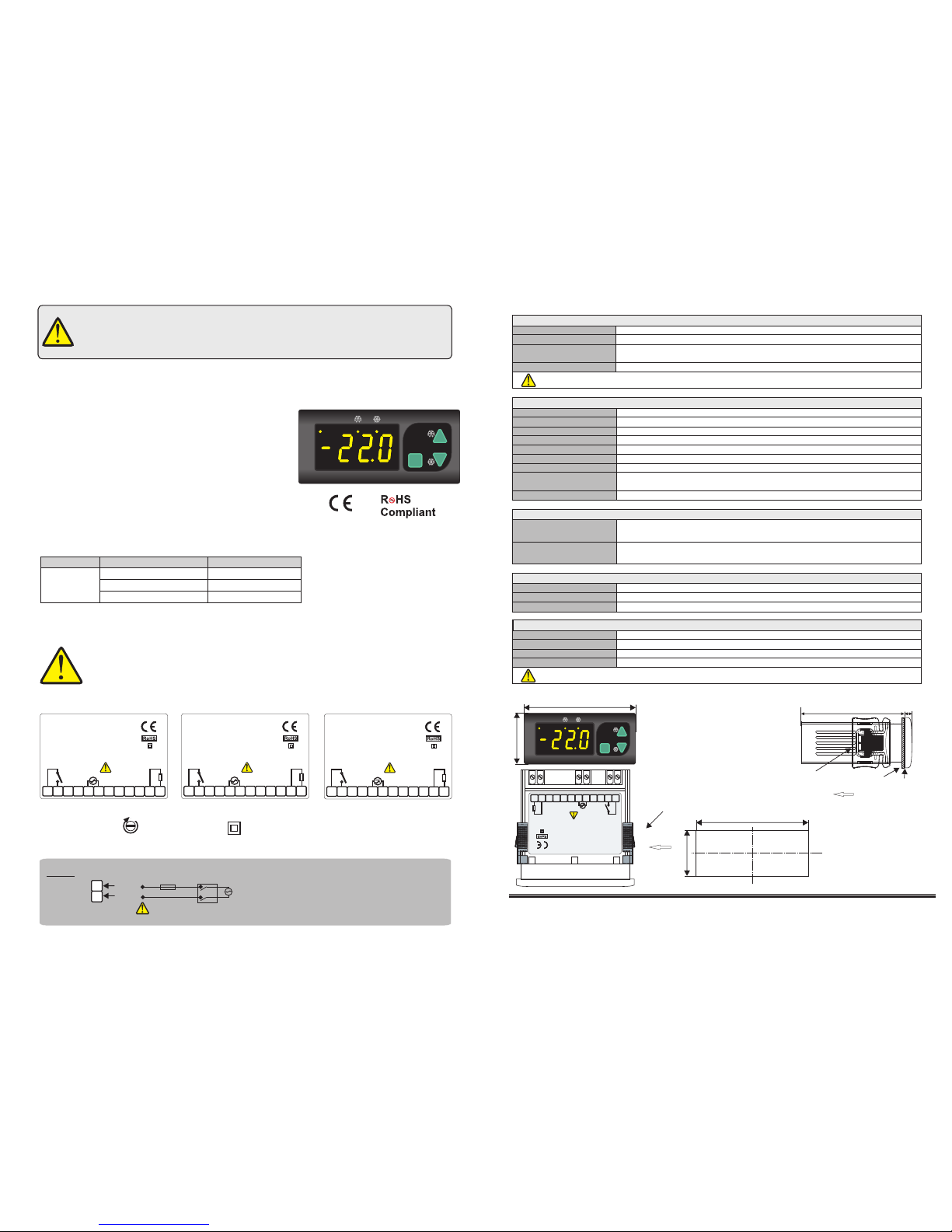
Connection Diagram
ENDA EDT1411 is intended for installation in control panels. Make sure that the device is used
only for intended purpose. The electrical connections must be carried out by a qualified staff
and must be according to the relevant locally applicable regulations. During an installation, all of the
cables that are connected to the device must be free of electrical power. The device must be
protected against inadmissible humidity, vibrations, severe soiling and make sure that the operation
temperature is not exceeded. The cables should not be close to the power cables or components.
1/3
SÝSEL MÜHENDÝSLÝK ELEKTRONÝK SAN. VE TÝC. A.Þ.
Yukarý Dudullu Barbaros Cad. Kutup Sok. No:20 34775 - ÜMRANÝYE/ÝSTANBUL/TURKEY
Tel : +90 216 499 46 64 Pbx. Fax : +90 216 365 74 01
url : www.enda.com.tr
Panel cut-out
Dimensions
Note :
1) Panel thickness
should be maximum
7 mm.
2) If there is no 60mm
free space at the back
side of the device, it
would be difficult to
remove it from the
Panel.
EDT1411P-E-01-R
Holding screw
0.4-0.5Nm.
Equipment is protected throughout
by DOUBLE INSULATION
71mm
29mm
Flush mounting
clamp
For removing mounting clamps:
Push the flush-mounting
clamp in direction 1 as shown
in the figure below. Then, pull
out the clamp in direction 2.
1
While cleaning the device, solvents (thinner, benzine, acid etc.) or corrosive materials must not be used.
4
5
SUPPLY:
NOTE:
184-253V AC
50/60Hz 4VA
Line
Neutral
230V AC
Supply
Switch
Note:
Cable size: 1,5mm²
Fuse
F 100 mA
250V AC
Fuse should
be connected
1) Mains supply cords shall meet the requirements of
IEC 60227 or IEC 60245.
2) In accordance with the safety regulations, the power
supply switch shall bring the identification of the
relevant instrument and it should be easily
accessible by the operator.
Ple
a
s
e re
ad
th
is
d
oc
u
me
nt
c
ar
e
f
u
ll
y be
fo
re
us
in
g
th
is
p
rod
uc
t
.
T
h
e g
ua
ran
te
e w
ill be
in
va
li
da
te
d
if
the
d
e
vi
ce
is
da
mag
ed
by
no
t fo
ll
ow
in
g
in
s
t
ruc
tio
n
s
de
ta
il
ed in
t
he
man
ua
l. Th
e c
omp
a
ny
s
h
a
ll
n
ot
b
e
r
es
po
n
sib
le
f
or
an
y
da
m
ag
e
or
lo
ss
e
s
ho
we
v
e
r
cau
se
d,
w
h
ic
h
may
b
e
e
xpe
ri
e
n
ce
d
as
a
re
su
lt
of th
e
in
st
al
la
ti
on
or use
of t
h
is
p
ro
du
ct.
Flush mounting
clamp
Depth
Panel
2
71mm
5mm
Rubber
packing
35mm
77mm
SET
SET
EDT1411
ENDA
°F
°C
Order Code
Output
Supply Voltage
EDT1411-NTC-230P
Röle -16A
230V AC +%10 -%20
24V AC %10±
EDT1411-NTC-24P
9-24V AC/DC %10±
EDT1411-NTC-12P
* 35 x 77mm sized.
* On-Off control.
* Single contact output for cooling control.
* Single NTC probe input.
* Offset value can be entered for NTC probe.
* Compressor protection parameters can be entered.
* In the case of probe failure, output state can be
selected on, off or periodical running.
* Upper and lower limits of the setpoint can be adjusted.
* Defrosting duration and interval can be adjusted.
* Temperature unit can be selected °C or °F.
* Upper and lower limits of the alarm value can be adjusted depending on the setpoint value.
* CE marked according to European Norms.
SET
SET
EDT1411
ENDA
°F
°C
SN: XXXXXXXXX
1 2 3 4 5 6
7 8 9
10
11 12
EDT1411-NTC-230VAC-P
DIGITAL DEFROST THERMOSTAT
ENDA INDUSTRIAL ELECTRONICS
230V AC +10% -20%
50/60Hz 4VA
COMPRESSOR
240V AC 16A
RESISTIVE LOAD
NTC
SENSOR
SN: XXXXXXXXX
1 2 3 4 5 6
7 8 9
10
11 12
EDT1411-NTC-24VAC-P
DIGITAL DEFROST THERMOSTAT
ENDA INDUSTRIAL ELECTRONICS
24V AC ±10%
50/60Hz 4VA
COMPRESSOR
240V AC 16A
RESISTIVE LOAD
NTC
SENSOR
SN: XXXXXXXXX
1 2 3 4 5 6
7 8 9
10
11 12
EDT1411-NTC-SM-P
DIGITAL DEFROST THERMOSTAT
ENDA INDUSTRIAL ELECTRONICS
COMPRESSOR
240V AC 16A
RESISTIVE LOAD
NTC
SENSOR
9-30V DC / 7-24V AC
10% 4VA±
SN: XXXXXXXXX
1 2 3 4 5 6
7 8 9
10
11 12
EDT1411-NTC-230VAC-P
DIGITAL DEFROST THERMOSTAT
ENDA INDUSTRIAL ELECTRONICS
230V AC +10% -20%
50/60Hz 4VA
COMPRESSOR
240V AC 16A
RESISTIVE LOAD
NTC
SENSOR
OUTPUT
COMPRESSOR
For EDT1411-NTC-XXP ; Relay: 240V AC, 8A (for resistive load), NO;
1 HP 230V AC CosF = 0.5 (for inductive load)
For EDT1411-NTC-XXP ; Mechanical 30.000.000 operation. (None load)
240V AC ,16A in the resistive load 30.000 operation.
Life expectancy for relay
Page 2

SET
SET
EDT1411
ENDA
°F
°C
While holding key COMPRESSOR setpoint value appears and by using and keys
the value can be adjusted.
Running Mode
Process
Value
-30.0
-29.9
-30.0
1000
If both keys are pressed and held for 3 seconds,
programming mode is entered.
-22.0
If both keys are pressed,
run mode is entered.
Used for adjusting the value of the setpoint in the run mode and for adjusting the selected parameter in the programming mode. While holding key, setpoint value of the selected parameter appears and by
using and keys the value can be adjusted.
When held down for 3 second in the run mode, manual defrost starts. After the specified time with D.dur parameter manual defrost finishes. When held down for 3 second manual defrost finishes before the
specified time ends. Used for selecting menu and increasing setpoint value of the parameters in the programming mode and for increasing the setpoint value in the run mode. When held down for a few
seconds, the change rate accelerates.
When held down for 3 second in the run mode continuous mode (*) starts. After the specified time with C.Con parameter this mode finishes. When held down for 3 second continuous mode finishes before
the specified time ends. Used for selecting parameters and decreasing the setpoint value in the programming mode and for decreasing the setpoint value in the run mode. When held down for a few seconds,
the change rate accelerates.
DEFROST
LED
COMPRESSOR
LED
FAHRENHEIT
LED
Displayed process value in the run mode, parameter name or value in programming mode.
SET
SET
SET
SET
A.lol
A.uPl
A.Set
A.dpo
The lower limit
of the setpoint.
Delay time for the compressor
after power is on.
Defrosting duration.
Limit for lower alarm level.
Limit for upper alarm level
Alarm configuration.
Energy was given the
message of alarm delayed
to show.
The upper limit
of the setpoint.
Delay time required for
compressor to restart following
a stop.
Compressor’s on the continuous
on mode length of stay.
Refrigeration differential
(hysteresis).
In the probe failure,compressor’s
output on duration.
Refrigeration
offset value.
Display resolution.
In the probe failure,compressor’s
output off duration.
D.dur
D.int
C.pon
C.ppn
C.Con
C.Fos
C.ppF
Interval between defrost
cycles.
Programming mode
R.lol
R.uPl
R.Hys
R.off
DrES
EDT1411P-E-01-R
Temperature unit.
Unit
During the defrosting
display configuration.
D.dsp
D.drE
Delay time for display real
temperature after defrost
is over.
Defrosting the process of
energy and the start of.
D.Pon
D.dPo
Defrosting’s delayed starting
after power is on.
A.dFl
Situation of alarm after the
were formed alarm message
delayed to show.
A.HYS
Alarm diffrerential
(hysteresis).
Security parameter for compressor
control menu.
Security parameter for defrosting
control menu.
Security parameter for alarm
control menu.
Security parameter for refrigeration
set value.
A.-re
A.-al
A.-de
A.-Cp
A.rE.S.
Security parameter for refrigeration
menu.
RE
CP
DE
Al
SE
2/3
S.Cod
Access code for security menu.This
parameter should be 321.
On the side on display at sight message,thermostat probe is short circuit or measured
temperature value is higher than the scale.
On the side on display at sight message, measured value is higher than the upper alarm
value.
Error Messages
On the side on display at sight message,measured value is lower than the lower alarm
value.
Alo
Ahi
Pfa
PsC
On the side on display at sight message,thermostat probe is broken or measured
temperature value is lower than the scale.
Page 3

EDT1411P-E-01-R
3/3
C.pon
C.FoS
C.PPn
C.PPF
Delay time for the compressor after power is on.
Delay time required for the compressor to restart following a stop.
In the probe failure.compressor’s output on duration.
In the probe failure,compressor’s output off duration.
0 255 min. 1
0 255 min. 0
C.Con
Compressor’s on the continuous on mode length of stay.
0 255 min. 0
0 255 min. 1
0.0 24.0 h. 0.1
Menu of Compressor control parameters
CP
Menu of Alarm control parameters
A.LoL
A.uPL
A.dFL
A.HYS
A.set
Alarm configuration (A.Abs = Absolute alarm. Alarm values are A.LoL and A.uPL.
A.rEF = Relative alarm. Alarm values are SET-A.LoL and SET+A.uPL.)
Limit for lower alarm level. When A.set is changed, should be readjusted.
Limit for upper alarm level. When A.set is changed, should be readjusted.
Alarm differential (hysteresis)
Situation of alarm after the were formed alarm message delayed to show.
-50.0 A.uPL °C -50.0
A.LoL 110.0 °C 110.0
0 255 min. 0
0.0 15.0 °C 2
A.AbS A.rEF A.AbS
A.dPo
Time delay to display alarm message after power is on.
Al
A. rEA. CP-
A. ALA.rE.S.
Security parameter for refrigeration menu
Security parameter for refrigeration setpoint value ( P.yes= Setpoint value is invisible.,P.no= Setpoint value is only visible.)
Security parameter for menu of compressor control
Security parameter for menu of defrost control
Security parameter for menu of alarm control
A. DE-
Menu of Parameter security
SE
R.HYS
R.LoL
R.uPL
R.oFF
Refrigeration differential(hysteresis)
The lower limit of the setpoint.
The upper limit of the setpoint.
The offset value for the refrigeration.
-50.0 °C -50R.uPL
-20.0 20.0 °C 0.0
MÝN MAX UNIT DEF.SET
Unit
Temperature unit
DrES
Display resolution (no= no decimal point , yes= with decimal point .)
°C °F °C
Yes
No
No
R.LoL 110.0 °C 110
Menu of Refrigeration control parameters
RE
Menu of Defrost control parameters
D.dur
D.int
D.dSP
D.drE
D.Pon
D.dPo
Defrosting duration.(If d.dur=0, then defrost is disable.)
Interval between defrost cycles.
Display configuration during defrost (rEAL= Real temperature is displayed during defrost.
def= During the defrosting on the display def message visible.)
Defrosting after power is on.(yes=Defrosting begins when power is on, no=Defrosting doesn’t begin when power is on.)
Delay time for defrosting after power is on.
Delay time for display real temperature after defrost is over.
0 255 1
1 120 1
REAL
def
Yes
def
No
No
0 30 min. 1
0 255 1
DE
min.
sec.
h.
min.
min.
sec.
= Menu is invisible.NonE
P.yes
P.no
= Parameters of menu are changeable.
= Parameters of menu are only visible.
If A.typ = A.rEF , then A.LoL = SET-ALoL & A.uPL = SET+A.uPL.
NOTE : Variables for lower and upper alarm level are determined according to A.SET parameter. If A.SET = A.AbS ,then A.LoL = A.LoL & A.uPL = A.uPL.
EDT1411 DEFROST CONTROLLED REFRIGERATION THERMOSTAT OUTPUT AND PARAMETER TABLE
Defrost
LED
Compressor
LED
Power
D.int
D.dPo
(Ifd.Pon = y
then d.dPo timer
runs)
D.dur
C.Pon
Compressor
OUT
C.Con
Continuous mode
Defrost mode
A.uPl
SET
A.uPl-A.HYS
SET+ r.HYS
A.LoL
A.LoL+A.HYS
A.dPo
A.dFL
Alarm
situation
AHi enable
AHi able dis
Alo enable
Alo able dis
0 23.5 hr. 0.3
0.1 20.0 °C 0.1
 Loading...