

Encore Networks VSR-30 Installation Manual

T
Revision C.1, May 2010
Document Part Number 15737.0001
Copyright 2010 Encore Networks, Inc.
All rights reserved.
encor
!
e
•
n
etworks
TM
VSR-30™ Installation Guide
his guide presents procedures for a standard installation of the VPN Satellite Router™ 30
(VSR-30) in the BANDIT family. (For information on the VSR-30 chassis, see the BANDIT
Products Hardware Reference Guide.)
Note: The VSR family includes the VSR-30 and the VSR-1200. For information on the VSR-1200
chassis, including installation, see the BANDIT II™, BANDIT III™, and VSR-1200™ Document
Set.)
Note: The screens shown in this document are examples; the choices shown on your VSR-30’s
menus depend on the features in the chassis and on the software version installed in the device.
(For figures, tables, and configurations not addressed in this VSR-30 Installation Guide, see the
BANDIT Products Software Configuration and Maintenance Guide or the BANDIT Products Hardware
Reference Guide.)
Gather all required information. Before you start these procedures, make sure you have all the
information required to set up the VSR-30 for use in your network—for example:
• The device’s IP address
•The device’s passwords
• The device’s VPN configuration, if any
• Interface requirements for the device’s ports
• Interface types for the ports—for example, DTE or DCE
• Interface protocols for the ports
• Network and routing functions that the device will perform
• Other pertinent network information
Use the site planning worksheets in the BANDIT Products Software Configuration and Maintenance
Guide as checklists for this information.
If you have questions or concerns after you have followed these procedures, contact Encore
Networks, Inc., at support@encorenetworks.com, 703-787-4625 (fax), or 703-318-4350 (voice).
Broadband Access Network Device for Intelligent Termination (BANDIT), BANDIT II, BANDIT III, BANDIT IP,
BANDIT Mini, BANDIT Plus, Encore Legacy-to-IP Operating System (ELIOS), FastCONNECT, IP Banking
Router 10 (IBR-10), IP Legacy Router 100 (ILR-100), Remote Data Unit (RDU), Selective Layer Encryption (SLE),
Virtual Broadband Redundancy System (VBRS), VPN Satellite Router 30 (VSR-30), and VPN Satellite Router 1200
(VSR-1200) are trademarks of Encore Networks, Inc. All other trademarks are the properties of their respective owners.
See the
BANDIT Products Software Configuration and Maintenance Guide for statements on Product Warranties
and on Limitation of Liability.
2 VSR-30™ Installation Guide
A Setting Up the Hardware
To install the VSR-30 in your network, do the following:
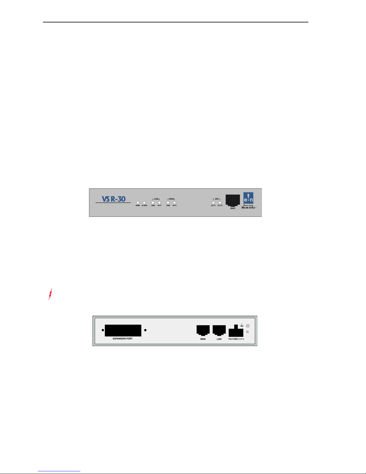
1 Unpack the chassis and components from the shipping box. Make sure you have all the
parts:
• the chassis (Figure 1)
• an autosensing external power supply
• an RJ-45 Supervisory cable
• an adapter for the Supervisory cable (described in the Note in Step 7)
• a paper copy of this Installation Guide
• any additional accessories that you ordered
Note: Shipments within North America include a power cable for an AC outlet. For
shipments outside North America, contact your distributor for a cable that meets local
requirements to connect the BANDIT’s power supply to a power outlet.
Figure 1. VSR-30 Chassis, Front
2 Place the VSR-30 chassis on a tabletop or shelf.
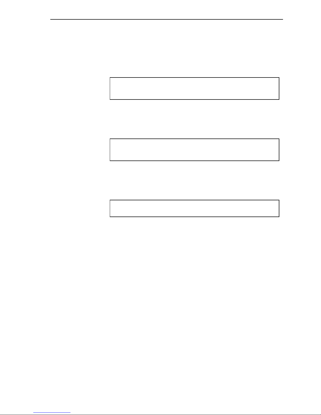
3 Connect an earth ground wire to the chassis, as follows: Attach a (minimum) 12 AWG
wire to the earth ground screw (next to the safety ground symbol), on the extreme right
rear or extreme left rear of the chassis (Figure 2). Use a ring terminal, such as an AMP
(part number 36160), for this connection.
Warning: An earth ground must connect to the chassis so that the device remains
grounded even when it is not receiving power.
Figure 2. VSR-30 Chassis, Rear
4 Connect the VSR’s ports to their network devices.
5 Connect the chassis to the external power supply.
6 Connect the external power supply to an outlet supplying 100–240 VAC at 47–63 Hz.
7 Use the Supervisory cable and adapter to connect the device’s Supervisory port to your
PC’s COM port.

VSR-30™ Installation Guide 3
Note: An eight-pin modular (RJ-45) to DB-9 adapter is the standard adapter to connect
the Supervisory cable to a PC. This adapter is shipped with the unit. The following
alternate adapters are also available. (Contact Encore Networks, Inc., if you need either
of these adapters.)
• An RJ-45 to DB-25 adapter for connection to most asynchronous terminals
• An RJ-45 to DB-25 modem adapter to connect a modem, for out-of-band management
or remote configuration
B Wireless Support
If you ordered a CDMA or GSM wireless card with the VSR-30, you need to set up the card
for use in the carrier network. And, if you wish to change the default settings for wireless
access, you need to reconfigure the wireless port.
In addition, a GSM wireless card must hold the appropriate Subscriber Identity Module
(SIM) for access to the carrier’s GSM wireless network.
To configure the device for wireless use, see the BANDIT Products Wireless Access Guide.
C Logging In
1 On the PC, open a terminal-emulation session, such as HyperTerminal. Use the settings
in Table 1 to establish communication between the terminal console and the VSR.
Table 1. Supervisory Port Communication Settings
Parameter Value
Bits per second 9600
Data bits 8
Parity None
Stop bit 1
Flow control Hardware
2 On the terminal console, press Enter to connect to the attached device.
❖ After successful log-in, the Main Menu appears.

4 VSR-30™ Installation Guide
D Using the Main Menu
The Main Menu is displayed when you log onto the VSR. From the Main Menu, you can
configure and operate the VSR.
Main Menu
----------
1) QuickStart Config Builder
2) Typical Configurations
3) Advanced Configurations
4) Tools
V) View Current Unit Status
L) Load Factory Defaults
P) Load Plug and Play Defaults
W) Write Configuration
R) Reset Unit
X) eXit Session
S) Statistics
Y) sYstem Administration
Enter Choice :
Note: Whenever you wish to return to a higher level in the VSR menus, press Escape.
Caution: The Supervisory connection to the device will time out after five (5) minutes
!
of console inactivity. If you have changed the device’s configuration and wish to use the
new configuration, save (write) the configuration before you leave the console. (See
Section F, Saving (Writing) the Device’s Configuration.)
1 On the Main Menu, do one of the following:
a To set up a basic configuration of the VSR for your network, select QuickStart Config
Builders.
❖ The Startup Config Options menu is displayed. (On the next menu—the Startup
Configuration Scenarios menu—you can enter basic information; the VSR will use this
information to build a standard configuration.) Go to Section E.1, Startup Configuration.
Startup Config Options
-----------------------
1) SATELLITE
Enter Choice :

VSR-30™ Installation Guide 5
b To configure specific features, select Advanced Configurations.
❖ The Advanced Configurations menu is displayed. You configure most parameters of
the VSR from this menu. Go to Section E, Configuring the Software.
Advanced Configurations
------------------------
1) Physical Configurations
2) Data Configurations
3) Local Address
4) Routing
5) Global Paths
Enter Choice :
E Configuring the Software
For a standard, basic configuration of the VSR for your network, see Section E.1, Startup
Configuration. For configuration of specific features, see the following sections.
• Section E.1, Startup Configuration
• Section E.2, Device Addresses
• Section E.3, Ports
• Section E.4, Virtual Private Network Connections
• Section E.5, IP Configuration
• Section E.6, Simple Network Management Protocol
E.1 Startup Configuration
The menu provides several templates for configurations that your network may use. You can
select a template (also known as a startup scenario), change the scenario’s IP addresses and
related information to reflect the values in your network, and load the scenario into the VSR.
Note: If you want the device to keep the configured scenario, be sure to write (save) the
configuration and reset the device.
To configure a basic setup for this device in your network, do the following:
1 On the Main Menu, select QuickStart Config Builders.
2 On the Startup Config Options menu, select the set of configuration templates.
❖ The menu for Startup Configuration Scenarios appears.

6 VSR-30™ Installation Guide
VSR-30
Startup Configuration Scenarios
---------------------------------------
1) Ethernet WAN SLE Gateway(Initiator)
2) Ethernet WAN SLE Gateway(Initiator) With Dial Backup
3) Ethernet WAN SLE Gateway(Terminator)
4) Ethernet WAN SLE Gateway(Terminator) With Dial Backup
Enter Choice :
3 Select one of the listed set-ups.
❖ The menu for the selected set-up (scenario) is displayed. (The menu shown is for an
Ethernet WAN SLE Gateway, Initiator.)
VSR-30
Startup Configuration Parameters
---------------------------------
1) System Name :
2) LAN Interface IP : 0.0.0.0 /0.0.0.0 No DHCP Server
3) LAN Private NAT IP : 0.0.0.0 /0.0.0.0 masq:0.0.0.0
4) WAN Interface IP : Dynamic
5) Primary DNS Server : 0.0.0.0
6) VPN Gateway :
7) VPN User ID :
8) VPN Pre-Shared Key :
9) Application Clients IP : 0.0.0.0
L) Load Above Config
V) reView/Modify Loaded Config
R) Reset (Write and Reset)
Z) Clear All Fields
Enter Choice :
Note: At this point, all IP addresses, etc., have null values. Before you can load the
configuration into the VSR, you must enter values that reflect your network’s settings.
4 For each item (parameter) in the menu, do the following:
a Select the item (for example, WAN Interface IP).
Enter IP Address :
b Type a value for the item, and press Enter.
c If the item requests additional information, enter that information.
❖ When the item has been configured, the scenario’s menu is displayed again.
VSR-30™ Installation Guide 7
5 After you have performed Step 4 for each item (parameter) in the menu, do one of the
following:
a Select Load Above Config.
❖ The following prompt asks for confirmation. Go to Step 6.
Caution: Existing configurations will be over written
Do you want to Continue?(Y/N)[N]:
b Select Reset (Load, Write and Reset).
❖ The following prompt asks for confirmation. Go to Step 6.
Caution: Existing configurations will be over written
Do you want to Continue?(Y/N)[N]:
c Select Clear All Fields.
❖ The following prompt asks for confirmation.
This Clears All the above Fields, Continue?(Y/N)[N]:
• Do one of the following:
◆ If you wish to reconfigure, enter Y.
❖ All fields in the menu are reset to null values. Return to Step 4.
◆ If you do not wish to reconfigure, press Escape to return to the Startup
Configuration Scenarios menu.
❖ The configuration retains the settings you have entered, but they are not yet in use.
Return to Step 4.
6 To load the new configuration, enter y.
❖ The configuration is loaded into the VSR.
Note: When you write (save) a configuration entered on the Quickstart menu, other
required settings are updated automatically. For example, when you enter the device’s
IP address, a path is automatically set up in the IP routing table to direct this IP
address to the device’s LAN port.
❖ If you selected Reset (Load, Write, and Reset), the configuration is also saved. This
makes the configuration permanent (unless you change it again). Then the device resets.
7 When the configuration has finished loading, press Escape until you return to the Main
Menu. (Go to Section D, Using the Main Menu.)

8 VSR-30™ Installation Guide
8 To save the configured scenario (if it has not already been saved), do the following:
a Write the configuration. (See Section F, Saving (Writing) the Device’s Configuration.)
b Reset the device. (Section G, Restarting (Resetting) the Device.)
E.2 Device Addresses
To configure the device’s addresses, do the following:
1 On the Advanced Configurations menu, select Local Addresses.
BANDIT Plus
Configure Local Addresses
----------------------------
1) IP Address : 192.168.169.1
2) BANDIT Name : BANDIT Plus
Enter Choice :
2 On the Configure Local Addresses menu, select IP Address.
3 Enter the device’s IP address and press Enter. (Get the device’s IP address from your
network administrator.)
4 Select BANDIT Name.
5 Enter a unique name to identify this device in your network, and press Enter.
E.3 Ports
To configure software for the device’s ports, do the following:
1 On the Advanced Configurations menu, select Data Configuration.
❖ The Logical Port Protocol menu is displayed. (Table 2 lists the Line IDs for the ports.)
Table 2. Port Identifiers
Line ID Physical (Hardware) Port Default Software Configuration
C COM/Supervisor port Comm/Supervisor
L Ethernet LAN port Ethernet
W Ethernet WAN port Ethernet
EExpansion port
b
P More ports
(See Step 2.)
a
a. Do not modify the configuration for the Comm/Supervisor port.
b. These are virtual Logical Ports. A protocol configured on a Logical Port can be
associated with a global path, which is turn is associated with a physical port. (See
Section E.3.1, Protocols. For information on global paths, see the BANDIT Products
Software Configuration and Maintenance Guide.)
 Loading...