

Page 1

T
Revision I.2, April 2009
Document Part Number 14973.1001
Copyright 2009 Encore Networks, Inc.
All rights reserved.
encor
!
e
•
n
etworks
TM
BANDIT™, BANDIT IP™, and BANDIT
Plus™ Installation Guide
for ELIOS™ Software Version 0600
his guide presents procedures for a standard installation of the Broadband Access Network
Device for Intelligent Termination™ (BANDIT™).
Note: Except where otherwise specified, this document’s procedures apply to the following
models of the BANDIT™ chassis: the original BANDIT™, the BANDIT IP™, and the
BANDIT Plus™. In addition, the screens shown in this document are examples; the choices
shown on your BANDIT’s menus depend on the features in the chassis and on the software
version installed in the device. (For figures, tables, and configurations not addressed in this
Installation Guide, see the BANDIT Products Software Configuration and Maintenance Guide or the
BANDIT Products Hardware Reference Guide.)
Gather all required information. Before you start these procedures, make sure you have all the
information required to set up the BANDIT for use in your network—for example:
• The device’s IP address
•The device’s passwords
• The device’s VPN configuration, if any
• Interface requirements for the device’s ports
• Interface types for the ports—for example, DTE or DCE
• Interface protocols for the ports
• Network and routing functions that the device will perform
• Other pertinent network information
Use the site planning worksheets in the BANDIT Products Software Configuration and Maintenance
Guide as checklists for this information.
If you have questions or concerns after you have followed these procedures, contact Encore
Networks, Inc., at [email protected], 703-787-4625 (fax), or 703-318-4350 (voice).
Broadband Access Network Device for Intelligent Termination (BANDIT), BANDIT II, BANDIT III, BANDIT IP,
BANDIT Mini, BANDIT Plus, Encore Legacy-to-IP Operating System (ELIOS), FastCONNECT, IP Banking
Router 10 (IBR-10), IP Legacy Router 100 (ILR-100), Remote Data Unit (RDU), Selective Layer Encryption (SLE),
Virtual Broadband Redundancy System (VBRS), VPN Satellite Router 30 (VSR-30), and VPN Satellite Router 1200
(VSR-1200) are trademarks of Encore Networks, Inc. All other trademarks are the properties of their respective owners.
See the
BANDIT Products Software Configuration and Maintenance Guide for statements on Product Warranties
and on Limitation of Liability.
Page 2

2 BANDIT™, BANDIT IP™, and BANDIT Plus™ Installation Guide
A Plug-and-Play Mode
The BANDIT IP comes as a plug-and-play device so that it can be up and running quickly in
standard installations. (The other products in the BANDIT family come with factory default
settings. If you wish, you can change any unit to plug-and-play mode, save the
configuration, and restart the unit.)
In plug-and-play mode, a BANDIT product is a DHCP client on the WAN (internet) port,
and is a DHCP server on the LAN (intranet) port. When a BANDIT powers up in plug-andplay mode, it is assigned its public IP address by the WAN's DHCP server. (Typically, the
WAN's DHCP server is a device maintained by your internet service provider, or ISP.) Then
the BANDIT product, as the local DHCP server, assigns private IP addresses to DHCP clients
on the local network. (The BANDIT’s DHCP server has a default IP address pool, which can
be changed.)
Warning: If your network already has a DHCP server, disable the BANDIT IP's plugand-play mode before you connect the BANDIT IP to the network. Otherwise, there will
be contention between the DHCP servers.
A.1 Using Plug-and-Play Mode
To use the BANDIT IP’s plug-and-play features, do the following:
1 Follow the instructions for installing the hardware, as described in Section B, Setting Up
the Hardware.
2 Boot up the BANDIT, as described in Section D, Logging In.
Note: After logging in, you may wish to review the LAN port's settings. See Section F.3.2,
DHCP Settings.
A.2 Disabling Plug-and-Play Mode
To disable the BANDIT IP’s plug-and-play features, do the following:
1 Follow the instructions for installing the hardware (but do not connect the BANDIT
ports to the network devices). See Section B, Setting Up the Hardware.
2 Then boot up the BANDIT device. See Section D, Logging In.
3 In the Main Menu, select Load Factory Defaults. Then select Write, then Reset. See the
following sections:
• Section E, Using the Main Menu
• Section G, Saving (Writing) the Device’s Configuration
• Section H, Restarting (Resetting) the Device
4 After the device restarts, select Typical Configurations. See Section E, Using the Main
Menu.
5 In the Typical Configurations menu, select the LAN port and review its settings. See
Section F.3, Ports.
Page 3

BANDIT™, BANDIT IP™, and BANDIT Plus™ Installation Guide 3
6 When you have verified that the device’s default factory configuration matches your
needs (or when you have changed the configuration as needed), save the configuration.
See the following sections:
• Section F, Configuring the Software
• Section G, Saving (Writing) the Device’s Configuration
7 Connect the BANDIT's WAN and LAN ports to the networks.
8 Then connect the BANDIT’s modem port, serial port, and expansion port to the devices
the BANDIT will use.
9 Reset the BANDIT, as described in Section H, Restarting (Resetting) the Device.
10 If, at any time, you wish to exit the BANDIT session, see Section I, Exiting a Session.
B Setting Up the Hardware
The BANDIT is available in the following models: the original BANDIT, the BANDIT IP, and
the BANDIT Plus. (For information on product models, see the BANDIT Products Hardware
Reference Guide.)
1 Unpack the chassis and components from the shipping box. Make sure you have all the
parts:
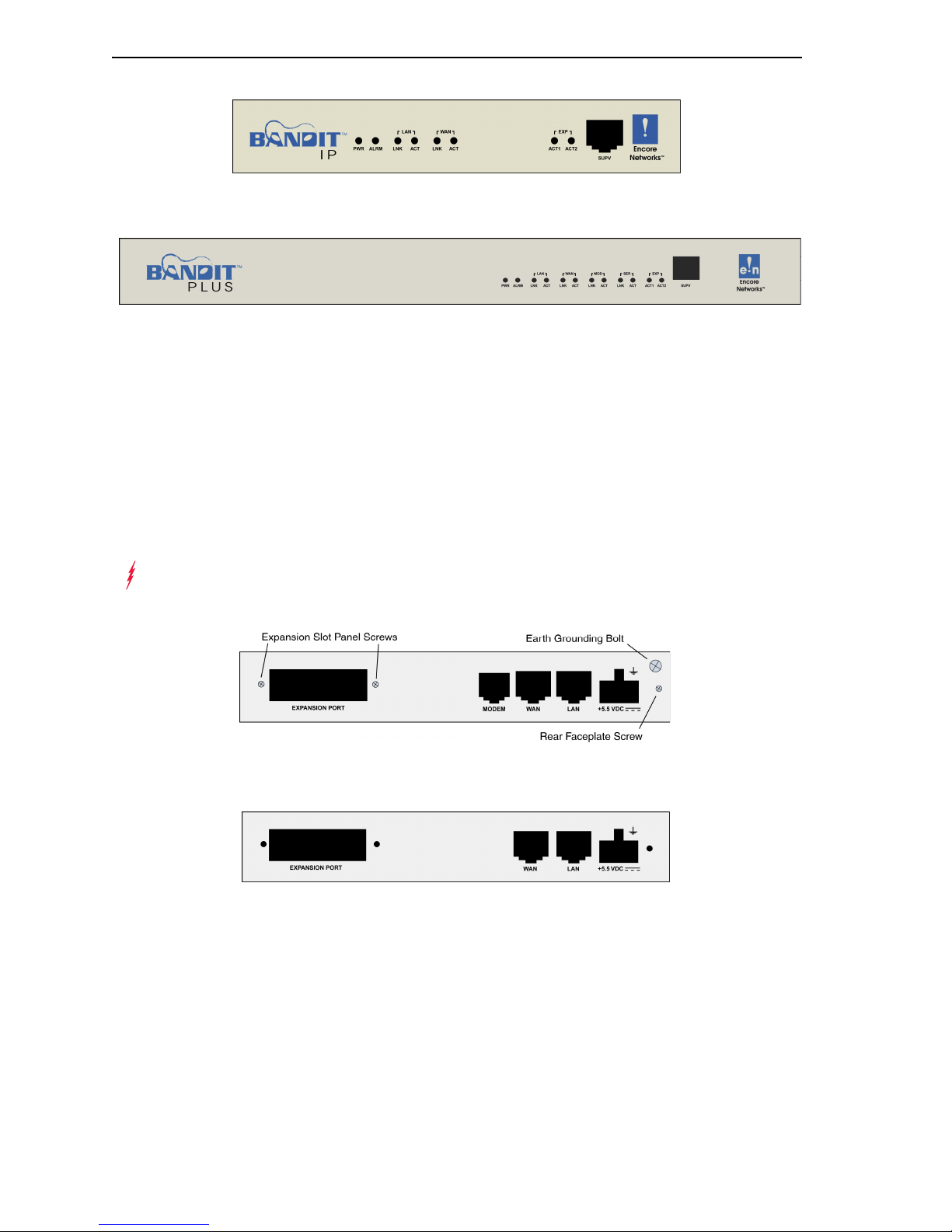
• the chassis (Figure 1 through Figure 3)
• an autosensing external power supply (only for the BANDIT IP or the original
BANDIT)
• an RJ-45 Supervisory cable
• an adapter for the Supervisory cable (described in the Note in Step 9)
• an RJ-11 modem cable (only for the original BANDIT or the BANDIT Plus)
• a paper copy of this Installation Guide
• any additional accessories that you ordered
Note: Shipments within North America include a power cable for an AC outlet. For
shipments outside North America, contact your distributor for a cable that meets local
requirements to connect the BANDIT’s power supply to a power outlet.
Note: If you wish to view or download the customer documentation for the BANDIT
products, visit the following site:
www.encorenetworks.com/support/documentation/voice_data/broadband.htm
Contact your Encore Networks sales representative if you wish to order a CD
containing BANDIT documentation.
Figure 1. Original BANDIT Chassis, Front
Page 4
4 BANDIT™, BANDIT IP™, and BANDIT Plus™ Installation Guide
Figure 2. BANDIT IP Chassis, Front
Figure 3. BANDIT Plus Chassis, Front
2 Do one of the following:
a Place the original BANDIT or BANDIT IP chassis on a tabletop or shelf.
b Mount the BANDIT Plus chassis in an equipment rack.
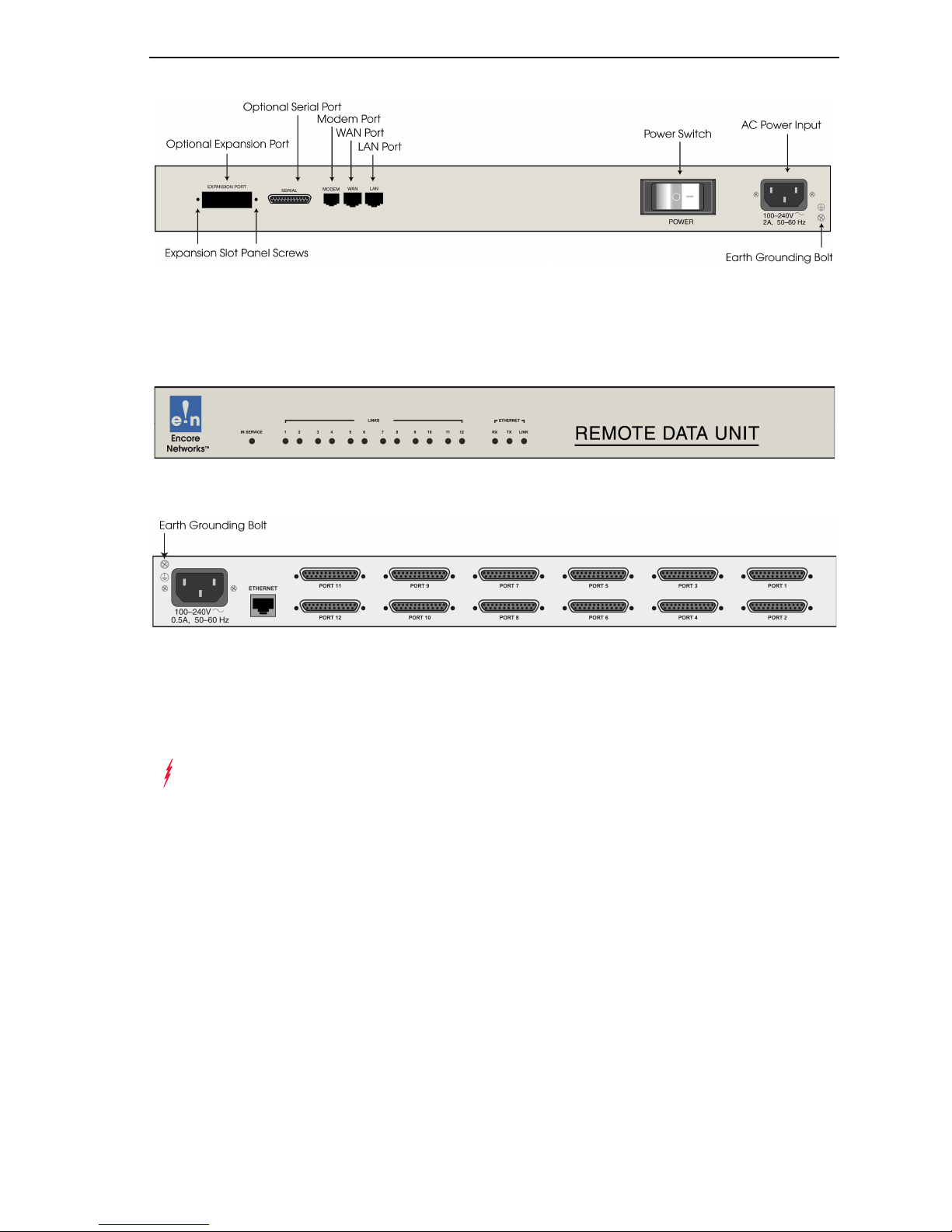
3 Connect an earth ground wire to the chassis, as follows: Attach a (minimum) 12 AWG
wire to the earth ground screw (next to the safety ground symbol), on the extreme right
rear or extreme left rear of the chassis (Figure 4 through Figure 6). Use a ring terminal,
such as an AMP (part number 36160), for this connection.
Warning: An earth ground must connect to the chassis so that the device remains
grounded even when it is not receiving power.
Figure 4. Original BANDIT Chassis, Rear
Figure 5. BANDIT IP Chassis, Rear
Page 5
BANDIT™, BANDIT IP™, and BANDIT Plus™ Installation Guide 5
Figure 6. BANDIT Plus Chassis, Rear
4 If this is a BANDIT Plus, and if it uses a Remote Data Unit™ (RDU, Figure 7), connect
the BANDIT Plus’s Ethernet LAN port (Figure 6) to the RDU’s Ethernet port (Figure 8).
Figure 7. Remote Data Unit, Front
Figure 8. Remote Data Unit, Rear
5 Connect the BANDIT’s ports to their network devices. For example, on the original
BANDIT, connect the LAN port, WAN port, modem port, serial port, and expansion
port to the network devices.
Warning: Do not connect the ports to the network devices if you need to disable the
BANDIT IP’s plug-and-play mode.
6 If an RDU is connected to the BANDIT Plus, connect the RDU’s serial ports to their
network devices.
7 If you are setting up the BANDIT IP or the original BANDIT: Connect the chassis to the
external power supply.
8 Do one of the following:
a For the BANDIT IP or original BANDIT: Connect the external power supply to an outlet
supplying 100–240 VAC at 47–63 Hz.
b For the BANDIT Plus: Connect the chassis to an outlet supplying 100–240 VAC at 47–
63 Hz.
9 Use the Supervisory cable and adapter to connect the device’s Supervisory port to your
PC’s COM port.
Page 6

6 BANDIT™, BANDIT IP™, and BANDIT Plus™ Installation Guide
Note: An eight-pin modular (RJ-45) to DB-9 adapter is the standard adapter to connect
the Supervisory cable to a PC. This adapter is shipped with the unit. The following
alternate adapters are also available. (Contact Encore Networks, Inc., if you need either
of these adapters.)
• An RJ-45 to DB-25 adapter for connection to most asynchronous terminals
• An RJ-45 to DB-25 modem adapter to connect a modem, for out-of-band management
or remote configuration
10 If you need to disable the BANDIT IP’s plug-and-play mode, see Section A.2, Disabling
Plug-and-Play Mode. Then connect the BANDIT IP’s ports to their network devices.
C Wireless Support
If you ordered a CDMA or GSM wireless card with the BANDIT device, you need to set up
the card for use in the carrier network. And, if you wish to change the default settings for
wireless access, you need to reconfigure the wireless port.
In addition, a GSM wireless card must hold the appropriate Subscriber Identity Module
(SIM) for access to the carrier’s GSM wireless network.
To configure the BANDIT device for wireless use, see the BANDIT Products Wireless Access
Guide.
D Logging In
1 On the PC, open a terminal-emulation session, such as HyperTerminal. Use the settings
in Table 1 to establish communication between the terminal console and the BANDIT.
Table 1. Supervisory Port Communication Settings
Parameter Value
Bits per second 9600
Data bits 8
Parity None
Stop bit 1
Flow control Hardware
2 On the terminal console, press Enter to connect to the attached device.
❖ After successful log-in, the Main Menu appears.
Page 7

BANDIT™, BANDIT IP™, and BANDIT Plus™ Installation Guide 7
E Using the Main Menu
The Main Menu is displayed when you log onto the BANDIT. From the Main Menu, you can
configure and operate the BANDIT.
Main Menu
----------
1) QuickStart Config Builder
2) Typical Configurations
3) Advanced Configurations
4) Tools
V) View Current Unit Status
L) Load Factory Defaults
P) Load Plug and Play Defaults
W) Write Configuration
R) Reset Unit
X) eXit Session
S) Statistics
Y) sYstem Administration
Enter Choice :
Note: Whenever you wish to return to a higher level in the BANDIT menus, press
Escape.
Caution: The Supervisory connection to the device will time out after five (5) minutes
!
of console inactivity. If you have changed the device’s configuration and wish to use the
new configuration, save (write) the configuration before you leave the console. (See
Section G, Saving (Writing) the Device’s Configuration.)
1 On the Main Menu, do one of the following:
a To disable the BANDIT IP’s plug-and-play mode, select Load Factory Defaults.
❖ The BANDIT’s settings for plug-and-play mode are replaced by a configuration that
you can customize for your site. Perform the procedures in Section G, Saving (Writing)
the Device’s Configuration, and Section H, Restarting (Resetting) the Device. Then select
Step 1b or Step 1c in this current procedure.
b To set up a basic configuration of the BANDIT for your network, select QuickStart
Config Builders.
❖ The Startup Config Options menu is displayed. (On the next menu—the Startup
Configuration Scenarios menu—you can enter basic information; the BANDIT will use
this information to build a standard configuration.) The Banking configuration is used
for financial networks. Select Satellite if most of the transmissions will travel over
satellite networks. For other networks, use Generic. Go to Section F.1, Startup
Configuration.
Page 8

8 BANDIT™, BANDIT IP™, and BANDIT Plus™ Installation Guide
Startup Config Options
-----------------------
1) GENERIC
2) BANKING
Enter Choice :
c To configure specific features, select Advanced Configurations.
❖ The Advanced Configurations menu is displayed. You configure most parameters of
the BANDIT from this menu. Go to Section F, Configuring the Software.
Advanced Configurations
------------------------
1) Physical Configurations
2) Data Configurations
3) Local Address
4) Routing
5) Global Paths
Enter Choice :
F Configuring the Software
For a standard, basic configuration of the BANDIT for your network, see Section F.1, Startup
Configuration. For configuration of specific features, see the following sections.
• Section F.1, Startup Configuration
• Section F.2, Device Addresses
• Section F.3, Ports
• Section F.4, Virtual Private Network Connections
• Section F.5, IP Configuration
• Section F.6, Simple Network Management Protocol
F.1 Startup Configuration
The menu provides several templates for configurations that your network may use. You can
select a template (also known as a startup scenario), change the scenario’s IP addresses and
related information to reflect the values in your network, and load the scenario into the
BANDIT.
Note: If you want the device to keep the configured scenario, be sure to write (save) the
configuration and reset the device.
To configure a basic setup for this device in your network, do the following:
1 On the Main Menu, select QuickStart Config Builders.
Page 9

BANDIT™, BANDIT IP™, and BANDIT Plus™ Installation Guide 9
2 On the Startup Config Options menu, select the Generic set of configuration templates.
❖ The menu for Startup Configuration Scenarios appears.
BANDIT
Startup Configuration Scenarios
---------------------------------------
1) PPPoE WAN Router
2) PPPoE WAN VPN Gateway(Initiator)
3) PPPoE WAN VPN Gateway(Initiator) With Dial Backup
4) PPPoE WAN VPN Gateway(Terminator)
5) PPPoE WAN VPN Gateway(Terminator) With Dial Backup
6) Ethernet WAN Router
7) Ethernet WAN VPN Gateway(Initiator)
8) Ethernet WAN VPN Gateway(Initiator) With Dial Backup
9) Ethernet WAN VPN Gateway(Terminator)
A) Ethernet WAN VPN Gateway(Terminator) With Dial Backup
Enter Choice :
3 Select one of the listed set-ups.
❖ The menu for the selected set-up (scenario) is displayed. (The menu shown is for a
PPPoE WAN VPN Gateway, Initiator.)
Startup Configuration Parameters
---------------------------------
1) System Name :
2) LAN Interface IP : 0.0.0.0 /0.0.0.0
3) LAN Private NAT IP : 0.0.0.0 /0.0.0.0 masq:0.0.0.0
4) WAN Interface IP : Dynamic
5) PPPoE User Name :
6) PPPoE Password :
7) Primary DNS Server : 0.0.0.0
8) VPN Gateway :
9) VPN User ID :
A) VPN Pre-Shared Key :
B) Remote Subnet : 0.0.0.0/0.0.0.0
L) Load Above Config
R) Reset (Load, Write and Reset)
Z) Clear All Fields
Enter Choice :
Note: At this point, all IP addresses, etc., have null values. Before you can load the
configuration into the BANDIT, you must enter values that reflect your network’s
settings.
Page 10

10 BANDIT™, BANDIT IP™, and BANDIT Plus™ Installation Guide
4 For each item (parameter) in the menu, do the following:
a Select the item (for example, WAN Interface IP).
Enter IP Address :
b Type a value for the item, and press Enter.
c If the item requests additional information, enter that information.
❖ When the item has been configured, the scenario’s menu is displayed again.
5 After you have performed Step 4 for each item (parameter) in the menu, do one of the
following:
a Select Load Above Config.
❖ The following prompt asks for confirmation. Go to Step 6.
Caution: Existing configurations will be over written
Do you want to Continue?(Y/N)[N]:
b Select Reset (Load, Write and Reset).
❖ The following prompt asks for confirmation. Go to Step 6.
Caution: Existing configurations will be over written
Do you want to Continue?(Y/N)[N]:
c Select Clear All Fields.
❖ The following prompt asks for confirmation.
This Clears All the above Fields, Continue?(Y/N)[N]:
• Do one of the following:
◆ If you wish to reconfigure, enter Y.
❖ All fields in the menu are reset to null values. Return to Step 4.
◆ If you do not wish to reconfigure, press Escape to return to the Startup
Configuration Scenarios menu.
❖ The configuration retains the settings you have entered, but they are not yet in use.
Return to Step 4.
Page 11

BANDIT™, BANDIT IP™, and BANDIT Plus™ Installation Guide 11
6 To load the new configuration, enter y.
❖ The configuration is loaded into the BANDIT.
Note: When you write (save) a configuration entered on the Quickstart menu, other
required settings are updated automatically. For example, when you enter the device’s
IP address, a path is automatically set up in the IP routing table to direct this IP
address to the device’s LAN port.
❖ If you selected Reset (Load, Write, and Reset), the configuration is also saved. This
makes the configuration permanent (unless you change it again). Then the device resets.
7 When the configuration has finished loading, press Escape until you return to the Main
Menu. (Go to Section E, Using the Main Menu.)
8 To save the configured scenario (if it has not already been saved), do the following:
a Write the configuration. (See Section G, Saving (Writing) the Device’s Configuration.)
b Reset the device. (Section H, Restarting (Resetting) the Device.)
F.2 Device Addresses
To configure the device’s addresses, do the following:
1 On the Advanced Configurations menu, select Local Addresses.
BANDIT Plus
Configure Local Addresses
----------------------------
1) IP Address : 192.168.169.1
2) BANDIT Name : BANDIT Plus
Enter Choice :
2 On the Configure Local Addresses menu, select IP Address.
3 Enter the device’s IP address and press Enter. (Get the device’s IP address from your
network administrator.)
4 Select BANDIT Name.
5 Enter a unique name to identify this device in your network, and press Enter.
F.3 Ports
To configure software for the device’s ports, do the following:
1 On the Advanced Configurations menu, select Data Configuration.
❖ The Logical Port Protocol menu is displayed. (Table 2 lists the Line IDs for the ports.)
Page 12

12 BANDIT™, BANDIT IP™, and BANDIT Plus™ Installation Guide
Table 2. Port Identifiers
Line ID Physical (Hardware) Port Default Software Configuration
a
C COM/Supervisor port Comm/Supervisor
M Modem port Point to Point
L Ethernet LAN port Ethernet (DHCP Server
192.168.101.1)
W Ethernet WAN port Ethernet (DHCP Client 0.0.0.0)
S Serial port Frame Relay
E Expansion port Frame Relay
B RDU ports (See Step 2.)
b
P More ports
a. Do not modify the configuration for the Comm/Supervisor port.
b. These are virtual Logical Ports. A protocol configured on a Logical Port can be
associated with a global path, which is turn is associated with a physical port. (See
Section F.3.1, Protocols. For information on global paths, see the BANDIT Products
Software Configuration and Maintenance Guide.)
(See Step 2.)
2 On the Logical Port Protocol menu, select the physical port whose software
configuration you wish to modify.
❖ One of the following occurs:
• If you are configuring a physical port on the chassis, the Logical Port Attribute menu
appears. Go to Step 4.
• If you are configuring a physical port on an RDU, the RDU Logical Port Menu is
displayed. Continue to Step 3.
BANDIT Plus
Logical Port Protocol Attached To Port Interfaces
------------------------------------------------------------------------
1) UNDEFINED RDU Port 1
2) UNDEFINED RDU Port 2
3) UNDEFINED RDU Port 3
4) UNDEFINED RDU Port 4
5) UNDEFINED RDU Port 5
6) UNDEFINED RDU Port 6
7) UNDEFINED RDU Port 7
8) UNDEFINED RDU Port 8
9) UNDEFINED RDU Port 9
A) UNDEFINED RDU Port 10
B) UNDEFINED RDU Port 11
C) UNDEFINED RDU Port 12
Enter Port :
Page 13

BANDIT™, BANDIT IP™, and BANDIT Plus™ Installation Guide 13
• If you are configuring a virtual Logical Port, the Virtual Logical Port menu is
displayed. Continue to Step 3.
BANDIT Plus
Logical Port Protocol Mapped To Port Interfaces
------------------------------------------------------------------------
1) UNDEFINED
2) UNDEFINED
3) UNDEFINED
4) UNDEFINED
5) UNDEFINED
6) UNDEFINED
7) UNDEFINED
8) UNDEFINED
9) UNDEFINED
10) UNDEFINED
11) UNDEFINED
12) UNDEFINED
13) UNDEFINED
14) UNDEFINED
15) UNDEFINED
16) UNDEFINED
17) UNDEFINED
P) More Ports...
Enter Port :
3 On the RDU Port menu or the Virtual Logical Port menu, select the port to configure.
❖ The Logical Port Attribute menu appears.
4 To modify the port’s default settings, see the following:
• Section F.3.1, Protocols
• Section F.3.2, DHCP Settings (only for the WAN and LAN ports)
• Section F.3.3, Dial Backup Settings
F.3.1 Protocols
To change the protocol that a port uses, or to modify attributes of a port’s protocol, do the
following on the Logical Port Attribute menu (see Section F.3, Ports):
1 If you wish to change the protocol the port uses, do all of the following:
a Select Undefine Current Logical Port.
Note: The menu for the Modem port does not offer this selection.
b Select Protocol.
c On the Logical Port Protocol Selection menu, select the protocol you want this port to
use. Go to Step 2a.
2 To modify parameters in the port’s protocol, select Protocol.
❖ The protocols available for the port are displayed. (This example shows protocols for
a serial port. A serial port is available in models that support legacy protocols.)
Page 14

14 BANDIT™, BANDIT IP™, and BANDIT Plus™ Installation Guide
Logical Port Protocol Selection Menu
-------------------------------------
1) Frame Relay
2) Point-to-Point (PPP)
3) MultiLink PPP
4) X.25+
5) SDLC Routing
6) SDLC 1490 Configuration
7) Bit Sync Encapsulation
8) Asynchronous Encapsulation
9) Serial Line IP (SLIP)
A) Async Burroughs Poll/Select
B) Sync Burroughs Poll/Select
C) Bisync
D) Telnet Terminal
E) XXX PAD
Enter Choice :
a On the protocol configuration menu, select and change parameters to work in your
network.
b When you have finished configuring the protocol, press Escape to return to the Logical
Port Attribute menu.
F.3.2 DHCP Settings
To review settings that the WAN or LAN port uses for DHCP, or to modify or disable DHCP
on a port, do the following on the port’s Logical Port Attribute menu (see Section F.3, Ports).
Note: The WAN and LAN ports use different settings. Typically, a BANDIT device is a
DHCP client on the WAN port and is a DHCP server on the LAN port. You may enable,
modify, or disable use of DHCP on one port or on both ports.
1 Select DHCP Type.
❖ The DHCP Type menu appears.
DHCP Type
----------
1) Server
2) Client
3) None
Enter Choice :
Page 15

BANDIT™, BANDIT IP™, and BANDIT Plus™ Installation Guide 15
2 Select the option you want this port to use.
❖ If you select None, the device does not use this port for DHCP. Press Escape until you
return to the port’s Logical Port Attribute menu. Go to Step 5.
❖ If you select Client, the device uses this port to request its IP address. (On the WAN
port, the device requests its public IP address.) No further configuration is required for
the DHCP client role. Press Escape until you return to the port’s Logical Port Attribute
menu. Go to Step 5.
❖ If you select Server, the device uses this port to assign IP addresses. (On the LAN
port, the device assigns private IP addresses.) The Logical Port Attribute menu is
redisplayed, with a menu item for configuring the DHCP server.
3 Select DHCP Server Parameters.
❖ The DHCP Server Parameters menu appears.
DHCP SERVER PARAMETERS
----------------------------
1) Local DHCP Server IP Address (N.N.N.N):0.0.0.0
2) DHCP Pool IP Address Low (N.N.N.N) :0.0.0.0
3) DHCP Pool IP Address High (N.N.N.N) :0.0.0.0
4) DHCP Network Mask (N.N.N.N) :255.255.255.0
5) DHCP Lease Time (minutes) : 1440
6) Domain Name for DHCP clients:
7) Primary Router (N.N.N.N) :0.0.0.0
8) NETBIOS Server (N.N.N.N) :0.0.0.0
Enter the number of the item to change:
4 Select and configure each parameter the device will use as the local (intranet) DHCP
server. When you have finished configuring the DHCP server, press Escape until you
return to the port’s Logical Port Attribute menu.
5 When you have finished configuring the port, press Escape until you return to the Main
Menu.
6 Save the configuration and reset the device. See Section G, Saving (Writing) the Device’s
Configuration, and Section H, Restarting (Resetting) the Device.
F.3.3 Dial Backup Settings
1 To configure a port for dial backup, select Dialup Configuration on the Logical Port
Attribute menu (see Section F.3, Ports).
Note: A port can be configured for dial backup only if its protocol supports dial
backup. The port’s Logical Port Attribute menu will not allow this option unless the
protocol supports it. To select a protocol that supports dial backup, see Section F.3.1,
Protocols.
2 Configure the parameters for the dialup. When you have finished, press Escape to
return to the Logical Port Attribute menu.
Page 16

16 BANDIT™, BANDIT IP™, and BANDIT Plus™ Installation Guide
F.4 Virtual Private Network Connections
One of the principal features in the BANDIT family of products is the support of virtual
private networks (VPNs). This section discusses the configuration of VPNs in the BANDIT
products.
If any VPN connections will traverse satellite networks, the BANDIT uses Selective Layer
Encryption™ (SLE, patent pending). See Section F.4.3, Selective Layer Encryption in VPNs.
1 To configure VPN connections, do the following:
a On the Advanced Configurations menu, select Routing.
b On the Routing menu, select IP Routing.
c On the IP Routing Configuration menu, select IP/VPN Routing.
❖ The Virtual Private Network Configuration menu appears.
2 On the Virtual Private Network Configuration menu, do each of the following:
a To see the BANDIT device’s list of VPN connections and associated security protocols,
select VPN Profiles.
❖ The VPN Profile Table appears. Go to Section F.4.1, Configuring VPN Profiles.
b To see the device’s list of security policies for VPN connections, select IP/VPN Policy
Table.
❖ The IP Policy menu appears. Go to Section F.4.2, Configuring the IP/VPN Policy Table.
Note: You must also configure an IP routing table for use by the virtual private network.
See Section F.5.1, IP Routing.
F.4.1 Configuring VPN Profiles
To configure VPN profiles, do the following:
1 On the Virtual Private Network Configuration menu, select VPN Profiles. (See
Section F.4, Virtual Private Network Connections.)
❖ The VPN Profile Table appears. Each VPN profile lists the following:
• The record number (line number)
• The VPN connection’s profile name
• The tunneling mode the profile uses
• The IP address of the remote VPN gateway (the gateway at the other end of the VPN
connection)
• The first negotiation scheme this local BANDIT device proposes for the connection
Note: For autokeyed connections, the table shows the authentication mode,
authentication group, encryption protocol, and authentication protocol for Proposal 1
in Phase 1.
Page 17

BANDIT™, BANDIT IP™, and BANDIT Plus™ Installation Guide 17
•Ping status
• The users allowed to use this VPN profile
2 Do one of the following:
a To change parts of a profile, type m. Go to Step 3.
b To add a profile, type c. Go to Step 4.
c To delete a profile, type d. Go to Step 5.
d To return to the Virtual Private Network Configuration menu, press Escape.
❖ The Virtual Private Network Configuration menu is redisplayed.
3 To modify an entry in the VPN Profile Table, do all of the following:
a Enter the line number of the profile to modify. (Line numbers are listed under the
heading label No.)
❖ The fields for the selected VPN profile are displayed.
VPN PROFILE ENTRY
----------------------------
1) Profile Name: AGGR_G2
2) Tunneling Mode: AGGRESSIVE
3) VPN Gateway: 0.0.0.0
4) User ID:
5) Pre-shared Key: *****
6) Phase 1 Ping : Disabled Idle Time: 120 seconds
7) Phase 2 Ping : Disabled Idle Time: 120 seconds
8) Monitor Ping : Disabled Idle Time: 120 seconds
9) Phase 1 Proposal
10) Phase 2 Proposal
Enter the number of the item to change:
Note: Although all VPN profile records have all fields, the screen displays only the
fields used in the keying specified—autokeying (IKE) or manual. (The BANDIT VPN
products do not use manual keying in normal operation. If you want a VPN device to
use manual keying, contact your Encore Networks representative.)
Page 18

18 BANDIT™, BANDIT IP™, and BANDIT Plus™ Installation Guide
b Type the line number of the field whose value you wish to change.
❖ If you select a phase proposal, a menu similar to the following is presented. Go to
Section F.4.1.1, Configuring Phase Proposals for IKE Autokeying.
Phase 1 Proposals
------------------------
1) Proposal 1: Preshared - DH GROUP G2 - DES - HMAC-MD5
2) Proposal 2: Preshared - DH GROUP G2 - DES - HMAC-SHA1
3) Proposal 3: Preshared - DH GROUP G2 - 3DES - HMAC-MD5
4) Proposal 4: Preshared - DH GROUP G2 - 3DES - HMAC-SHA1
Enter your choice:
❖ If you select any other field, the field is presented, so that you may enter a new value.
c Type the new value for the field, and press Enter.
❖ The new value is accepted, and the selected profile is displayed with the new value.
d Do one of the following:
• If you wish to modify another field’s value, return to Step 3b.
• When you have finished modifying this profile, press Escape to save the new values.
❖ The following prompt is displayed:
Do you want to keep your change? (Y/N):
e Do one of the following:
• To save the changes, press y.
• To discard the changes and keep the prior information, press n.
❖ Whether you answer y or n, the VPN Profile Table is redisplayed. Return to Step 2.
4 To add a profile to the VPN Profile Table, do all of the following:
a Type the line number of the existing profile you wish to copy as a model for the new
profile.
b Type the name for the new profile, and press Enter.
Note: You may use profile names that are meaningful in your network—for example,
Springfield Office, or Bu sin es s Tr av el er 9 .
❖ The software adds the new profile to the VPN Profile Table.
c Return to Step 2.
Page 19

BANDIT™, BANDIT IP™, and BANDIT Plus™ Installation Guide 19
5 To delete a profile from the VPN Profile Table, type the line number of the profile to
delete. (Line numbers are listed under the heading label No.)
❖ The selected profile is deleted. The VPN Profile Table is redisplayed, minus the
deleted profile. Return to Step 2.
F.4.1.1 Configuring Phase Proposals for IKE Autokeying
In VPN connections that use automatic keying (for example, Internet Key Exchange, or IKE),
the BANDIT VPN device negotiates keys and proposals for data transmission. You can
configure the proposals presented for each phase in the Internet Key Exchange.
To configure phase proposals for automatic keying, do the following:
1 On the VPN Profile Table, type m (to modify a line). Then type the line number and
press Enter. (See Section F.4.1, Configuring VPN Profiles.)
❖ The selected profile’s fields are displayed.
2 Select the phase you wish to modify.
❖ The proposals already configured for the phase are listed.
3 Do one of the following:
a To return to the profile display, press Escape.
❖ The profile’s list of fields is displayed. Go to Step 3d in Section F.4.1, Configuring VPN
Profiles.
b Select the proposal you wish to modify for this phase.
❖ The proposal’s values are listed.
◆ Sample Phase 1 Proposal Menu:
Phase 1 Proposal 1
------------------------
1) Authentication Mode : Preshared
2) DH Group: DH GROUP G2
3) Encryption: DES
4) Authentication: HMAC-MD5
5) Life: 100 sec
6) Life Units: sec
Enter your choice:
Page 20

20 BANDIT™, BANDIT IP™, and BANDIT Plus™ Installation Guide
◆ Sample Phase 2 Proposal Menu:
Phase 2 Proposal 1
---------------------
1) PFS : DH GROUP G2
2) Security Protocol: ESP
3) Encryption: DES
4) Authentication: HMAC-MD5
5) Life: 100 sec
6) Life Units: sec
Enter your choice:
4 Select the field whose value you wish to change, and press Enter.
❖ Possible values for the field are listed.
a Enter a new value for the field, and press Enter.
❖ The field’s new value is accepted, and the proposal’s values are listed again.
5 Do one of the following:
a To change another field’s value, repeat Step 4.
b To return to the list of proposals configured for the selected phase, press Escape.
❖ The list of configured proposals is displayed again. Go to Step 3.
F.4.2 Configuring the IP/VPN Policy Table
You must configure the device’s IP/VPN policy. This policy includes gateway connection
information and the VPN profile that each connection uses.
If your connections will include VPNs across satellite networks, the BANDIT device will use
selective layer encryption. Before configuring the IP/VPN Policy Table, read Section F.4.3,
Selective Layer Encryption in VPNs.
To configure the IP/VPN Policy Table, do the following:
1 On the Virtual Private Network Configuration menu, select IP/VPN Policy Table. (See
Section F.4, Virtual Private Network Connections.)
❖ The IP Policy menu appears.
2 On the IP Policy menu, do the following:
a Select Status, and Enable the IP/VPN policy table.
b Then select Policy Table.
❖ If the IP Policy Table does not yet have entries, it requests information for the first
record. Go to Step 6b.
❖ If the IP Policy Table already has entries, the table is displayed.
Page 21

BANDIT™, BANDIT IP™, and BANDIT Plus™ Installation Guide 21
Source Src Destination Dest Protocol
# Address Port Address Port /Flag Path Name I/O Action
--- --------------- ------ --------------- ------ -------- ---------- --- ------
1 10.5.6.0 * 172.23.9.0 * * * *
10.5.6.255 * 172.23.9.255 *
Tunnel To Remote 1 Action: Initiate VPN Profile: Remote
2 * * * * * * *
* * * *
Allow ALL Action: Allow
Add, Modify, Insert, Copy or Delete an Entry? - (A/M/I/C/D) : a
3 Do one of the following:
a To modify an entry, type m. Go to Step 4.
b To copy an entry, type c. Go to Step 5.
c To add an entry to the bottom of the list, type a. Go to Step 6.
d To add (insert) an entry at a specified point in the list, type i. Go to Step 7.
e To delete an entry, type d. Go to Step 8.
f To return to the Virtual Private Network Configuration menu, press the Escape key
twice.
❖ The Virtual Private Network Configuration menu appears. Go to Section F.4, Virtual
Private Network Connections.
4 Do one of the following:
a To modify an entry, do all of the following:
• Type the line number of the entry you wish to modify.
❖ The entry’s list of values appears.
• Select the field you wish to change.
❖ The possible values for the field are listed.
• Select the new value for the field.
❖ The new value is accepted, and the entry’s list of values appears again.
b To return to the IP/VPN Policy Table, press the Escape key.
❖ A prompt asks whether you wish to save the changes you made.
c Answer yes (or no, if you decide not to keep the changes).
❖ The IP/VPN Policy Table appears. Return to Step 3.
Page 22

22 BANDIT™, BANDIT IP™, and BANDIT Plus™ Installation Guide
5 Do one of the following:
a To copy an entry, type the line number of the entry you wish to copy.
❖ The new entry is added to the bottom of the IP/VPN Policy Table. Return to Step 3.
b If you do not wish to copy an entry, press the Escape key.
❖ The IP/VPN Policy Table appears. Return to Step 3.
6 To add an entry, do the following:
a If you do not wish to add another entry, press Escape.
❖ The IP/VPN Policy Table appears, with each new entry (if any) added to the bottom
of the list. Return to Step 3.
b When screen prompts request information for this connection and its policy, type the
information for each field, and press Enter.
Note: When asked for the profile name that this connection policy uses, you must
enter a profile name that already exists in the VPN Profile Table. (To create new VPN
profiles, see Section F.4.1, Configuring VPN Profiles.)
❖ When all information has been entered, you are asked for a description.
c Type a name for the connection policy.
❖ The entry is accepted. A prompt appears for another new entry. Repeat Step 6.
7 To insert an entry, do the following:
❖ A prompt asks for the line number this entry will follow.
a Type the line number and press Enter.
❖ Subsequent prompts request information for this connection and its policy.
b Type the information for each field, and press Enter.
Note: When asked for the profile name that this connection policy uses, you must
enter a profile name that already exists in the VPN Profile Table. (To create new VPN
profiles, see Section F.4.1, Configuring VPN Profiles.)
❖ When all information has been entered, you are asked for a description.
c Type a name for the connection policy.
❖ The entry is accepted, and the IP/VPN Policy Table appears, with the new entry
inserted in the list at the specified location. Go to Step 3.
8 To delete an entry, type the entry’s line number.
❖ The entry is deleted, and the IP/VPN Policy Table appears. Return to Step 3.
For more information, see the BANDIT Products Software Configuration and Maintenance Guide.
Page 23
BANDIT™, BANDIT IP™, and BANDIT Plus™ Installation Guide 23
F.4.3 Selective Layer Encryption in VPNs
Encore Networks has developed a proprietary technology, Selective Layer Encryption™
(SLE, patent pending), for VPNs that traverse a satellite network. SLE works with a satellite
groundstation’s performance-enhancing proxy (PEP) and maintains VPN security over
satellite networks. The use of SLE with PEP significantly increases IPsec performance over
satellite networks. (For a discussion of SLE and satellite networks, see the
Software Configuration and Maintenance Guide
.)
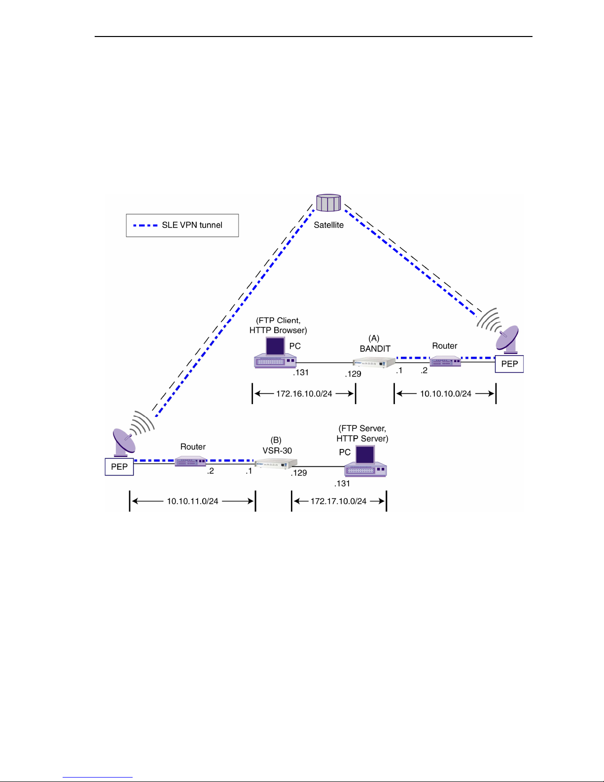
Figure 9 shows a sample satellite network combining PEP and SLE.
BANDIT Products
Figure 9. Sample Satellite Network Configuration Using Encore Networks’ SLE VPN
F.4.3.1 SLE Configuration
The BANDIT products can use the following types of VPN software:
• The BANDIT’s regular IPsec VPN software does not have SLE; all VPN tunnels in this
software are IPsec without SLE. (This is the software the BANDIT IP uses.)
• The BANDIT’s IPsec VPN software with SLE has everything; tunnels can use regular
VPN or VPN with SLE. (This is the software the VSR products use. This software is also
available in the BANDIT or the BANDIT Plus.)
The software for SLE differs slightly from the standard BANDIT software. However, the
menus do not differ, and configuration remains the same for most parameters in the
BANDIT.
Page 24

24 BANDIT™, BANDIT IP™, and BANDIT Plus™ Installation Guide
Note: The VSR products (the VSR-30 and the VSR-1200) are designed to support satellite
networks as well as ground-based networks. Any BANDIT VPN device can support both
VPN with SLE (for use over satellite networks) and VPN without SLE (for ground-based
networks), depending on the software installed in the device. Most VPN devices can also
support legacy applications.
In the BANDIT’s IPsec VPN software with SLE, all VPN tunnels use SLE, except in the
following instance:
• In SLE software, in the IP Policy Table, if you select a record, the record’s detail screen
appears. Look at the name for the Description. If the description name begins with the
letter “I” (upper case) or “i” (lower case), the configuration is IPsec VPN without SLE.
(See Figure 14.) If the Description name begins with any other initial character, the
configuration is IPsec VPN with SLE. (See Figure 11.)
You configure both types of IPsec the same way, except for this parameter. All other items needed
are configured automatically. (However, you need to supply the appropriate IP addresses.)
Note: In BANDIT software release 5.0 and above, the user does not configure FTP/HTTP
ports 20, 21, and 80 for SLE. In addition, Network Address Translation is no longer required
for SLE.
The user can modify the VPN configuration, if desired. We recommend consulting with
your Encore Networks sales representative before modifying an automatically generated
configuration.
Figure 10 shows part of the IP Policy Table for the BANDIT (A) in Figure 9. Note that
record 3 is a catch-all policy for VPN with SLE; because it is a catch-all, it must follow all
other records for VPN with SLE. Note that record 4 is a catch-all for VPN without SLE (and
must follow all other records for VPN without SLE).
Figure 11 through Figure 14 show details of the records.
Source Src Destination Dest Protocol
# Address Port Address Port /Flag Path Name I/O Action
--- --------------- ------ --------------- ------ -------- ----------- --- ------
1 172.16.10.131 * 10.10.11.1 * * * *
172.16.10.131 * 10.10.11.1 *
H-3 Action: Allow
2 172.16.10.128 * 10.10.11.1 * * * *
172.16.10.255 * 10.10.11.1 *
Tunnel To Remote 1 Action: Initiate VPN Profile: REMOTE
3 * * * * * * *
* * * *
H-1 Action: Allow
4 * * * * * * *
* * * *
I-Allow ALL Action: Allow
Figure 10. Sample Entries in IP Policy Table for BANDIT in Figure 9,
Including SLE over Satellite Networks
Page 25

BANDIT™, BANDIT IP™, and BANDIT Plus™ Installation Guide 25
1) Source Address Low : 172.16.10.131
Source Address High : 172.16.10.131
Source TCP/UDP Port Low : *
Source TCP/UDP Port High : *
Destination Address Low : 10.10.11.1
Destination Address High : 10.10.11.1
Destination TCP/UDP Port Low : *
Destination TCP/UDP Port High : *
Protocol/Flags : *
Path Name : *
Incoming/Outgoing : *
Filtering Action : Allow
VPN Profile name : N/A
Description : H-3
Figure 11. Detail of Record 1 in IP Policy Table,
for SLE over Satellite Networks
2) Source Address Low : 172.16.10.128
Source Address High : 172.16.10.255
So Address Low : 10.10.11.1
Destination Address High : 10.10.11.1
Destination TCP/UDP Port Low : *
Destination TCP/UDP Port High : *
Protocol/Flags : *
Path Name : *
Incoming/Outgoing : *
Filtering Action : Initiate
VPN Profile name : REMOTE
Description : Tunnel To Remote 1
Figure 12. Detail of Record 2 in IP Policy Table,
for SLE over Satellite Networks
3) Source Address Low : *
Source Address High : *
Source TCP/UDP Port Low : *
Source TCP/UDP Port High : *
Destination Address Low : *
Destination Address High : *
Destination TCP/UDP Port Low : *
Destination TCP/UDP Port High : *
Protocol/Flags : *
Path Name : *
Incoming/Outgoing : *
Filtering Action : Allow
VPN Profile name : N/A
Description : H-1
Figure 13. Detail of Record 3 in IP Policy Table,
for SLE over Satellite Networks
Page 26

26 BANDIT™, BANDIT IP™, and BANDIT Plus™ Installation Guide
4) Source Address Low : *
Source Address High : *
Source TCP/UDP Port Low : *
Source TCP/UDP Port High : *
Destination Address Low : *
Destination Address High : *
Destination TCP/UDP Port Low : *
Destination TCP/UDP Port High : *
Protocol/Flags : *
Path Name : *
Incoming/Outgoing : *
Filtering Action : Allow
VPN Profile name : N/A
Description : I-Allow ALL
Figure 14. Detail of Record 4 in IP Policy Table,
for IPsec VPN Traffic without SLE
Note: For VPN with SLE over satellites, there must be another BANDIT product using VPN
with SLE on the other side of the network, handling SLE for the remote side of the
connection.
Over ground-based networks, the BANDIT VPN products use non-SLE software and can
interoperate with non-BANDIT IPsec VPN gateways. For details of IPsec interoperability,
see the BANDIT Products Software Configuration and Maintenance Guide.
F.5 IP Configuration
This section discusses additional IP components you must configure in order to use the
BANDIT as a network gateway or as a VPN gateway.
1 On the Advanced Configurations menu, select Routing.
2 On the Routing menu, select IP Routing.
❖ The IP Routing Configuration menu appears.
3 See the following:
• Section F.5.1, IP Routing
• Section F.5.2, IP Quality of Service
• Section F.5.3, Network Address Translation
• Section F.5.4, Firewall
F.5.1 IP Routing
To use the VPN feature to its capacity, you must configure the device’s IP routing. Do the
following:
1 On the IP Routing Configuration menu, select the IP Routing Method you wish to use
(RIP or Static).
Page 27

BANDIT™, BANDIT IP™, and BANDIT Plus™ Installation Guide 27
2 On the IP Routing Configuration menu, do the following:
a If the IP routing method is RIP, select and configure RIP Routing. Follow the procedure
for RIP routing in the BANDIT Products Software Configuration and Maintenance Guide.
Entry IP Address Net Mask Gpt Name Next Router Mode MTU
---- --------------- -------------- ------------ -------------- ------ --- 1 192.168.169.1 255.255.255.0 MODEM 0.0.0.0 Off 1500
Add, Modify, or Delete an Entry? (Enter A, M, or D):
b If the IP routing method is Static, select and configure Static Routing. Follow the
procedure for static routing in the BANDIT Products Software Configuration and
Maintenance Guide.
Entry IP Address Net Mask Next Router Path Name Hops
1 1.2.3.4 255.0.0.0 Unnumbered a 1
Add, Modify, or Delete an Entry? (Enter A, M, or D):
For more information, see the BANDIT Products Software Configuration and Maintenance Guide.
F.5.2 IP Quality of Service
To use the VPN feature to its capacity, you must configure the device’s IP Quality of Service.
Do the following:
1 On the IP Routing Configuration menu, select IP Quality of Service.
2 On the IP Priority menu, select Prioritization.
3 On the IP Quality of Service menu, do the following:
a Select Status, and Enable IP quality of service.
b Select Quality of Service Table, and configure entries in the table.
Source Src Destination Dest
# Address Port Address Port Protocol Path Name Priority
--- --------------- ------ --------------- ------ -------- ---------- ----------
1 * * * * * * Immediate
* * * *
* * * *
Add, Modify, Insert or Delete an Entry? - (A/M/I/D) :
c Set a Default Priority for IP packets that do not match any entry in the table.
Page 28

28 BANDIT™, BANDIT IP™, and BANDIT Plus™ Installation Guide
For more information, see the BANDIT Products Software Configuration and Maintenance Guide.
F.5.3 Network Address Translation
You can use the BANDIT products for network address translation (NAT).
If your connections will include VPNs across satellite networks, the BANDIT device will use
selective layer encryption. Before configuring the NAT Table, read Section F.4.3, Selective
Layer Encryption in VPNs.
To use network address translation, do the following:
1 On the IP Routing Configuration menu, select Network Address Translation.
2 On the Network Address Translation menu, do the following:
a Select a NAT configuration scheme.
b Enable and configure the NAT configuration scheme according to your network plan—
e.g., for masquerading, or for a NAT table.
For more information, see the BANDIT Products Software Configuration and Maintenance Guide.
F.5.4 Firewall
The default settings for the BANDIT do not use the firewall feature. If you wish to configure
the firewall, do the following.
1 On the Main Menu, select Typical Configurations.
2 On the Typical Configurations menu, select Configure Firewall.
3 On the Configure Firewall menu, configure the policy table, NAT profiles, and IP
interfaces for your network’s dynamic firewall.
For more information, see the BANDIT Products Software Configuration and Maintenance Guide.
F.6 Simple Network Management Protocol
If you wish to use Simple Network Management Protocol (SNMP) with the BANDIT, do the
following to configure the device’s built-in SNMP agent:
1 On the Main Menu, select System Administration.
2 When the system asks for your password, enter the default password and press Enter.
Note: If your product order requested a different, specific password, contact your
system administrator for the password.
3 On the System Administration menu, select SNMP Configuration.
4 On the SNMP Configuration menu, do the following:
a Configure the SNMP Get Community String.
b Configure the SNMP Set Community String.
c Configure the SNMP Trap Default Address.
Page 29

BANDIT™, BANDIT IP™, and BANDIT Plus™ Installation Guide 29
d Configure IP addresses for the SNMP Trap Table.
5 Now you can configure an SNMP manager on your control terminal. (Encore Networks
does not furnish SNMP manager software.)
G Saving (Writing) the Device’s Configuration
Note: If you do not save the configuration before you reset or exit the BANDIT (or before
the connection times out), the configuration will be lost.
After the unit has been configured, save (write) the configuration. Do the following:
1 On the Main Menu, select Write Configuration.
2 Select Yes.
❖ The device will notify you when it has saved the configuration.
Note: If the device’s software detects an error in the configuration, it will not save it.
Review the configuration. After you have revised the configuration to your
satisfaction, save it.
3 Press Enter.
H Restarting (Resetting) the Device
To use the saved configuration, you must reset the BANDIT. Do the following:
Note: If you want to use your new configuration, you must save (write) the configuration
before resetting the unit. Otherwise, the new configuration will be lost.
1 On the Main Menu, select Reset Unit.
2 Select Yes.
Note: If you have not yet saved the new configuration, the system asks whether to
save it. Answer yes or no.
❖ The device resets.
3 Regardless of screen instructions, do not type anything until you see the banner:
BANDIT, ENCORE NETWORKS INC. Then press Enter.
❖ The Main Menu is displayed.
Page 30

30 BANDIT™, BANDIT IP™, and BANDIT Plus™ Installation Guide
I Exiting a Session
After the software has been configured, save (write) the configuration. Then exit the session
before disconnecting the PC, so that communication is not disrupted.
Caution: Before you exit, make sure you save (write) the configuration. Otherwise, the
!
changes you configured will be lost. See Section G, Saving (Writing) the Device’s
Configuration.
To exit the session, do the following:
1 On the Main Menu, select Exit Session.
❖ The following prompt is displayed.
Are You Sure? :
2 Select Yes.
Note: If the configuration has not been saved, the device asks you whether it should
save the new configuration. Answer Yes (or No, if you prefer not to save the
configuration).
❖ The system notifies you that it is ending the session.
Ending Session...
Note: To reconnect to the device and start a new session, press Enter.
❖ The terminal’s connection to the BANDIT starts up, and the BANDIT’s Main Menu is
displayed.
 Loading...