

Page 1
/
SERVICE MANUAL
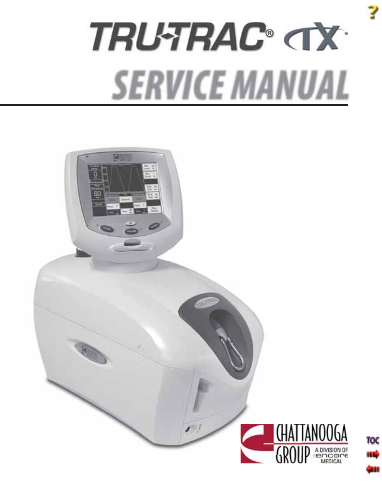
Tru-Trac® Traction Unit- Model 4779
TX® Traction Unit- Model 4759
Applies to Serial numbers 1000 and above
© 2006 Encore Medical, L.P.
ISO 13485 Certifi ed
Page 2
TABLE OF CONTENTS
Tru-Trac and TX® Therapeutic Traction Unit
FOREWORD.. .. .. .. .. .. .. .. .. .. .. .. .. .. .. .. .. .. .. .. .. .. 1
1 THEORY OF OPERATION.. .. .. .. .. .. .. .. .. .. .. .. .. 2
1.1 OVERVIEW . .. .. .. .. .. .. .. .. .. .. .. .. .. .. .. .. .. .. ..2
2 SAFETY PRECAUTIONS . .. .. .. .. .. .. .. .. .. .. .. .. 35
2.1 PRECAUTIONARY DEFINITIONS .. .. .. .. .. .. 3
2.2 PRECAUTIONARY INSTRUCTIONS .. .. .. .35
3 NOMENCLATURE .. .. .. .. .. .. .. .. .. .. .. .. .. .. .. .. .. 6
3.1 TRUTRAC AND TX UNIT
EXTERNAL COMPONENTS .. .. .. .. .. .. .. .. .. ..6
3.2 INTERNAL COMPONENTS .. .. .. .. .. .. .. .. .. ..7
4 SPECIFICATIONS .. .. .. .. .. .. .. .. .. .. .. .. .. .. .. .. .. 8
4.1 PHYSICAL SPECIFICATIONS .. .. .. .. .. .. .. .. ..8
5 TROUBLESHOOTING.. .. .. .. .. .. .. .. .. .. .. .. .. 926
5.1 TRUTRAC AND TX
ERROR MESSAGES .. .. .. .. .. .. .. .. .. .. .. ..9-13
5.2 TRUTRAC AND TX TRACTION UNIT
TESTING .. .. .. .. .. .. .. .. .. .. .. .. .. .. .. .. .. .. .. 14
5.3 VISUAL INSPECTION . .. .. .. .. .. .. .. .. .. .. .. 15
5.4 GROUND RESISTANCE TEST .. .. .. .. .. .. .. 15
5.5 LEAKAGE TESTS .. .. .. .. .. .. .. .. .. .. .. .. .. .. 15
5.6 ON/OFF SWITCH TEST . .. .. .. .. .. .. .. .. .. .. 16
5.7 ON/OFF SWITCH TROUBLESHOOTING . 16
5.8 PATIENT INTERRUPT SWITCH TEST . .. .. 17
5.9 CORD RELEASE AND RETRACT TEST.. .. 18
5.10 CORD RELEASE
TROUBLESHOOTING . .. .. .. .. .. .. .. .. .. 19-20
5.11 LOAD CELL TEST .. .. .. .. .. .. .. .. .. .. .. .. .. .. 21
5.12 LOAD CELL TROUBLESHOOTING .. .. 22-23
5.13 TOUCH SCREEN TEST .. .. .. .. .. .. .. .. .. .. .. 24
5.14 TOUCH SCREEN TROUBLESHOOTING .. 25
5.15 POWER SUPPLY TROUBLESHOOTING .. 26
6 REMOVAL & REPLACEMENT . .. .. .. .. .. .. .. .2751
6.1 SIDE COVER
REMOVAL & REPLACEMENT .. .. .. .. .. .. .. .. 27
6.2 TOP AND CORD GUIDE COVER
REMOVAL & REPLACEMENT .. .. .. .. .. .. .. .. 28
6.3 REAR COVER
REMOVAL & REPLACEMENT .. .. .. .. .. .. .. .. 29
6.4 FRONT COVER
REMOVAL & REPLACEMENT .. .. .. .. .. .. 30-31
6.5 MOTOR CONTROL BOARD
REMOVAL & REPLACEMENT .. .. .. .. .. .. .. .. 32
6.6 TOUCH SCREEEN ASSEMBLY
REMOVAL & REPLACEMENT .. .. .. .. .. 33-34
6.7 LOAD CELL ASSEMBLY
REMOVAL & REPLACEMENT .. .. .. .. .. 35-36
6.8 CLAMP SPRING ASSEMBLY
REMOVAL & REPLACEMENT .. .. .. .. .. .. .. 37
6.9 TRACTION CORD
REMOVAL & REPLACEMENT .. .. .. .. .. 38-43
6.10 CORD TENSION SPRING
REMOVAL & REPLACEMENT .. .. .. .. .. 44-45
6.11 SOLENOID ASSEMBLY
REMOVAL & REPLACEMENT .. .. .. .. .. .. .. 46
6.12 POWER SUPPLY
REMOVAL & REPLACEMENT .. .. .. .. .. 47-48
6.13 MOTOR ASSEMBLY
REMOVAL & REPLACEMENT .. .. .. .. .. 49-50
6.14 MOTOR DRIVE GEAR
REMOVAL & REPLACEMENT .. .. .. .. .. .. .. 51
7 CALIBRATION .. .. .. .. .. .. .. .. .. .. .. .. .. .. .. .. .5256
7.1 UNIT CALIBRATION .. .. .. .. .. .. .. .. .. .. .. 52-54
7.2 TOUCH SCREEN CALIBRATION .. .. .. .. .. .. 55
7.3 UNIT BURN IN . .. .. .. .. .. .. .. .. .. .. .. .. .. .. .. .. 56
8 PARTS.. .. .. .. .. .. .. .. .. .. .. .. .. .. .. .. .. .. .. .. .. .5764
8.1 TOP COVER ASSEMBLY .. .. .. .. .. .. .. .. .. .. .. 57
8.2 SIDE COVERS .. .. .. .. .. .. .. .. .. .. .. .. .. .. .. .. .. 58
8.3 FRONT AND REAR COVERS . .. .. .. .. .. .. .. .. 59
8.4 BASE AND EXTRUSION ASSEMBLY . .. .. .. 60
8.5 CHASSIS ASSEMBLY . .. .. .. .. .. .. .. .. .. .. .. .. 61
8.6 TRACTION CORD SPRING ASSEMBLY
AND POWER SUPPLY .. .. .. .. .. .. .. .. .. .. .. .. 62
8.7 SOLENOID AND CLAMP ASSEMBLIES.. .. 63
8.8 LARGE DRIVEN GEAR AND
SPOOL ASSEMBLY.. .. .. .. .. .. .. .. .. .. .. .. .. .. 64
9 SCHEMATICS . .. .. .. .. .. .. .. .. .. .. .. .. .. .. .. .. .6573
9.1 TRUTRAC AND TX TRACTION UNIT
SCHEMATICS .. .. .. .. .. .. .. .. .. .. .. .. .. .. .. 65-73
CONTROL BOARD . .. .. .. .. .. .. .. .. .. .. .. .. 66-68
MOTOR CONTROL BOARD . .. .. .. .. .. .. .. 69-70
PATIENT INTERRUPT SWITCH.. .. .. .. .. .. .. .. 71
SERIAL INTERFACE .. .. .. .. .. .. .. .. .. .. .. .. .. .. 72
SMART CARD .. .. .. .. .. .. .. .. .. .. .. .. .. .. .. .. .. 73
BLOCK DIAGRAM .. .. .. .. .. .. .. .. .. .. .. .. .. .. .. 74
10- SPECIAL FIXTURES . .. .. .. .. .. .. .. .. .. .. .. .. .. 75-78
CALIBRATION FIXTURE .. .. .. .. .. .. .. .. .. .. .. 75-78
11 WARRANTY . .. .. .. .. .. .. .. .. .. .. .. .. .. .. .. .. .. .. .79
Page 3
FOREWORD
Tru-Trac and TX® Therapeutic Traction Unit
Read, understand, and follow the Safety Precautions and all other information contained in this
manual.
This manual contains the necessary safety and field service information for those field service
technicians, certified by Chattanooga Group, to perform field service on the Tru-Trac and TX unit.
At the time of publication, the information contained herein was current and up-to-date. However,
due to continual technological improvements and increased clinical knowledge in the field of
traction therapy, as well as Chattanooga Group’s policy of continual improvement, Chattanooga
Group reserves the right to make periodic changes and improvements to their equipment and
documentation without any obligation on the part of Chattanooga Group.
It is the sole responsibility for certified field technicians to stay informed and trained in the latest
technology utilized in the Tru-Trac and TX units by Chattanooga Group. From time to time, as
significant improvements are incorporated, service bulletins will be produced and made available
on our web site (chattgroup.com) in lieu of reprinting a complete manual prematurely. These service
bulletins will provide updated service information and technological improvements to the Tru-Trac
and TX unit for use by certified service technicians.
Due to the complex nature of the technology utilized by Chattanooga Group, the recommended
troubleshooting techniques are to determine “Bad Board” and board replacement only. No board
component level troubleshooting is recommended, nor will information or parts be supplied by
Chattanooga Group.
Any board component level troubleshooting performed will be at the sole risk and liability of the
certified field service technician performing such troubleshooting techniques. Performance of such
techniques may render the warranty null and void.
Tru-Trac and TX® are prescription devices to be used only under the supervision of and by the order of a
physician or other licensed health care provider.
©2006 Encore Medical Corporation or its affiliates, Austin, Texas, USA. Any use of editorial, pictorial, or layout composition of this publication without express written consent
from the Chattanooga Group of Encore Medical, L.P. is strictly prohibited. This publication was written, illustrated, and prepared for print by the Chattanooga Group of
Encore Medical, L.P.
1
Page 4

1 THEORY OF OPERATION
1.1 OVERVIEW
The Tru-Trac and TX traction unit is comprised of several pieces of proprietary hardware and software causing
the unit to function as required allowing administration of traction therapy under the prescription and
supervision of a licensed medical practitioner.
The Touch Screen Assembly houses the necessary hardware and software to communicate to the Motor
Control Board. Communicates commands and limits as established by the user through use of the Touch
Screen. The Touch Screen Assembly, in conjunction with the Motor Control Board, monitors the functionality
of the entire system during the course of the traction therapy being administered. Should the unit
malfunction or a communication error occur, the unit will stop treatment and generate an error message to
notify the operator of a possible problem.
The Touch Screen Assembly communicates to the Motor Control Board Assembly via a proprietary bus.
The Motor Control Board communicates to the Touch Screen Assembly throughout the therapy session all
parameters via feedback from the Motor Assembly and the Load Cell Assembly.
The Touch Screen Assembly incorporates a Patient Data Card Reader/Writer for the purpose of storing Patient
Treatment Data that can then be downloaded to a PC equipped with the optional PDMS System.
Tru-Trac and TX® Therapeutic Traction Unit
2
Page 5
2 SAFETY PRECAUTIONS
Tru-Trac and TX® Therapeutic Traction Unit
2.1 PRECAUTIONARY DEFINITIONS
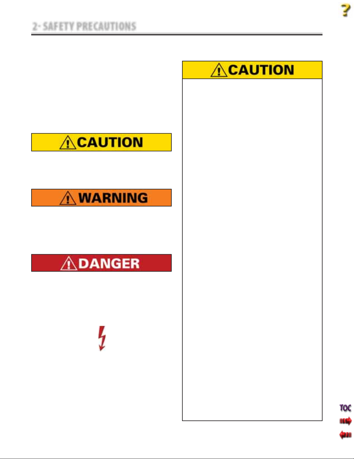
The precautionary instructions found in this
section and throughout this manual are indicated
by specific symbols. Understand these symbols
and their definitions before operating this
equipment. The definition of these symbols are as
follows:
A. Caution
Text with a “CAUTION” indicator will explain
possible safety infractions that could have the
potential to cause minor to moderate injury or
damage to equipment.
B. Warning
Text with a “WARNING” indicator will explain
possible safety infractions that will potentially
cause serious injury and equipment damage.
C. Danger
Text with a “DANGER” indicator will explain
possible safety infractions that are imminently
hazardous situations that would result in death
or serious injury.
D. Dangerous Voltage
Text with a “Dangerous Voltage” indicator serves
to inform the technician of possible hazards
resulting in the electrical charge disbursement
from certain components if handled or serviced
improperly.
E. NOTE
Throughout this manual, “NOTE” may be found.
These Notes are helpful information to aid in
the particular area or function being described.
2.2 PRECAUTIONARY INSTRUCTIONS
A. Cautions
•
Read, understand, and practice all precautionary
instructions found in this manual. Know the
limitations and hazards associated with using
any electrical traction device. Observe the
precautionary and operational decals placed on
the unit.
•
Do not use accessories other than those supplied
with the unit or recommended by Chattanooga
Group. The safety of other products has not been
established, and their use could result in injury to
the patient.
•
This unit should be transported and stored in
temperatures between 0°F and 140°F (-18°C
and 60°C) to prevent damage to the unit or its
components.
•
DO NOT operate this unit in an environment
where other devices are being used that
intentionally radiates electromagnetic energy in
an unshielded manner. Portable and mobile RF
communications equipment can affect Medical
Electrical Equipment.
•
This unit generates, uses, and can radiate radio
frequency energy and, if not installed and
used in accordance with the instructions, may
cause harmful interference to other devices
in the vicinity. However, there is no guarantee
that interference will not occur in a particular
installation. Harmful interference to other
devices can be determined by turning this (table,
unit, device, etc.) on and off. Try to correct the
interference using one or more of the following:
reorient or relocate the receiving device, increase
the separation between the equipment, connect
the equipment to an outlet on a different
circuit from that which the other device(s) are
connected and consult the Chattanooga Group
Service Department for help.
The unit should be routinely checked before each
•
use to determine all controls function normally.
Handle the unit with care. Inappropriate handling
•
of the unit may adversely affect its characteristics.
Before each use, inspect the Traction Cord for
•
wear. Prolonged wear on the cord will cause it to
break, which may cause sudden release of traction
pressure on a patient.
Test the Patient Interrupt Switch before each use
•
for power operation.
3
Page 6
2 SAFETY PRECAUTIONS
2.2 PRECAUTIONARY INSTRUCTIONS (continued)
•
Do not remove the cover. This may cause unit
damage, malfunction, electrical shock, fire, or
personal injury. There are no user-serviceable parts
inside the unit. If a malfunction occurs, discontinue
use immediately, disconnect the Mains Power Cord
from the outlet, and consult the dealer for repair
service.
•
Do not use sharp objects such as a pencil point or
ballpoint pen to operate the buttons on the LCD
base as damage may result.
•
Do not permit any foreign materials or liquids
to enter the unit. Take care to prevent any
foreign materials including, but not limited to,
inflammables, water, and metallic objects from
entering the unit. These may cause unit damage,
malfunction, electrical shock, fire, or personal
injury.
•
Do not disassemble, modify, or remodel the
unit or accessories. This may cause unit damage,
malfunction, electrical shock, fire, or personal
injury.
•
Do not use the traction unit near devices such as
X-ray units or diathermy units. These units may
emit high frequency noise that may affect the
operation of the unit.
•
Failure to use and maintain the traction unit and
its accessories in accordance with the instructions
outlined in this manual will render the warranty
void.
•
In the event of a loss of power to the unit or
when quick release is needed, traction tension
should only be released by having the patient
move towards the traction head to release the
tension on the rope. Once the tension on the rope
has been released, loosen the patient harness
adjustment straps.
•
The tool, lubrication, and locking compound
requirements listed are critical to component
removal and replacement of the unit.
•
The hardware, bolts, nuts, and screws used to
assemble the Tru-Trac and TX are SAE and Metric.
Therefore, it will be necessary to obtain both SAE
and Metric tools for removal and replacement of
components.
•
The lubricant and locking compound listed are
crucial in the assembly of certain components to
ensure patient safety and efficient operation of the
unit.
Tru-Trac and TX® Therapeutic Traction Unit
B. Warnings
Use of controls or adjustments or performance of
•
procedures other than those specified herein may
result in a hazardous traction related injury.
Before connecting the unit to an electrical outlet,
•
make certain the unit is electrically grounded by
connecting only to a grounded electrical service
receptacle conforming to the applicable national
and local electrical codes.
Do not use a damaged Mains Power Cord. Using
•
a damaged Mains Power Cord may cause unit
damage, malfunction, electrical shock, fire, or
personal injury. If the Mains Power Cord becomes
damaged, discontinue use immediately and contact
the dealer for replacement of the Mains Power Cord.
This device should be kept out of the reach of
•
children.
Always hand tighten the Lock Knob securely to
•
avoid any slippage.
•
Care must be taken when operating this unit,
adjacent to or stacked with other equipment.
Potential electromagnetic or other interference
could occur to this or other equipment. Try to
minimize this interference by not using other
equipment in conjunction with it.
•
In the event of a loss of power to the unit, traction
tension should only be released by gradually
lengthening the patient harness adjustment straps.
•
Dispose of all products in accordance with local and
national regulations and codes.
In the event that an Error message or Warning
•
appears beginning with a 2 or 3, immediately stop
all use of the system and contact the dealer or
Chattanooga Group for service. Errors and Warnings
in these categories indicate an internal problem
with the unit that must be tested by Chattanooga
Group or a Field Service Technician certified by
Chattanooga Group before any further operation or
use of the unit. Use of a unit that indicates an Error
or Warning in these categories may pose a risk of
injury to the patient, user, or may cause extensive
internal damage to the unit.
Unit failing Dielectric Withstand and/or Leakage
•
Tests could indicate serious internal problems.
DO NOT place the back into service! Send unit to
factory for repair! DO NOT attempt to repair the unit
in the field!
Unplug the unit from the power source before
•
attempting removal or replacement procedures to
prevent electrical shock.
When performing Unit Calibration Procedure, the
•
Calibration Fixture Load Cell must be set to US lbs.
4
Page 7
2 SAFETY PRECAUTIONS
2.2 PRECAUTIONARY INSTRUCTIONS (continued)
Use only accessories that are specially designed
•
for this unit. Do not use accessories manufactured
by other companies on this (table, unit, device,
etc.). Chattanooga Group is not responsible for
any consequence resulting from using products
manufactured by other companies. The use
of other accessories or cables may result in
increased emissions or decreased immunity of
this (table, unit, device, etc.).
This component removal and replacement
•
procedure requires that the following be performed
after component or assembly replacement to
ensure proper alignment and operation of the unit:
COMPLETE CALIBRATION OF UNIT
Refer to Section 7
AND
MINIMUM OF 2 HOUR BURN IN OF UNIT AFTER
SUCCESSFUL CALIBRATION Refer to Section 7
Failure to perform either of these procedures, after
a component or assembly replacement will void
warranty and may result in injury to patients
and/or severe equipment damage.
It is not recommend tying a new knot in a cord that
•
has frayed or failed in use or is worn in an area from
constant use. The cord must be replaced.
C. Dangers
DO NOT connect the unit to an electrical
•
supply without first verifying that the
power supply is the correct voltage.
Incorrect voltage may cause unit damage,
malfunction, electrical shock, fire, or
personal injury. Your unit was constructed
to operate only on the electrical voltage
specified on the Voltage Rating and Serial
Number Plate. Contact the Chattanooga
Group dealer if the unit is not properly
rated.
Power Supplies retain High Voltage!
•
Discharge the C4 Capacitor prior to
•
complete removal of the Power Supply.
Discharge the C4 Capacitor prior to
•
handling of the new Power Supply.
Tru-Trac and TX® is a prescription device to
•
be used only under the supervision of and
by the order of a physician or other licensed
health care provider.
Do not use any other knot styles in the
•
Cord other than those specified in this
manual. Use of other knot styles could
cause Cord to completely disengage from
the system and may cause serious injury
to patient and personnel.
Tru-Trac and TX® Therapeutic Traction Unit
5
Page 8
3 NOMENCLATURE
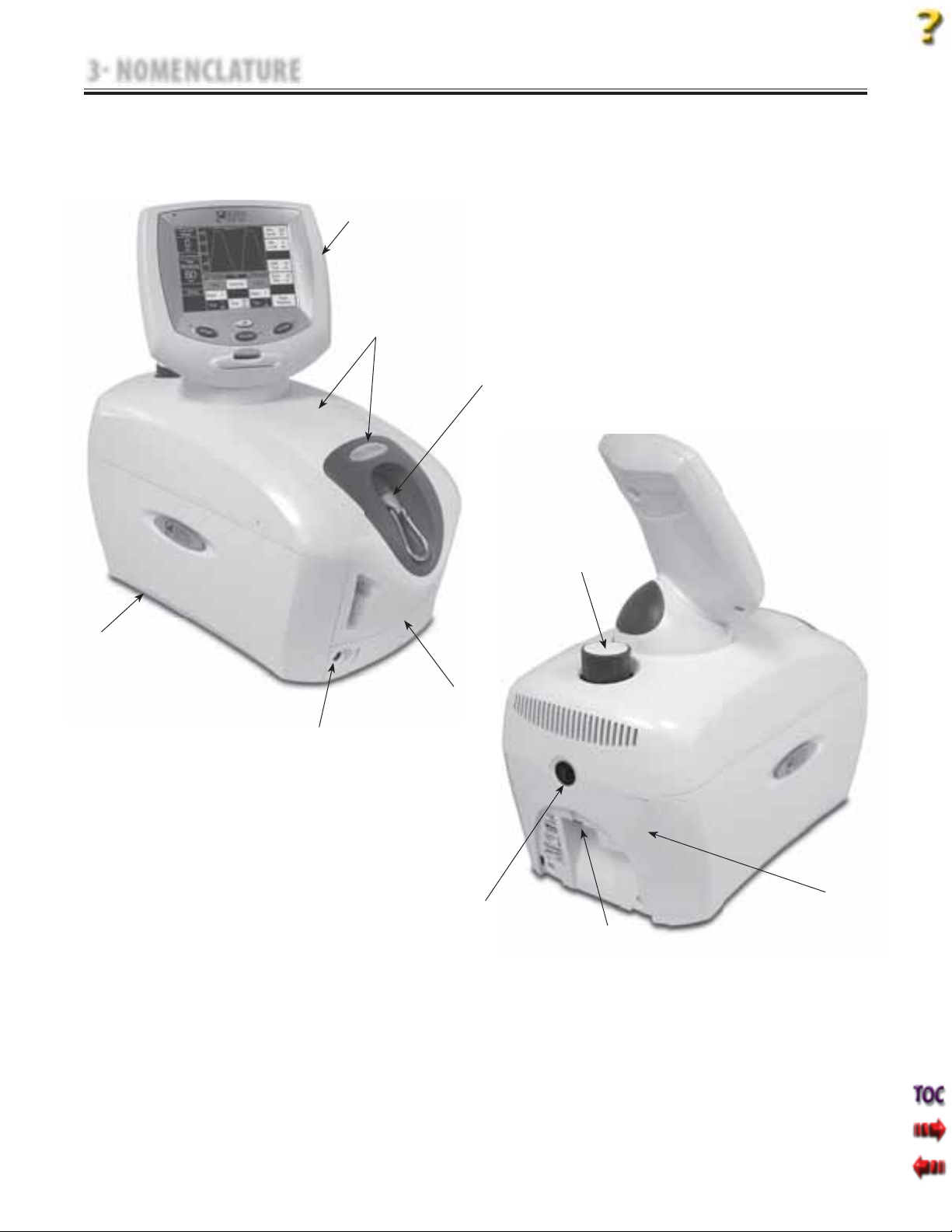
3.1 TRUTRAC AND TX UNIT EXTERNAL COMPONENTS
The nomenclature graphics below, Figure 3.1,
indicate the general locations of the major external
components of the Tru-Trac and TX traction unit.
1
2
Know the components and their functions before
performing any operation of or service to the
Tru-Trac and TX traction unit.
3
Tru-Trac and TX® Therapeutic Traction Unit
7
6
4
5
10
9
8
FIGURE 3.1
Touch Screen Assembly
1.
Top and Cord Guide Cover
2.
Traction Cord Knuckle
3.
Front Cover
4.
Patient Interrupt Switch Receptacle
5.
Side Cover
6.
Clamp Assembly Knob
7.
Rear Cover
8.
Mains Power Cord Receptacle
9.
On/Off Power Switch
10.
6
Page 9
3 NOMENCLATURE
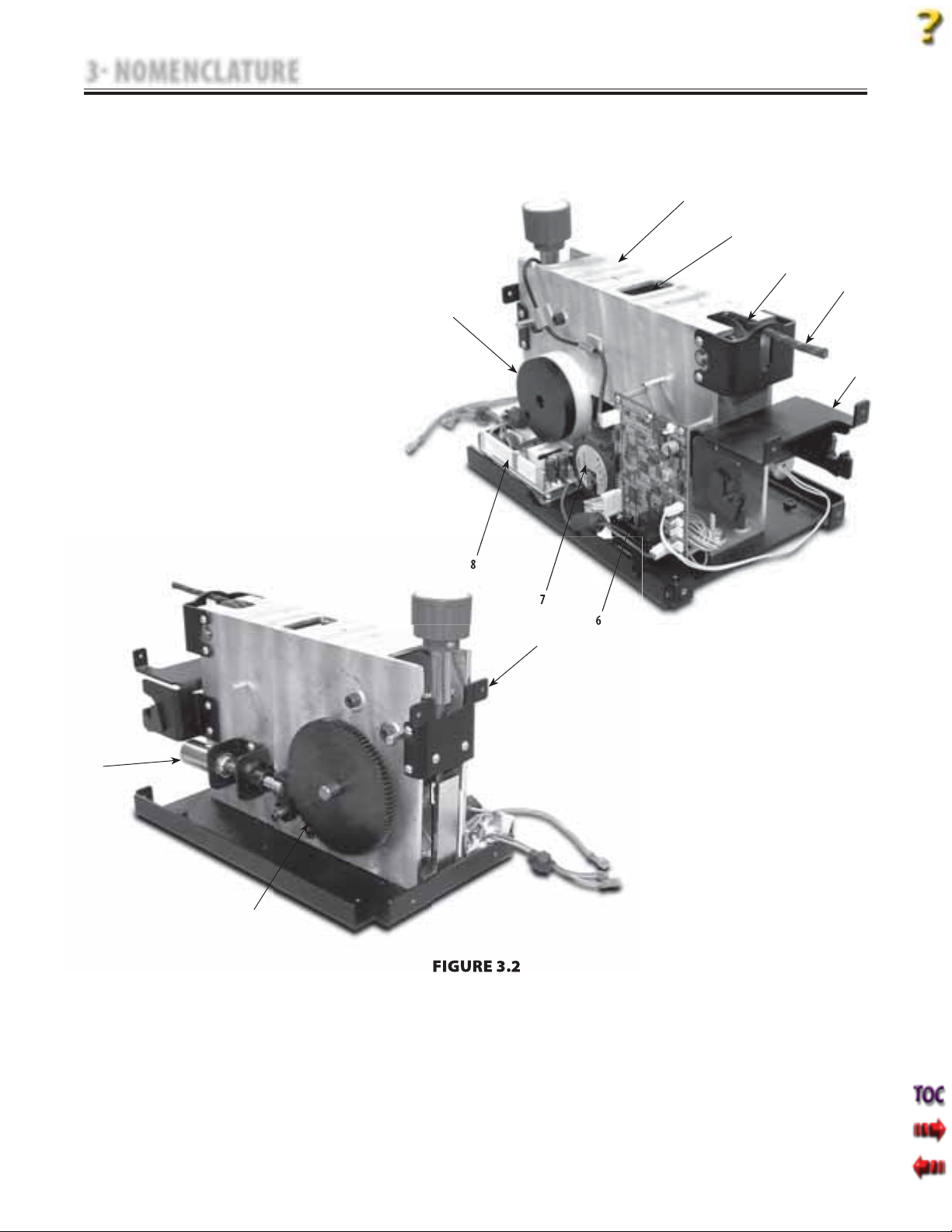
3.2 INTERNAL COMPONENTS
The nomenclature graphics below, Figure 3.2,
indicate the locations of the major internal
components of the Tru-Trac and TX traction unit.
Tru-Trac and TX® Therapeutic Traction Unit
Know the components and their functions before
performing any operation of or service to the
Tru-Trac and TX traction unit.
1
2
3
4
9
5
8
7
6
10
12
11
FIGURE 3.2
Chassis
1.
Load Cell
2.
Top Front Traction Cord Guide
3.
Traction Cord
4.
Front Cover Mounting Bracket
5.
Motor Control Board
6.
Motor Assembly
7.
Power Supply
8.
Cord Tension Spring and Housing
9.
Clamp Spring Assembly
10.
Large Driven Gear
11.
Solenoid Assembly
12.
7
Page 10
4 SPECIFICATIONS
PARAMETERS
MINIMUM
MAXIMUM
INCREMENTS
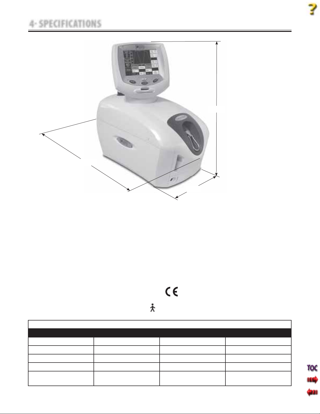
4.1 PHYSICAL SPECIFICATIONS
DEPTH
Tru-Trac and TX® Therapeutic Traction Unit
HEIGHT
WIDTH
FIGURE 4.1
Width . . . . . . . . . . . . . . . . . . . . . . . . . . . . . . . . . 24 cm (9.5 in)
Depth . . . . . . . . . . . . . . . . . . . . . . . . . . . . . . . 45 cm (17.5 in)
Height . . . . . . . . . . . . . . . . . . . . . . . . . . . . . . . 45 cm (17.5 in)
Weight
Traction Modes. . . . . . . . . . . . . . . . . Static, Intermittent,
Cyclic, and their combinations.
Traction Type . . . . . . . . . . . . . . . . . . . . . . . . . . . Mechanical
LCD Display . . . . . . . . . . . . .High contrast monochrome
Standard Weight . . . . . . . . . . . . . . . . . . . . . . . .14 kg (30 lbs)
Shipping Weight . . . . . . . . . . . . . . . . . . . . . . . .18 kg (40 lbs)
Power
Voltage. . . . . . . . . . . . . . . . . . . . . . . . 100 V-240 V (50/60 Hz)
Power Consumption . . . . . . . . . . . . . . . . . . . . . . . . . . . 75 VA
Regulatory Compliance
Meets Directive 93 /42 /EEC
IEC/UL/EN: 60601-1 and 60601-1-2
CAN C22.2 No. 601.1-M90w/AZ
Current Consumption . . . . . . . . . . . . . . . . . . . . . . 3.2 A Max
Electrical Class . . . . . . . . . . . . . . . . . . . . . . . . . . . . . . . . .Class I
0413
Electrical Type . . . . . . . . . . . . . . . . . . . . . . . . . . . . . .Type B
TRACTION TENSION SPECIFICATIONS
PARAMETERS
MINIMUM
MAXIMUM
INCREMENTS
Traction Period 1 minute 99 minutes 1 minute
Hold Period 0 seconds 99 seconds 1 second
Rest Period 0 seconds 99 seconds 1 second
Traction Tension 0 kg (0 lb/0 N) 90 kg (200 lb/890 N) 1 kg (1 lb/5 N)
Progrssive and
1 step 9 steps 1 step
Regressive Steps
Touch Screen
8
Page 11
5 TROUBLESHOOTING
5.1 TRUTRAC AND TX ERROR MESSAGES
A. The following information is provided
as an aid in defining the Software Error
Messages of the Tru-Trac and TX traction unit.
Once a particular Error Message is defined,
the information will also list probable causes
and possible remedies. Once the problem
area is determined, subsequent tests for
verification will be necessary to determine
the subassembly or PC Board to be replaced.
Tru-Trac and TX® Therapeutic Traction Unit
In the case of PC Boards, all troubleshooting
and tests will be to validate a “Bad Board”
only. No component level troubleshooting
information is or will be provided by
Chattanooga Group for field troubleshooting
of PC board components.
B. Once a particular subassembly or PC Board
has been determined as bad, refer to the
appropriate Removal & Replacement
Section for the board affected and follow the
instructions for replacement of the board.
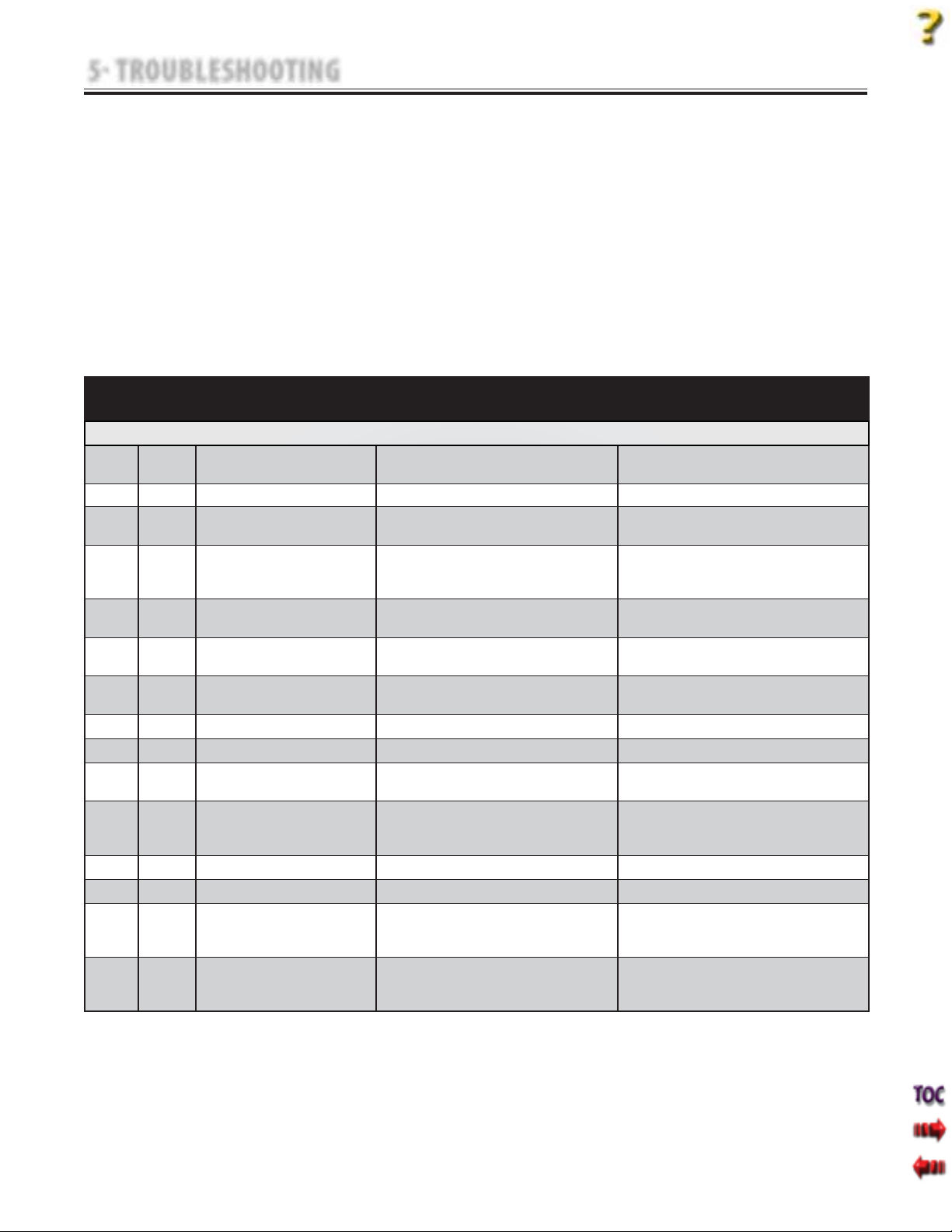
ERROR
CODE
ERROR
TYPE
DEFINITION PROBABLE CAUSES POSSIBLE REMEDY
USER CORRECTABLE WARNING MESSAGES
100 WARNING Treatment has been running for 8 seconds,
but no tension is detected on the Cord.
101 WARNING Patient pressed Patient Switch. Patient Interrupt Switch button pressed. Touch the Touch Screen to clear message.
102 WARNING Patient Switch is unplugged. Patient Interrupt Switch not properly connected to unit. Properly connect Patient Interrupt Switch and touch Touch
104 WARNING User selected Patient Card button on
utilities screen, but no traction treatments
were found on the card.
105 WARNING User selected save to card, but no card is
inserted into the unit.
106 WARNING User selected save to card, but the card
currently inserted is not a Patient Card.
107 WARNING User selected save to card, but the card
currently inserted is full.
108 WARNING User typed in a blank patient name. No Patient ID assigned. Enter Patient ID.
109 WARNING User typed in a blank protocol name. No Protocol name entered. Enter Protocol name.
110 WARNING User attempted to access a MMC function,
but no MMC is inserted into the unit.
111 WARNING User attempted to upgrade software, but
the MMC in the unit is not a software
upgrade MMC.
112 WARNING Error upgrading Control Board software. Unknown Contact Dealer or Chattanooga Group for Service.
113 WARNING Error upgrading motor board software. Unknown Contact Dealer or Chattanooga Group for Service.
114 WARNING User pressed START, but has not yet set
the Max Level value to a value greater
than zero.
115 WARNING User pressed HOME button from treatment
review screen while a treatment was
running.
Too much slack in Traction Cord Remove Traction Cord Slack.
Screen to clear message.
Wrong or bad Patient Data Card inserted into unit. Insert correct Patient Data Card.
No Patient Data Card inserted. Properly insert correct Patient Data Card into unit.
Wrong or bad Patient Data Card inserted into unit. Insert correct Patient Data Card.
Memory full on Patient Data Card used. Save Data to PDMS and erase Patient Data Card.
No Multimedia Card (MMC) inserted into unit. Insert Multimedia Card (MMC) into unit.
Wrong Multimedia Card (MMC) inserted into unit. Insert proper Mutimedia Card (MMC).
User has not completed Treatment Set Up. Complete Treatment Set Up prior to pressing START.
Home button has been pressed. Press STOP to end treatment prior to pressing HOME.
9
Page 12
5 TROUBLESHOOTING
Tru-Trac and TX® Therapeutic Traction Unit
5.1 TRUTRAC AND TX ERROR MESSAGES (continued)
In the event that an Error message or Warning appears beginning with a 2 or 3, immediately stop all use of the unit and contact the dealer or Chattanooga
Group for service. Errors and Warnings in these categories indicate an internal problem with the unit that must be tested by Chattanooga Group or a Field
Service Technician certified by Chattanooga Group before any further operation or use of the unit. Use of a unit that indicates an Error or Warning in these
categories may pose a risk of injury to the patient, user, or may cause extensive internal damage to the unit.
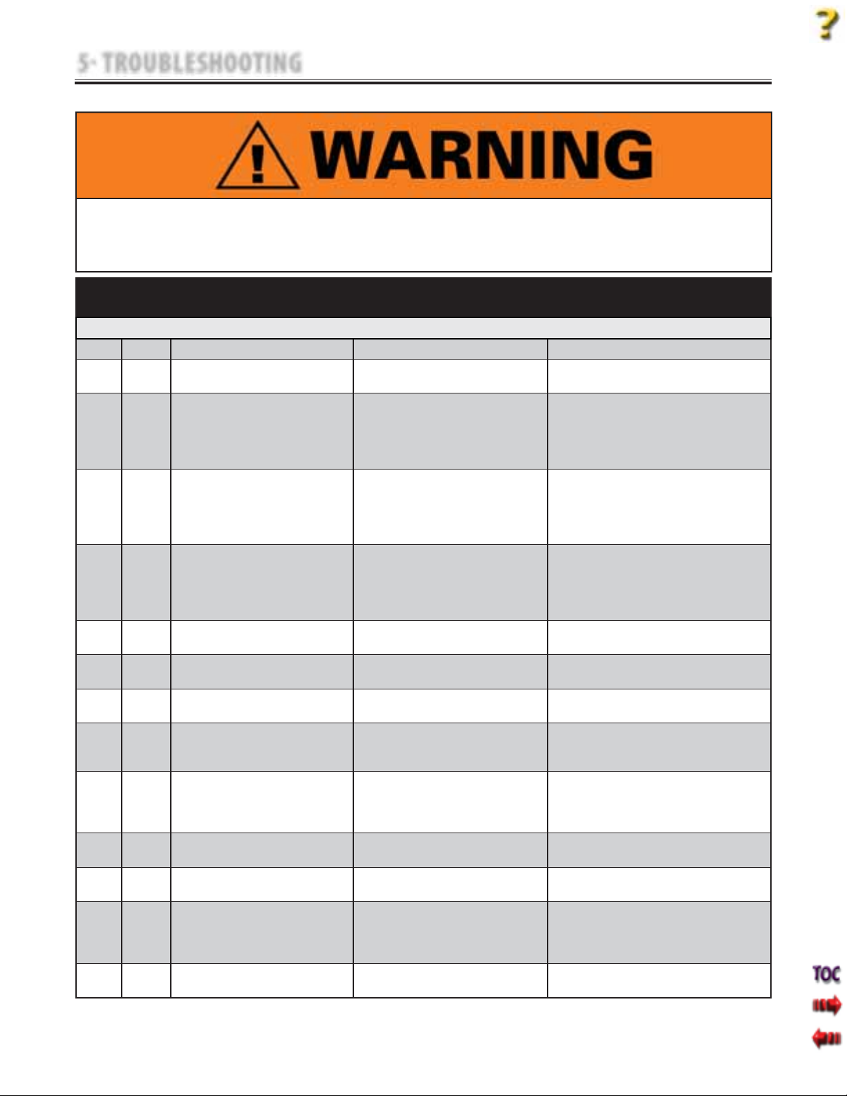
ERROR
CODE
ERROR
TYPE
DEFINITION PROBABLE CAUSES POSSIBLE REMEDY
ERROR MESSAGES (200-223) REQUIRING TECHNICAL ASSISTANCE
200 ERROR The motor PCB has reset. Motor Control Board is bad. If the Error repeats routinely, replace Motor Control Board.
201 ERROR Error communicating with the realtime clock
chip.
202 ERROR The motor PCB returned an error while
performing the zero Load Cell function.
203 ERROR Timeout waiting for the motor PCB to perform
the zero Load Cell calibration.
204 ERROR Timeout waiting for the motor PCB to perform
the motor current calibration.
205 ERROR A Motor fault error has occurred while a
treatment was running.
206 ERROR The Motor PCB cannot get to the desired tension. Internal Mechanical Jam of unit.
207 ERROR We have detected a motor current error
(MC_MON pin on motor PCB).
208 ERROR We have detected a Load Cell limit error
(LC_MON pin on motor PCB).
209 ERROR Error erasing a patient card. Bad Patient Data Card.
210 ERROR CRC not correct on treatment just read from
Patient Card.
211 ERROR Error reading default protocol on power up so
must rebuild protocols to factory presets.
212 ERROR The Motor PCB fl agged a comm watchdog error. Touch Screen Assembly did not poll Motor Control
213 ERROR Motor PCB has indicated that the zero calibration
value is invalid and needs to be calibrated.
Control Board Communication Error. If the Error repeats routinely, replace Touch Screen Assembly.
Bad Load Cell Assembly
Motor Control Board Communication Error.
Bad Load Cell
Bad Motor Control Board
Motor Control Board Communication Error. 1. Ensure there is no slack in the Cord.
Internal mechanical jam of unit.
Bad Motor Control Board or Motor Assembly.
Bad Motor Control Board or Motor Assembly.
Unit out of calibration. Perform Unit Calibration and Burn In procedures.
Unit is out of calibration.
Bad Motor Control Board.
Bad Load Cell Assembly.
Bad Touch Screen Assembly.
Bad Patient Data Card.
Bad Touch Screen Assembly.
EEPROM is corrupt. If the Error repeats routinely, replace Touch Screen Assembly.
Board in a reasonable amount of time.
Unit is out of calibration. Perform Unit Calibration and Burn In procedures.
1. Check Cables and Harnesses for proper seating and
connection on Motor Control Board.
2. Replace Load Cell Assembly.
3. Replace Motor Control Board.
4. Replace Touch Screen Assembly.
1. Ensure there is slack in the Cord.
2. Check Cables and Harnesses for proper seating and
connection on Motor Control Board.
3. Replace Load Cell.
4. Replace Motor Control Board.
2. Check Cables and Harnesses for proper seating and
connection on Motor Control Board.
3. Replace Load Cell.
4. Replace Motor Control Board.
1. Correct any internal mechanical jam.
2. Replace bad Motor Control Board or bad Motor Assembly.
1. Correct any internal mechanical jam.
2. Replace bad Motor Control Board or bad Motor Assembly.
1. Perform Unit Calibration and Burn In procedures.
2. Replace Motor Control Board.
3. Replace Load Cell Assembly.
1. Try known good Patient Data Card.
2. Check Cables and Harnesses for proper seating and
connection on Motor Control Board.
3. Replace Touch Screen Assembly.
1. Try known good Patient Data Card.
2. Replace Touch Screen Assembly.
1. Check Cables and Harnesses for proper seating and
connection on Motor Control Board.
2. If the Error repeats routinely, replace Touch Screen
Assembly.
10
Page 13
5 TROUBLESHOOTING
Tru-Trac and TX® Therapeutic Traction Unit
5.1 TRUTRAC AND TX ERROR MESSAGES (continued)
In the event that an Error message or Warning appears beginning with a 2 or 3, immediately stop all use of the unit and contact the dealer or Chattanooga
Group for service. Errors and Warnings in these categories indicate an internal problem with the unit that must be tested by Chattanooga Group or a Field
Service Technician certified by Chattanooga Group before any further operation or use of the unit. Use of a unit that indicates an Error or Warning in these
categories may pose a risk of injury to the patient, user, or may cause extensive internal damage to the unit.
ERROR
CODE
ERROR
TYPE
DEFINITION PROBABLE CAUSES POSSIBLE REMEDY
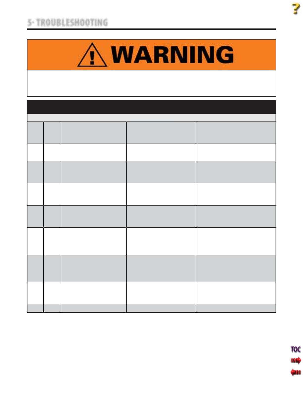
ERROR MESSAGES (200-223) REQUIRING TECHNICAL ASSISTANCE (continued)
214 ERROR User has confi gured a treatment such that it takes
too much memory to compute the treatment
steps. Unit will default back to the default power
up protocol.
215 ERROR Internal error, unit cannot get the next treatment
step information, treatment is terminated.
217 ERROR Error reading a MMC. Bad Mutimedia Card (MMC).
218 ERROR Error upgrading Control Board software. Bad Mutimedia Card (MMC).
219 ERROR Error upgrading Control Board software. Bad Mutimedia Card (MMC).
220 ERROR Error upgrading Motor Control Board software. Bad Mutimedia Card (MMC).
221 ERROR Error upgrading Motor Control Board software. Bad Mutimedia Card (MMC).
222 ERROR Patient switch is shorted. Patient Interrupt Switch not completely seated in
223 ERROR Beta version evaluation period has expired. Unit is designated BETA Test Unit. Immediately return unit to Chattanooga Group.
Under normal operating conditions, this Error should
never appear.
Multimedia Card (MMC) Data is corrupt.
Multimedia Card (MMC) interface not working.
Improper cable connection to Motor Control Board.
Bad Touch Screen Assembly.
Improper cable connection to Motor Control Board.
Bad Touch Screen Assembly.
Improper cable connection to Motor Control Board.
Bad Touch Screen Assembly.
Improper cable connection to Motor Control Board.
Bad Motor Control Board.
Bad Touch Screen Assembly.
Improper cable connection to Motor Control Board.
Bad Motor Control Board.
Bad Touch Screen Assembly.
connector.
Bad Patient Interrupt Switch.
Bad Patient Interrupt Switch Connector.
Remove unit from service and report exact treatment
parameters to Chattanooga Group.
1. Try known good Multimedia Card (MMC).
2. Remove unit from service and report exact treatment
parameters to Chattanooga Group.
1. Try known good Multimedia Card (MMC).
2. Check Cables and Harnesses for proper seating and
connection on Motor Control Board.
3. Replace Touch Screen Assembly.
1. Try known good Multimedia Card (MMC).
2. Check Cables and Harnesses for proper seating and
connection on Motor Control Board.
3. Replace Touch Screen Assembly.
1. Try known good Multimedia Card (MMC).
2. Check Cables and Harnesses for proper seating and
connection on Motor Control Board.
3. Replace Touch Screen Assembly.
1. Try known good Multimedia Card (MMC).
2. Check Cables and Harnesses for proper seating and
connection on Motor Control Board.
3. Replace Motor Control Board.
4. Replace Touch Screen Assembly.
1. Try known good Multimedia Card (MMC).
2. Check Cables and Harnesses for proper seating and
connection on Motor Control Board.
3. Replace Motor Control Board.
4. Replace Touch Screen Assembly.
1. Properly connect Pateint Interrupt Switch to unit.
2. Use a known good Pateint Interrupt Switch.
3. Replace Patient Interrupt Switch Connector on unit.
11
Page 14
5 TROUBLESHOOTING
Tru-Trac and TX® Therapeutic Traction Unit
5.1 TRUTRAC AND TX ERROR MESSAGES (continued)
In the event that an Error message or Warning appears beginning with a 2 or 3, immediately stop all use of the unit and contact the dealer or Chattanooga
Group for service. Errors and Warnings in these categories indicate an internal problem with the unit that must be tested by Chattanooga Group or a Field
Service Technician certified by Chattanooga Group before any further operation or use of the unit. Use of a unit that indicates an Error or Warning in these
categories may pose a risk of injury to the patient, user, or may cause extensive internal damage to the unit.
ERROR
ERROR
CODE
300
through
CRITICAL
307
308 CRITICAL
309 CRITICAL
310 CRITICAL
311 CRITICAL
312 CRITICAL
313 CRITICAL
314 CRITICAL
TYPE
ERROR
ERROR
ERROR
ERROR
ERROR
ERROR
ERROR
ERROR
DEFINITION PROBABLE CAUSES POSSIBLE REMEDY
CRITICAL ERRORS (300-314) DEMANDING TECHNICAL SERVICE
Communication Error between Touch Screen and Motor
Control Board.
We are supposed to be increasing tension, but tension
is not increasing.
We are supposed to be decreasing tension, but tension
is actually increasing.
We are reading > 0 tension when we should be
reading zero.
We are reading < 0 tension when we should be
reading zero.
We have detected that the motor is running too fast. Bad Motor Control Board.
Internal memory error. Bad Touch Screen. Replace Touch Screen Assembly.
Error reading EEPROM. Bad Touch Screen. Cycle power to unit. If the Error repeats, then replace
Communication Error. 1. Check Cables and Harnesses for proper seating and
Slack in Cord.
Bad Load Cell.
Bad Motor Control Board.
Unit out of calibration.
Bad Harness connection.
Bad Load Cell.
Bad Motor Control Board.
Unit out of calibration. Perform Unit Calibration and Burn In procedures.
Unit out of calibration.
Bad Load Cell.
Bad Motor Control Board.
Bad Motor Assembly.
connection on Motor Control Board.
2. Replace Motor Control Board.
3. Replace Touch Screen Assembly.
1. Remove slack in Cord.
2. Check Cables and Harnesses for proper seating and
connection on Motor Control Board.
3. Replace Load Cell.
4. Replace Motor Control Board.
1. Perform Unit Calibration and Burn In procedures.
2. Check Cables and Harnesses for proper seating and
connection on Motor Control Board.
3. Replace Load Cell.
4. Replace Motor Control Board.
1. Perform Unit Calibration and Burn In procedures.
2. Check Cables and Harnesses for proper seating and
connection on Motor Control Board.
3. Replace Load Cell.
4. Replace Motor Control Board.
1. Replace Motor Control Board.
2. Replace Motor Assembly.
Touch Screen Assembly.
12
Page 15

NOTES
Tru-Trac and TX® Therapeutic Traction Unit
13
Page 16
5 TROUBLESHOOTING
5.2 TRUTRAC AND TX TRACTION UNIT TESTING
A. General- Electronic
1. Information within this section in respect to
electronic components is intended to aid
in troubleshooting the PCB's of the Tru-Trac
and TX units to “Board Level” only.
These tests are the standard testing
procedures and methods used at the factory
before shipment of the unit.
2. Due to the complex nature of the technology
utilized by Chattanooga Group, the
recommended PCB troubleshooting
techniques are to determine “Bad Board” and
board replacement only. No PCB
component level troubleshooting is
recommended nor will information or parts
be supplied by Chattanooga Group. Any PC
board component level troubleshooting
performed will be at the sole risk and liability
of the Service Technician performing such
troubleshooting techniques.
3. Once a particular PCB has been
determined as bad, replace the PCB. Use
only Chattanooga Group replacement parts
and hardware.
B. General- Replacement Components
Critical component replacement parts for the
traction unit are available as subassemblies only.
This is due to the accuracy required and the
critical nature of the subassembly within the
unit for power function and operation. Individual
components of these subassemblies will not be
made available by Chattanooga Group.
C. General- Tests and Repair Procedures
1. Certain tests and repair procedures require
the use of special tools and/or fixtures.
These will be listed at the particular test
where they are required. Testing with any
other special tool or fixture other than those
stated could give erroneous readings or test
results. Always perform the tests exactly as
stated to ensure accurate results.
2. Test equipment settings will be listed for
each test performed prior to the respective
test to ensure the test is performed to
Chattanooga Group standards and ensure
power readings.
3. The troubleshooting and repair of the
units are to be performed only by authorized
technicians trained and certified by
Chattanooga Group.
D. Tools, Fixtures, and Equipment Required
1. Dielectric Withstand (Hi-Pot) and ground
resistance tester.
Tru-Trac and TX® Therapeutic Traction Unit
NOTE:
Adjust Dielectric Withstand tester to indicate fault with
120 kOhm load across the output when at specified
test voltage.
2. Milliohm Meter
3. Digital Multimeter
4. Required Hand Tool
•
#1 Phillips Screwdriver
•
#2 Phillips Screwdriver
•
Flat Blade Screwdriver
•
Calibrated Torque Wrench- 200 inch
pound or 2,500 Newton meter minimum
capacity.
Allen Wrenches
•
SAE- 3/32, 5/32, and 9/64 in
•
Metric- 3 mm
•
Hex Key Sockets for Torque Wrench
•
SAE- 3/32 and 5/32 in
•
Metric- 4 mm
•
Needle Nose Pliers
•
Tape Measure- 12 ft (3 meter) minimum
•
Ratchet
•
7mm Box End Wrench
•
Pick for removing connector wires.
•
5. Touch Screen to Cover Assembly Jig
6. Calibration Fixture with calibrated Strain
Meter.
7. Solenoid Assembly Mounting Jig. P/N 48139.
The tool, lubrication, and locking compound
requirements listed are critical to component
removal and replacement of the unit.
The hardware, bolts, nuts, and screws used to
assemble the Tru-Trac and TX are SAE and Metric.
Therefore, it will be necessary to obtain both SAE
and Metric tools for removal and replacement of
components.
The lubricant and locking compound listed are
crucial in the assembly of certain components to
ensure patient safety and efficient operation of the
unit.
14
Page 17
5 TROUBLESHOOTING
Tru-Trac and TX® Therapeutic Traction Unit
5.3 VISUAL INSPECTION
A. General
Visually inspect the unit. A visual
inspection can, to an experienced Technician,
indicate possible abuse of the unit and
internal problems.
5.4 GROUND RESISTANCE TEST
A. Voltage Specifications
Models 4759 and 4779 . . . . . . . . .
B. Specification
Maximum Acceptable Resistance: 100 milliohms
C. Equipment Required
Milliohm Meter
D. Tes t
Place unit on level work surface.
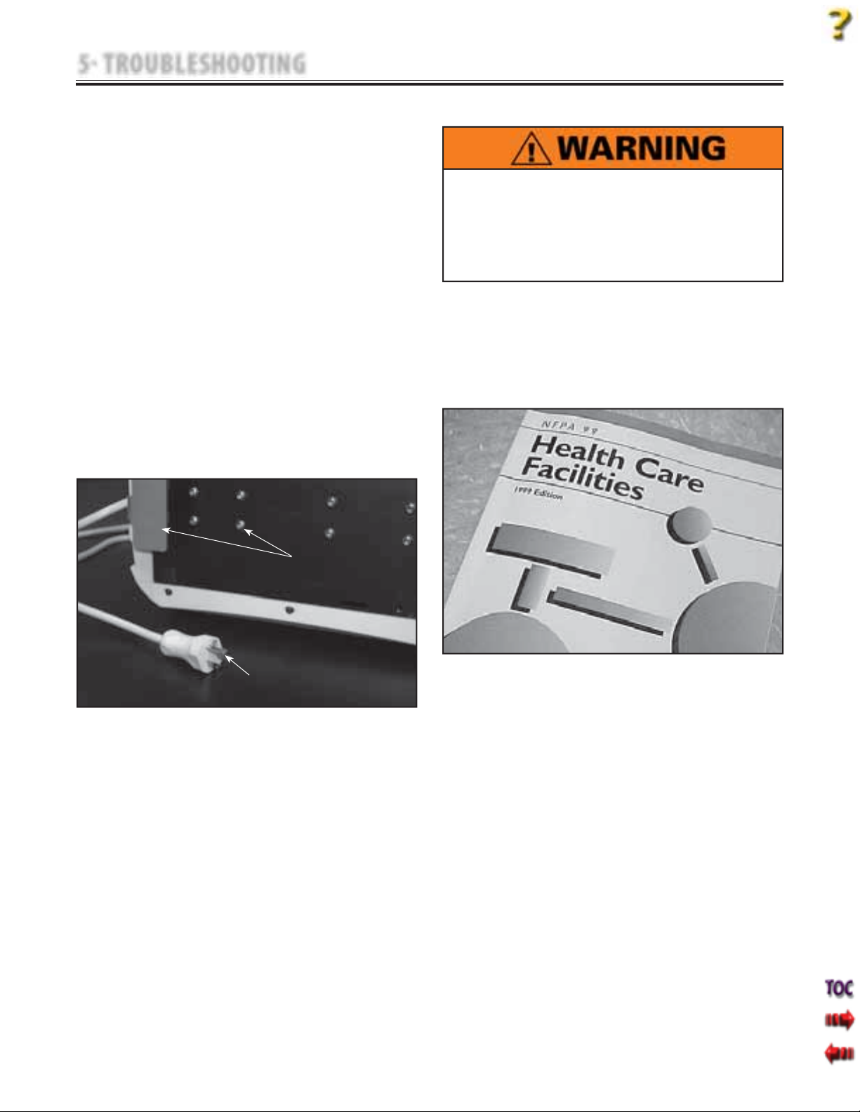
Place one meter probe on the ground prong of
power supply and the other to any exposed
metal or screw on the unit. See Figure 5.1.
Input: 100-240 VAC
50/60 Hz, 75 VA
5.5 LEAKAGE TESTS
UNIT FAILING DIELECTRIC WITHSTAND AND/OR
LEAKAGE TESTS COULD INDICATE SERIOUS
INTERNAL SYSTEM PROBLEMS.
DO NOT PLACE UNIT BACK INTO SERVICE!
SEND UNIT TO FACTORY FOR REPAIR! DO NOT
ATTEMPT TO REPAIR IN THE FIELD!
Test Voltage Spec . . . . . . . . . . . . . . . . . . . . . . . . . . . . . .
Conduct all necessary leakage tests as required per
“Chapter 7 Electrical Equipment” of the 1999, or
later, edition of the NFPA (National Fire Protection
Association) “Health Care Facilities” standards.
See Figure 5.2.
1000 V
FIGURE 5.1
NOTE:
U.S.A. Power Cord Illustrated.
Unit is illustrated on its side.
EXPOSED METAL
FIGURE 5.2
GROUND PRONG
NOTE:
The NFPA "Health Care Facilities" standards are specific
to the U.S.A. All other technicians should verify their
country's requirements for these tests.
15
Page 18
5 TROUBLESHOOTING
5.6 ON/OFF SWITCH TEST
A. Specification
Unit turns Off and On
B. Equipment Required
None
C. On/Off Switch Test Procedure
1. Place unit on level work surface.
2. Plug Power Cord into grounded power source
with appropriate voltage. See Specifications
on page 8.
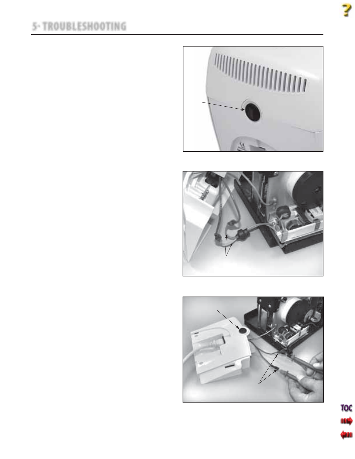
3. Turn unit Off and back On with Power Switch.
See Figure 5.3.
D. Test Result
1. If unit turns Off and On, unit passed test.
2. If unit does not turn Off and On, unit failed
test. Refer to: 5.7 On/Off Switch
Troubleshooting below.
5.7 ON/OFF SWITCH TROUBLESHOOTING
A. Specification
Appropriate AC voltage.
B. Equipment Required
Digital Multimeter
3/32 in Allen Wrench
C. On/Off Switch Troubleshooting Procedure
1. Disconnect unit from power source.Remove
Side Covers. Refer to 6.1 Side Cover Removal &
Replacement.
2. Remove Top Cover. Refer to 6.2 Top and Cord
Guide Cover Removal & Replacement.
3. Remove Rear Cover leaving harnesses
connected. Refer to 6.3 Rear Cover Removal
and Replacement.
4. Disconnect the Blue and Red wires from the
Power Supply to the Power Switch. See
Figure 5.4.
5. Set Multimeter to AC and to the appropriate
voltage setting. Connect Multimeter Leads
to the Blue and Brown wire Connectors from
the Power Switch. See Figure 5.5.
6. Plug unit into a grounded power source with
appropriate voltage. Turn Power Switch On
and take reading from Multimeter.
D. Test Result
1. If Multimeter reads appropriate voltage, unit
passed test. If unit will not power up, refer to
5.15 Power Supply Troubleshooting.
2. If Multimeter does not read appropriate
voltage.
Replace Power Switch.
Tru-Trac and TX® Therapeutic Traction Unit
ON/OFF
SWITCH
FIGURE 5.3
DISCONNECT RED AND BLUE
POWER SUPPLY WIRES
FIGURE 5.4
ON/OFF
SWITCH
MULTIMETER
CONNECTED TO BLUE
AND BROWN WIRES
FIGURE 5.5
16
Page 19
5 TROUBLESHOOTING
5.8 PATIENT INTERRUPT SWITCH TEST
A. Specification
Unit displays Error 101 or 102 at the
respective test.
B. Equipment Required
None
C. Patient Interrupt Switch Test Procedure
1. Place unit on level work surface. Plug Power
Cord into grounded power source with
appropriate voltage.
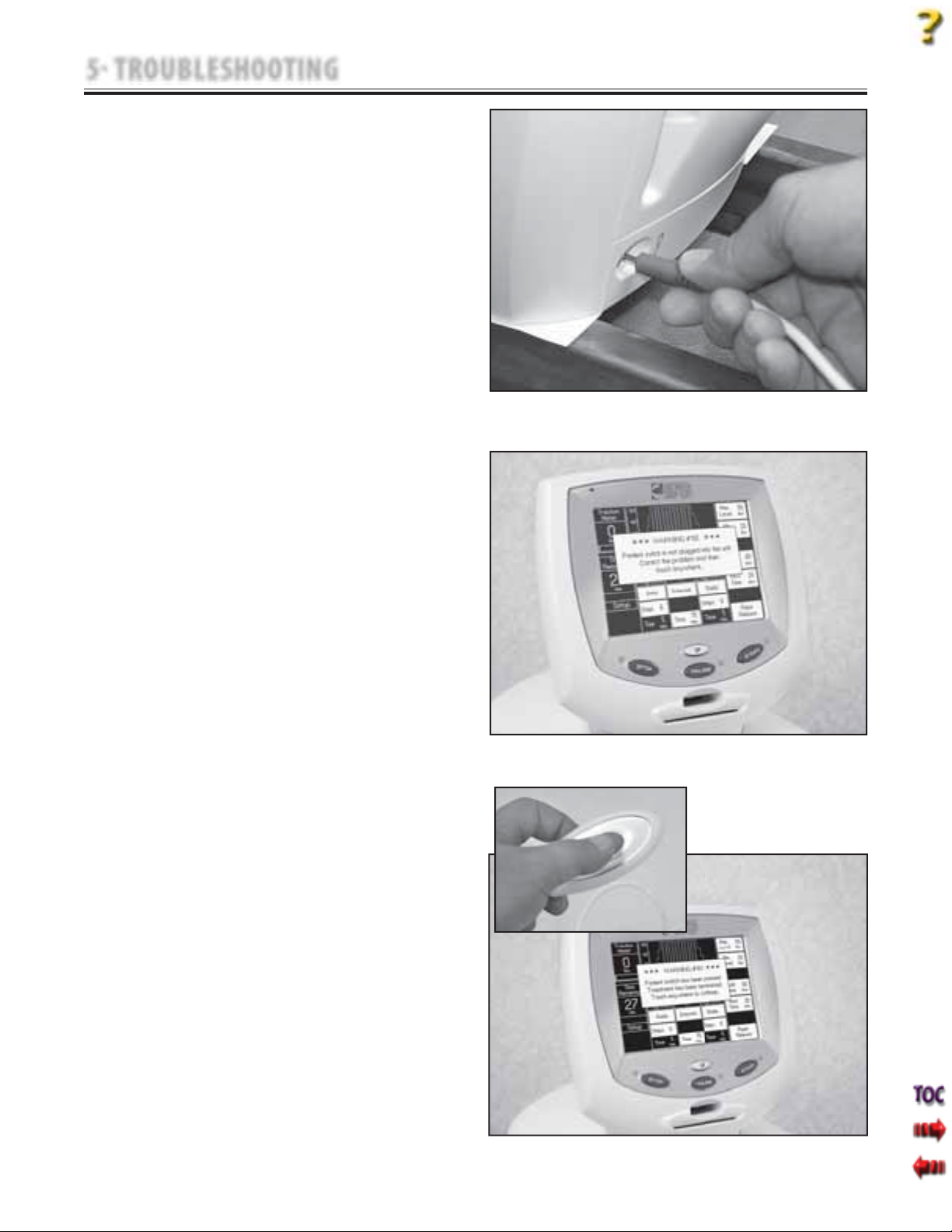
2. Connect Patient Interrupt Switch to unit
making certain it is completely seated in the
Patient Interrupt Switch connector. See
Figure 5.6.
3. Turn unit On with Power Switch. After unit
has completely booted up, disconnect the
Patient Interrupt Switch. Unit should display
Error 102. See Figure 5.7.
4. Reconnect the Patient Interrupt Switch. Touch
the Touch Screen anywhere to clear the Error.
5. Turn unit Off. with Patient Interrupt Switch
connected to the unit, turn unit On with
Power Switch.
6. After unit has completely booted up, depress
the Patient Interrupt Switch button. The unit
should display Error 101. Touch the Touch
Screen anywhere to clear the Error. See
Figure 5.8.
D. Test Result
1. If unit displays Errors 101 or 102 at the
respective test, unit passed test.
2. If unit does not display Errors 101 or 102 at
the respective test, unit failed test. Repeat
test with a known good Patient Interrupt
Switch.
3. If known good Patient Interrupt Switch
resolves the problem, replace existing Patient
Interrupt Switch with new part.
4. If the known good Patient Interrupt Switch
does not remedy the problem, Replace
Patient Interrupt Switch Jack.
Tru-Trac and TX® Therapeutic Traction Unit
FIGURE 5.6
FIGURE 5.7
17
FIGURE 5.8
Page 20
5 TROUBLESHOOTING
5.9 CORD RELEASE AND RETRACT TEST
A. Specification
Release . . . . . . . . . . . . . . . . . . . . Cord releases with less
than 5 lbs tension
Retract . . . . . . . . . . . . . . . . . .Cord completely retracts
B. Equipment Required
Calibration Fixture with calibrated Strain Meter.
C. Cord Release and Retract Test Procedures
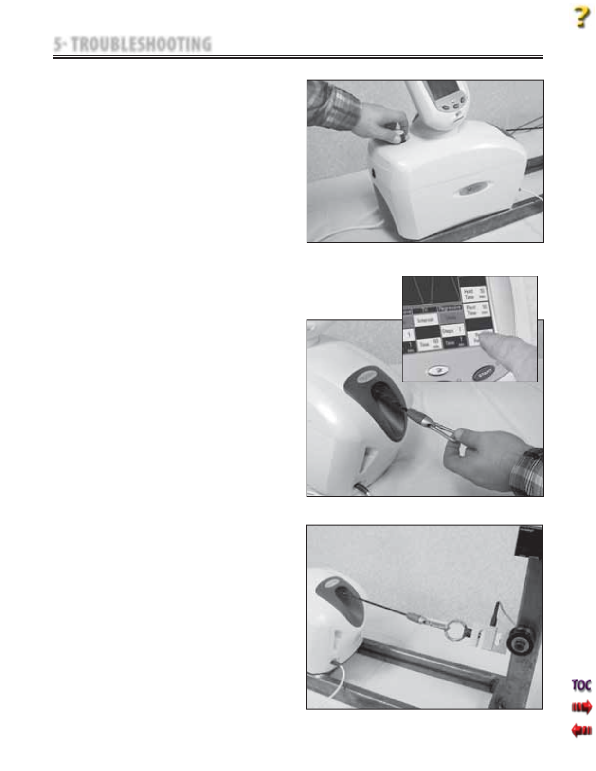
1. Secure unit to the Calibration Fixture. See
Figure 5.9.
2. Plug unit into approved power source and
turn unit On.
3. After unit has completely booted, press and
hold Rope Release on Touch Screen, and
pull Cord out. Release Rope Release while
holding Cord out. See Figure 5.10.
NOTE:
It may be necessary to pull and release slight tension
on the Cord to allow the internal mechanism to release
the stop on the Cord.
4. While holding on to extended Cord, press
Rope Release on the Touch Screen and
guide Cord back into unit.
5. Repeat step 3 above to connect the Cord to
the Calibration Fixture. See Figure 5.11.
6. Set up unit for a static pull of 100 lbs. Refer
to User Manual if necessary.
7. Press the START button. After the 100 lbs has
been reached, press the STOP Button
and view the Rope Release on the Touch
Screen, it should be inactive.
8. Watch as the tension decreases. Once the
tension decreases to below 5 lbs, the Rope
Release should become active. Immediately
press the Rope Release on the Touch Screen,
pull enough Cord out to facilitate
disconnection from the Calibration Fixture.
Release the Rope Release control.
Disconnect the Cord from the Calibration
Fixture.
NOTE:
It may be necessary to apply and release slight tension
on the Cord to allow the internal mechanism to release
the stop on the Cord.
9. Repeat step 4.
D. Test Result
1. If Cord fails to release, unit failed test.
Refer to 5.10 Cord Release
Troubleshooting.
2. If Cord fails to completely retract, unit
failed test. Adjust Cord Retraction Spring.
Refer to page 42 beginning with step 13
for adjustment procedures.
Tru-Trac and TX® Therapeutic Traction Unit
FIGURE 5.9
FIGURE 5.10
FIGURE 5.11
18
Page 21
5 TROUBLESHOOTING
5.10 CORD RELEASE TROUBLESHOOTING
A. Specification
Solenoid Supply Voltage . . . . . . . 24 VDC ±5%
Solenoid Gear . .Properly engages Driven Gear
B. Equipment Required
1. Digital Multimeter
2. #1 Phillips Screwdriver
3. 3/32 in Allen Wrench
4. Solenoid Assembly Mounting Jig
C. Cord Release Troubleshooting Procedure
1. Solenoid Assembly
a. Remove Side Covers. Refer to 6.1 Side
Cover Removal & Replacement.
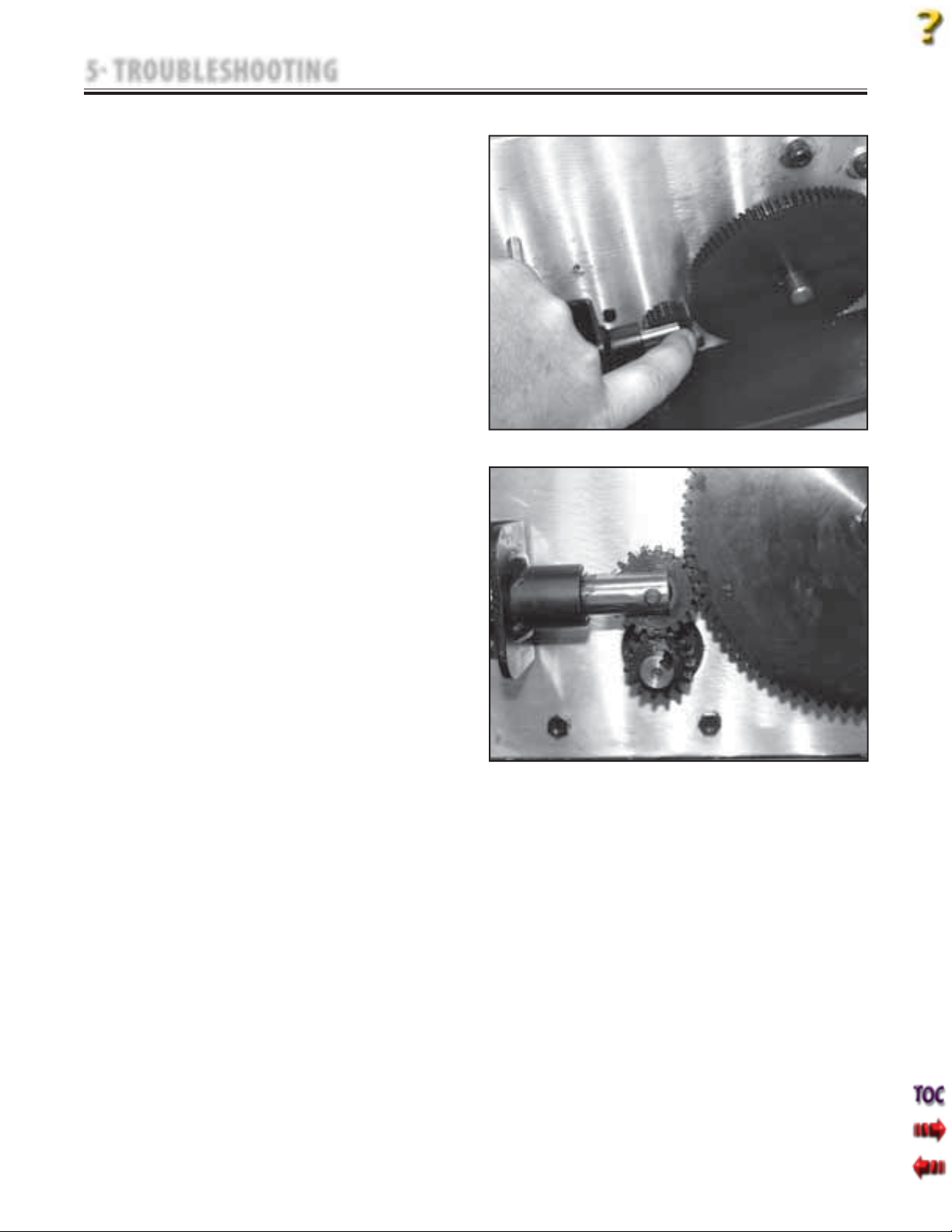
b. Manually move solenoid shaft in and out
to ensure gears are not locked and the
Solenoid Shaft moves and properly
engages the large Driven Gear. See
Figure 5.12. If Solenoid moves and
engages properly, procede to step c.
below.
If Solenoid Shaft will not move or
properly mesh with the Large Driven
Gear, adjust Solenoid Assembly. Refer
to page 46, parts A-D for adjustment. If
problem persists, replace Solenoid
Assembly. Refer to 6.11 Solenoid
Assembly Removal & Replacement
procedures.
c. With unit connected to an approved
power supply and turned on, press the
Rope Release on the Touch Screen.
Repeat several times to ensure the
solenoid properly engages and
disengages the large Driven Gear.
1) Touch Screen Control does not activate
Solenoid. Troubleshoot Motor Control
Board. Refer to page 20 for instructions.
2) Solenoid Gear does not properly
engage the large Driven Gear. See
Figure 5.13. Adjust Solenoid
Assembly. Refer to page 46, parts A
through D for adjustment.
Tru-Trac and TX® Therapeutic Traction Unit
FIGURE 5.12
FIGURE 5.13
19
Page 22
5 TROUBLESHOOTING
5.10 CORD RELEASE TROUBLESHOOTING (continued)
2. Motor Control Board
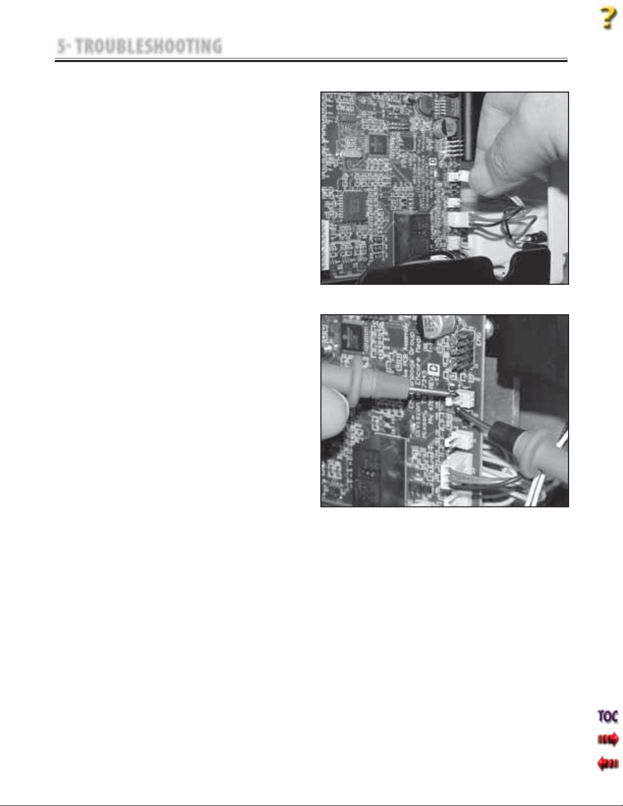
a. Disconnect Solenoid Harness from J8 on
Motor Control Board. See Figure 5.14.
b. Make certain unit is connected to an
approved power supply outlet and turn
unit On with Power Switch.
c. Set Multimeter to read 24 VDC and
connect leads to the J8 connector pins.
See Figure 5.15.
d. Push and hold the Rope Release on the
Touch Screen and take reading from
Multimeter.
1. If no voltage is present or low voltage
is present, replace Motor Control
Board. Refer to 6.5 Motor Control
Board Removal & Replacement.
2. If proper voltage is present and
problem persists, replace Touch
Screen Assembly. Refer to 6.6 Touch
Screen Removal & Replacement.
Tru-Trac and TX® Therapeutic Traction Unit
FIGURE 5.14
20
FIGURE 5.15
Page 23
5 TROUBLESHOOTING
5.11 LOAD CELL TEST
A. Specification
Touch Screen Reading ±10%
B. Equipment Required
1. Calibration Fixture with calibrated Load Cell
C. Load Cell Test Procedure
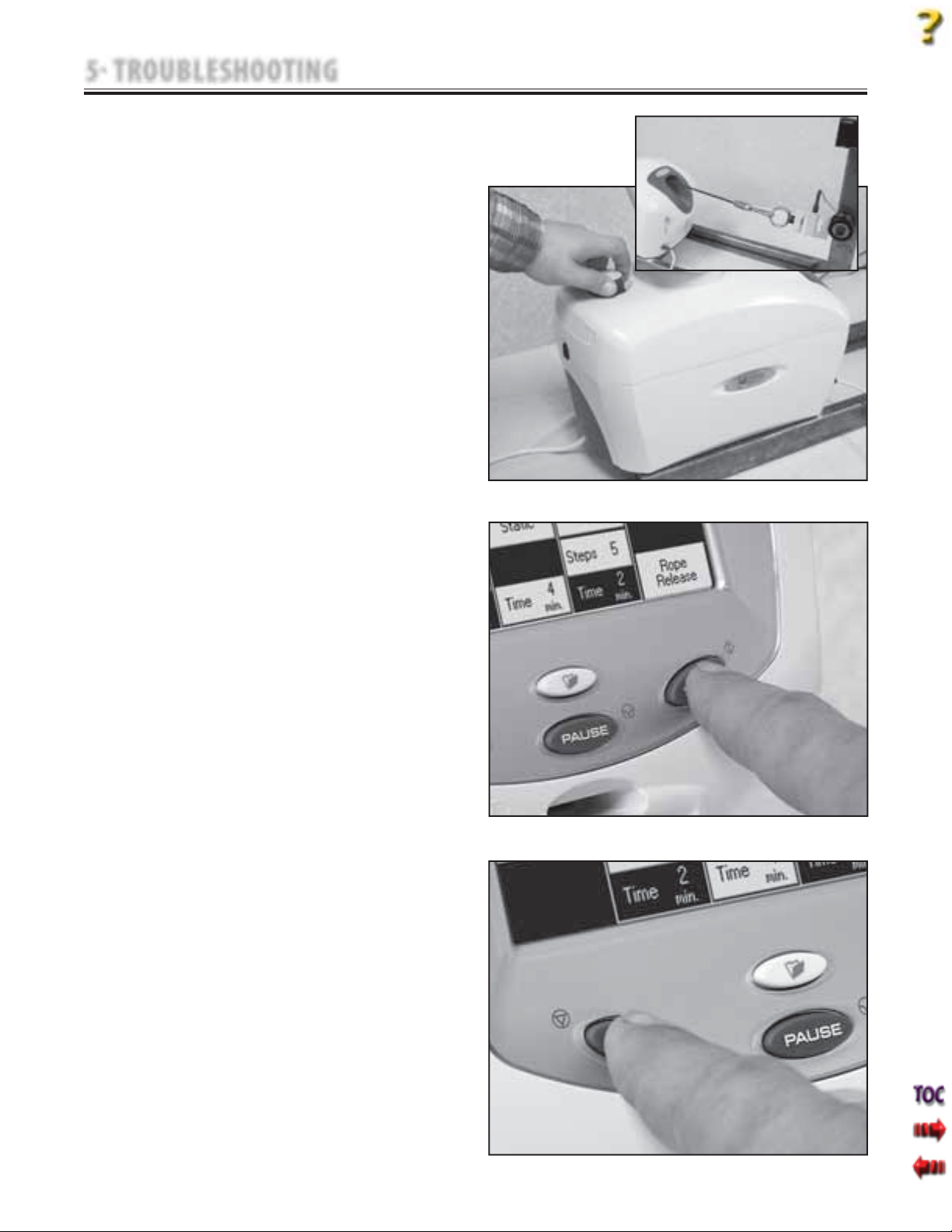
1. Secure unit to the Calibration Fixture. See
Figure 5.16.
2. Plug unit into an approved power source
and turn unit On with Power Switch.
3. After unit is completely booted, Press Cord
Release on the Touch Screen and pull out
enough Cord to connect Cord to
the Load Cell. See Figure 5.16.
4. After connecting Cord to Load Cell, allow
any slack Cord back into the unit. Release
the Rope Release on the Touch Screen.
5. Set up unit for a 100 lbs static pull. Refer to
User Manual if necessary.
6. Zero the Load Cell according to the
manufacturer's instructions.
7. Press the START button just below the Touch
Screen. See Figure 5.17.
8. During the pull, compare and record the
reading on the Touch Screen to the reading
on the Load Cell at 25, 50, 75, and 100 lb
intervals.
9. After 100 lbs has been reached, press the
STOP button. See Figure 5.18. Allow unit to
release the Cord.
D. Test Result
1. If reading of Load Cell is within ±10% of the
Touch Screen reading, unit passed test.
2. If readings are higher or lower than the
±10% tolerance, unit failed test. Calibrate
unit and re-test. Refer to Section 7
Calibration for Procedures.
3. If problem persists, perform Load
Cell Troubleshooting. Refer to 5.12 Load Cell
Troubleshooting for procedures.
Tru-Trac and TX® Therapeutic Traction Unit
FIGURE 5.16
FIGURE 5.17
21
FIGURE 5.18
Page 24
5 TROUBLESHOOTING
5.12 LOAD CELL TROUBLESHOOTING
A. Specification
Voltage to Load Cell . . . . . . . . . . . . . . . . . .10 VDC
Voltage from Load Cell . . . . . . . . . . . . . . Variable
Motor Control Board Voltage (U3) . . . Variable
B. Equipment Required
1. Calibration Fixture with calibrated Load Cell
2. 3/32 in Allen Wrench
3. Digital Multimeter
4. Pick for removing wires from connectors.
C. Voltage to Load Cell Test
1. Remove Side Covers. Refer to 6.1 Side
Cover Removal & Replacement.
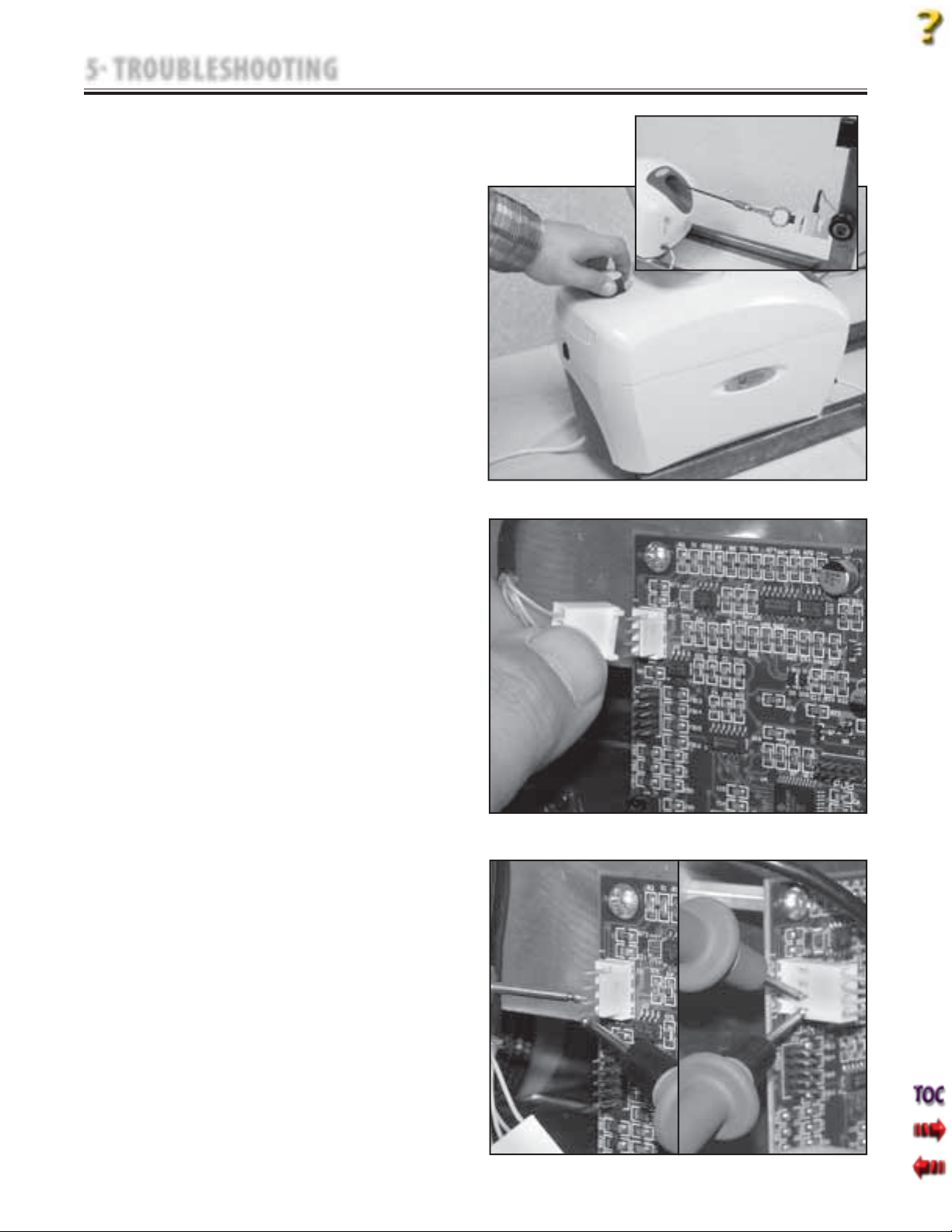
2. Secure unit to the Calibration Fixture. See
Figure 5.19.
3. Plug unit into an approved power source
and turn unit On with Power Switch.
4. After unit is completely booted, press Cord
Release on the Touch Screen and pull out
enough Cord to connect Accessory Clip to
the Load Cell. See Figure 5.19.
5. Guide any Cord slack back into unit.
Release the Rope Release on the Touch
Screen.
6. Remove Load Cell Connector from J11 on
Motor Control Board. See Figure 5.20.
7. Set Multimeter to read 10 VDC and
connect leads to Pins 1 and 2 of the J11
connector on the Motor Control Board.
See Figure 5.21.
8. Multimeter should read 10 VDC.
If reading is 10 VDC, procede to step 9.
If reading is not 10 VDC, replace Motor
Control Board. Refer to 6.5 Motor Control
Board Removal & Replacement.
9. Reconnect Load Cell Connector to J11 on
Motor Control Board. Make certain the
Pink Wire on the Connector is positioned
onto Pin 1 of the Motor Control Board. See
Figure 5.22.
10. Set Multimeter to read 10 VDC. Make
connection with Pins 1 and 2 from the
side of the connector with Multimeter
Leads and take reading. See Figure 5.22.
11. If reading is not 10 VDC, replace unit Load
Cell. Refer to 6.7 Load Cell Removal and
Replacement. If reading is 10 VDC procede
to step D.
Tru-Trac and TX® Therapeutic Traction Unit
FIGURE 5.19
FIGURE 5.20
22
FIGURE 5.21
FIGURE 5.22
Page 25
5 TROUBLESHOOTING
5.12 LOAD CELL TROUBLESHOOTING (continued)
D. Voltage from Load Cell Tests
NOTE:
It will be necessary to have two people available for
the following test.
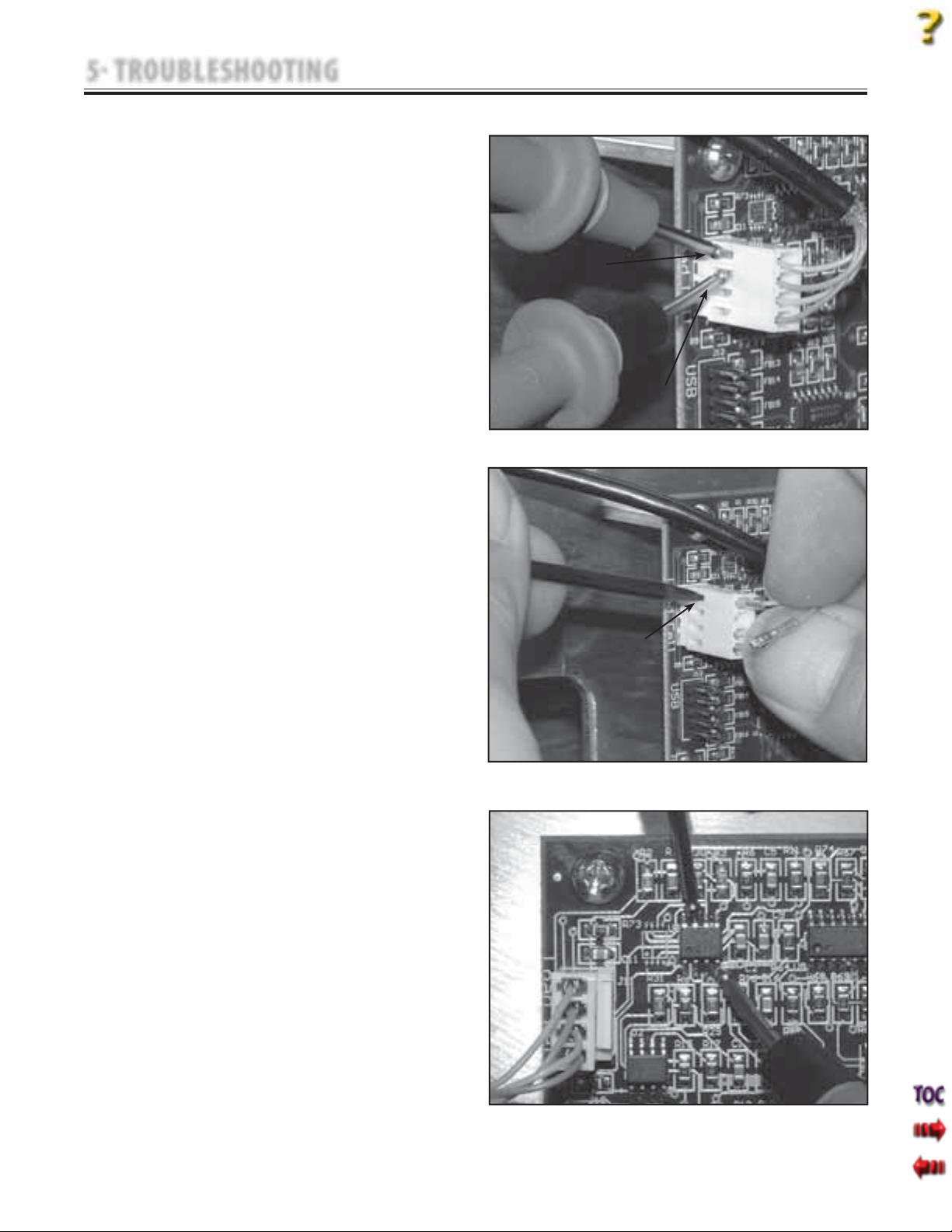
1. Set Multimeter to read 10 VDC. Make
connection with Pin 3 (Blue wire) and Pin 4
(Green wire) from the side of the
connector with Multimeter Leads. See
Figure 5.23.
2. Press the START button. The voltage
reading on Multimeter should increase as
Cord Tension increases.
3. Press the STOP button. The voltage reading
on Multimeter should decrease as Cord
Tension decreases.
4. If voltage does not increase and decrease
as described in steps 2 and 3, continue
with test.
5. Turn unit Off. Using the Pick, remove Blue
wire and Green wire from connector. See
Figure 5.24.
6. Connect the Multimeter Leads to the Blue
and Green wires. Repeat steps 2 and 3.
7. If voltage does not increase or decrease as
described in steps 2 and 3, replace unit
Load Cell. Refer to 6.7 Load Cell Removal
and Replacement.
8. If voltage does increase and decrease as
described in steps 2 and 3, replace wires
into connector. Make certain the Blue wire
is in the Pin 3 position and the Green wire
is in the Pin 4 position. Repeat steps 2 and
3. If problem persists, proceed to step 9.
9. Locate U3 on Motor Control Board.
Connect the Red (+) Multimeter Lead to
Pin 7 of U3 and the Black (-) Lead to Pin 4
of U3. See Figure 5.25.
10. Repeat steps 2 and 3. If voltage does not
increase and decrease as described in
steps 2 and 3, replace Motor Control
Board. Refer to 6.5 Motor Control Board
Removal & Replacement.
Tru-Trac and TX® Therapeutic Traction Unit
RED LEAD
TO PIN 4
BLACK LEAD
TO PIN 3
FIGURE 5.23
USE PICK TO
REMOVE WIRES
FIGURE 5.24
23
FIGURE 5.25
Page 26
5 TROUBLESHOOTING
5.13 TOUCH SCREEN TEST
A. Specification
Contrast Control . . . . . . . . . . Touch Screen Dims
and Brightens
Touch Screen . . . . . . . . . Displays proper Screen
B. Equipment Required
None
C. Touch Screen Test Procedure
1. Place unit on level work surface.
2. Plug Power Cord into grounded power
source with appropriate voltage. See
Specifications on page 8.
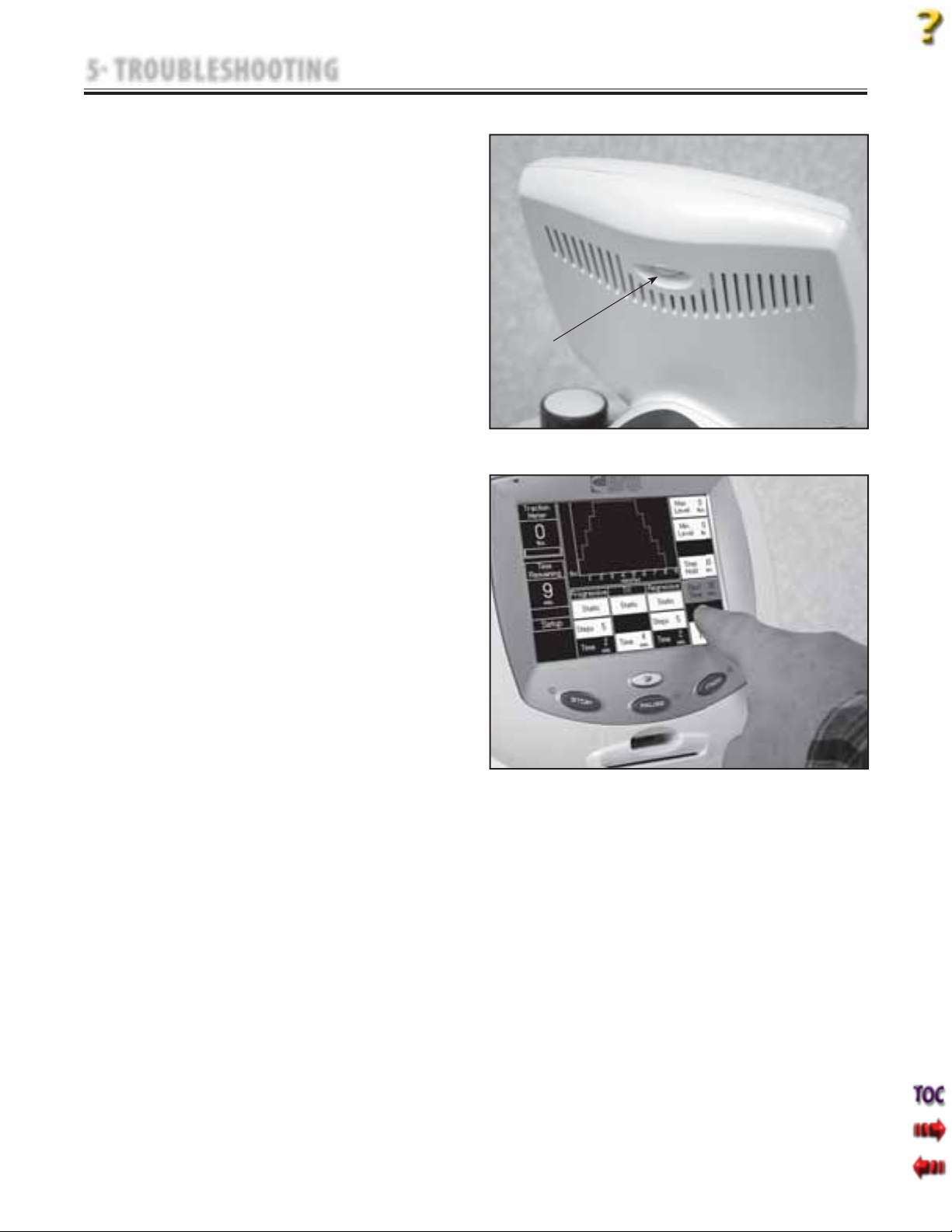
3. Turn unit On with Power Switch. After the
unit has completely booted, adjust the
Touch Screen Contrast with the Contrast
Control on the back of the Touch Screen
Housing. See Figure 5.26.
4. Press Touch Screen controls to verify the
Touch Screen responds and displays the
correct screen. See Figure 5.27.
D. Test Result
1. If when adjusting, Contrast Control dims
and brightens Touch Screen, unit passed
test. If Contrast Control does not dim and
brighten Touch Screen, refer to 5.14 Touch
Screen Troubleshooting.
2. If when pressing controls on Touch Screen
the proper screen does not display,
unit failed test. Calibrate Touch Screen. Refer
to 7.2 Touch Screen Calibration.
3. If nothing is visible on Touch Screen, adjust
Contrast Control. If problem persists, unit
failed test. Refer to 5.14 Touch Screen
Troubleshooting.
Tru-Trac and TX® Therapeutic Traction Unit
CONTRAST
KNOB
FIGURE 5.26
FIGURE 5.27
24
Page 27
5 TROUBLESHOOTING
Tru-Trac and TX® Therapeutic Traction Unit
5.14 TOUCH SCREEN TROUBLESHOOTING
A. Specification
Voltage to Touch Screen:
J6 Connector . . . . . . . . . . . . . . . . .5 VDC ±5%
Display Connector . . . . . . . . . . .24 VDC ±5%
B. Equipment Required
1. 3/32 in Allen Wrench
2. Digital Multimeter
C. Touch Screen Troubleshooting Procedure
1. Remove Side Covers. Refer to 6.1 Side Cover
Removal & Replacement.
2. Plug unit into an approved power source
and turn unit On with Power Switch.
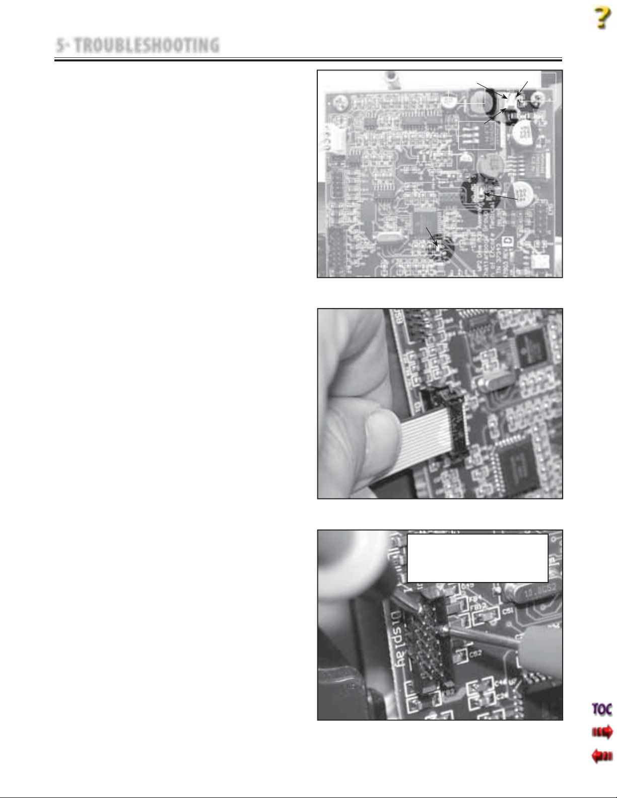
3. Observe Motor Control Board LEDs. The
"5V OK" LED should be illuminated and
LED 3 should be flashing. See Figure 5.28.
a. If LEDs are not working properly, proceed
to step 4.
b. If LEDs are working properly, proceed to
steps 5 through 9.
4. Turn unit Off. Remove Touch Screen Ribbon
Cable from "Display" on Motor Control
Board. See Figure 5.29. Turn unit On.
a. If LEDs begin working properly, replace
Touch Screen assembly. Refer to 6.6
Touch Screen Assembly Removal and
Replacement.
b. If LEDs are not working properly, refer to
5.15 Power Supply Troubleshooting.
c. If Power Supply is functioning properly,
replace Motor Control Board. Refer to 6.5
Motor Control Board Removal and
Replacement.
5. Turn unit Off. Remove Touch Screen Ribbon
Cable from "Display" on Motor Control
Board. See Figure 5.29. Turn unit On.
6. Set Multimeter to VDC. On Connector J6,
connect the Red (+) Multimeter Lead to
Pin 1 and the Black (-) Lead to Pin 2. See
Figure 5.28. Take reading from Multimeter.
Reading should be +5 VDC.
7. Connect the Red (+) Multimeter Lead to Pin
6 and the Black (-) Lead to Pin 1 on the
Motor Control Board "Display" Connector.
See Figure 5.30 reading on Multimeter
should be 24 VDC.
8. If the voltage reads correctly from steps
5 and 6, replace the Touch Screen Assembly.
Refer to 6.6 Touch Screen Removal
and Replacement.
9. If either of the voltages are not reading
properly as in steps 6 and 7, replace Motor
Control Board. Refer to 6.5 Motor Control
Board Removal & Replacement.
PIN 1
J6
LED 3
PIN 2
5V OK LED
FIGURE 5.28
FIGURE 5.29
Make certain Multimeter Leads are on the
correct pins and do not short across any
other pins to prevent destruction of the
CAUTION
Motor Control Board.
FIGURE 5.30
25
Page 28
5 TROUBLESHOOTING
5.15 POWER SUPPLY TROUBLESHOOTING
A. Specification
Power Supply Input . . 100 V-240 V (50/60 Hz)
Power Supply Output . . . . . . . . . . .24 VDC ±5%
B. Equipment Required
1. 3/32 in Allen Wrench
2. Digital Multimeter
C. Power Supply Troubleshooting Procedure
1. Remove Side Covers. Refer to 6.1 Side Cover
Removal & Replacement.
2. Plug Power Cord into grounded power
source with appropriate voltage. See
Specifications on page 8.
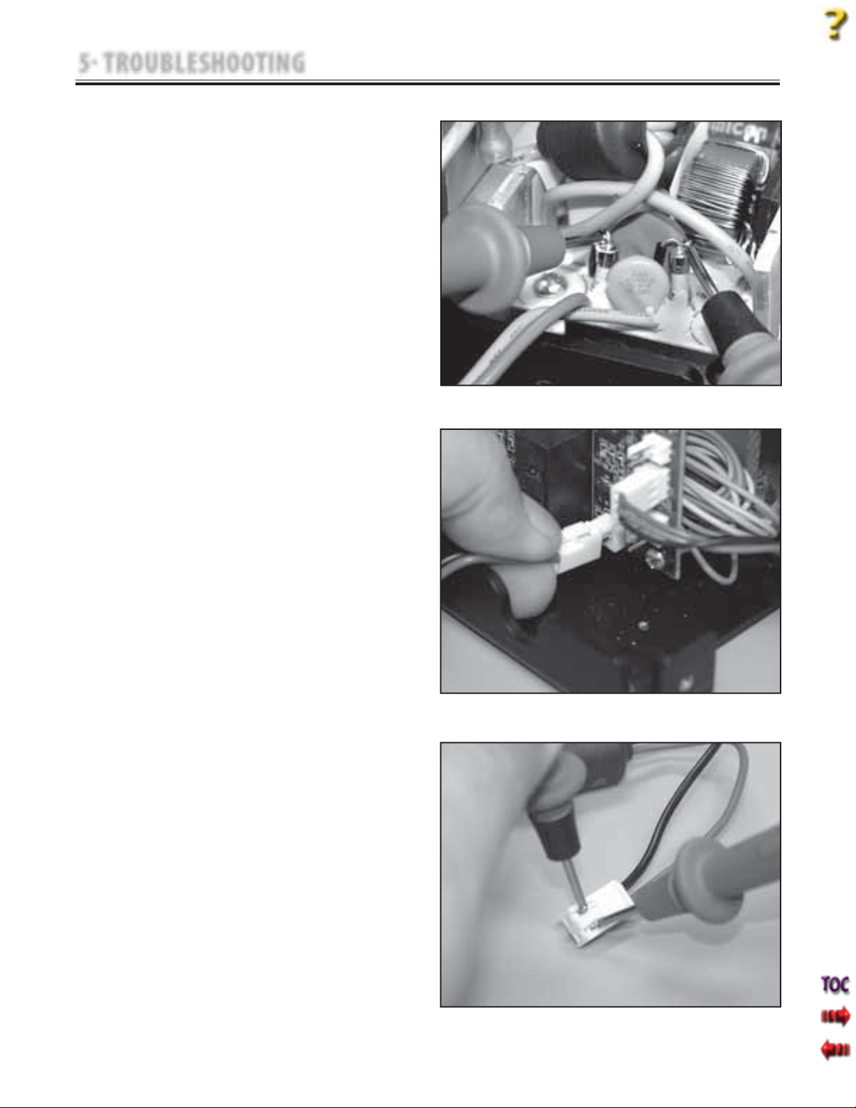
3. Set Multimeter to read appropriate VAC.
4. Connect Multimeter Leads to the Power
Supply Fuses at the rear of Power Supply.
See Figure 5.31. Multimeter should read
same voltage as the approved power
source.
a. If reading is the same as approved power
source, proceed to step 5.
b. If VAC reading is not the same as
approved power source, replace Power
Supply. Refer to 6.12 Power Supply
Removal & Replacement.
5. Remove Power Supply Output Harness from
Motor Control Board J5. See Figure 5.32.
6. Set Multimeter to read VDC. Connect
Multimeter Leads to the Power Supply
Output Harness. See Figure 5.33. Multimeter
reading should be 24 VDC ±5%.
a. If reading is within the specified range as
stated above, unit passed test.
b. If reading is not within the specified
range as stated above, replace Power
Supply. Refer to 6.12 Power Supply
Removal & Replacement.
Tru-Trac and TX® Therapeutic Traction Unit
FIGURE 5.31
FIGURE 5.32
26
FIGURE 5.33
Page 29
6 REMOVAL & REPLACEMENT
6.1 SIDE COVER REMOVAL & REPLACEMENT
Unplug the unit from the power source before
attempting removal or replacement procedures to
prevent electrical shock.
A. Part Numbers
Side Cover (2 Req'd) . . . . . . . . . . . . . . . . . . . 47857
B. Equipment Required
3/32 in Allen Wrench
•
Flat Blade Screwdriver
•
#1 Phillips Screwdriver
•
C. Removal of Side Covers
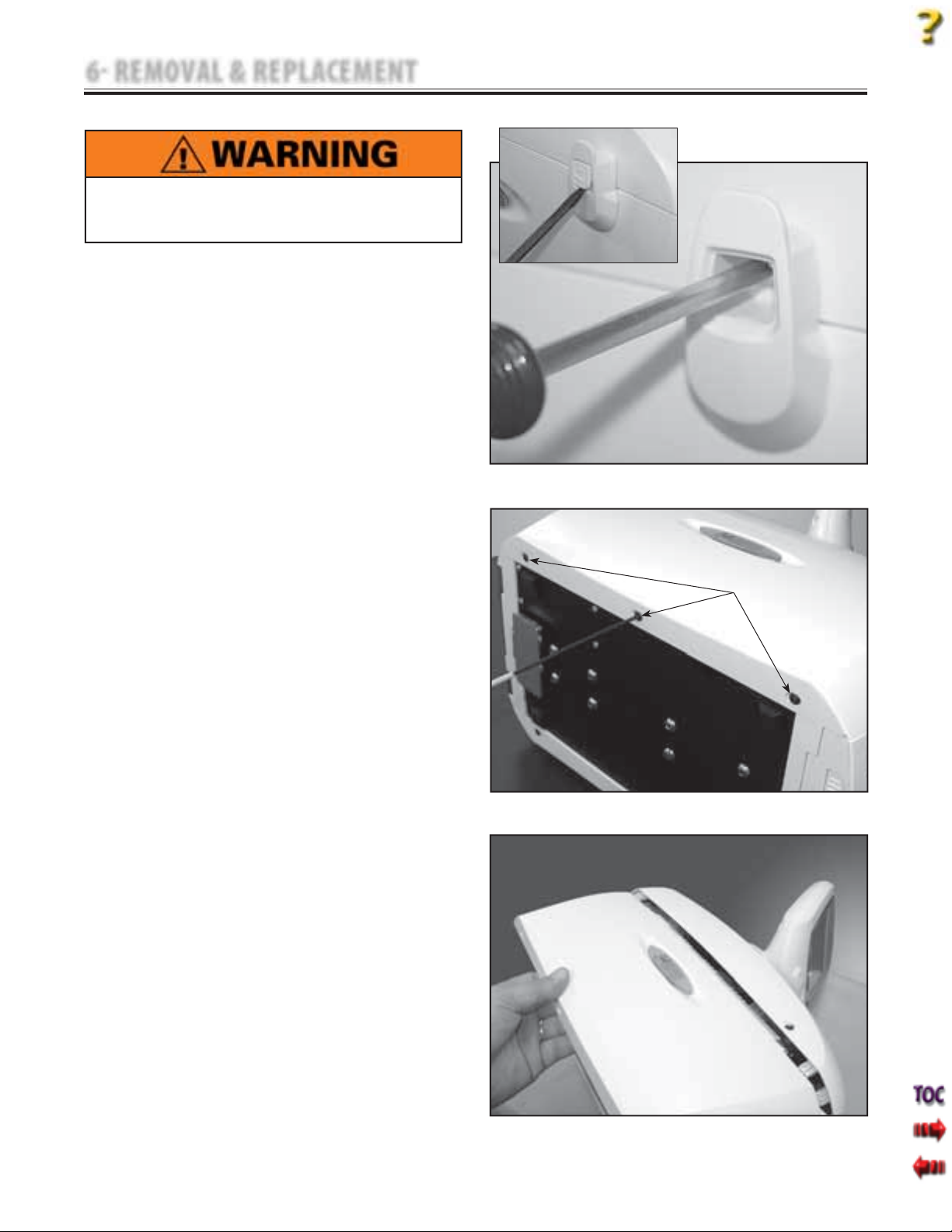
1. Remove Patient Interrupt Switch Hook
Screw Cover with a Flat Blade Screwdriver.
See inset at Figure 6.1.
2. Remove Patient Interrupt Switch Hook
Screw using a #1 Phillips Screwdriver. See
Figure 6.1.
3. Lay unit on its side on a clean, soft work
surface.
4. Using the 3/32 in Allen Wrench, remove the
three Side Cover Mounting Screws from the
bottom of the unit. See Figure 6.2.
5. Slide side cover from under Top Cover.
6. Turn unit over onto opposite side and
repeat steps 2-5.
D. Replacement of Side Covers
1. Position Side Cover Top Mounting Tab
between plastic of Top Cover and Touch
Screen Mounting Plate. See Figure 6.3.
2. Slide cover into position and secure with
three socket head screws using the 3/32 in
Allen Wrench. Refer to Figure 6.2.
NOTE:
Do not overtighten mounting screws.
Tru-Trac and TX® Therapeutic Traction Unit
FIGURE 6.1
SIDE COVER
MOUNTING SCREWS
FIGURE 6.2
27
FIGURE 6.3
Page 30
6 REMOVAL & REPLACEMENT
6.2 TOP AND CORD GUIDE COVER REMOVAL & REPLACEMENT
Tru-Trac and TX® Therapeutic Traction Unit
Unplug the unit from the power source before
attempting removal or replacement procedures to
prevent electrical shock.
A. Part Numbers
•
Top Co ver . . . . . . . . . . . . . . . . . . . . . . . . . . . . 47856
•
Cord Guide Cover . . . . . . . . . . . . . . . . . . . . 47872
B. Equipment Required
•
3/32 in Allen Wrench
•
#2 Phillips Screwdriver
•
Touch Screen to Cover Assembly Jig
C. Removal of Top and Cord Guide Covers
1. Remove Side Covers. Refer to 6.1 Side Cover
Removal & Replacement.
2. Position unit upright on base and untie
Traction Cord from Knuckle. Refer to
page 41, step 11 Traction Cord Removal &
Replacement.
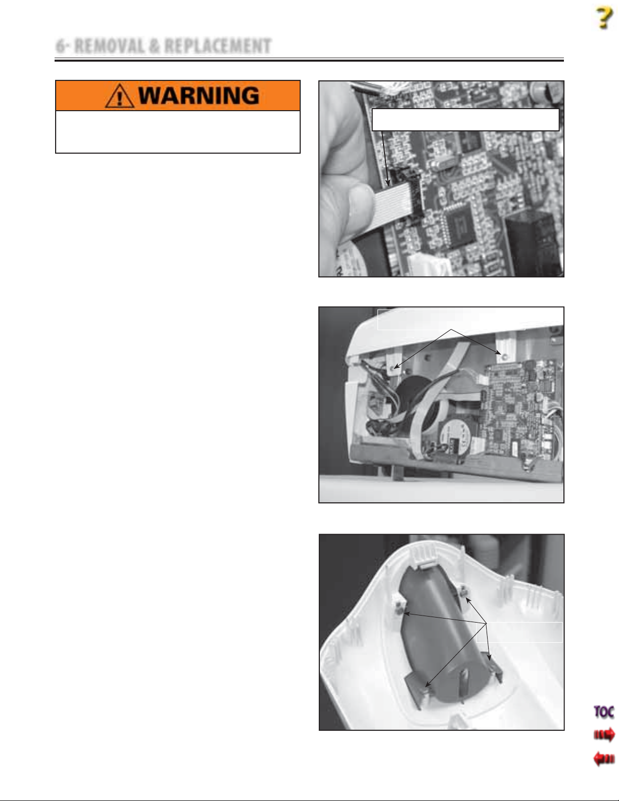
3. Disconnect the Touch Screen Ribbon
Cable from the Motor Control Board. See
Figure 6.4.
4. Using the #1 Phillips Screwdriver, remove
the two Top Cover Mounting Screws from
each side of the unit. See Figure 6.5.
NOTE:
To remove the Touch Screen Assembly from the
Top Cover refer to 6.6 Touch Screen Removal &
Replacement.
5. Carefully lift the Top Cover away from unit
and position into Touch Screen to Cover
Assembly Jig. See Figure 6.6.
6. Using the #2 Phillips Screwdriver, remove
the four Cord Guide Cover Mounting
Screws. See Figure 6.6.
D. Replacing Top and Cord Guide Covers
1. With Top Cover positioned onto the Touch
Screen to Cover Assembly Jig, place the
Cord Guide Cover into position. Secure with
the four Cord Guide Cover Mounting
Screws. See Figure 6.6.
2. Position the Top Cover Assembly onto the
unit chassis. Secure into position on the
standoffs with the four Top Cover Mounting
Screws (two on each side). See Figure 6.5.
3. Connect the Touch Screen Ribbon Cable to
the "Display" Connector on the Motor
Control Board. See Figure 6.4.
4. Install Side Covers. Refer to 6.1 Side Cover
Removal & Replacement.
WHEN INSTALLING, RIBBON CABLE BLACK STRIP MUST BE
TOWARD THE TOP OF THE MOTOR CONTROL BOARD.
FIGURE 6.4
TOP COVER MOUNTING SCREWS
TWO ON EACH SIDE
FIGURE 6.5
CORD GUIDE COVER
MOUNTING SCREWS
FIGURE 6.6
28
Page 31
6 REMOVAL & REPLACEMENT
6.3 REAR COVER REMOVAL & REPLACEMENT
Unplug the unit from the power source before
attempting removal or replacement procedures to
prevent electrical shock.
A. Part Numbers
Rear Cover Assembly . . . . . . . . . . . . . . . . . .48110
B. Equipment Required
3/32 in Allen Wrench
•
Touch Screen to Cover Assembly Jig
•
C. Removal of Top and Cord Guide Covers
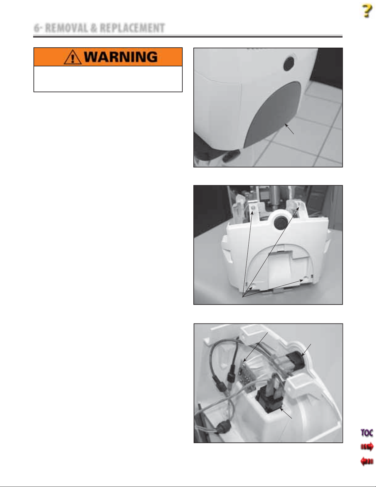
1. Remove IEC Connector Cover. See
Figure 6.7.
2. Remove Side Covers. Refer to 6.1 Side Cover
Removal & Replacement.
3. Remove Top Cover Assembly. Refer to 6.2,
part C, steps 1-5.
4. Using the 3/32 in Allen Wrench, remove
the four Rear Cover Mounting Screws. See
Figure 6.8.
NOTE:
To replace the Rear Cover with a new part, remove the
Power Switch, Mains Connector, and USB Board from
the old Rear Cover for re-installation onto the new
part. See Figure 6.9.
It is not necessary to remove Harnesses from Power
Switch, Mains Connector, or USB Board unless these
components are to be replaced.
D. Replacing Rear Cover
1. Replace existing Rear Cover
a. Secure Rear Cover to chassis with four
Rear Cover Mounting Screws. See
Figure 6.8.
b. Install Top Cover Assembly. Refer to 6.2,
part D, steps 2 and 3.
c. Install Side Covers. Refer to 6.1, part D,
steps 1 and 2.
2. Replace with new Rear Cover
a. Install existing Power Switch, Mains
Connector, and USB Board to new Rear
Cover.
b. Secure Rear Cover to chassis. See
Figure 6.8.
c. Install Top Cover Assembly. Refer to 6.2,
part D, steps 2 and 3.
d. Install Side Covers. Refer to 6.1, part D,
steps 1 and 2.
NOTE:
Do not overtighten mounting screws.
Tru-Trac and TX® Therapeutic Traction Unit
IEC CONNECTOR COVER
FIGURE 6.7
REAR COVER
MOUNTING SCREWS
FIGURE 6.8
USB BOARD
POWER SWITCH
MAINS CONNECTOR
FIGURE 6.9
29
Page 32
6 REMOVAL & REPLACEMENT
6.4 FRONT COVER REMOVAL & REPLACEMENT
Tru-Trac and TX® Therapeutic Traction Unit
Unplug the unit from the power source before
attempting removal or replacement procedures to
prevent electrical shock.
A. Part Numbers
Front Cover . . . . . . . . . . . . . . . . . . . . . . . . . . . .47858
B. Equipment Required
3/32 in Allen Wrench
•
Touch Screen to Cover Assembly Jig
•
Needle Nose Pliers
•
C. Removal of Front Cover
1. Remove Side Covers. Refer to 6.1 Side Cover
Removal & Replacement.
2. Remove Top Cover Assembly. Refer to 6.2,
part C, steps 2-5.
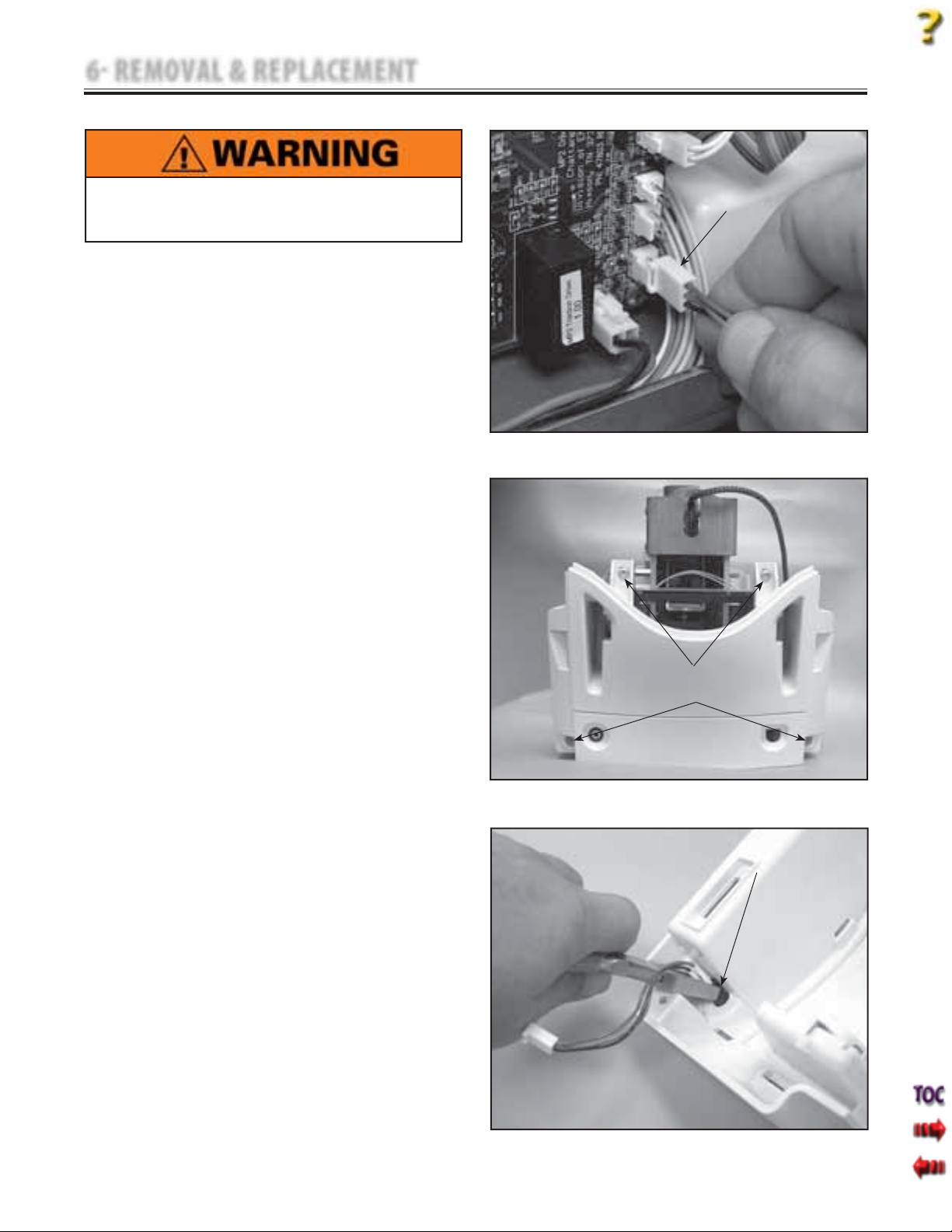
3. Disconnect the Patient Interrupt Switch
Jack from the Motor Control Board. See
Figure 6.10.
4. Using the 3/32 in Allen Wrench, remove
the four Front Cover Mounting Screws. See
Figure 6.11.
NOTE:
To replace the Front Cover with a new part, remove
the Patient Interrupt Switch Jack from the old Front
Cover for re-installation onto the new part. See
Figure 6.12.
D. Replacing Front Cover
1. Replacing existing Front Cover
a. Connect Patient Interrupt Switch Jack to
the Motor Control Board. See Figure 6.10.
b. Secure the Front Cover to the chassis
with the four Front Cover Mounting
Screws. See Figure 6.11.
c. Install Top Cover Assembly. Refer to 6.2,
part D, steps 2 and 3.
d. Install Side Covers. Refer to 6.1, part D,
steps 1 and 2.
2. Replacing with new Front Cover
a. Install Patient Interrupt Switch Jack into
new Front Cover. See Figure 6.12.
b. Perform steps 3-4 above in reverse order.
c. Install Top Cover Assembly. Refer to 6.2,
part D, steps 2 and 3.
d. Install Side Covers. Refer to 6.1, part D,
steps 1 and 2.
NOTE:
Do not overtighten mounting screws.
PATIENT INTERRUPT
SWITCH HARNESS
FIGURE 6.10
FRONT COVER
MOUNTING SCREWS
FIGURE 6.11
PATIENT INTERRUPT
SWITCH JACK
FIGURE 6.12
30
Page 33
6 REMOVAL & REPLACEMENT
Tru-Trac and TX® Therapeutic Traction Unit
The remaining removal and replacement procedures in this section require that the following be performed
after component or assembly replacement to ensure proper alignment and operation of the unit:
1. COMPLETE CALIBRATION OF UNIT
AND
2. MINIMUM OF 2 HOUR BURN IN OF UNIT AFTER SUCCESSFUL CALIBRATION
Failure to perform either of these procedures after a component or assembly replacement will void warranty
and may result in injury to patients and severe equipment damage.
31
Page 34
6 REMOVAL & REPLACEMENT
6.5 MOTOR CONTROL BOARD REMOVAL & REPLACEMENT
Tru-Trac and TX® Therapeutic Traction Unit
Unplug the unit from the power source before
attempting removal or replacement procedures to
prevent electrical shock.
A. Part Numbers
Motor Control Board . . . . . . . . . . . . . . . . . .47803
B. Equipment Required
3/32 in Allen Wrench
•
#2 Phillips Screwdriver
•
C. Removal of Motor Control Board
1. Remove Side Covers. Refer to 6.1 Side Cover
Removal & Replacement.
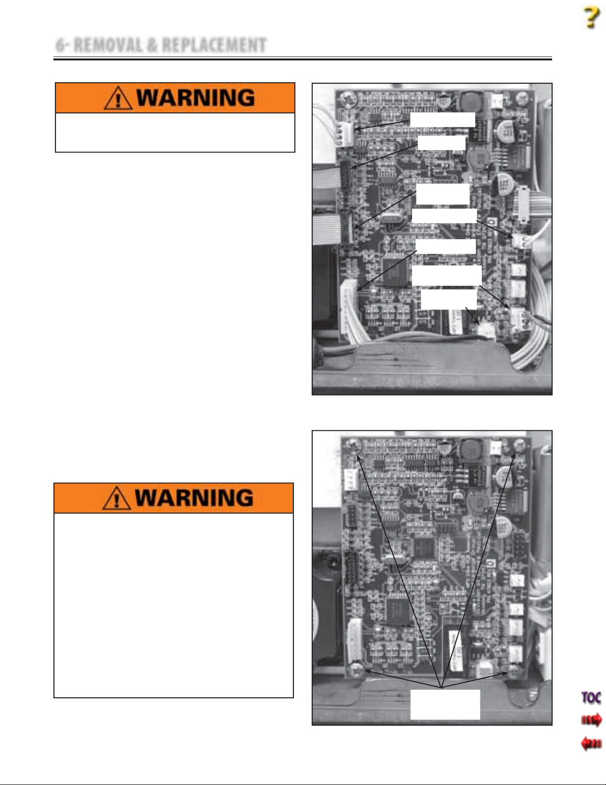
2. Disconnect all seven harnesses from the
Motor Control Board. See Figure 6.13.
3. Using the #2 Phillips Screwdriver, remove
the four Motor Control Board Mounting
Screws. See Figure 6.14.
D. Replacing Motor Control Board
1. Position Motor Control Board over chassis
standoffs and secure into position with the
screws removed in step 3 above.
2. Install Harnesses to the Motor Control
Board. See Figure 6.13.
3. Perform complete Calibration and Burn In
of unit.
NOTE:
Do not overtighten mounting screws.
LOAD CELL HARNESS
USB HARNESS
TOUCH SCREEN
HARNESS
SOLENOID HARNESS
MOTOR HARNESS
PATIENT INTERRUPT
SWITCH HARNESS
POWER SUPPLY
HARNESS
FIGURE 6.13
This component removal and replacement
procedure requires that the following be performed
after component or assembly replacement to ensure
proper alignment and operation of the unit:
COMPLETE CALIBRATION OF UNIT Refer to
Section 7
AND
MINIMUM OF 2 HOUR BURN IN OF UNIT AFTER
SUCCESSFUL CALIBRATION Refer to Section 7
Failure to perform either of these procedures, after
a component or assembly replacement will void
warranty and may result in injury to patients and/or
severe equipment damage.
MOTOR CONTROL
BOARD MOUNTING
SCREWS
FIGURE 6.14
32
Page 35
6 REMOVAL & REPLACEMENT
6.6 TOUCH SCREEEN ASSEMBLY REMOVAL & REPLACEMENT
Tru-Trac and TX® Therapeutic Traction Unit
Unplug the unit from the power source before
attempting removal or replacement procedures to
prevent electrical shock.
A. Part Numbers
Touch Screen Assembly . . . . . . . . . . . . . . .48063
B. Equipment Required
3/32 in Allen Wrench
•
Flat Blade Screwdriver
•
Touch Screen to Cover Assembly Jig
•
C. Removal of Touch Screen Assembly
1. Remove Side Covers. Refer to 6.1 Side Cover
Removal & Replacement.
2. Remove the Top Cover. Refer to 6.2 Top and
Cord Guide Cover Removal & Replacement,
part C, steps 2-5.
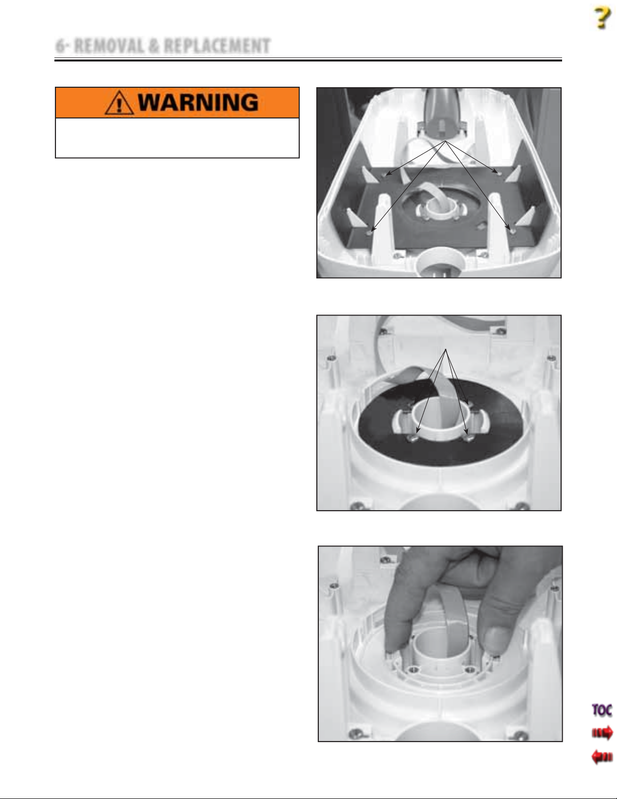
3. Using the Flat Blade Screwdriver, remove
the four Top Moulding Plate Mounting
Screws. When removing the Top Moulding
Plate, guide the Touch Screen Ribbon Cable
through the opening. See Figure 6.15.
4. Using the Flat Blade Screwdriver, remove
the four Turn Table Plate Retaining Screws.
See Figure 6.16.
5. Squeeze the two Touch Screen Assembly
Tabs and push the Touch Screen Assembly
out of the Top Cover. See Figure 6.17.
TOP MOULDING PLATE
MOUNTING SCREWS
FIGURE 6.15
TURN TABLE PLATE
MOUNTING SCREWS
33
FIGURE 6.16
FIGURE 6.17
Page 36
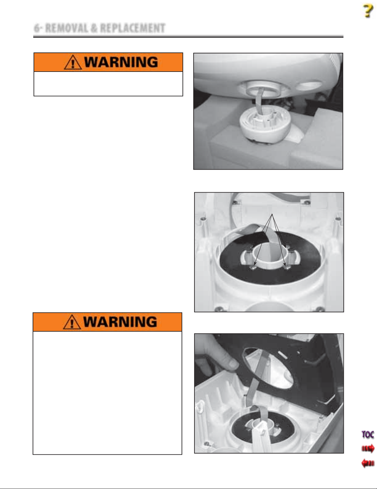
6 REMOVAL & REPLACEMENT
6.6 TOUCH SCREEN ASSEMBLY REMOVAL & REPLACEMENT (continued)
Unplug the unit from the power source before
attempting removal or replacement procedures to
prevent electrical shock.
D. Replacing Touch Screen Assembly
1. Place new Touch Screen Assembly into
Touch Screen to Cover Assembly Jig.
2. Position Top Cover over the Touch Screen
Assembly aligning the mounting hole to the
Touch Screen Assembly.
3. Slide the Top Cover over the Touch Screen
Assembly until the Mounting Tabs click into
position. See Figure 6.18.
4. Position the Turntable Plate and secure the
four screws with the #2 Phillips Screwdriver.
See Figure 6.19.
5. Position the Top Moulding Plate. Thread the
Touch Screen Ribbon Cable through the
opening in the Top Moulding Plate as
shown in Figure 6.20. Secure the four Top
Moulding Plate screws with the #2 Phillips
Screwdriver. Refer to Figure 6.15.
6. Install Top Cover Assembly. Refer to 6.2,
part D, steps 2 and 3.
7. Install Side Covers. Refer to 6.1, part D,
steps 1 and 2.
8. Perform complete Calibration and Burn In
of unit.
NOTE:
Do not overtighten mounting screws.
FIGURE 6.18
Tru-Trac and TX® Therapeutic Traction Unit
TURN TABLE PLATE
MOUNTING SCREWS
This removal and replacement procedure requires
that the following be performed after component or
assembly replacement to ensure proper alignment
and operation of the unit:
1. COMPLETE CALIBRATION OF UNIT
Refer to Section 7
AND
2. MINIMUM OF 2 HOUR BURN IN OF UNIT
AFTER SUCCESSFUL CALIBRATION
Refer to Section 7
Failure to perform either of these procedures after
a component or assembly replacement will void
warranty and may result in injury to patients and
severe equipment damage.
FIGURE 6.19
FIGURE 6.20
34
Page 37
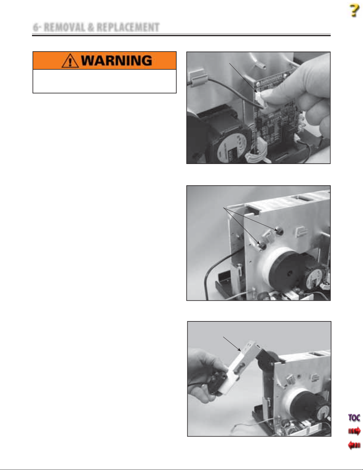
6 REMOVAL & REPLACEMENT
6.7 LOAD CELL ASSEMBLY REMOVAL & REPLACEMENT
Unplug the unit from the power source before
attempting removal or replacement procedures to
prevent electrical shock.
A. Part Numbers
Load Cell Assembly . . . . . . . . . . . . . . . . . . . .48009
B. Equipment Required
3/32 in Allen Wrench
•
4 mm Hex Key Socket and Ratchet
•
Calibrated Torque Wrench- 200 inch pound
•
or 2,500 Newton meter minimum capacity.
C. Removal of Load Cell Assembly
1. Remove Side Covers. Refer to 6.1 Side Cover
Removal & Replacement.
2. Remove the Top Cover. Refer to 6.2 Top and
Cord Guide Cover Removal & Replacement,
part C, steps 2-5.
3. Remove Rear Cover. Refer to 6.3 Rear Cover
Removal & Replacement.
4. Remove the Clamp Spring Assembly.
Refer to 6.8 Clamp Spring Assembly
Removal & Replacement.
5. Disconnect the Load Cell Harness from the
Motor Control Board. See Figure 6.21.
6. Using the 4 mm Hex Key Socket and
Ratchet, remove the two Load Cell
Mounting Screws and Flat Washers from
each side of the Chassis. See Figure 6.22.
7. Lift Load Cell Assembly out of Chassis. See
Figure 6.23.
LOAD CELL HARNESS
MOUNTING SCREWS
Tru-Trac and TX® Therapeutic Traction Unit
LOAD CELL HARNESS
FIGURE 6.21
2 EACH SIDE
FIGURE 6.22
35
LOAD CELL
ASSEMBLY
FIGURE 6.23
Page 38
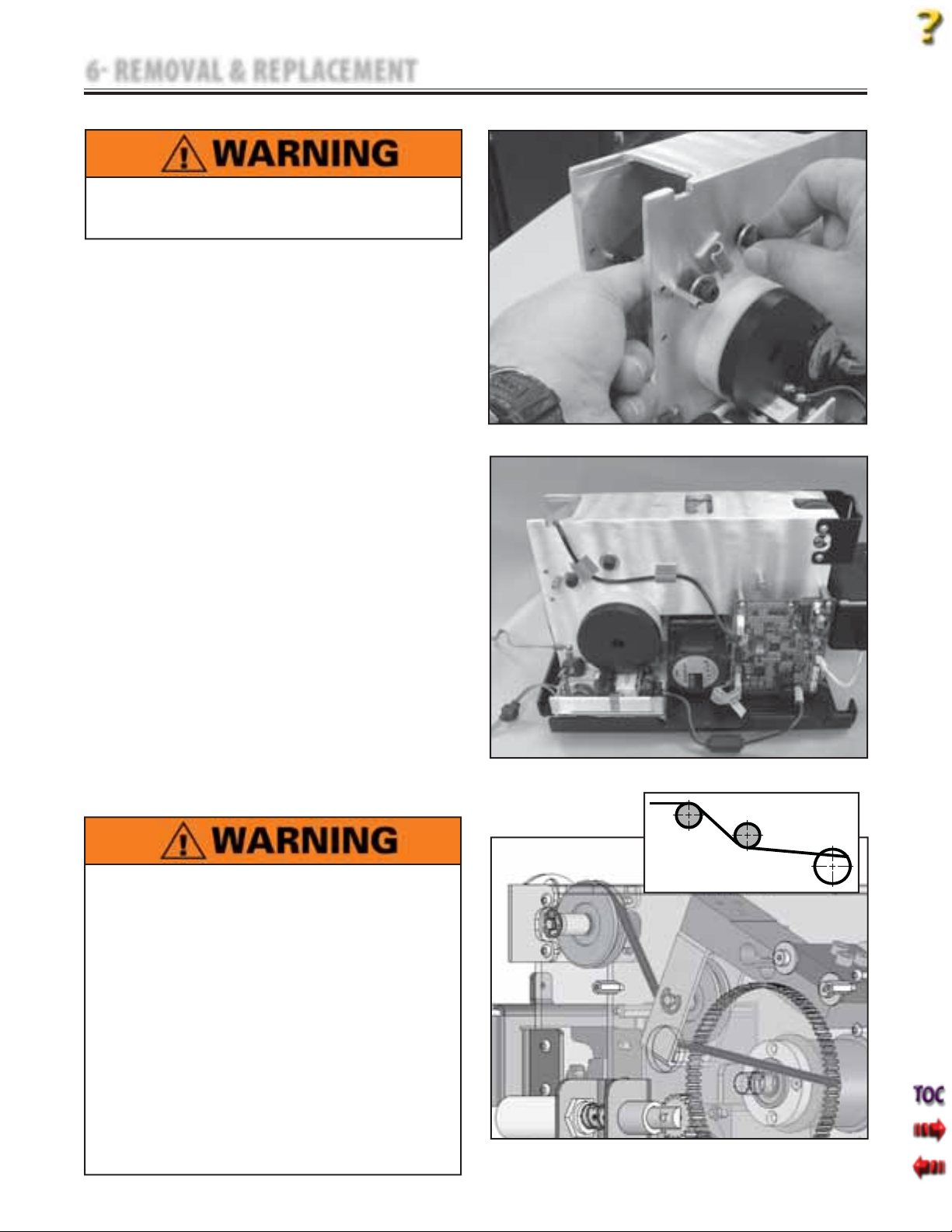
6 REMOVAL & REPLACEMENT
6.7 LOAD CELL ASSEMBLY REMOVAL & REPLACEMENT (continued)
Unplug the unit from the power source before
attempting removal or replacement procedures to
prevent electrical shock.
D. Replacement of Load Cell Assembly
1. Place Load Cell Assembly into Chassis and
hold in position while hand starting the
Load Cell Mounting Screws and Flat
Washers. See Figure 6.24.
2. Hand tighten the Load Cell Mounting
Screws.
3. Install the Clamp Spring Assembly.
Refer to 6.8 Clamp Spring Assembly
Removal & Replacement.
4. Use the Torque Wrench and 4 mm Hex
Key Socket to torque the Load Cell
Mounting Screws to 35 Nm (84 in lbs).
5. Route Load Cell Harness through Harness
Clips on the Chassis and connect to Motor
Control Board. See Figure 6.25.
6. Route Traction Cord through the Load Cell
Assembly Pulley and through the Chassis
Upper Guide Pulley. See Figure 6.26.
7. Install Rear Cover. Refer to 6.3 Rear Cover
Removal & Replacement.
8. Install Top Cover. Refer to 6.2 Top and Cord
Guide Cover Removal & Replacement.
9. Install Side Covers. Refer to 6.1 Side Cover
Removal & Replacement.
10. Perform complete Calibration and Burn In
of unit.
Tru-Trac and TX® Therapeutic Traction Unit
FIGURE 6.24
FIGURE 6.25
This removal and replacement procedure requires
that the following be performed after component or
assembly replacement to ensure proper alignment
and operation of the unit:
1. COMPLETE CALIBRATION OF UNIT
Refer to Section 7
AND
2. MINIMUM OF 2 HOUR BURN IN OF UNIT
AFTER SUCCESSFUL CALIBRATION
Refer to Section 7
Failure to perform either of these procedures after
a component or assembly replacement will void
warranty and may result in injury to patients and
severe equipment damage.
FIGURE 6.26
36
Page 39
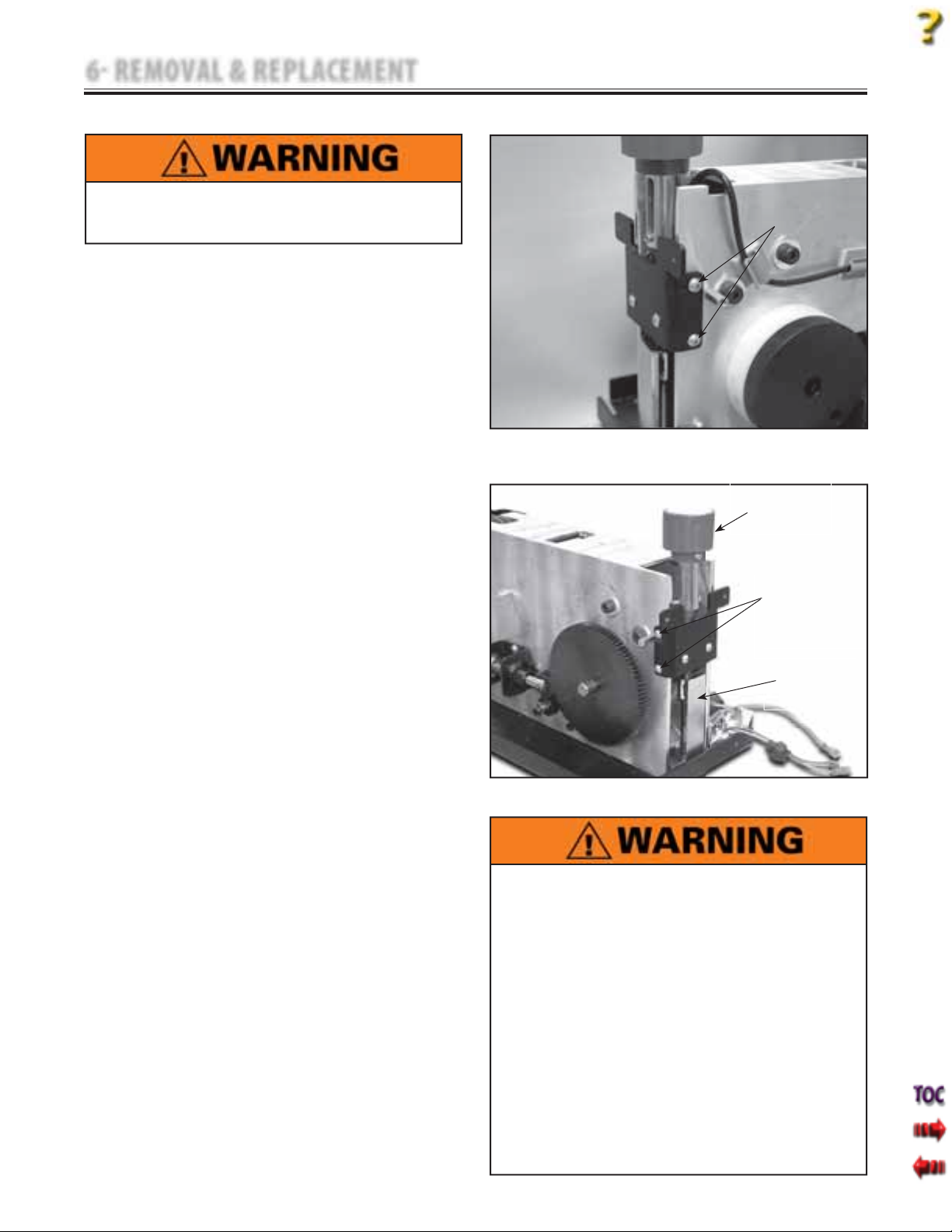
6 REMOVAL & REPLACEMENT
6.8 CLAMP SPRING ASSEMBLY REMOVAL & REPLACEMENT
Unplug the unit from the power source before
attempting removal or replacement procedures to
prevent electrical shock.
A. Part Numbers
Clamp Spring Assembly . . . . . . . . . . . . . . .48023
B. Equipment Required
3/32 in Allen Wrench
C. Clamp Spring Assembly Removal
1. Remove Side Covers. Refer to 6.1 Side Cover
Removal & Replacement.
2. Remove the Top Cover. Refer to 6.2 Top and
Cord Guide Cover Removal & Replacement,
part C, steps 2-5.
3. Remove Rear Cover. Refer to 6.3 Rear Cover
Removal & Replacement.
4. Remove the four Clamp Spring Assembly
Mounting Screws. See Figure 6.27.
5. Turn the Clamp Knob Counterclockwise
until it is completely disengaged from the
Clamp Plate. See Figure 6.28.
D. Clamp Spring Assembly Replacement
1. Position the Clamp Spring Assembly at the
Chassis and rotate Clamp Knob until the
threaded portion is fully engaged in the
Clamp Plate and the Clamp Spring
Assembly Mounting Bracket is aligned with
the respective mounting holes in the
Chassis. Secure with the four Clamp Spring
Assembly Mounting Screws.
2. Install Rear Cover. Refer to 6.3 Rear Cover
Removal & Replacement.
3. Install Top Cover. Refer to 6.2 Top and
Cord Guide Cover Removal & Replacement.
4. Install Side Covers. Refer to 6.1 Side Cover
Removal & Replacement.
5. Perform complete Calibration and Burn In
of unit.
This removal and replacement procedure requires
that the following be performed after component or
assembly replacement to ensure proper alignment
and operation of the unit:
2. MINIMUM OF 2 HOUR BURN IN OF UNIT
Tru-Trac and TX® Therapeutic Traction Unit
CLAMP SPRING
ASSEMBLY
SCREWS
2 EACH SIDE
FIGURE 6.27
CLAMP KNOB
CLAMP SPRING
ASSEMBLY
MOUNTING SCREWS
2 EACH SIDE
CLAMP PLATE
FIGURE 6.28
1. COMPLETE CALIBRATION OF UNIT
Refer to Section 7
AND
AFTER SUCCESSFUL CALIBRATION
Refer to Section 7
Failure to perform either of these procedures after
a component or assembly replacement will void
warranty and may result in injury to patients and
severe equipment damage.
37
Page 40
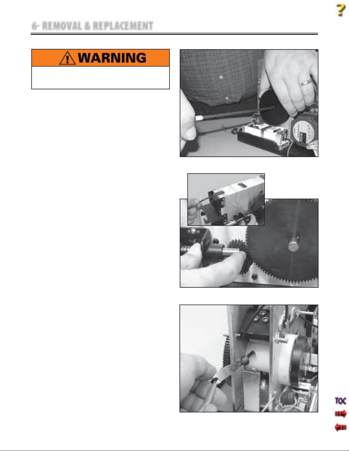
6 REMOVAL & REPLACEMENT
6.9 TRACTION CORD REMOVAL & REPLACEMENT
Unplug the unit from the power source before
attempting removal or replacement procedures to
prevent electrical shock.
A. Part Numbers
Traction Cord . . . . . . . . . . . . . . . . . . . . . . . . . .48031
B. Equipment Required
3/32 in Allen Wrench
•
5/32 in Allen Wrench
•
Needle Nose Pliers
•
Tape Measure
•
C. Clamp Spring Assembly Removal
1. Remove Side Covers. Refer to 6.1 Side Cover
Removal & Replacement.
2. Remove the Top Cover. Refer to 6.2 Top and
Cord Guide Cover Removal & Replacement,
part C, steps 2-5.
3. Remove Rear Cover. Refer to 6.3 Rear Cover
Removal & Replacement.
4. Remove the Clamp Spring Assembly. Refer
to 6.8 Clamp Spring Removal and
Replacement.
5. While holding the Cord Tension Spring
Housing in position with one hand, loosen
the retaining screw with the other hand.
See Figure 6.29.
6. Gradually release the spring tension by
allowing the Spring Housing to slowly
rotate in the hand. Leave the Housing
Retaining Screw loose.
7. Manually release the Solenoid from the
Large Driven Gear and simultaneously
pull the Traction Cord through the unit
front until the Traction Cord stops. See
Figure 6.30.
NOTE:
Make certain the Traction Cord Knot is facing the rear
of the unit.
8. Release the Solenoid, making certain it fully
engages the teeth of the Large Driven Gear.
NOTE:
It may be necessary to slightly jog the Large Driven
Gear to facilitate tooth engagement.
9. Remove the Traction Cord Knuckle. Refer to
page 41, step 11. Using the Needle Nose
Pliers, pull the Traction Cord Knot from the
Traction Cord Spool and completely pull the
Traction Cord out of unit. See Figure 6.31.
Tru-Trac and TX® Therapeutic Traction Unit
FIGURE 6.29
FIGURE 6.30
FIGURE 6.31
38
Page 41
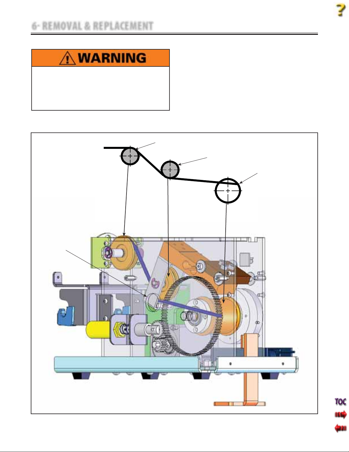
6 REMOVAL & REPLACEMENT
6.9 TRACTION CORD REMOVAL & REPLACEMENT (continued)
D. Traction Cord Replacement
1. Route Traction Cord through the Traction
Unplug the unit from the power source before
•
attempting removal or replacement procedures to
prevent electrical shock.
It is not recommend tying a new knot in a cord that
•
has frayed or failed in use or is worn in an area from
constant use. The cord must be replaced.
TOP GUIDE PULLEY
Cord Spool, Load Cell Pulley, and Top Guide
Pulley. See Figure 6.32
NOTE:
The left side of the Chassis incorporates a Window to
facilitate proper routing of the Traction Cord.
Tru-Trac and TX® Therapeutic Traction Unit
LOAD CELL PULLEY
TRACTION CORD SPOOL
TRACTION CORD
ROUTING WINDOW
FIGURE 6.32
39
Page 42
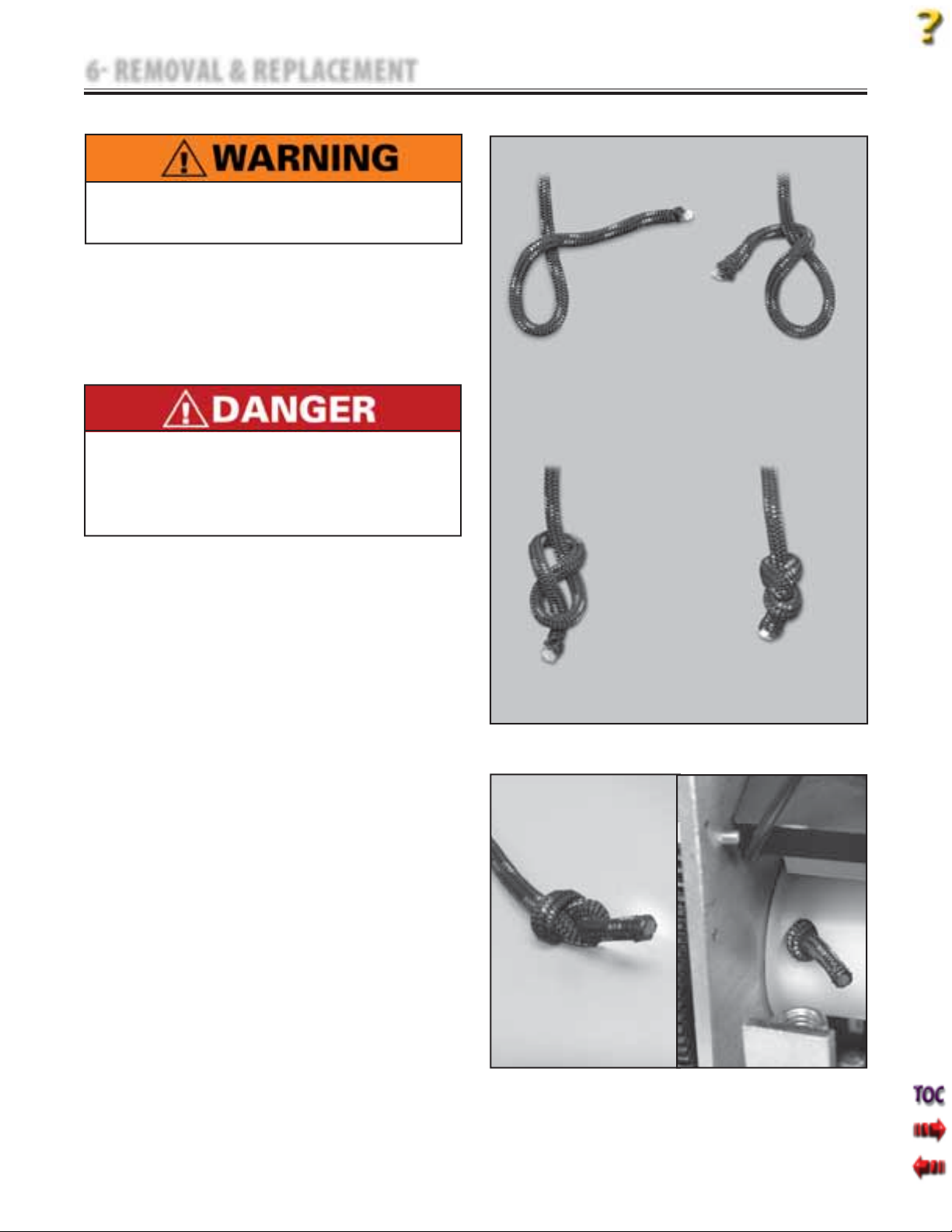
6 REMOVAL & REPLACEMENT
6.9 TRACTION CORD REMOVAL & REPLACEMENT (continued)
Unplug the unit from the power source before
attempting removal or replacement procedures to
prevent electrical shock.
2. Pull enough of the Traction Cord through
the Traction Cord Spool to allow the knot
to be tied.
3. Tie a Figure Eight (Flemish, Savoy) Knot
in the end of the Cord passing through the
Traction Cord Spool. See Figure 6.33.
1
Do not use any other knot styles in the Cord other
than those specified in this manual. Use of other knot
styles could cause Cord to completely disengage
from the system causing serious injury to patient
and personnel.
Tru-Trac and TX® Therapeutic Traction Unit
2
4. Trim any fraying from the Traction Cord
leaving 19 mm (0.75 in) of Cord outside the
Figure Eight (Flemish, Savoy) Knot.
5. Singe the Cord end until the outer jacket
and inner core of the Traction Cord melt
together. See Figure 6.34A.
6. Pull other end of Traction Cord until the
Figure Eight (Flemish, Savoy) Knot is
completely seated within the Traction Cord
Spool. See Figure 6.34B.
NOTE:
It may be necessary to use a long, thin tool such as a
Flat Blade Screwdriver to properly tuck the Figure Eight
(Flemish, Savoy) Knot into the Traction Cord Spool.
3
4
FIGURE 6.33
40
FIGURE 6.34A
FIGURE 6.34B
Page 43
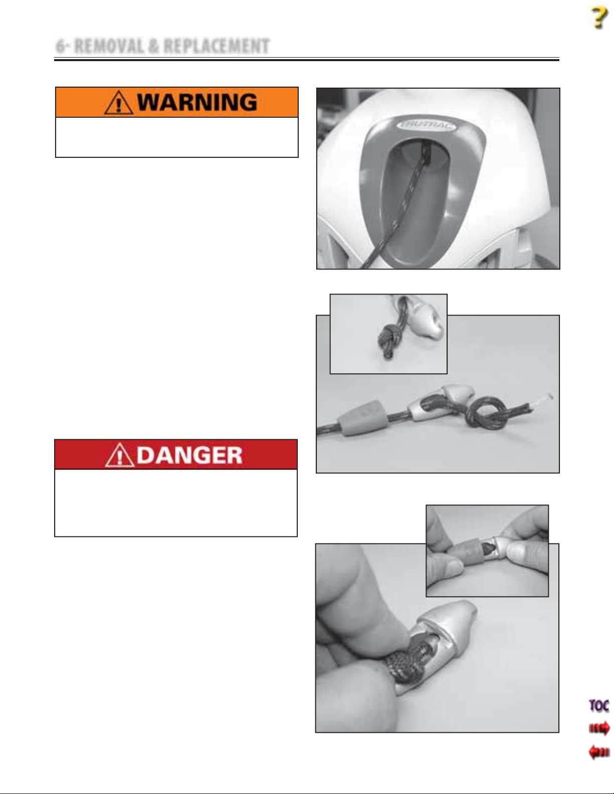
6 REMOVAL & REPLACEMENT
6.9 TRACTION CORD REMOVAL & REPLACEMENT (continued)
Unplug the unit from the power source before
attempting removal or replacement procedures to
prevent electrical shock.
7. Route Traction Cord through the Front
Cord Guide Support.
8. Route Traction Cord through the Top
Cover and place the Top Cover in Position
on the Chassis. See Figure 6.35. Do not
secure Top Cover at this time.
9. Inspect Traction Cord Knuckle for damage
and wear. Replace if damaged or worn.
10. Route Traction Cord through Traction
Cord Knuckle Cover and Cord Knuckle. Tie
an Overhand or Half Knot in the end of
the Traction Cord leaving 25.5 mm
(1.00 in) of Traction Cord outside the
knot. See Figure 6.36.
11. Trim any fraying from the end of the
Traction Cord and singe the Cord end
until the outer jacket and inner core of
the Traction Cord melt together. Make
certain at least 19 mm (0.750 in) of
Traction Cord still remains outside the
knot. See Figure 6.36 inset.
Tru-Trac and TX® Therapeutic Traction Unit
FIGURE 6.35
Do not use any other knot styles in the Cord other
than those specified in this manual. Use of other knot
styles could cause Cord to completely disengage
from the system and may cause serious injury to
patient and personnel.
12. Secure the knot inside the Traction Cord
Knuckle ensuring the loose end enters
the Bore inside the Traction Cord
Knuckle. See Figure 6.37. Slide Traction
Cord Knuckle Cover into position over the
knot. See Figure 6.37 inset.
NOTE:
It may be necessary to use a long, thin tool such as a
Flat Blade Screwdriver to properly tuck the loose end
of the Traction Cord into the Bore of the Traction Cord
Knuckle.
FIGURE 6.36
FIGURE 6.37
41
Page 44
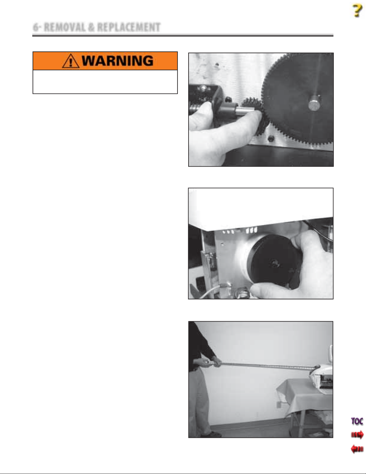
6 REMOVAL & REPLACEMENT
6.9 TRACTION CORD REMOVAL & REPLACEMENT (continued)
Unplug the unit from the power source before
attempting removal or replacement procedures to
prevent electrical shock.
NOTE:
If adjusting Spring Tension only and not replacing the
Traction Cord, it will be necessary to remove the Side
Covers and have available the Tools required in 6.9, B.
13. Manually release the Solenoid and
simultaneously fully extend the Traction
Cord. Release Solenoid and make certain
the Solenoid Gear fully engages the
Large Driven Gear. See Figure 6.38.
14. With the Cord fully extended, rotate the
Cord Spring Housing clockwise until
the Cord Spring is completely wound,
then rotate counterclockwise 1/4 to 1/2
turn. Hold the Cord Spring Housing in
position and tighten the Retaining Screw
using the 5/32 in Allen Wrench. See
Figure 6.39.
NOTE:
Overtightening of the Cord Spring Housing Retaining
Screw will break the housing and cause the spring to
lose tension.
15. While holding on to the Traction Cord,
manually release the Solenoid and allow
the Traction Cord to retract.
16. Manually release the Solenoid and
simultaneously fully extend the Traction
Cord. Release Solenoid and make certain
it fully engages the Large Driven Gear.
17. Using Tape Measure, measure the length
of the Cord from the Cord Guide Cover to
the end of the Harness Clip. See
Figure 6.40. Measurement should be
96.5 cm to 106.5 cm (38 in to 42 in).
a) If measurement is less than 96.5 cm
(38 in), Spring Tension is too tight.
Loosen the Spring Housing Retaining
Screw and allow the housing to release
no more than 1/2 revolution of tension.
Tighten Spring Housing Retaining
Screw and repeat steps 15 and 16.
b) If measurement is more than 106.5 cm
(42 in), increase Traction Cord Spring
Tension by no more than 1/2
revolution.
18. Repeat step 17 a or b until Cord
dimension is correct.
Tru-Trac and TX® Therapeutic Traction Unit
FIGURE 6.38
FIGURE 6.39
FIGURE 6.40
42
Page 45
6 REMOVAL & REPLACEMENT
6.9 TRACTION CORD REMOVAL & REPLACEMENT (continued)
Unplug the unit from the power source before
attempting removal or replacement procedures to
prevent electrical shock.
19. Install Clamp Spring Assembly. Refer to
6.8 Clamp Spring Assembly Removal &
Replacement.
20. Install Rear Cover. Refer to 6.3 Rear Cover
Removal & Replacement.
21. Install Top Cover. Refer to 6.2 Top and
Cord Guide Cover Removal &
Replacement.
22. Install Side Covers. Refer to 6.1 Side Cover
Removal & Replacement.
23. Perform complete Calibration and Burn In
of unit.
Tru-Trac and TX® Therapeutic Traction Unit
This removal and replacement procedure requires
that the following be performed after component or
assembly replacement to ensure proper alignment
and operation of the unit:
1. COMPLETE CALIBRATION OF UNIT
Refer to Section 7
AND
2. MINIMUM OF 2 HOUR BURN IN OF UNIT
AFTER SUCCESSFUL CALIBRATION
Refer to Section 7
Failure to perform either of these procedures after
a component or assembly replacement will void
warranty and may result in injury to patients and
severe equipment damage.
43
Page 46
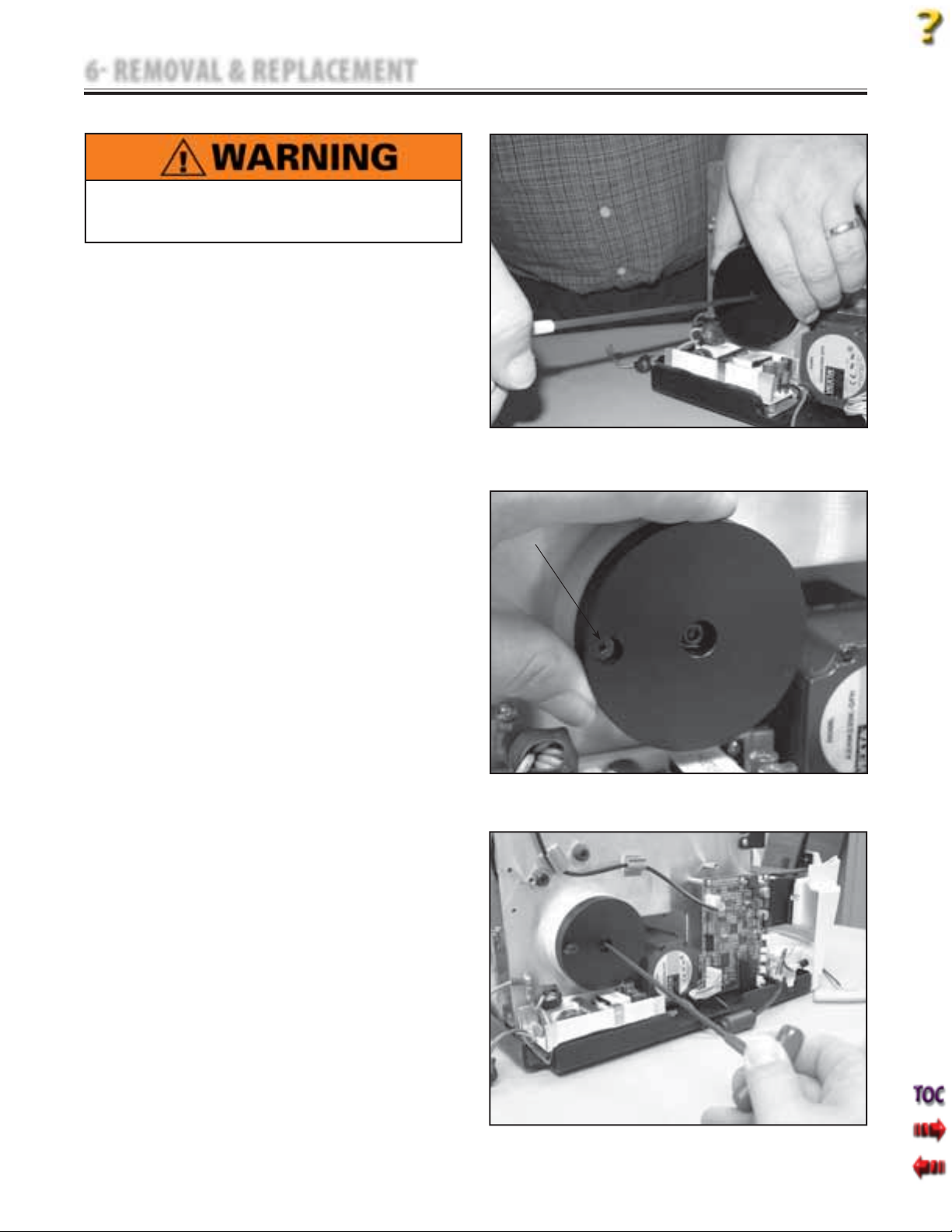
6 REMOVAL & REPLACEMENT
6.10 CORD TENSION SPRING REMOVAL & REPLACEMENT
Unplug the unit from the power source before
attempting removal or replacement procedures to
prevent electrical shock.
A. Part Numbers
Cord Tension Spring . . . . . . . . . . . . . . . . . . .80653
B. Equipment Required
3/32 in Allen Wrench
•
5/32 in Allen Wrench
•
C. Cord Tension Spring Removal
1. Remove Side Covers. Refer to 6.1 Side Cover
Removal & Replacement.
2. Remove the Top Cover. Refer to 6.2 Top and
Cord Guide Cover Removal & Replacement,
part C, steps 2-5.
3. While holding the Cord Tension Spring
Housing with one hand. Loosen the
retaining screw with the other hand using
the 5/32 in Allen Wrench. See Figure 6.41.
4. Gradually allow the Spring Housing to
rotate in the hand releasing spring tension.
5. Rotate the Cord Tension Spring Housing
until the hole in the face aligns with the
Spring Mounting Screw. Remove screw with
the 3/32 in Allen Wrench. See Figure 6.42.
6. Remove the Cord Tension Spring Housing
Mounting Screw. See Figure 6.43.
7. Remove Cord Tension Spring and Housing
from unit.
SPRING
MOUNTING
SCREW
Tru-Trac and TX® Therapeutic Traction Unit
FIGURE 6.41
FIGURE 6.42
44
FIGURE 6.43
Page 47
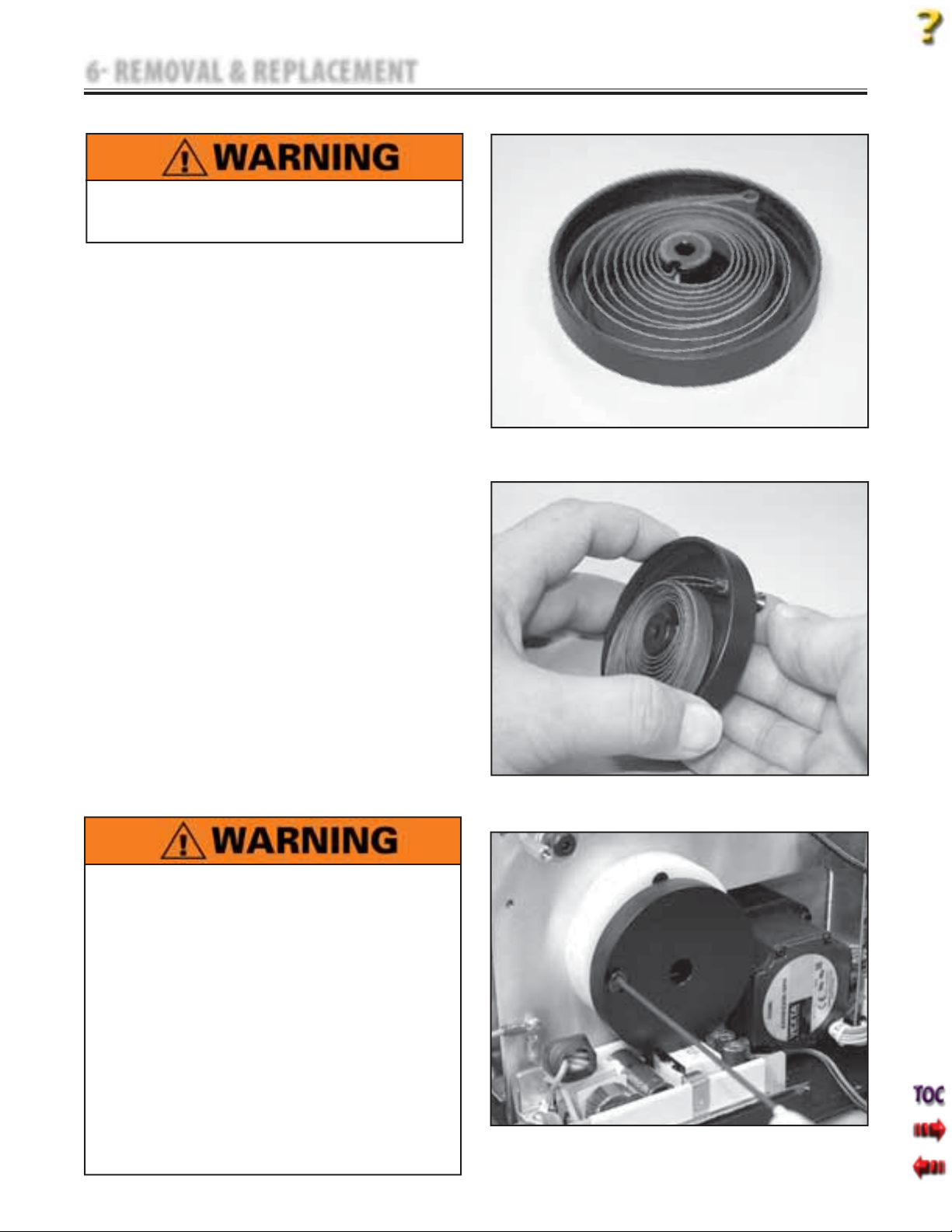
6 REMOVAL & REPLACEMENT
6.10 CORD TENSION SPRING REMOVAL & REPLACEMENT (continued)
Unplug the unit from the power source before
attempting removal or replacement procedures to
prevent electrical shock.
D. Cord Tension Spring Replacement
1. Position new Cord Tension Spring in
Housing as shown in Figure 6.44.
2. Place Spring Mounting Screw through hole
in face of the Housing and through the
Cord Tension Spring Mounting Loop. Leave
the head of the Spring Mounting Screw
protruding through the Housing. See
Figure 6.45
3. Position the Spring and Housing assembly
in the mounting position on the Chassis.
Start the Spring Mounting Screw using the
3/32 in Allen Wrench. Tighten Mounting
Screw until Cord Tension Spring Mounting
Loop is secure then, back the screw out one
complete revolution. See Figure 6.46.
4. Position the Spring and Housing so that the
Housing Mounting Screw can be started.
Start screw with the 5/32 in Allen Wrench.
5. Adjust Spring Tension. Refer to page 42.
6. Install Top Cover. Refer to 6.2 Top and
Cord Guide Cover Removal &
Replacement.
7. Install Side Covers. Refer to 6.1 Side Cover
Removal & Replacement.
8. Perform complete Calibration and Burn In
of unit.
Tru-Trac and TX® Therapeutic Traction Unit
FIGURE 6.44
FIGURE 6.45
This removal and replacement procedure requires
that the following be performed after component or
assembly replacement to ensure proper alignment
and operation of the unit:
1. COMPLETE CALIBRATION OF UNIT
Refer to Section 7
AND
2. MINIMUM OF 2 HOUR BURN IN OF UNIT
AFTER SUCCESSFUL CALIBRATION
Refer to Section 7
Failure to perform either of these procedures after
a component or assembly replacement will void
warranty and may result in injury to patients and
severe equipment damage.
FIGURE 6.46
45
Page 48
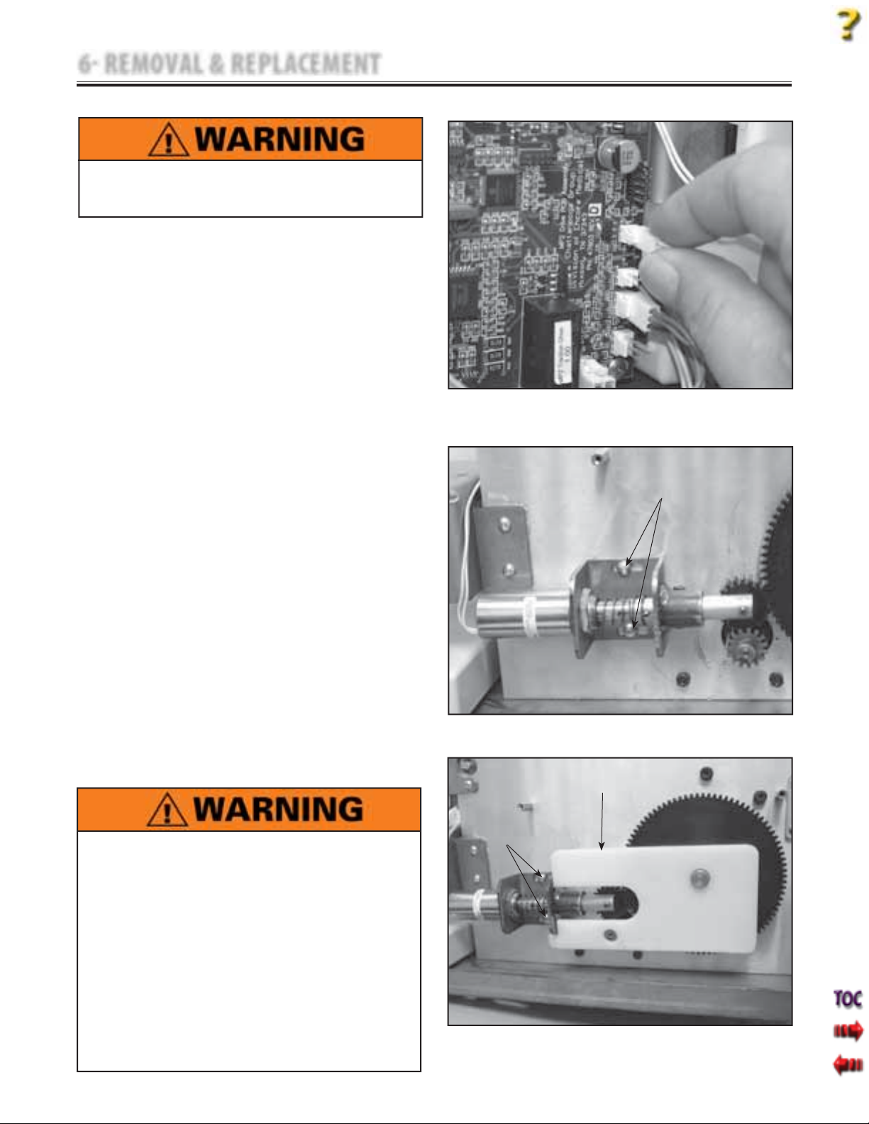
6 REMOVAL & REPLACEMENT
6.11 SOLENOID ASSEMBLY REMOVAL & REPLACEMENT
Unplug the unit from the power source before
attempting removal or replacement procedures to
prevent electrical shock.
A. Part Numbers
Solenoid Assembly . . . . . . . . . . . . . . . . . . . . 48014
B. Equipment Required
•
9/64 in Allen Wrench
•
Solenoid Assembly Mounting Jig(P/N 48139)
C. Solenoid Assembly Removal
1. Remove Side Covers. Refer to 6.1 Side Cover
Removal & Replacement.
2. Make certain the Cord is fully retracted. If
necessary, manually retract. Refer to
Figure 5.12.
3. Disconnect the Solenoid Assembly Harness
from Motor Control Board. See Figure 6.47.
4. Using the 9/64 in Allen Wrench, remove the
two Solenoid Assembly Mounting Screws.
See Figure 6.48.
D. Solenoid Assembly Replacement
1. Position the Solenoid Assembly Mounting
Jig onto the Shafts of the Large Driven Gear
and the Motor Gear. See Figure 6.49.
2. Position the Solenoid Assembly so gears are
fully seated and the front and bottom of the
Bracket are against the Solenoid Assembly
Mounting Jig. Secure with screws. See
Figure 6.49.
3. Connect Solenoid Assembly Harness to
Motor Control Board. See Figure 6.47.
4. Install Side Covers. Refer to 6.1 Side Cover
Removal & Replacement.
5. Perform complete Calibration and Burn In
of unit.
Tru-Trac and TX® Therapeutic Traction Unit
FIGURE 6.47
SOLENOID
MOUNTING
SCREWS
FIGURE 6.48
SOLENOID ASSEMBLY
MOUNTING JIG P/N 48139
This removal and replacement procedure requires
that the following be performed after component or
assembly replacement to ensure proper alignment
and operation of the unit:
1. COMPLETE CALIBRATION OF UNIT
Refer to Section 7
AND
2. MINIMUM OF 2 HOUR BURN IN OF UNIT AFTER
SUCCESSFUL CALIBRATION
Refer to Section 7
Failure to perform either of these procedures after
a component or assembly replacement will void
warranty and may result in injury to patients and
severe equipment damage.
SOLENOID
MOUNTING
SCREWS
FIGURE 6.49
46
Page 49
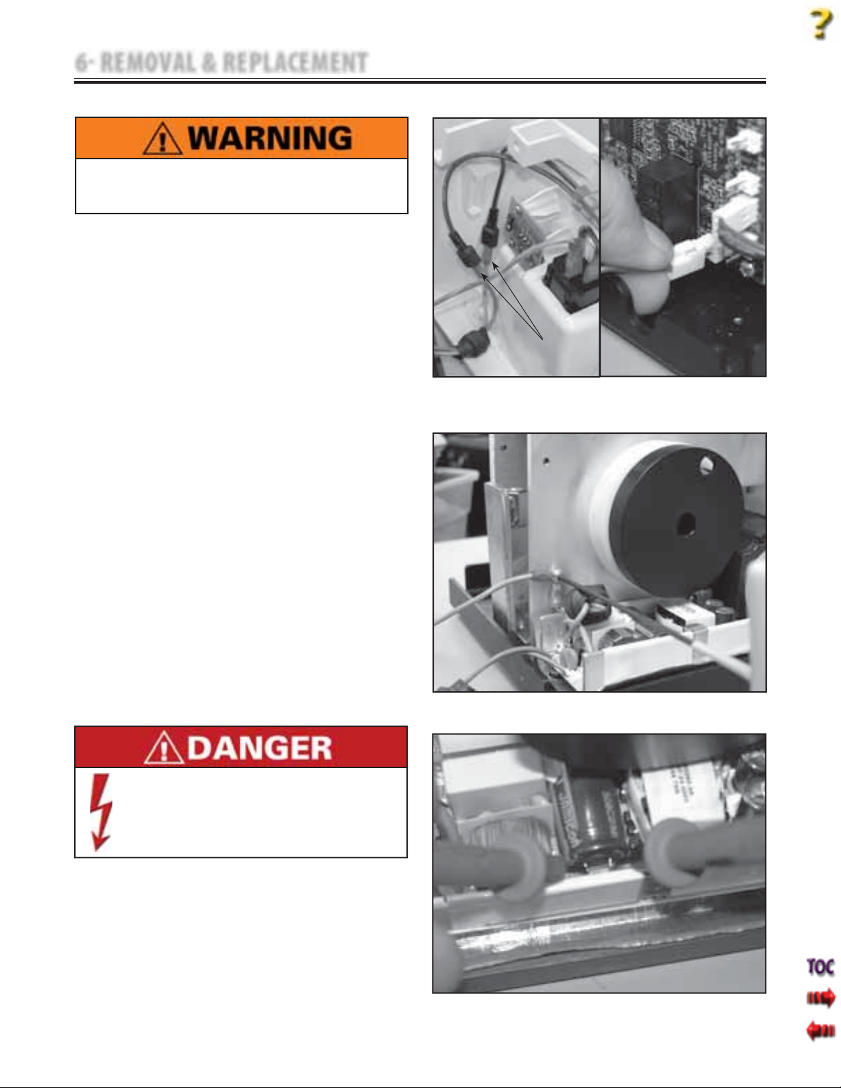
6 REMOVAL & REPLACEMENT
6.12 POWER SUPPLY REMOVAL & REPLACEMENT
Unplug the unit from the power source before
attempting removal or replacement procedures to
prevent electrical shock.
A. Part Numbers
Power Supply . . . . . . . . . . . . . . . . . . . . . . . . . .27265
Power Supply Shield . . . . . . . . . . . . . . . . . . 27592
B. Equipment Required
3/32 in Allen Wrench
•
#2 Phillips Screwdriver
•
Digital Multimeter (Set to VDC)
•
C. Power Supply Removal
1. Remove Side Covers. Refer to 6.1 Side Cover
Removal & Replacement.
2. Remove the Top Cover. Refer to 6.2 Top and
Cord Guide Cover Removal & Replacement.
3. Remove Rear Cover. Refer to 6.3 Rear Cover
Removal & Replacement.
4. Disconnect the Power Supply Input
Harnesses from the Mains Connector. See
Figure 6.50A.
5. Disconnect Power Supply Output
Harness from the Motor Control Board. See
Figure 6.50B.
6. Using the 3/32 in Allen Wrench, remove the
Ground Harnesses from the Chassis. See
Figure 6.51.
7. Using the Multimeter set to VDC discharge
the Power Supply Capacitor at C4. See
Figure 6.52.
POWER SUPPLY
INPUT HARNESSES
FIGURE 6.50A
Tru-Trac and TX® Therapeutic Traction Unit
FIGURE 6.50B
FIGURE 6.51
Power Supplies retain High Voltage!
•
Discharge the C4 Capacitor prior to
•
complete removal of the Power Supply.
8. Using the #2 Phillips Screwdriver, remove
the four Power Supply Mounting Screws.
9. Grasp the sides of the Power Supply and
carefully remove from the chassis.
FIGURE 6.52
47
Page 50
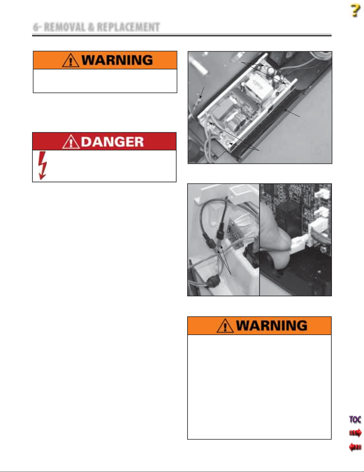
6 REMOVAL & REPLACEMENT
6.12 POWER SUPPLY REMOVAL & REPLACEMENT (continued)
POWER SUPPLY
MOUNTING SCREWS
Tru-Trac and TX® Therapeutic Traction Unit
Unplug the unit from the power source before
attempting removal or replacement procedures to
prevent electrical shock.
D. Power Supply Replacement
1. Prior to handling new Power Supply,
discharge the Capacitor at C4. Refer to
page 47.
Power Supplies retain High Voltage!
•
Discharge the C4 Capacitor prior to
•
handling of the new Power Supply.
2. Make certain the Shield is in place with
the nonconductive (black) side toward
the Power Supply. Position the Power
Supply on the Chassis. Secure with the
four Power Supply Mounting Screws. See
Figure 6.53.
3. Using the 3/32 in Allen Wrench and Ground
Harness Mounting Screw, secure the
Ground Harnesses from the Power Supply
and the Mains Connector to the Chassis.
See Figure 6.53.
4. Connect the Power Supply Input Harnesses
to the Mains Connector Harnesses. See
Figure 6.54A.
5. Connect the Power Supply Output
Harness to the Motor Control Board. See
Figure 6.54B.
6. Install Rear Cover. Refer to 6.3 Rear Cover
Removal & Replacement.
7. Install Top Cover. Refer to 6.2 Top and
Cord Guide Cover Removal &
Replacement.
8. Install Side Covers. Refer to 6.1 Side Cover
Removal & Replacement.
9. Perform complete Calibration and Burn In
of unit.
GROUND
HARNESSES
SHIELD
BLACK SIDE TOWARD
POWER SUPPLY
POWER SUPPLY
MOUNTING SCREWS
FIGURE 6.53
POWER SUPPLY
INPUT HARNESSES
FIGURE 6.54A
FIGURE 6.54B
This removal and replacement procedure requires
that the following be performed after component or
assembly replacement to ensure proper alignment
and operation of the unit:
1. COMPLETE CALIBRATION OF UNIT
Refer to Section 7
AND
2. MINIMUM OF 2 HOUR BURN IN OF UNIT
AFTER SUCCESSFUL CALIBRATION
Refer to Section 7
Failure to perform either of these procedures after
a component or assembly replacement will void
warranty and may result in injury to patients and
severe equipment damage.
48
Page 51
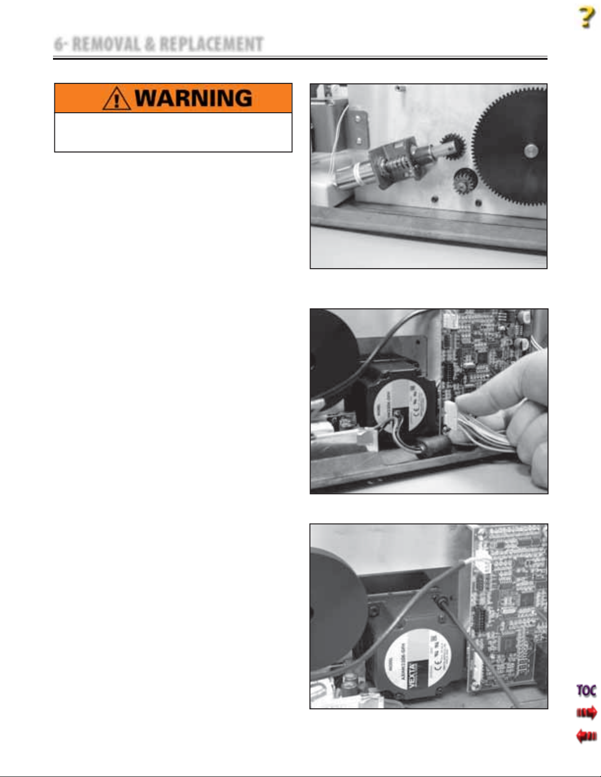
6 REMOVAL & REPLACEMENT
6.13 MOTOR ASSEMBLY REMOVAL & REPLACEMENT
Unplug the unit from the power source before
attempting removal or replacement procedures to
prevent electrical shock.
A. Part Numbers
Motor Assembly . . . . . . . . . . . . . . . . . . . . . . .48019
B. Equipment Required
3/32 in Allen Wrench
•
3 mm Allen Wrench
•
7 mm Box End Wrench
•
Solenoid Assembly Mounting Jig
•
C. Motor Assembly Removal
1. Remove Side Covers. Refer to 6.1 Side Cover
Removal & Replacement.
2. Make certain Traction Cord is completely
retracted. If necessary, manually release
Solenoid to retract Cord.
3. Loosen the Solenoid Mounting Screws
enough to rotate Solenoid Gear up and off
of the Motor Gear. See Figure 6.55.
4. Disconnect the Motor Harness from the
Motor Control Board. See Figure 6.56.
5. Using the 3 mm Allen Wrench and 7 mm
Boxed End Wrench, remove the four Motor
Assembly Mounting Screws. See Figure 6.57.
6. Remove Motor Assembly from Chassis.
NOTE:
It may be necessary to remove the Motor Control
Board. Refer to 6.5 Motor Control Board Removal &
Replacement.
Tru-Trac and TX® Therapeutic Traction Unit
FIGURE 6.55
FIGURE 6.56
49
FIGURE 6.57
Page 52
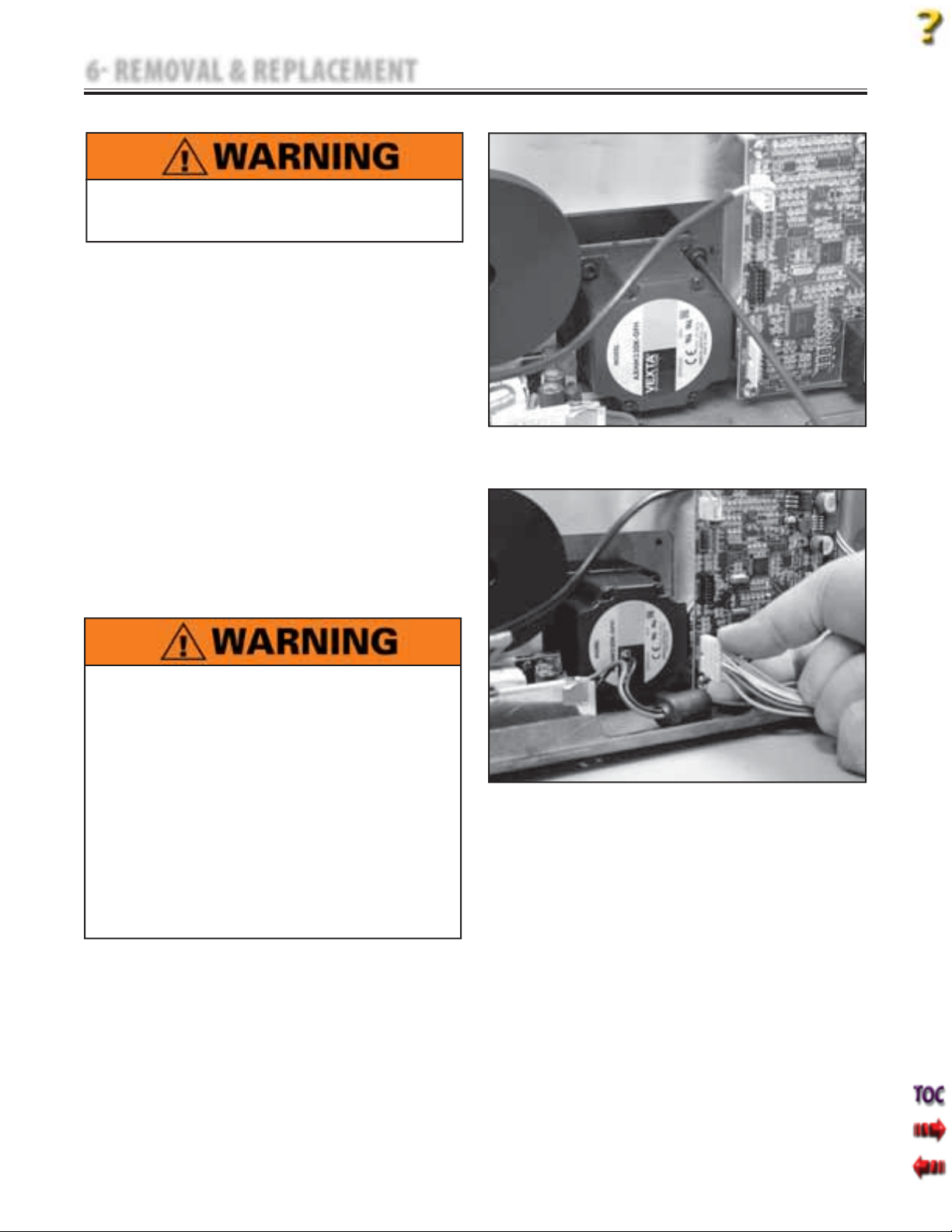
6 REMOVAL & REPLACEMENT
6.13 MOTOR ASSEMBLY REMOVAL & REPLACEMENT (continued)
Unplug the unit from the power source before
attempting removal or replacement procedures to
prevent electrical shock.
D. Motor Assembly Replacement
1. Position new Motor Assembly into Chassis
and secure with the four Motor Assembly
Screws, Lock washers, and Nuts. See
Figure 6.58.
2. Position and adjust the Solenoid. Refer to
6.11 Solenoid Assembly Removal &
Replacement.
NOTE:
If Motor Control Board was removed, re-install before
proceeding to step 3 below.
3. Connect the Motor Assembly Harness to
the Motor Control Board. See Figure 6.59.
4. Install Side Covers. Refer to 6.1 Side Cover
Removal & Replacement.
5. Perform complete Calibration and Burn In
of unit.
Tru-Trac and TX® Therapeutic Traction Unit
FIGURE 6.58
This removal and replacement procedure requires
that the following be performed after component or
assembly replacement to ensure proper alignment
and operation of the unit:
1. COMPLETE CALIBRATION OF UNIT
Refer to Section 7
AND
2. MINIMUM OF 2 HOUR BURN IN OF UNIT
AFTER SUCCESSFUL CALIBRATION
Refer to Section 7
Failure to perform either of these procedures after
a component or assembly replacement will void
warranty and may result in injury to patients and
severe equipment damage.
FIGURE 6.59
50
Page 53
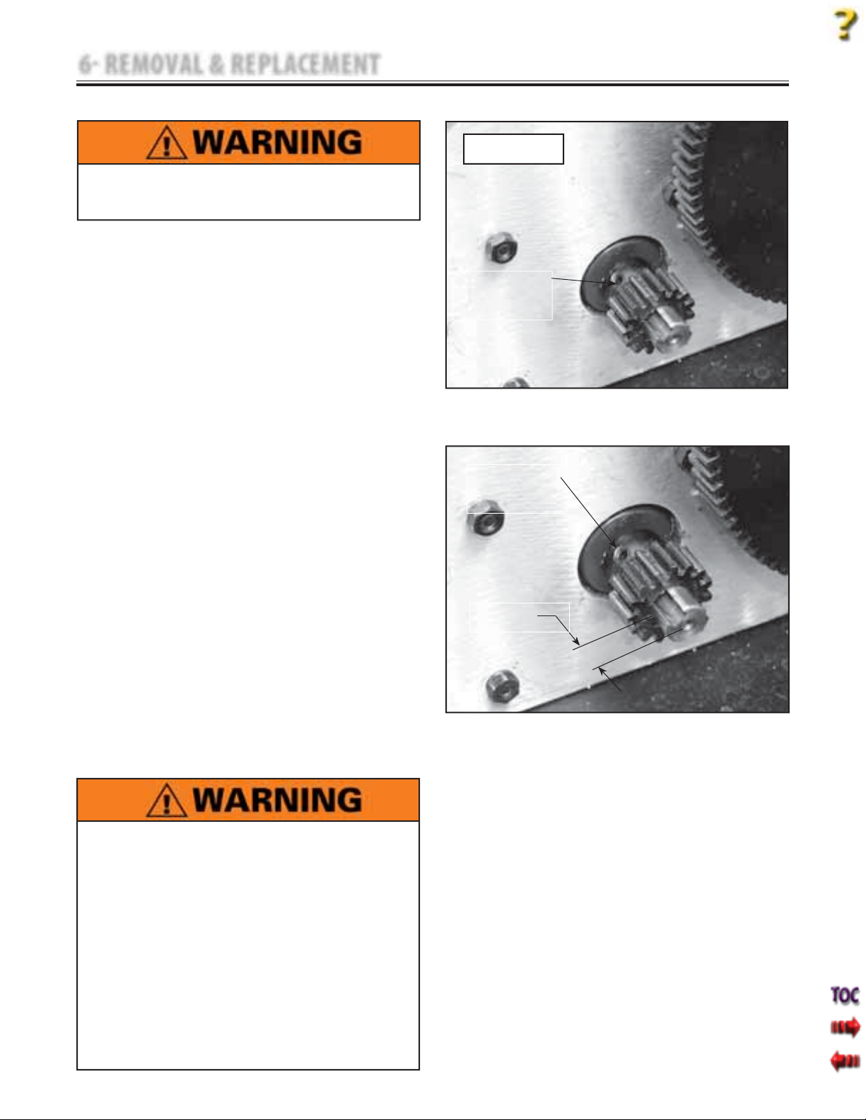
6 REMOVAL & REPLACEMENT
6.14 MOTOR DRIVE GEAR REMOVAL & REPLACEMENT
Unplug the unit from the power source before
attempting removal or replacement procedures to
prevent electrical shock.
A. Part Numbers
Motor Drive Gear . . . . . . . . . . . . . . . . . . . . . .48024
B. Equipment Required
3/32 in Allen Wrench
•
Solenoid Assembly Mounting Jig
•
Tape Measure
•
C. Motor Drive Gear Removal
1. Remove Side Covers. Refer to 6.1 Side Cover
Removal & Replacement.
2. Make certain Traction Cord is completely
retracted. If necessary, manually release
Solenoid to retract Cord.
3. Rotate Motor until Drive Gear Set Screw is
accessible. See Figure 6.60.
4. Using the 3/32 in Allen Wrench, loosen the
Drive Gear Set Screw and pull the Drive
Gear from Motor Shaft.
D. Motor Drive Gear Replacement
1. Install new Motor Drive Gear onto Motor
Shaft. Align Set Screw with the Key Slot in
the Motor Shaft. See Figure 6.61.
2. Adjust the Gear position until the face of
the gear is 9.5 mm (3/8 in) from the face of
the shaft. See Figure 6.61.
3. Tighten the Set Screw with the 3/32 in Allen
Wrench.
4. Install Side Covers. Refer to 6.1 Side Cover
Removal & Replacement.
Tru-Trac and TX® Therapeutic Traction Unit
SOLENOID REMOVED
FOR CLARITY
LOOSEN SET SCREW
FIGURE 6.60
TIGHTEN SET SCREW
9.5 MM
3/8"
FIGURE 6.61
This removal and replacement procedure requires
that the following be performed after component or
assembly replacement to ensure proper alignment
and operation of the unit:
1. COMPLETE CALIBRATION OF UNIT
Refer to Section 7
AND
2. MINIMUM OF 2 HOUR BURN IN OF UNIT
AFTER SUCCESSFUL CALIBRATION
Refer to Section 7
Failure to perform either of these procedures after
a component or assembly replacement will void
warranty and may result in injury to patients and
severe equipment damage.
51
Page 54
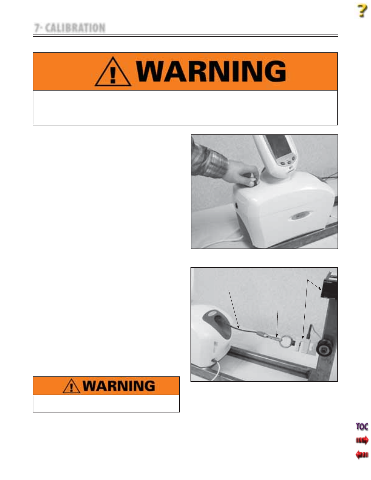
7 CALIBRATION
Tru-Trac and TX® Therapeutic Traction Unit
7.1 UNIT CALIBRATION
Certain removal and replacement procedures require that complete Unit Calibration and Burn In be performed
prior to placing the unit back into service.
Failure to perform either of these procedures after certain component or assembly replacement will void
warranty and may result in injury to patients and severe equipment damage.
A. General Information
1. The Calibration and Burn-In Procedures in
this section must be performed annually
and when field service requires removal and
replacement of certain components.
2. The Calibration Procedure requires use of
US lb Weight Measurements. The software
is fixed and will not perform conversions of
Metric Weight Measurements for this critical
procedure. Therefore, when constructing
and equipping the Calibration Fixture, it is
required that the Electronic Load Cell
Components be capable of expressing
US lbs.
3. The fabrication of a Calibration Fixture is
required for these units.
B. Equipment Required
FIGURE 7.1
Calibration Fixture with calibrated Strain Meter
C. Unit Calibration Procedure
1. Place unit on Calibration Fixture and secure
in position by tightening the unit Lock
Knob. See Figure 7.1.
SLACK IN
CORD
ACCESSORY CLIP TO
LOAD CELL
STRAIN METER
2. Connect unit to an approved power source.
3. Turn unit On.
4. Release Traction Cord and connect
Accessory Clip to the Strain Meter. Leave
slack in Cord. See Figure 7.2.
5. Zero Strain Meter LCD.
When performing Unit Calibration Procedure, the
Calibration Fixture Load Cell must be set to US lbs.
FIGURE 7.2
52
Page 55
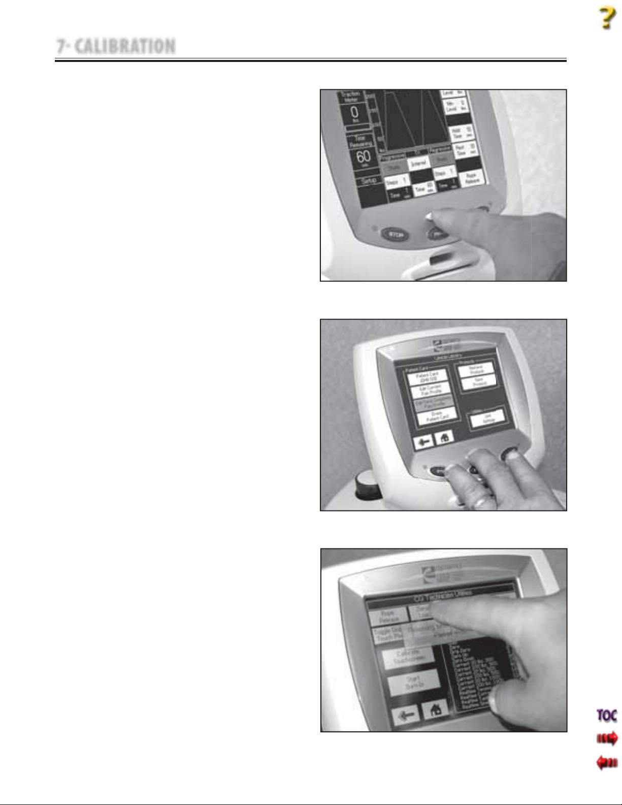
7 CALIBRATION
7.1 UNIT CALIBRATION (continued)
6. Press the Clinical Resources button. See
Figure 7.3.
Tru-Trac and TX® Therapeutic Traction Unit
7. Simultaneously press the START, STOP, and
Clinical Resources buttons. See Figure 7.4.
8. Press "Zero the Load Cell" on Touch Screen.
See Figure 7.5.
9. When the screen message appears, "Load
Cell has been zero calibrated!", touch the
Touch Screen anywhere to continue.
FIGURE 7.3
FIGURE 7.4
53
FIGURE 7.5
Page 56
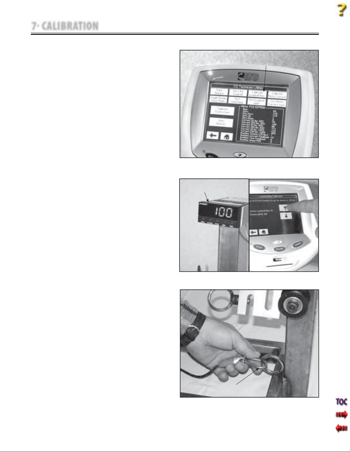
7 CALIBRATION
7.1 UNIT CALIBRATION (continued)
Tru-Trac and TX® Therapeutic Traction Unit
10. Hold onto Traction Cord and press Rope
Release to remove all slack from Traction
Cord.
11. Press Calibrate Load Cell Bias on the Touch
Screen. See Figure 7.6.
12. While watching the Strain Meter LCD,
Figure 7.7A, press the Up and Down
Arrow buttons, Figure 7.7B until 100 lbs is
displayed on LCD.
13. Press Back icon on Touch Screen to set
and accept calibration measurement.
NOTE:
Unit will display a validation message reading
"Returning to zero" while releasing tension on the
Traction Cord.
CALIBRATE LOAD CELL
BIAS
FIGURE 7.6
STRAIN METER LCD
14. Press Rope Release and pull enough Cord
out to connect the Accessory Hook to the
Lower Ring on the Calibration Fixture. See
Figure 7.8.
15. Allow excess Traction Cord to feed back
into unit and release Rope Release.
FIGURE 7.7A
ACCESSORY CLIP TO
LOWER RING
FIGURE 7.7B
FIGURE 7.8
54
Page 57
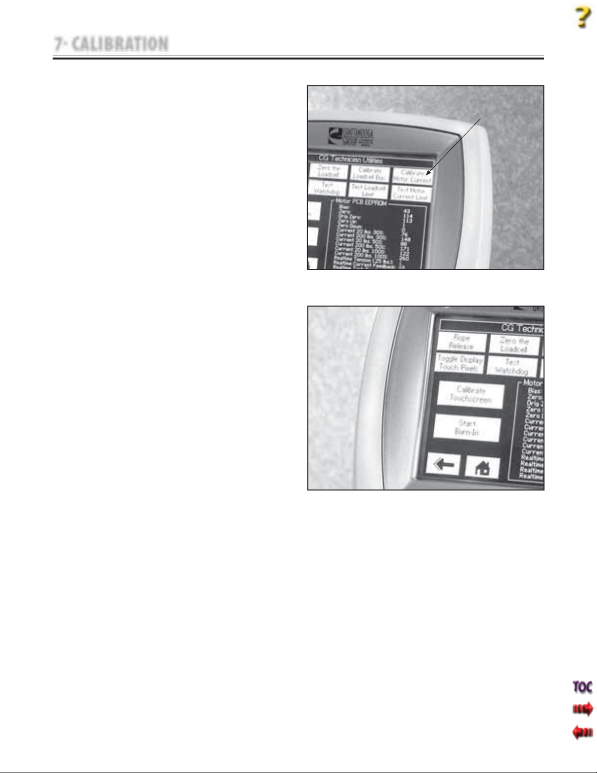
7 CALIBRATION
7.1 UNIT CALIBRATION (continued)
Tru-Trac and TX® Therapeutic Traction Unit
16. Press Calibrate Motor Current on the
Touch Screen. See Figure 7.9.
17. Unit will display "Motor Current
Calibration completed OK." When Motor
Current Calibration is complete. Touch
anywhere to continue.
7.2 TOUCH SCREEN CALIBRATION
NOTE:
If the unit is not in the Calibration Mode, refer to 7.1, C,
steps 6-7 to place unit in Calibration Mode.
CALIBRATE MOTOR
CURRENT
FIGURE 7.9
A. Equipment Required
None
B. Touch Screen Calibration Procedure
1. Press Touch Screen Calibration on Touch
Screen. See Figure 7.10.
2. Follow instructions on Touch Screen.
FIGURE 7.10
55
Page 58
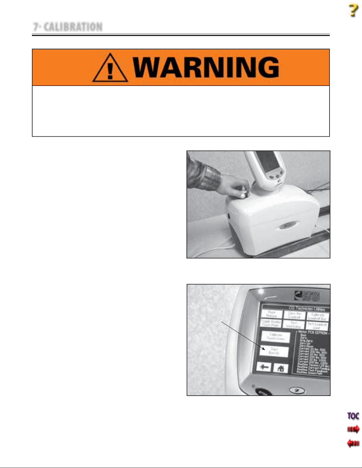
7 CALIBRATION
7.3 UNIT BURN IN
Certain removal and replacement procedures require that complete Unit Calibration and Burn In be performed
prior to placing the unit back into service.
Failure to perform either of these procedures after certain component or assembly replacement will void
warranty and may result in injury to patients and severe equipment damage.
The following Burn In procedure must be allowed to cycle for a minimum of two hours after Calibration
Procedures have been performed, but prior to placing the unit back into service.
A. Specifications
Burn In Intermittent Pull . . . 0-200 US lbs ±10%
Burn In Time Period . . . . . . . . .2 hours minimum
B. Equipment Required
Calibration Fixture with calibrated Strain Meter.
C. Burn In Set Up
1. Place unit on Calibration Fixture and secure
in position by tightening the unit Lock
Knob. See Figure 7.11.
2. Connect unit to an approved power source.
3. Turn unit On.
4. Release Traction Cord and connect
Accessory Clip to the Load Cell. See
Figure 7.2.
5. Zero Load Cell.
D. Burn In Procedure
1. Perform Burn In Set Up.
2. Press the Clinical Resources button.
3. Simultaneously press the STOP, Clinical
Resources, and PAUSE buttons to access the
Technical Screen.
4. Press Start Burn-In on the Touch Screen. See
Figure 7.12.
5. After unit has cycled for a minimum of two
hours, press the STOP button. Unit will
return to the Home Screen.
6. Set up unit for a 100 lb Static pull. Start the
pull and verify the readout for the Load Cell
is 100 lbs ±10%.
E. Burn-In Result
1. If Load Cell Readout is outside the specified
range during the Static pull, perform Unit
Calibration Procedure and Burn In
procedure. Refer to pages 51-55.
2. If Load Cell Readout is within Specified
Range during Static pull, unit is ready to be
placed into service.
START BURN IN
FIGURE 7.11
FIGURE 7.12
Tru-Trac and TX® Therapeutic Traction Unit
56
Page 59
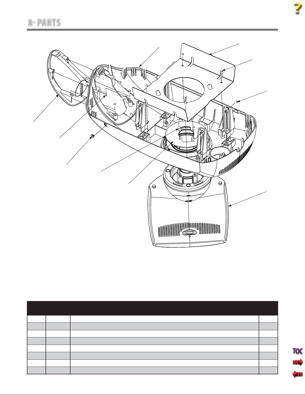
8 PARTS
8.1 TOP COVER ASSEMBLY
8
3
Tru-Trac and TX® Therapeutic Traction Unit
1
2
3
4
7
3
6
ITEM PART
DESCRIPTION QTY
NO.
1 47856 Top Cover 1
2 48007 Top Moulding Plate 1
3 27137 Screw 10
4 60803 Screw 4
5 48063 Touch Screen Assembly 1
6 48062 Turn Table Plate 1
7 47896 Hook Cover 2
8 47872 Cord Guide Cover 1
5
57
Page 60
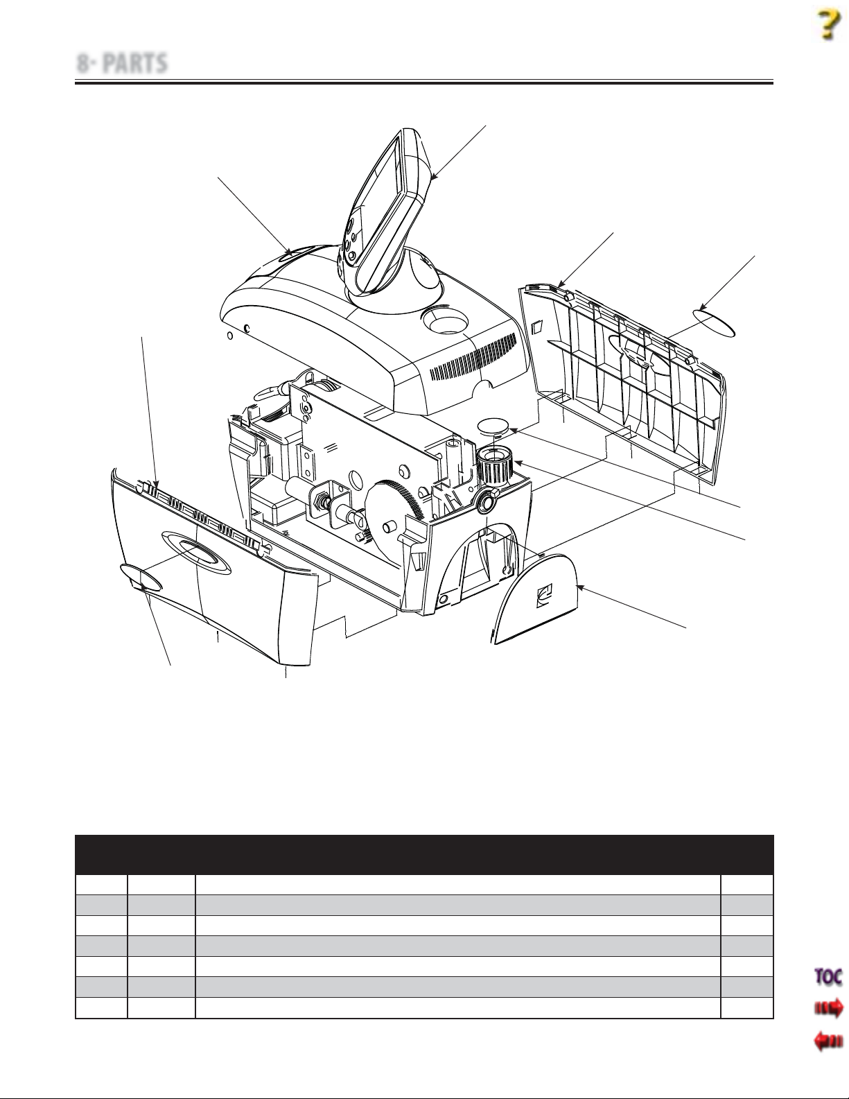
8 PARTS
8.2 SIDE COVERS
1
Tru-Trac and TX® Therapeutic Traction Unit
See Page 56
6-7
1
2
5
2
ITEM PART
DESCRIPTION QTY
NO.
1 47857 Side Cover 2
2 47884 Side Badge 2
3 47871 Knob Cap 1
4 47869 Lock Knob 1
5 27008 IEC Connector Cover 1
6 48113 Tru-Trac Badge (Model 4779) 1
7 48114 TX Badge (Model 4759) 1
3
4
58
Page 61
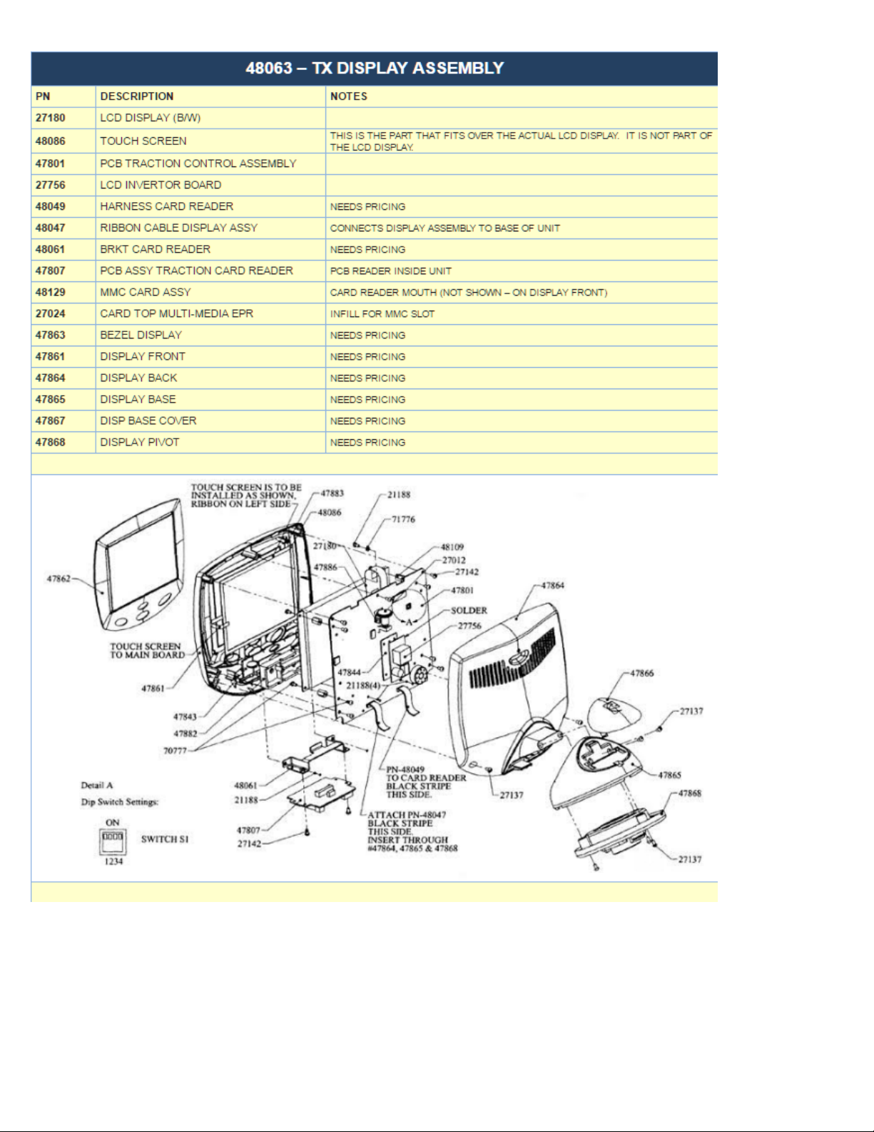
Page 62
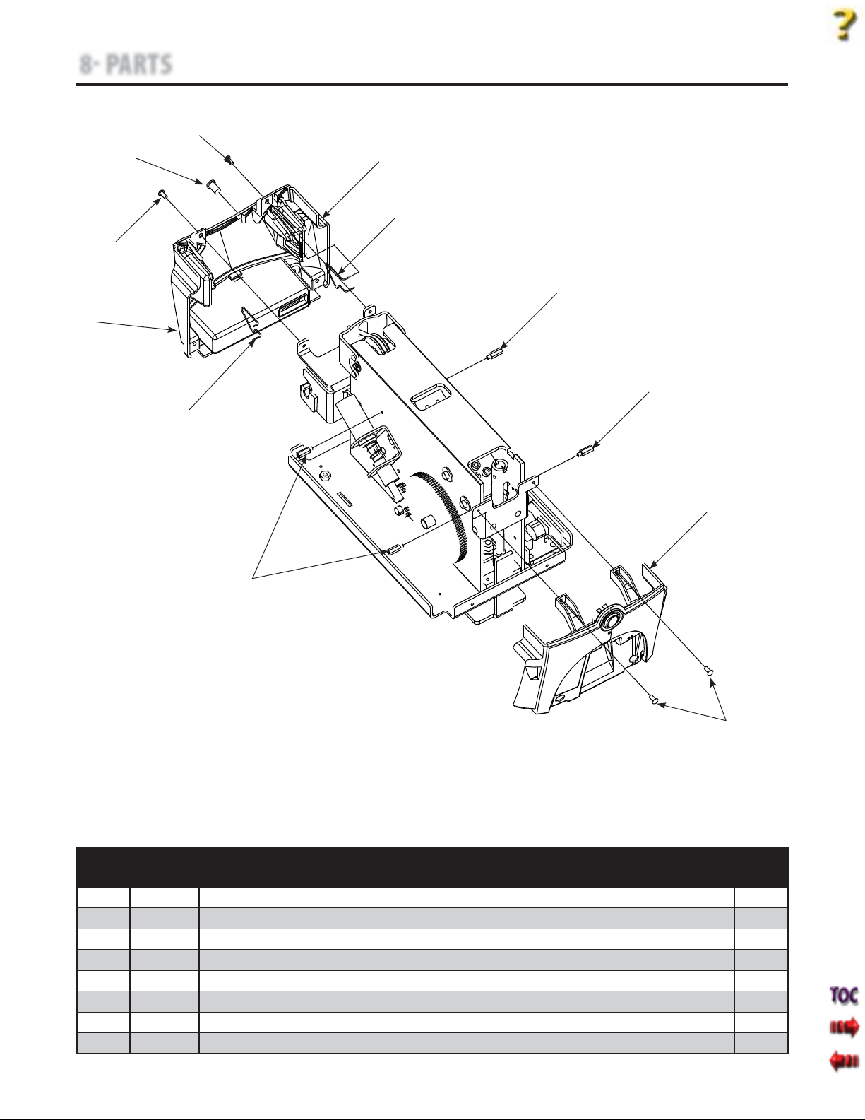
8 PARTS
8.3 FRONT AND REAR COVERS
5
Tru-Trac and TX® Therapeutic Traction Unit
8
1
2
5
3
7
3
6
4
1
3
ITEM PART
DESCRIPTION QTY
NO.
1 47858 Front Cover 1
2 48038 Left Spring 1
3 48070 Stand Off 4
4 48110 Rear Cover Assembly (includes wiring and hardware) 1
5 47851 Screw 8
6 48054 Right Spring 1
7 47878 Front Infi ll (Not Illustrated) 1
8 48040 Patient Switch Receptacle 1
5
59
Page 63
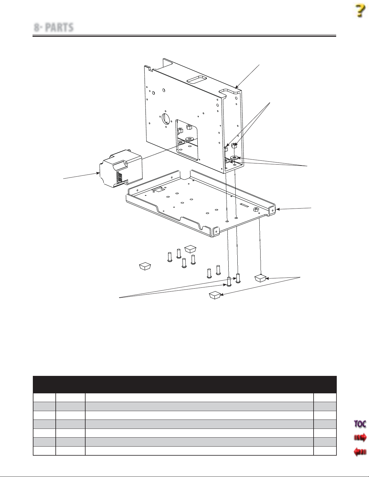
8 PARTS
8.4 BASE AND EXTRUSION ASSEMBLY
7
Tru-Trac and TX® Therapeutic Traction Unit
1
2
3
5
6
ITEM PART
DESCRIPTION QTY
NO.
1 47833 Extrusion 1
2 70208 Hex Nut 8
3 21387 Flat Washer 8
4 47832 Base Plate 1
5 60014 Anti Skid Feet 4
6 62951 Screw 8
7 48019 Motor Assembly 1
4
60
Page 64
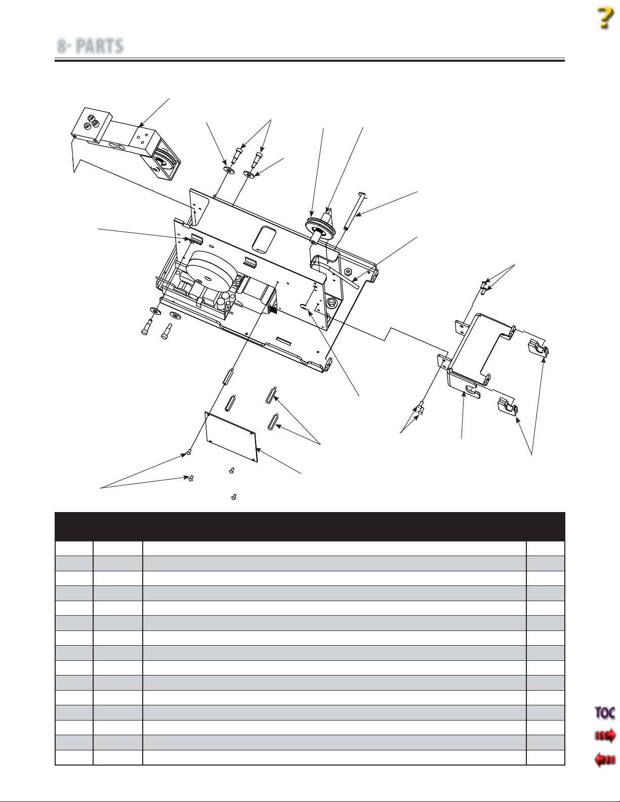
8 PARTS
8.5 CHASSIS ASSEMBLY
Tru-Trac and TX® Therapeutic Traction Unit
1
14
2
3
4
5
2
6
7
8
15
8
11
10
12
13
ITEM PART
DESCRIPTION QTY
NO.
1 48009 Load Cell Assembly 1
2 21387 Flat Washer 4
3 48102 Shoulder Bolt 4
4 70369 Top Guide Pulley 1
5 48078 Top Guide Mounting Spacer 2
6 47998 Top Guide Pulley Axle 1
7 48031 Traction Cord 1
8 47851 Screw 4
9 47889 Spring Housing 2
10 48097 Front Cover Mounting Bracket 1
11 47850 Stand Off 4
12 47803 Motor Control Board 1
13 70777 Screw 4
14 78155 Cable Guide 2
15 48008 E-Clip 2
9
61
Page 65
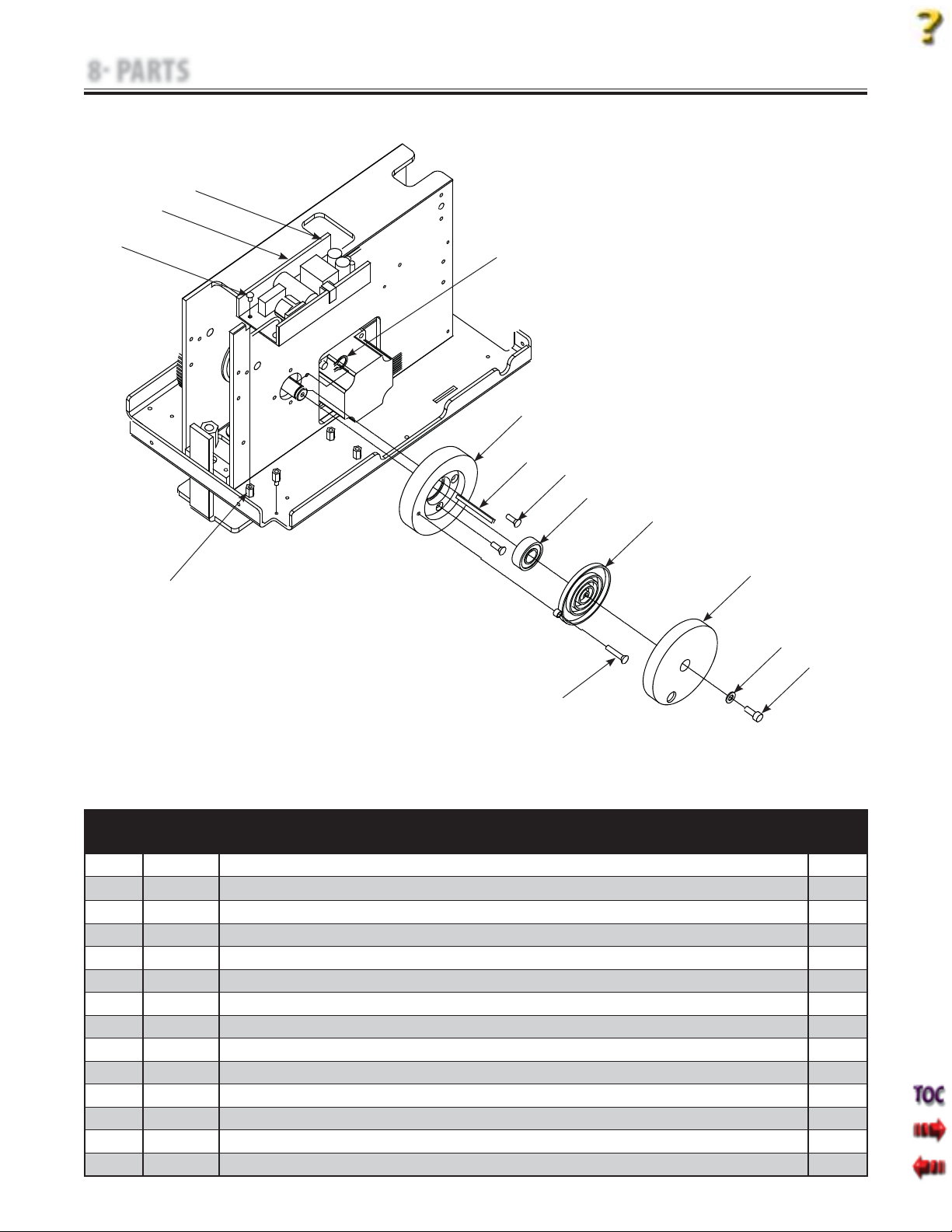
8 PARTS
8.6 TRACTION CORD SPRING ASSEMBLY AND POWER SUPPLY
14
13
Tru-Trac and TX® Therapeutic Traction Unit
12
1
2
3
4
5
6
7
11
8
9
10
ITEM PART
DESCRIPTION QTY
NO.
1 54758 Snap Ring 1
2 48106 Mounting Hub 1
3 73146 Square Key 1
4 48104 Screw 4
5 71934 Bearing 1
6 80653 Traction Cord Spring 1
7 80634 Spring Cover 1
8 21384 Flat Washer 1
9 47846 Screw 1
10 47823 Spring Mounting Screw 1
11 72559 Stand Off 4
12 31768 Screw 4
13 27592 Power Supply Shield 1
14 27265 Power Supply 1
62
Page 66
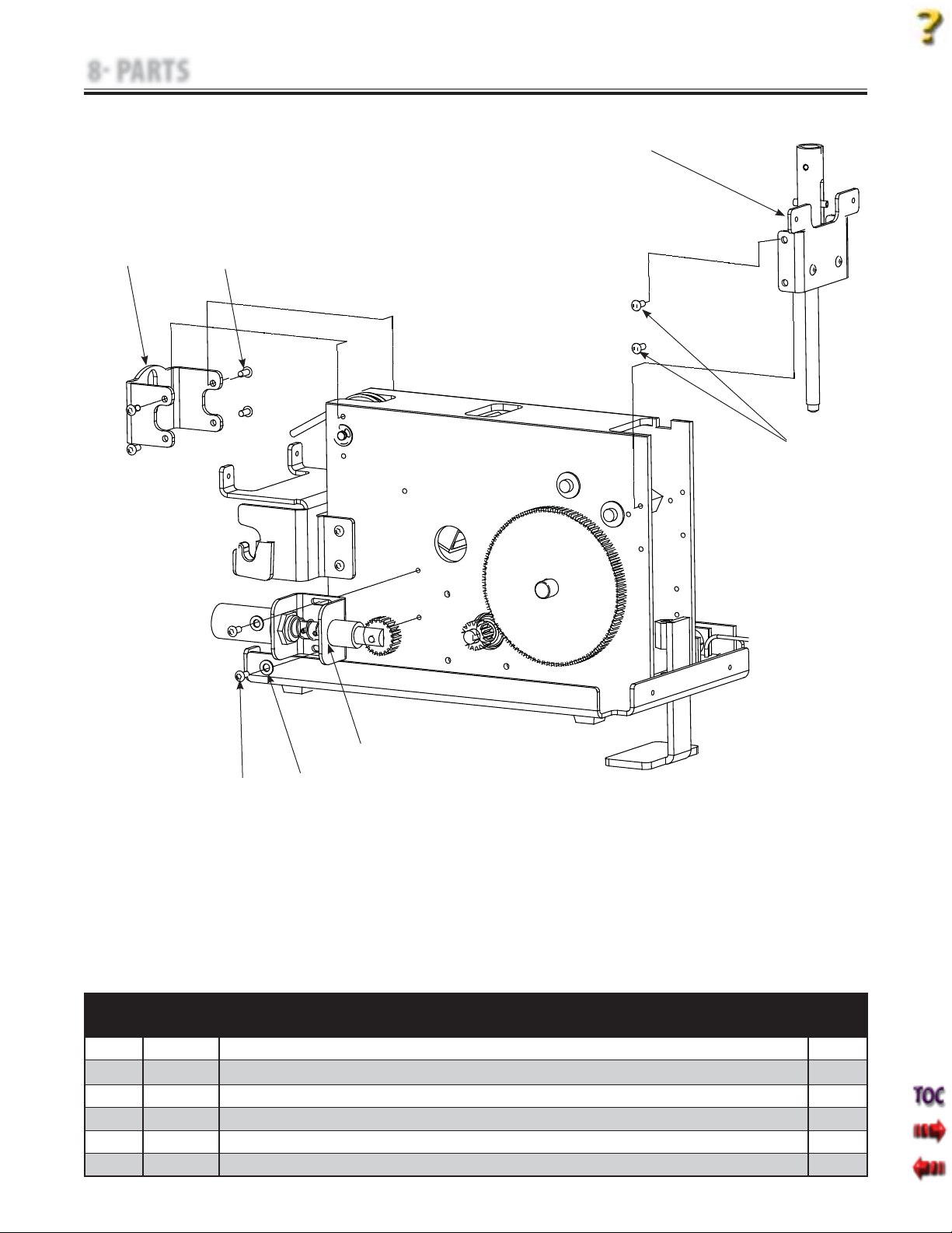
8 PARTS
8.7 SOLENOID AND CLAMP ASSEMBLIES
Tru-Trac and TX® Therapeutic Traction Unit
1
6
2
2
3
5
ITEM PART
4
DESCRIPTION QTY
NO.
1 48023 Clamp Assembly 1
2 47851 Screw 8
3 48014 Solenoid Assembly 1
4 21384 Flat Washer 2
5 47851 Screw 2
6 48097 Front Traction Cord Guide 1
63
Page 67
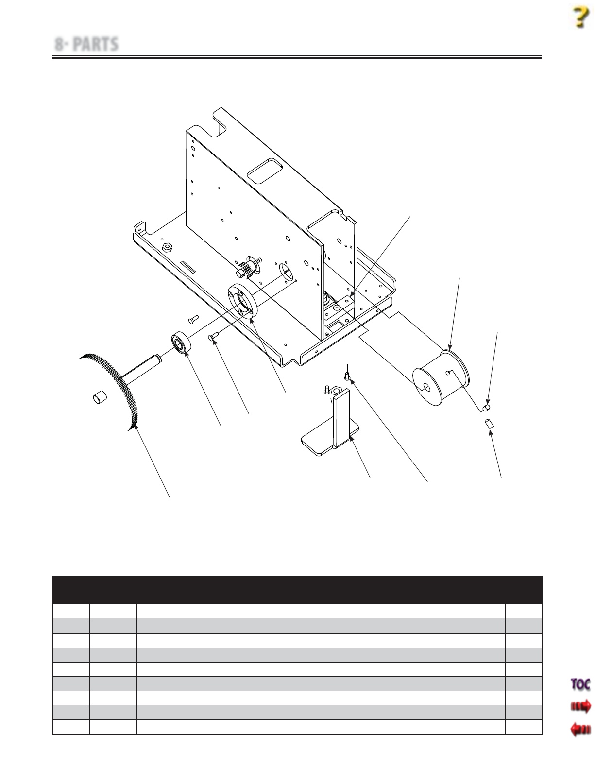
8 PARTS
8.8 LARGE DRIVEN GEAR AND SPOOL ASSEMBLY
Tru-Trac and TX® Therapeutic Traction Unit
1
2
3
6
7
8
5
4
9
ITEM PART
DESCRIPTION QTY
NO.
1 47997 Retaining Bar 1
2 48103 Spool 1
3 72017 Set Screw 2
4 47851 Screw 2
5 80158 Clamp Foot 1
6 47840 Hub 1
7 48104 Screw 4
8 71934 Bearing 1
9 47839 Large Driven Gear with Shaft Assembly 1
3
64
Page 68

9 SCHEMATICS
9.1 TRUTRAC AND TX TRACTION UNIT SCHEMATICS
A. General Information
1. Due to the complex nature of the technology utilized by Chattanooga Group, the recommended
PCB troubleshooting techniques are to determine “Bad Board” and board replacement only. No PCB
component level troubleshooting is recommended, nor will information or parts be supplied by
Chattanooga Group. Any PCB component level troubleshooting performed will be at sole risk and
liability of the Service Technician performing such troubleshooting techniques.
2. Once a particular PCB has been determined as bad, replace the PCB. Use only Chattanooga
Group replacement parts and hardware. Refer to Section 8 Parts for replacement parts and assemblies.
Tru-Trac and TX® Therapeutic Traction Unit
65
Page 69
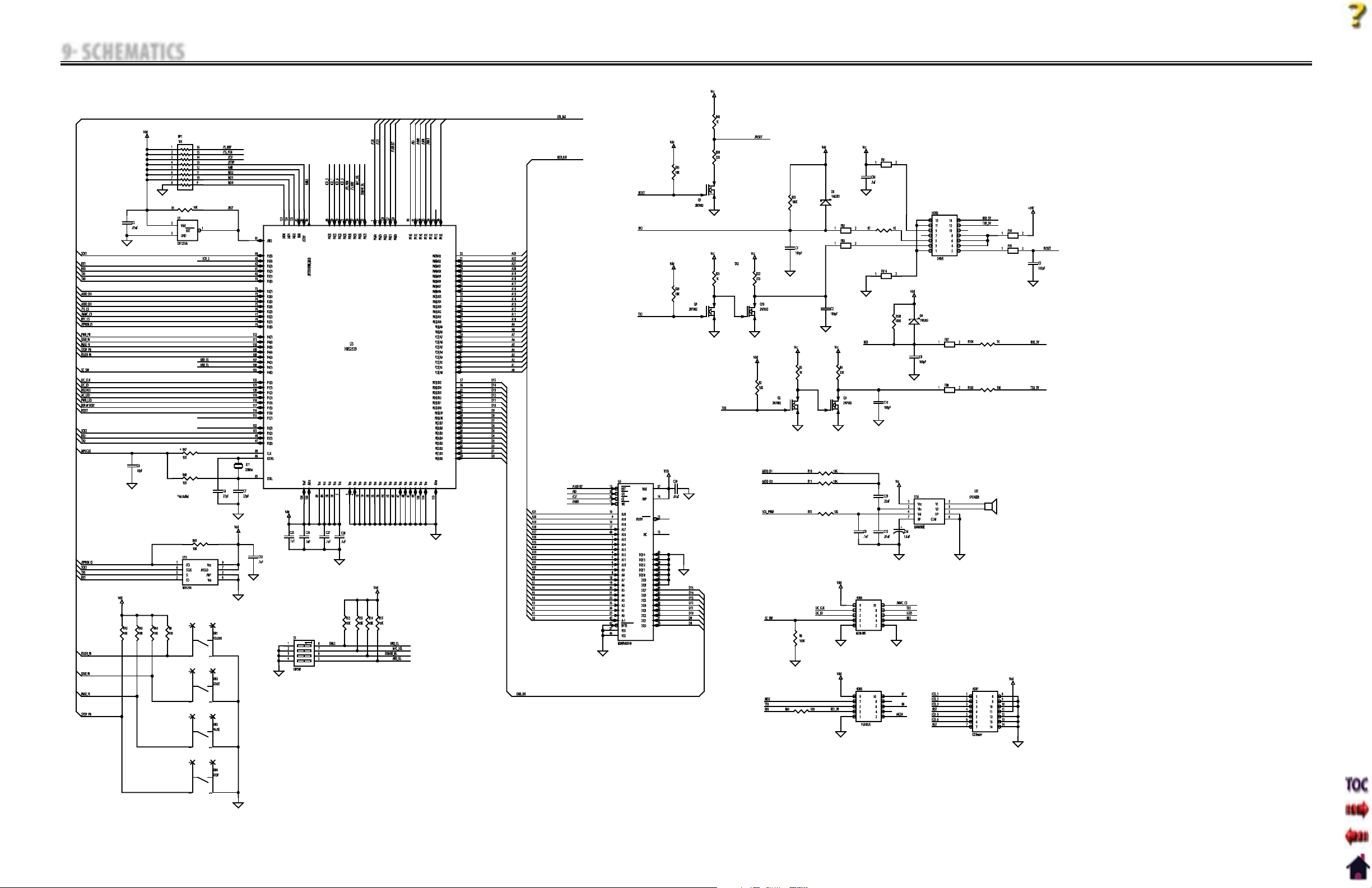
9 SCHEMATICS
Tru-Trac and TX® Therapeutic Traction Unit
66
Control Board- 47801
1 of 3
Page 70
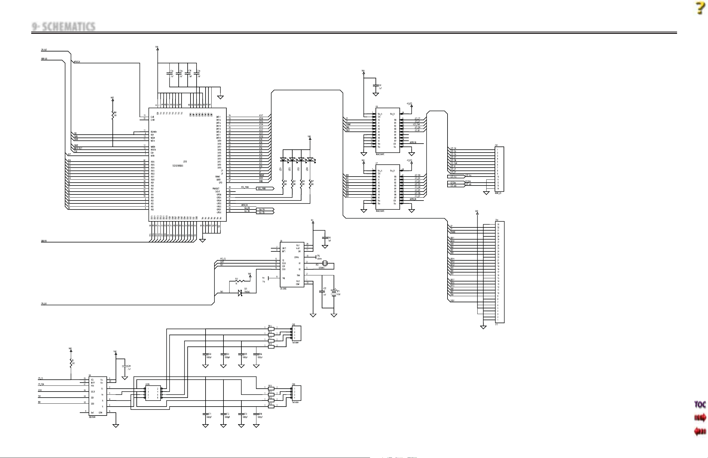
9 SCHEMATICS
Tru-Trac and TX® Therapeutic Traction Unit
67
Control Board- 47801
2 of 3
Page 71
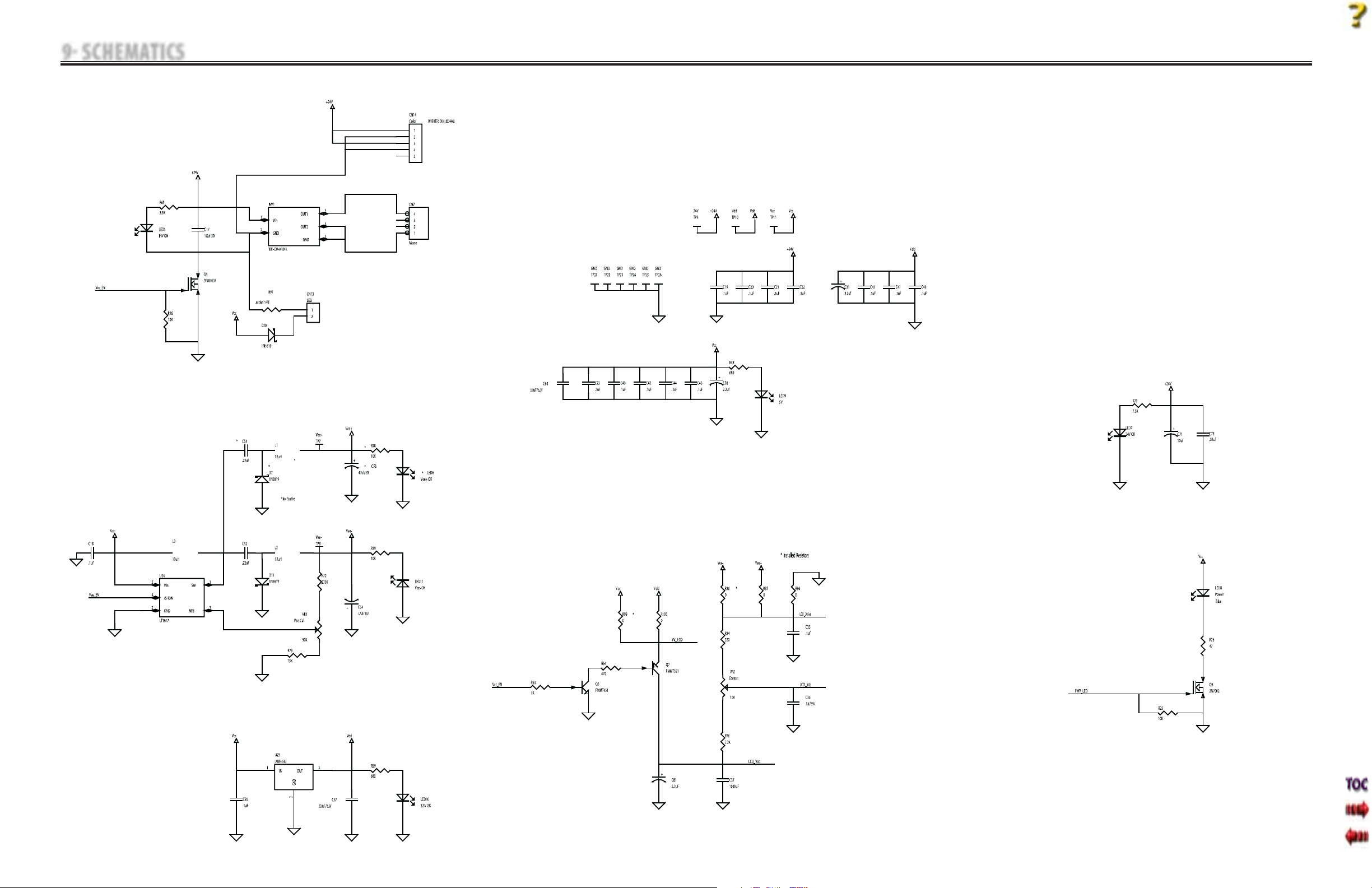
9 SCHEMATICS
Tru-Trac and TX® Therapeutic Traction Unit
68
Control Board-47801
3 of 3
Page 72
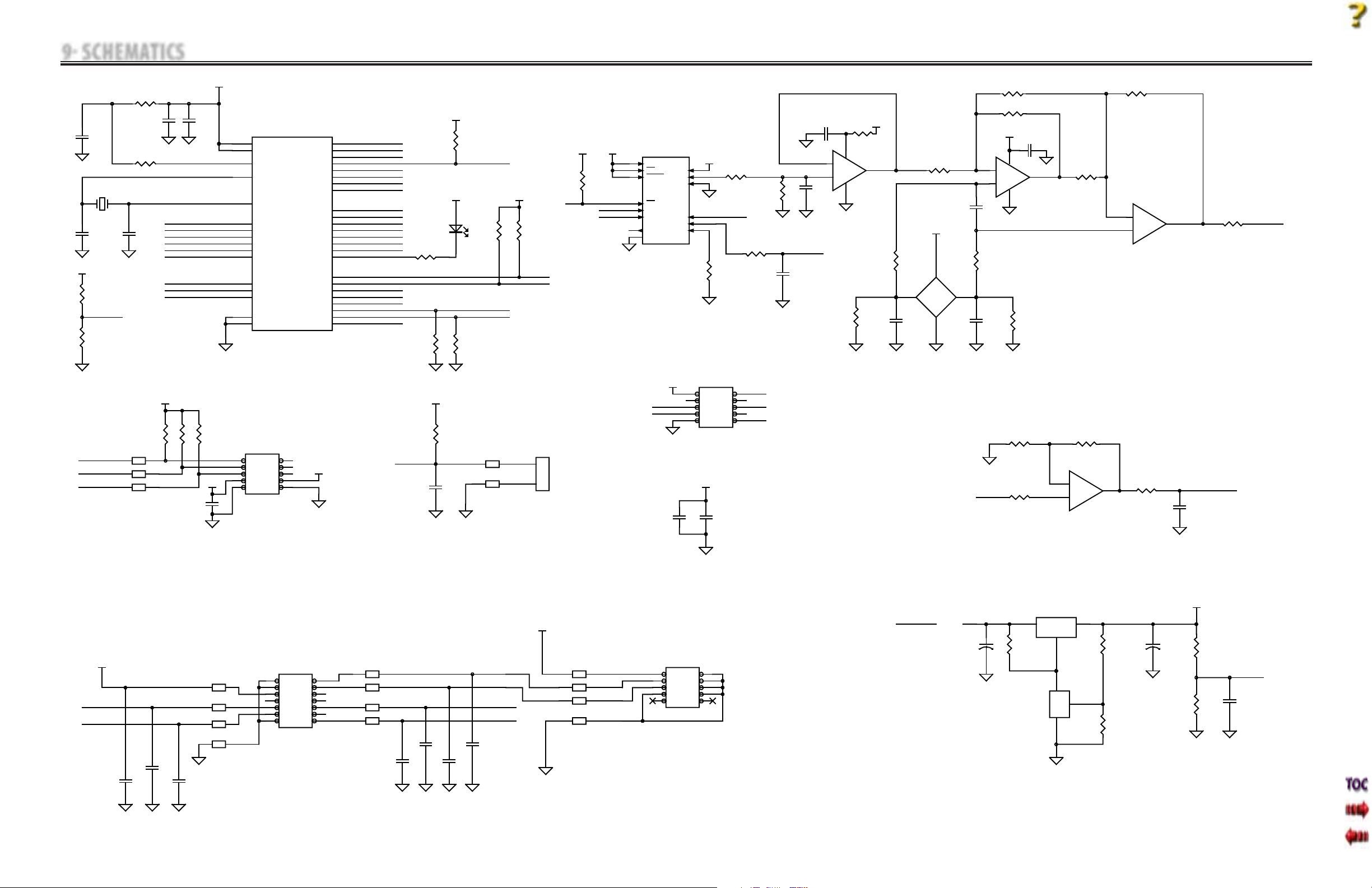
9 SCHEMATICS
Tru-Trac and TX® Therapeutic Traction Unit
69
Motor Control Board- 47803
1 of 2
Page 73
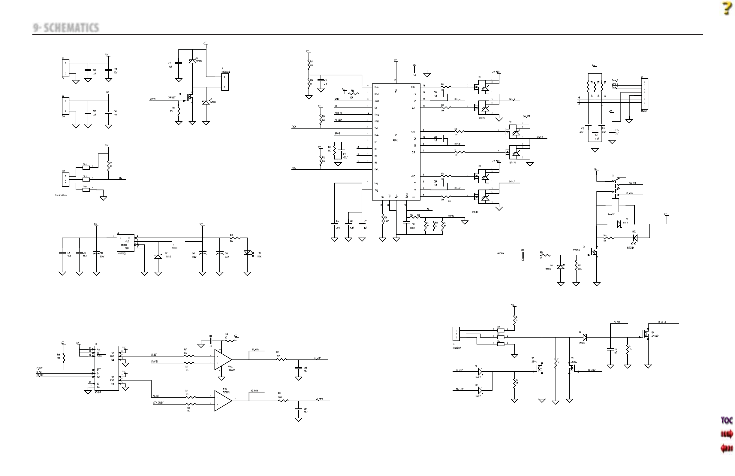
9 SCHEMATICS
Tru-Trac and TX® Therapeutic Traction Unit
70
Motor Control Board- 47803
2 of 2
Page 74
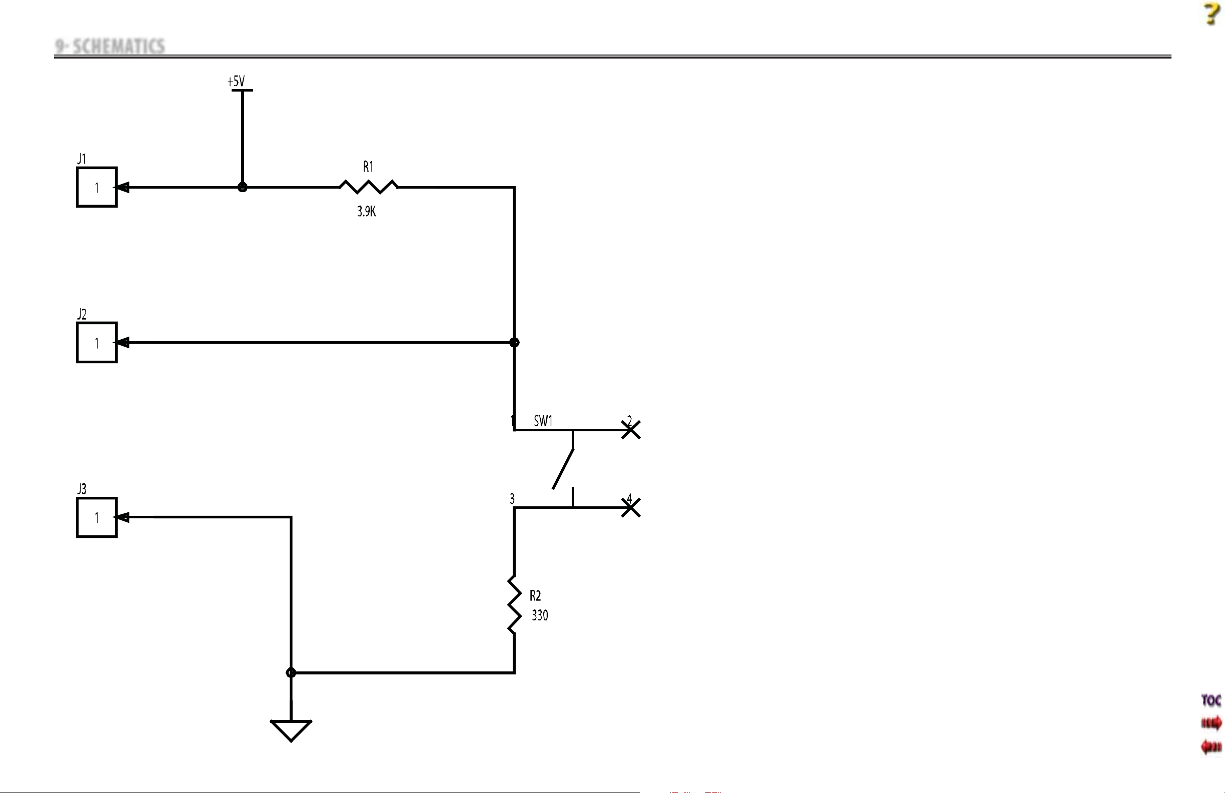
9 SCHEMATICS
Tru-Trac and TX® Therapeutic Traction Unit
71
Patient Interrupt Switch- 48056
1 of 1
Page 75
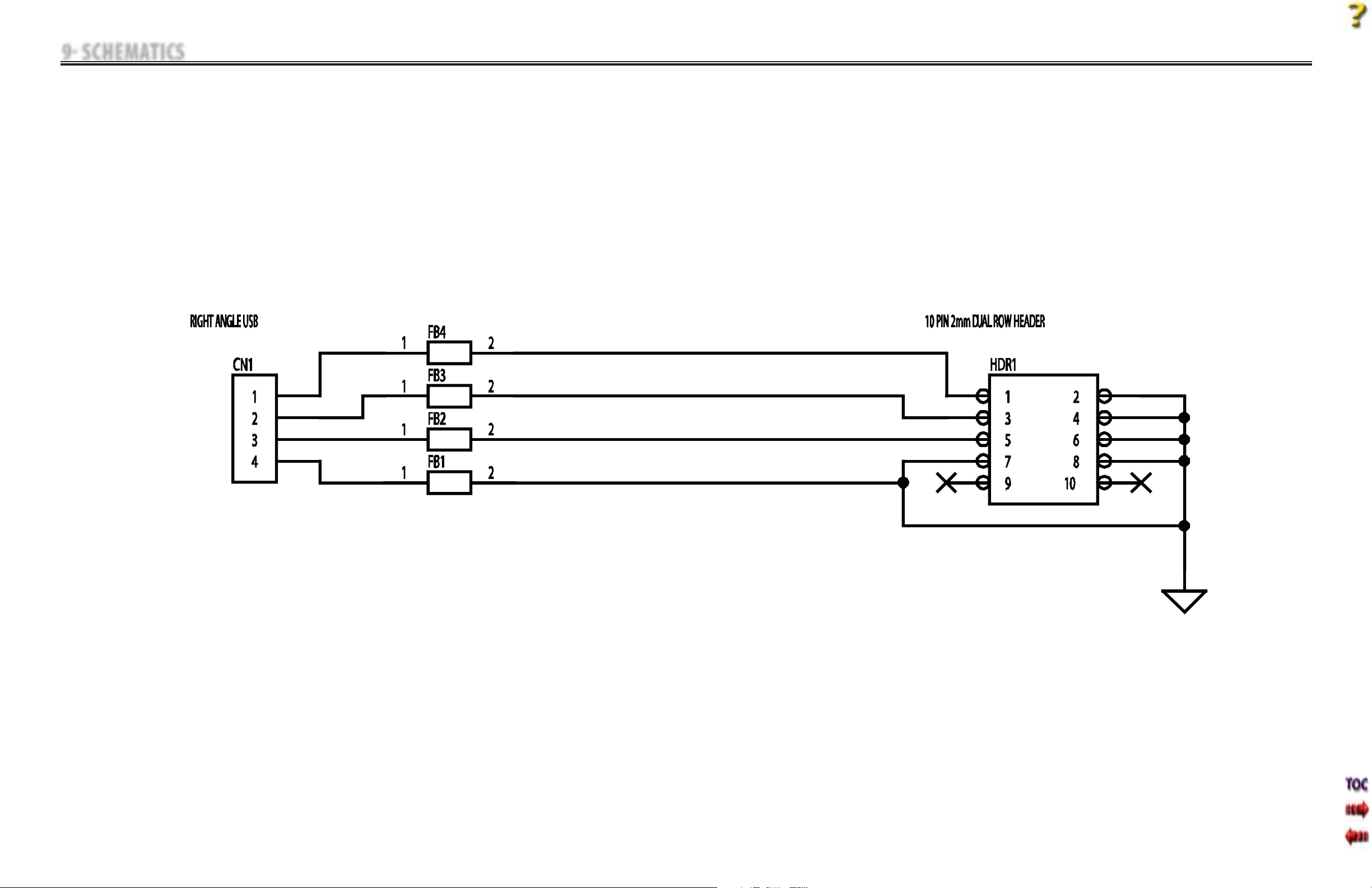
9 SCHEMATICS
Tru-Trac and TX® Therapeutic Traction Unit
72
Serial Interface- 47022
1 of 1
Page 76
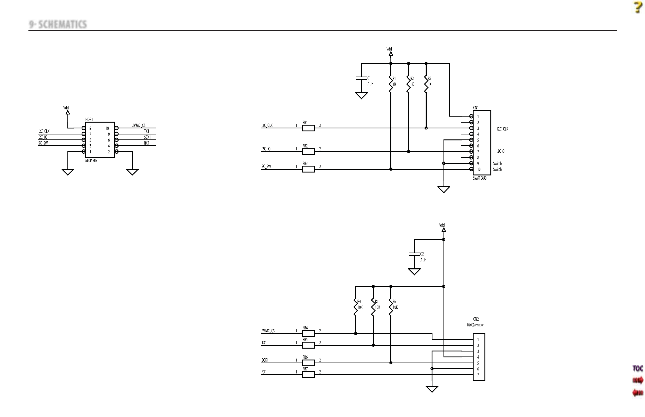
9 SCHEMATICS
Tru-Trac and TX® Therapeutic Traction Unit
73
Smart Card- 47807
1 of 1
Page 77
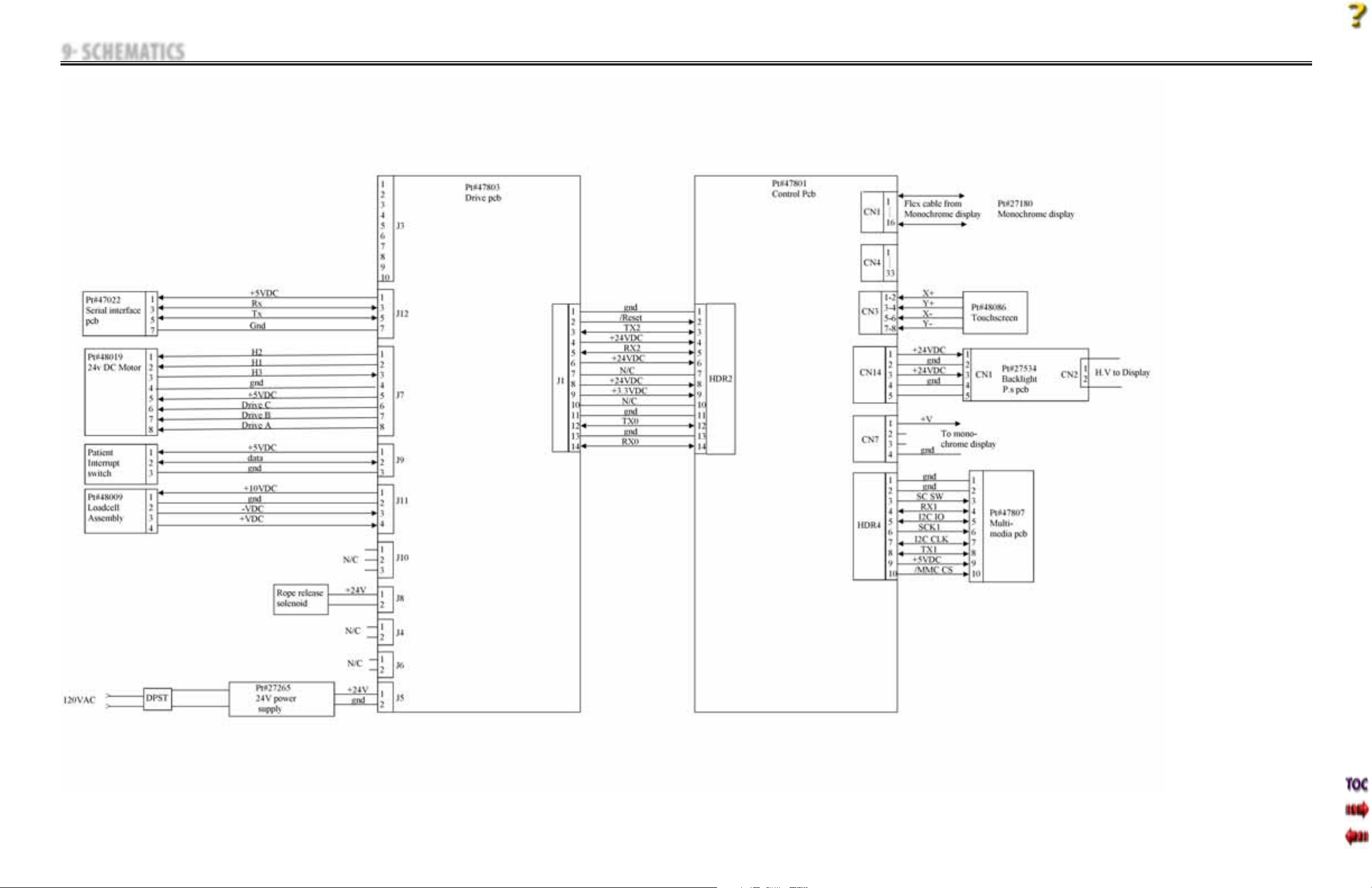
9 SCHEMATICS
Tru-Trac and TX® Therapeutic Traction Unit
74
Block Diagram
1 of 1
Page 78
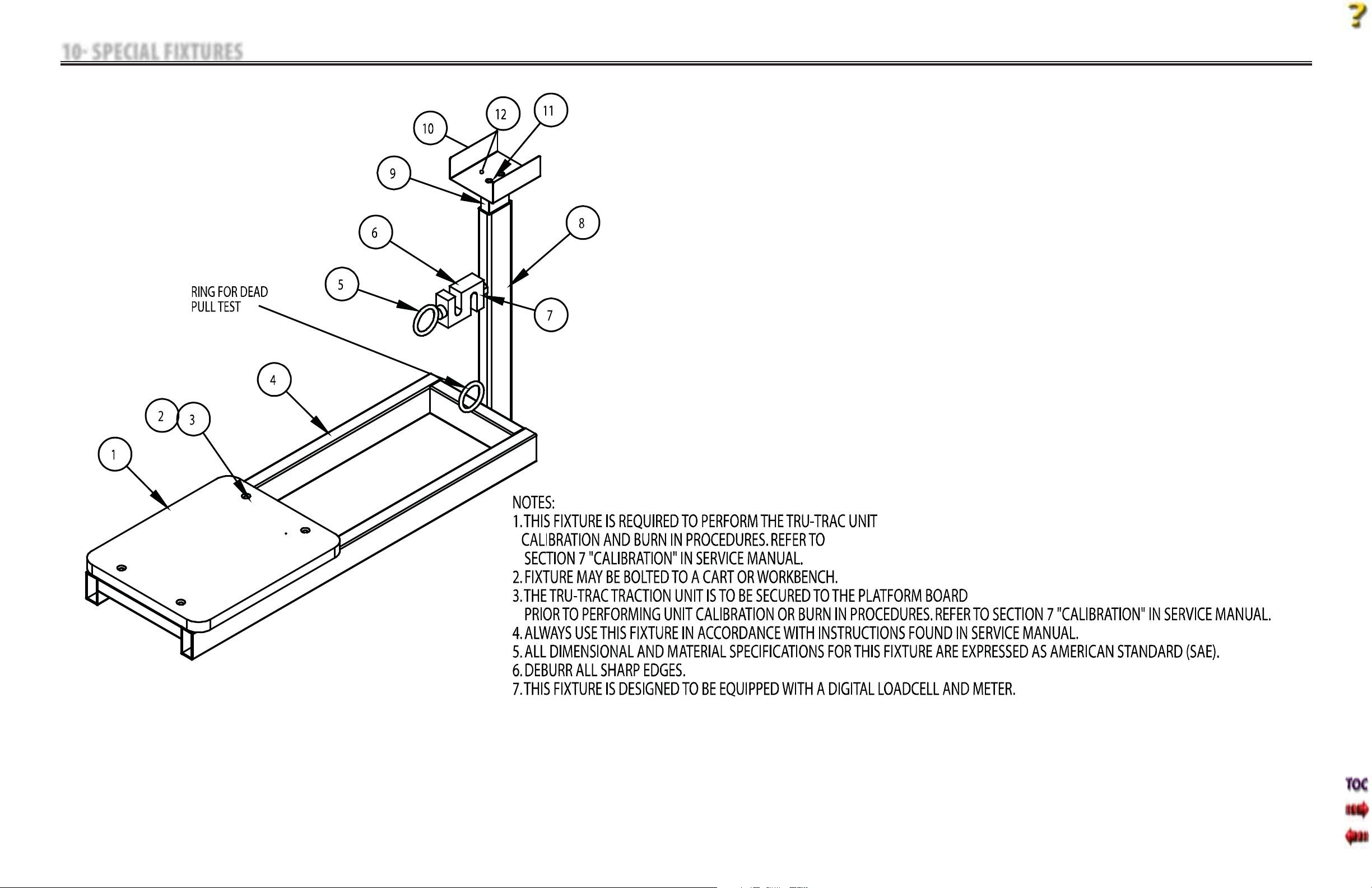
10 SPECIAL FIXTURES
Tru-Trac and TX® Therapeutic Traction Unit
75
Calibration Fixture
1 of 4
Page 79
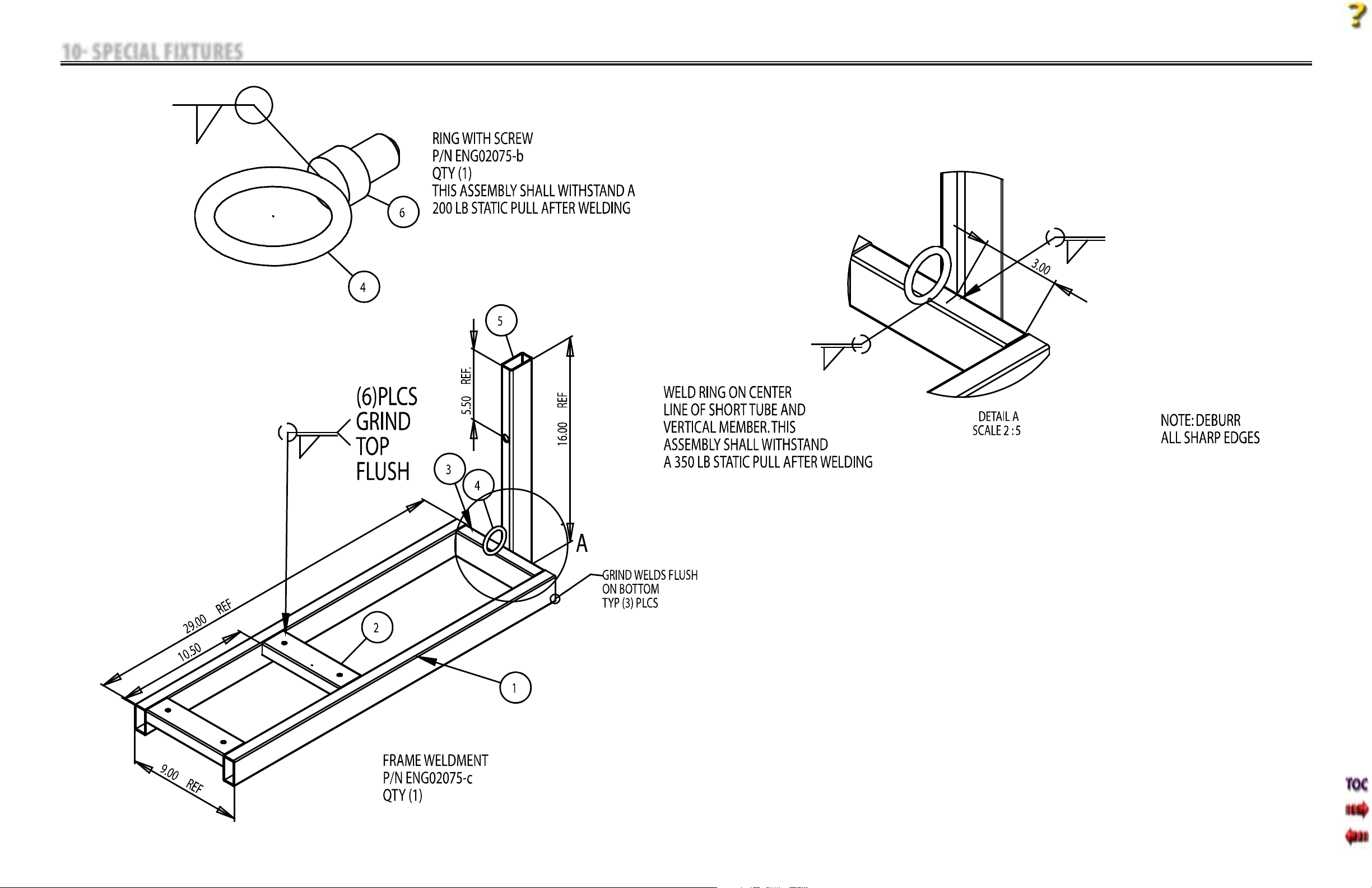
10 SPECIAL FIXTURES
Tru-Trac and TX® Therapeutic Traction Unit
76
Calibration Fixture
2 of 4
Page 80
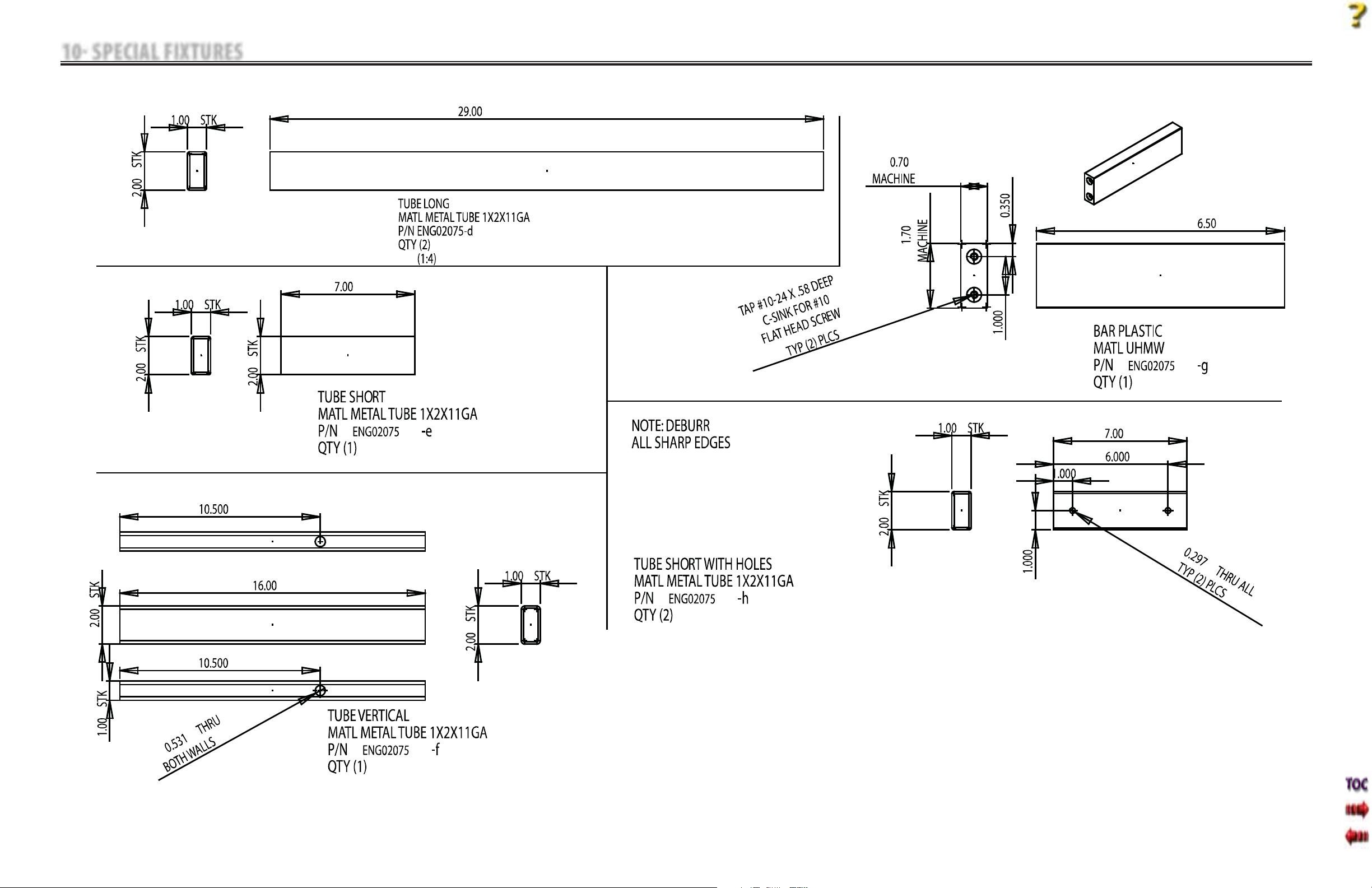
10 SPECIAL FIXTURES
Tru-Trac and TX® Therapeutic Traction Unit
77
Calibration Fixture
3 of 4
Page 81
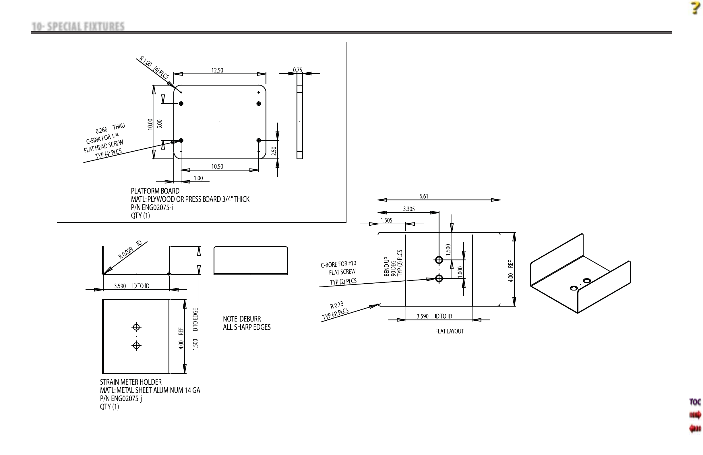
10 SPECIAL FIXTURES
Tru-Trac and TX® Therapeutic Traction Unit
78
Calibration Fixture
4 of 4
Page 82

11 WARRANTY
Chattanooga Group (“Company”) warrants that the Tru-Trac and TX Traction Unit (“Product”) is free of defects in
material and workmanship. This warranty shall remain in effect for two years (24 months) from the date of original
consumer purchase. If this Product fails to function during the two year warranty period due to a defect in
material or workmanship, Company or the selling dealer will repair or replace this Product without charge within
a period of thirty days from the date on which the Product is returned to the Company or the dealer.
All repairs to the Product must be performed by a service center authorized by the Company. Any modifications
or repairs performed by unauthorized centers or groups will void this warranty.
The warranty period for accessories is 180 days. Accessories consist of Patient Interrupt Switch shipped with the
unit.
To participate in warranty coverage, this Product’s warranty registration card (included with Product) must be
filled out and returned to the Company by the original owner within ten business days of purchase.
This Warranty Does Not Cover:
•
Replacement parts or labor furnished by anyone other than the Company, the selling dealer, or a certified
Company service agent.
•
Defects or damage caused by labor furnished by someone other than Company, the selling dealer, or a
certified Company service agent.
•
Any malfunction or failure in the Product caused by product misuse, including, but not limited to, the failure
to provide reasonable and necessary maintenance or any use that is inconsistent with the Product User
Manual.
Tru-Trac and TX® Therapeutic Traction Unit
COMPANY SHALL NOT BE LIABLE IN ANY EVENT FOR INCIDENTAL OR CONSEQUENTIAL DAMAGES.
Some states do not allow the exclusion or limitation of incidental or consequential damages, so the above
limitation or exclusion may not apply to you.
To obtain service from Company or the selling dealer under this warranty:
1. A written claim must be made within the warranty period to the Company or the selling dealer. Written claims
made to the Company should be sent to:
4717 Adams Road
P.O. Box 489
Hixson, TN 37343 USA
Phone: USA: (800) 592-7329
Fax: (423) 875-5497
Canada: (800) 361-6661
Outside USA: +1 (423) 870-7200
Outside USA Fax: +1 (423) 870-2046
2. The Product must be returned to the Company or the selling dealer by the owner.
This warranty gives you specific legal rights and you may also have other rights which vary from state to state or
location to location.
The Company does not authorize any person or representative to create for it any other obligation or liability in
connection with the sale of the Product. Any representation or agreement not contained in the warranty shall be
void and of no effect.
THE FOREGOING WARRANTY IS IN LIEU OF ALL OTHER WARRANTIES, EXPRESSED OR IMPLIED,
INCLUDING ANY WARRANTY OR MERCHANTABILITY OR FITNESS FOR A PARTICULAR PURPOSE.
79
Page 83

ISO 13485 Certifi ed
4717 Adams Road
P.O. Box 489
Hixson, TN 37343 U.S. A.
1-423-870-2281
1-800-592-7329 U.S. A.
1-800-361-6661 CANADA
+1-423-870-7200 OUTSIDE U.S.A
+1 423-870-2046 OUTSIDE U.S.A. FAX
chattgroup.com
© 2006 Encore Medical, L.P.
48131A
0413
 Loading...