

Page 1

6 0 K 2 5 X
OPERATORS
MANUAL
Page 2

ENCORE
Your mower is only as safe as the operator!
Operator carelessness or error may
result in serious bodily injury. Improper
maintenance of the machine may also
result in injury. Please read and follow
these instructions on Safe Operation and
be certain that anyone using this mower
fully understands and follows these
instructions.
WARNING:
DO NOT allow children to operate the
machine. DO NOT allow any adult to operate
the machine without proper instruction.
1. Familiarize yourself with the controls and know
how to stop the rider and mower deck quickly.
2. Inspect your work area carefully. Remove
debris from the area to be cut. Keep all
bystanders away from the mowing area.
3. Avoid contact with moving parts. Keep hands
and feet clear of the mower deck.
4. Never direct the discharge of material toward
bystanders nor allow anyone near the
machine while in operation.
7. Handle gasoline carefully. Use an approved
gasoline container. Fill the fuel tank, to within
1” from the neck, with good quality unleaded
gasoline.
8. Drive levers must be in the Neutral position
and the Blade Clutch must be disengaged
before starting engine.
9. Operator must wear proper shoes and
clothing, which may include safety glasses
and ear protection.
10. Mow only during daylight hours or under very
good artificial light.
11. The safety shield over the Grass Discharge
area must always be bolted in place and in the
DOWN position unless the Grass Catcher is
being used.
12. If a solid object has been hit by the blades
stop the machine and check for damage.
Repair or replace any damaged / broken part
prior to restarting the engine.
13. To avoid burns, DO NOT TOUCH the engine
or muffler immediately after operation.
14. Disengage blades when transporting and
when crossing walks and gravel roads.
5. The machine is not intended for highway or
street use. Never carry passengers!
6. Never tamper with safety devices or guards.
If a guard or safety device is damaged or
removed, replace it before operating the rider.
CAUTION:
Never add fuel to the tank while the engine
is running or hot. ALWAYS WAIT at least
five minutes before refueling and REFUEL
WITH THE ENGINE OFF. KEEP FUEL AWAY
FROM SPARKS OR FLAMES. WIPE AWAY
any fuel spillage BEFORE starting unit. Never
fill the fuel tank indoors. Wipe up any spilled
gasoline. Gasoline is highly flammable - NO
SMOKING.
15. Do NOT mow close to drop-offs, deep ditches
or other hazards. Do NOT stop or start
suddenly when going uphill or downhill. Mow
up and down the face of steep slopes; NEVER
mow across the face. If a steep hill must be
ascended, BACK up the hill, drive forward
when descending.
16. Reduce speed and exercise extreme caution
on slopes and in sharp turns to prevent tipping
or loss of control. Be especially cautious when
changing direction on slopes.
17. The Encore X-treme is NOT designed for
towing. Only factory approved Grass
Collection Systems are permitted.
2
Page 3
ENCORE
NOTE:
Make sure to
connect both
ground wires
Fig.1
Fig. 2
Before Operating Reminders
Fill engine crankcase as per engine
manufacturer’s manual. ENGINE DOES
NOT HAVE OIL IN CRANKCASE FROM
THE FACTORY. Add proper fuel to fuel tank,
open shut-off value.
The battery is now a gel-cell and will not
require acid.
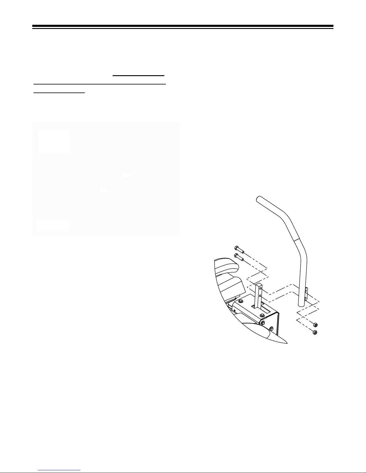
2. Open bolt bag and lay out bolts:
(2) – 5/16 X 1 HHCS
(4) – 5/16 X 1 1/4 HHCS
(2) – 5/16 Nyloc Nuts
(4) – 5/16 Whizlock Nuts
(4) – 5/16 Flat Washers
3. Take the 2 - 5/16 X 1 HHCS and 2 – 5/16
Nyloc nuts and bolt deflector into place.
4. Take the 4 – 5/16 Flat Washers and
4 – Nyloc Nuts and fasten seat to the seat
plate.
5. Attach the wire harness to the seat switch.
6. Take the remaining bolts and whizlocks
nuts and bolt control levers onto the
outsides of the handle mounts, adjusting
them according to operator comfort.
(See Fig. 2)
Before hooking up the ground wires make
sure that the engine has been filled to the
proper level with oil.
If battery will not turn the engine over after
hooking the wires up it may require a charge
for 15 to 20 minutes.
Raise the unit slightly and place a board under
each rear wheel.
With the deck in the raised position start the
unit and drive it off the pallet.
Once you are familiar with the contents of this
manual you are ready to mow with the finest
mower built!
ASSEMBLY
INSTRUCTIONS
Remove unit from crate, taking care to remove
inner boxes and the small parts box.
1. Remove deflector chute, bolt bag and
operator’s manual from main assembly.
STARTING ENGINE
Throttle control, ignition switch and choke
control are located between motion control
levers on the front panel under the front of
the seat.
Because of a built-in safety interlock system,
your machine will not start unless the seat is
occupied.
3
Page 4

ENCORE
STARTING ENGINE
(contiuned..)
TO START ENGINE: occupy seat, set park
brake, leave the motion control levers swung
out, move throttle control lever halfway to
operating position. Turn ignition key to
start position to engage starter, release the
key when engine starts. Ignition switch is
spring loaded and will return to run position
automatically.
Slowly return choke to run position once the
engine has started.
STOPPING ENGINE
TO STOP ENGINE: move throttle lever to
idle position and turn ignition key to “OFF”
position. If engine has been working hard or
is hot, allow engine to idle for a short period of
time before turning off key. This practice will
help cool engine before stopping.
IN CASE OF EMERGENCY engine may
be stopped by turning ignition key to “OFF”
position.
CAUTION:
Always remove the key and set the
parking brake when leaving the machine
unattended, even for just a few minutes.
PREVENT ACCIDENTS:
children or unauthorized persons an opportunity
to operate this machine.
Do not give
THE ENGINE WILL KILL IF:
1. The operator leaves the seat with:
a. The control levers out of neutral
(swung in).
b. The blades on (PTO).
c. The park brake is “OFF”.
d. All the above.
2. The park brake is set before the
control levers are in neutral
(swung out)
CORRECT TRANSMISSION
OPERATION TO GO
FORWARD OR REVERSE
The Encore Rider is equipped with a separate
pump and wheel motor for each wheel and are
controlled with “Motion Control Levers” , one
for each wheel.
To go FORWARD, push both levers
forward evenly.
To go in REVERSE, pull back on both
levers evenly.
To CHANGE DIRECTION, slowly
move levers to neutral and move the
lever forward in the direction you want
to go.
The further the levers are moved away
from the neutral position, the faster the
machine will travel. To turn the Rider
left or right, slow the speed of the
wheel in the direction you want to turn.
To STOP the Rider, return both levers
evenly to the neutral position.
SAFETY INTERLOCK SYSTEM
Your Encore Rider is equipped with a
Safety Interlock System that is designed
to help prevent possible serious injuries.
Understanding and maintaining this system is
vital, for maximum safe operation.
TO START ENGINE:
1. Blades (PTO) must be “OFF”.
2. Control levers in neutral
(swung out).
3. Park Brake “ON”.
4. Operator in seat.
WARNING:
THE ENGINE EXHAUST FROM THIS
PRODUCT CONTAINS CHEMICALS
KNOWN IN THE STATE OF CALIFORNIA
TO CAUSE CANCER, BIRTH DEFECTS
OR OTHER REPRODUCTIVE HARMS.
MOWING SPEED
The Encore Rider is designed to operate
most efficiently at maximum blade speeds.
4
Page 5

ENCORE
MOWING SPEED
(countinued...)
The running speed of the machine should
allow the mower blades to maintain this
maximum speed while mowing across turf.
Use a slower ground speed for cutting tall
grass, grass which is heavy with moisture, or
when mowing uphill. If ground speed is too
fast, or blade speed is too slow, mowing will
be uneven because mower blades will not be
able to lift grass into cutting position as the
mower passes.
Throttle control regulates speed of engine
as measured in RPM. This control SHOULD
NOT be used to control ground speed.
MAINTENANCE AND
SERVICE
1. Do not adjust mower or change
attachments unless the engine has been
stopped and the key has been removed.
2. Good maintenance, wiping up gasoline
and oil spills, will reduce potential fire
hazards.
3. To insure that the mower will remain in
safe operating condition, check and
tighten all bolts, nuts and screws.
Especially make certain the blade bolt/
nuts are always tightened properly.
4. Never adjust governor on engine to a
faster speed. The engine manufacturer
adjusts the engine RPM to the proper
setting.
5. Allow time for the engine to cool down
prior to storing mower. Do not store
mower or gasoline near any open flame
or where gasoline fumes may be ignited.
6. Always replace worn or broken parts with
genuine Encore repair parts purchased
from an authorized Encore dealer. Using
anything other than Encore repair parts
may void all Encore factory warranties.
OIL AND FILTER for
Change the hydraulic system filter at 250
hours. The hydraulic filter is located on the
hydraulic tank. Note: Clean filter area before
remounting to prevent contamination. Change
hydraulic oil in the reservoir yearly.
Use only a high quality Mobile 1 - 15w50 rated
oil. NOTE: Refer to the engine manual for
engine lubrication recommendations.
CAUTION:
DO NOT SPILL OIL OR GREAS E ON
BELTS.
TIRE PRESSURE
This vehicle has been designed to achieve
maximum operator comfort and ride. This
cannot be achieved without proper tire
pressure. A low pressure gauge is required to
check the front tires.
Front Tires - 14 PSI
Rear Tires - 20 PSI
NOTES:
The Encore Rider is driven and steered by
the rear wheels.
REAR TIRE CIRCUMFERENCE DIRECTLY
EFFEC T S THE TRACKI N G OF TH E
MACHINE.
If the machine will not drive in a straight line,
check air pressure and adjust accordingly.
5
Page 6
ENCORE
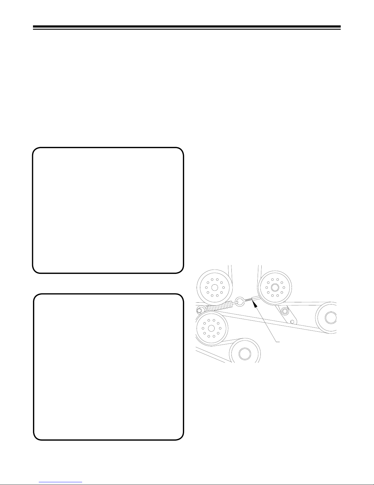
BELT TENSION
TURNBUCKLE
Fig. 3 - Turnbuckle Location
BATTERY
The gel-cell battery is maintenance free.
For longest service life, battery should be
kept clean by wiping it off with a paper
towel. Any corrosion around battery should
be removed by applying a solution of one
part baking soda to four parts water. A light
coating of grease or petroleum jelly may be
applied to all exposed terminal surfaces to
prevent corrosion.
CAUTION:
When servicing the battery or any other
part of the electrical system, or if the battery
must be removed for any reason, always,
disconnect negative (ground) cable FIRST
and reconnect it LAST to avoid possibility of
electrical shorts.
At temperatures below 32° F (0° C), full
charge state must be maintained to prevent
cell electrolyte from freezing and causing
permanent battery damage.
LUBRICATION
There are 5 grease points on the X52. One
on each caster, one on the caster swivel and
one on the foot pedal pivot. These are all
pre-greased from the factory. Environmental
conditions may be cause to vary frequency.
Before each use:
Clean engine chaff screen
Check engine oil and tire pressure
Every 40 hours:
Lubricate Casters (3 Pumps)
Lubricate Deck Height Foot-Pivot
(1 Pump)
Every 100 hours:
Lubricate Caster Swivels (3 Pumps)
Lubricate drive and pump control pivot
points
Check belt tension
BELT ADJUSTMENT
Remove key from the ignition switch. The
deck drive belt, which may be accessed
by removing the deck plate, (see fig.3) has
CAUTION:
Batteries produce flammable hydrogen gas.
Avoid creating sparks and open flames and
do not smoke when working near batteries.
Battery electrolyte solution is poisonous
and can be injurious to eyes, skin and
clothing.
IN THE EVENT OF AN ACCIDENT: Flush
affected area immediately with a solution of
one part baking soda to four parts water. If
baking soda is not readily available, flush
affected area with water. Notify physician
immediately.
a turnbuckle assembly to adjust spring
tension. Spring tension should be maintained
at 4” of spring stretch measuring the spring
coils. By turning the turnbuckle clockwise it
will increase tension, counter-clockwise will
decrease tension.
6
Page 7
ENCORE
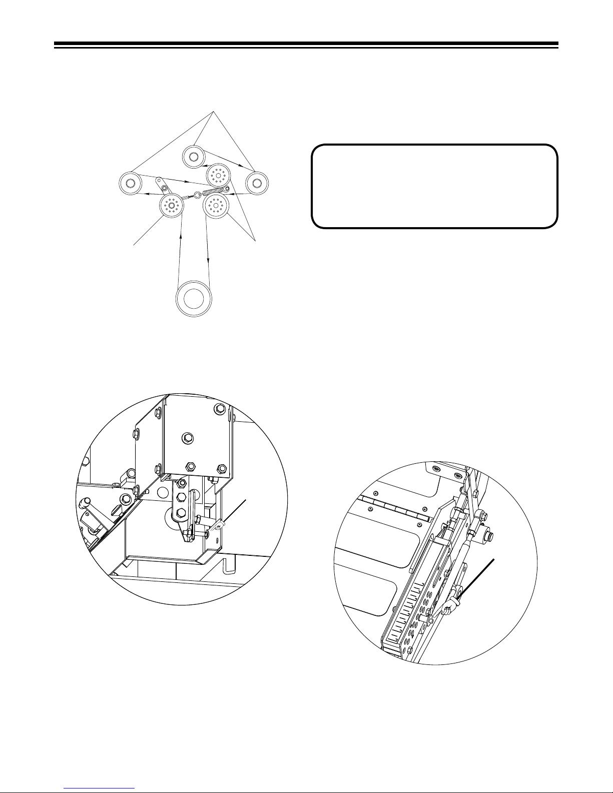
TENSION
IDLER
BLADE
IDLER
CLUTCH
PULLEY
Fig. 4 - Mower D e c k B e l t Layout
Fig . 5
Stop Bolt
Cut Pin
CUTTING HEIGHT
Fig . 6
BELT ADJUSTMENT
(continued...)
When installing a belt refer to fig. 4 as to the
route of the belt.
DRIVE ADJUSTMENTS
Steering and motion controls should be
uniform in all forward and reverse speeds.
Levers should automatically return to neutral
when released.
CAUTION:
TURN OFF ENGINE BEFORE MAKING ANY
ADJUSTMENTS.
To test drive operations:
Check air pressure in tires. Equal tire
pressure is critical for proper drive
operation.
Check linkage for excessive play.
• Raise rear of Rider until rear wheels
are off the ground. Safely block the
frame in this position.
• Put control levers in neutral lock
position (control levers swung
outward).
• Start engine.
TRACKING
To adjust the tracking there is a stop bolt
located on the bottom side of the steering
control. (See Fig. 5)
To adjust tracking simply loosen the lock
nut on the stop bolt and turn bolt clockwise
to increase speed or counter clockwise to
decrease speed.
DECK HEIGHT ADJUSTMENT
Mower heights can be adjusted by pushing the
foot pedal and by depressing the height of cut
pin and removing it. Select cutting height and
set pin accordingly.
7
Page 8

BLOCK OF WOOD
Fig. 7
BLADES
Fig. 8
When removing blades, block front end up or
run front wheels onto ramps. Stop engine,
remove key from the ignition switch, and
apply park brake. To remove, simply hold
blade bolt on bottom of the cutter housing
(See Fig. 7) and turn nut counter-clockwise.
Reverse procedure to reinstall. Blade bolts
should be torqued to 90 ft.lbs.
Note: Deck spring washer should always be
cup side up or cup side to blade to insure
proper torque on the blades.
CAUTION:
Mower blades are sharp and can cut you
during blade maintenance or adjustment.
Use suitable covering over cutting edges of
blades to prevent bodily harm.
ENCORE
WARNING:
NEVER RUN THE ENGINE IF THE
BATTERY IS REMOVED OR IF THE
BATTERY IS NOT CONNECTED TO
THE CHARGING SYSTEM. SERIOUS
DAMAGE TO CHARGING SYSTEM
COMPONENTS MAY RESULT.
Proper polarity is critical with an alternator
equipped charging systems. Always
disconnect battery cable (negative) before
working on any part of the electrical system.
Verify all components are connected correctly
before reconnecting ground cable (negative)
or damage to alternator system components
will result.
DECK LEVELING
ADJUSTMENT
Before checking the deck level makes sure
that tire pressures are inflated to the proper
level. Begin by setting the deck to a fixed
position and pointing the blades to the front
edge of the deck.
To obtain optimum mowing results, mower
blades should be kept sharp and well
balanced. File or grind blades evenly. Take
care to retain angle of original cutting edge.
CHARGING SYSTEM
An alternator is used to charge the battery.
The alternator charging system normally
requires no service other than periodically
checking that all exposed wiring and electrical
connections on the machine are clean, tight
and in good condition.
Measuring from the blade to the ground
on each side of the deck will give the best
reading. To adjust deck position loosen the
8
Page 9

DECK LEVELING ADJUSTMENT
(continued...)
bolt on the deck hanger bracket and move bolt
in the slot either up or down depending which
way you need to move the deck. You should
always maintain at least a 1/8 inch of deck
pitch from front to back. Also all four chains
must support the deck equally or must have
equal tension on them.
ELECTRICAL
The fuse box is located under the seat on a
panel mounted to the seat frame. There are
two (2) fuses that run the system, the top
fuse, which is a 20 amp, is the main fuse.
The second, a 15 amp fuse, takes care of
the electric clutch. The third and fourth slots
are blank extras. If there is a recurring fuse
failure, check the electrical system for a short.
ENCORE
Notes:
ELECTRICAL DIAGRAMS
X-Treme rider electrical diagram is on
page 10.
Notes:
9
Page 10

RED 14 GA.
423017
STARTER
RELAY
BLACK 16 GA.
BROWN 18 GA.
LT. BLUE 14 GA.
523034
PARK BRAKE
SWITCH
RED 12 GA.
ENGINE FUEL
SOLENOID
ENGINE
CHARGING
ORANGE 18 GA.
TO BATT. POS.
RED /BLACK STP. 18 GA.
ENGINE KILL
DK. BLUE 18 GA.
BLACK 16 GA.
TO BATT. GROUND
20 AMP FUSE
15 AMP FUSE
WIRE JUNCTION
52K23X
423351 WIRE HARNESS
ELECTRICAL DRAWING
ORANGE 12 GA.
LT. BLUE 14 GA.
RED 12 GA.
WHITE 16 GA.
FUSE
BLOCK
423027
IGNITION
SWITCH
RED /BLACK STP. 18 GA.
YELLOW 16 GA.
YELLOW 16 GA.
GREEN 18 GA.
GROUND TO ENGINE
593041
NEUTRAL
SWITCH
CLUTCH
CONN.
BLACK 18 GA.
BLACK 14 GA.
BLACK / WHITE 18 GA.
423030
MODULE
CONN.
BROWN 18 GA.
LT. BLUE 14 GA.
GREEN 18 GA.
523031
CLUTCH
SWITCH
523283
HOUR METER
DK. BLUE 18 GA.
GREEN 18 GA.
PURPLE 18 GA.
523030
SEAT
SWITCH
ENCORE
10
Page 11

ENCORE WARRANTY
For Encore Riding Mowers
This warranty extends to the original retail purchaser only and commences on the date
of original retail purchase. Any part of the Encore commercial mower manufactured by
Encore Mfg. Co., Inc. and found in reasonable judgment of Encore Mfg. Co., Inc. to be
defective in material or workmanship will be repaired or replaced by an Authorized Encore Dealer without charge for parts and labor. The Encore mower including any defective
part must be returned to an Authorized Encore Service Dealer within the warranty period.
The expense of delivering the mower to the dealer for warranty work and the expense of
returning it back to the owner after repair or replacement will be paid by the owner. This
warranty is limited to two years for frame, hydrostatic drive system (excluding hoses),
cutter housings, gearbox, and driveshaft. The warranty will be 2 years from the date
of purchase against defects in workmanship and materials (90 days for rental use) for
any Encore rider that is used for homeowner, commercial or any other income producing
purpose. Belts, batteries, and tires are warranted for 90 days against defects in materials
and workmanship. The deck warranty will be 10 years from the date of purchase against
defects in workmanship and materials (90 days for rental use) for any Encore rider that is
used for homeowner, commercial or any other income producing purpose.
Cutter housings, electrical components, hydraulic components and electric-clutch must be
returned before warranty will be paid.
The engine is covered by its respective manufacturer please refer to the manufacture’s
warranty statement that is included in the literature packet. Engine warranties should be
referred to the nearest authorized service outlet of the engine manufacturer.
The responsibility of Encore Mfg. Co., Inc. in respect to claim is limited to making the
required repairs or replacements, and no claim of breach of warranty shall be cause for
cancellation or recession of the contract of sale of any Encore mower.
Proof of purchase is required by both Encore and the servicing Dealer, before any warranty will be paid, and warranty work must be preformed by an Authorized Encore service
dealer.
This warranty does not cover any Encore mower that has been altered or modified so as
to adversely affect the intended use of the product, it operation, performance, or durability.
This warranty also does not cover any mower that has been subject to misuse, neglect,
negligence, accident or that has been operated in any way contrary to the operating instructions as specified in the Operators Manual.
Encore Mfg. Co., Inc. reserves the right to change or improve the design of any mower
without assuming any obligation to modify any mower previously manufactured.
Encore Mfg. Co., Inc. obligation under warranty is strictly and excessively limited to repair
or replacement of defective parts. Encore Mfg. Co., Inc. does not assume or authorize
anyone to assume for them any other obligation.
ENCORE MFG. CO., INC. CANNOT BE RESPONSIBLE FOR THE WAY YOU OPERATE, OR THE CONDITIONS IN WHICH YOU OPERATE THE MOWER. USE COMMON
SENSE AT ALL TIMES.
As of September 1, 2004 this warranty statement supersedes any warranty statement
published by ENCORE MANUFACTURING CO., INC.
Page 12

1006 B
All rights reserved. Contents subject to change. Part Number
,ENCORE MANUFACTURING CO., INC.
X-TREME
60K25X - OPERATORS MANUAL
933175
 Loading...