

Page 1

XP
PROFESSIONAL REMOTE ALARM SYSTEM
INSTALLATION
& USERS MANUAL
This unit is designed for professional installation only and must be installed by
an Encore authorized dealer. Please register this product at
www.encoreautomotivesystems.com.
Page 2
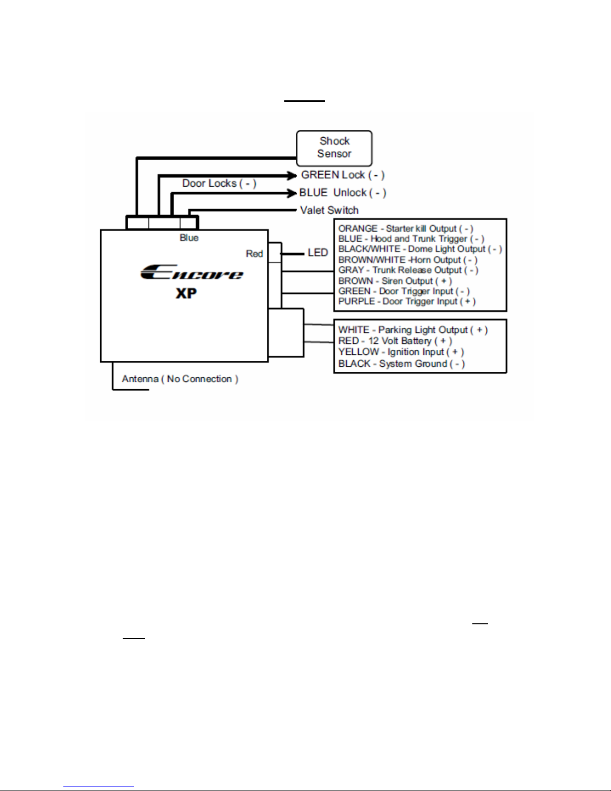
Wiring
4 PIN WIRE HARNESS:
White wire: POSITIVE PARKING LIGHT RELAY OUTPUT
Connect the WHITE wire to the parking light wire coming from the headlight switch.
Do not connect the WHITE wire to the dashboard lighting dimmer switch. (Damage
to the dimmer will result). The limitation of the WHITE wire is 10 AMP max. Do not
exceed this limit or damage to the alarm and parking relay will result.
Red wire : SYSTEM POWER (+12V CONSTANT) —
The RED wire supplies power to the system. Connect this wire to a stable constant
+12 volt source.
Yellow wire : 12 VOLT + WITH IGNITION ON
Connect this wire to a 12 Volt source when the ignition of the vehicle is in the ON or
RUN position.
Black wire : SYSTEM GROUND –
This is the main ground connection of the alarm module. Make this connection to a
solid section of the vehicle frame. Do not connect this wire to any existing ground
wires supplied by the factory wire loom, make the connection to the vehicle’s frame
directly.
Page 3
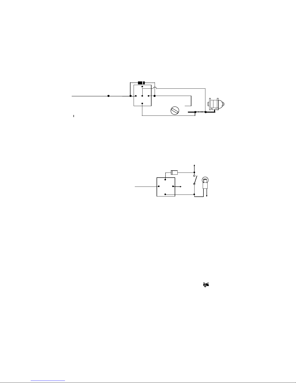
8 Pin Connector
30
“Start”
GREEN
wire
X
GREEN
“Acc”
Fuse
Orange wire – (-) 200mA Grounded Output When Armed –
This wire will become grounded when the alarm is armed. The current capacity of
this wire is 200mA. This output can control starter disable preventing any
unauthorized starting.
Orange wire
from control module
White wire
87
86
85
87a
YELLOW wire to
Ignition Switch
“On”
“Off”
Starter
Cut
Blue wire – Ground Instant Trigger Input (-)
This wire is the ground trigger input wire for hood and or trunk pin switches.
Black / White wire – (-) 200mA Dome Light Control Output –
This wire becomes grounded
when the dome light control
circuit is active. The current
capacity of this wire is 200mA.
This wire can control the
operation of the interior lights
when the system is disarmed.
An optional 10 Amps relay can
be used to this system for
interior lights operation.
Brown / White wire – (-) 200mA Horn Output –
This wire is provided to use the existing vehicle's horn as the alarm system's
warning audible device. It's a transistorized low current output, and should only be
connected to the low current ground output from the vehicle's horn switch. When the
system is triggered, the horn will sound
Gray wire – (-) 200mA Channel 3 (Trunk) Output –
This will become a 1 second pulse ground by pressing (button 3) on transmitter
for two seconds, the current capacity of this wire is 200 mA. This feature allows you
to remotely control trunk release or other electric device. (Relay may be required).
Brown wire – (+) SIREN OUTPUT –
This wire is provides power to the supplied siren. Connect the Brown wire to the
Red wire of the siren. Connect the Black wire of the siren to a stable chassis
ground.
BL/ White
86
87a
30
87
Courtesy
Door
Switch
+12V
85
Light
Page 4

Green wire – Negative Door Switch Sensing Input
Wire
( -
) Lock Pulse
( -
) Unlock Pulse
Blue Wire Door Unlock
wire and make connections. Be sure to program
+12V
Master Door
Splice
Splice
Cut the Existing Lock Wire
To Door
Lock
Motor
To Slave Door
Cut the Existing Unlock Wire
3 Pin Plug To Alarm
87a
87
30
87
Red +12V
Green Wire
Blue Wire
This wire is the ground trigger input wire for negative door pin switch. This wire is
connection for "grounding" type factory door pins locate the "common wire" that
connects the door pin switches. Make the connection of the GREEN Wire here.
The door trigger wires are vital for the operation of the optional anti-carjacking
mode.
Violet wire – Positive Door Switch Sensing Input
This wire is the positive trigger input wire for positive door pin switch. This wire is
connection for "positive" type factory door pins (typically FORD). Locate the
"common wire" for all door pins and make the connection of the VIOLET Wire here.
2-Pin Door Lock Connector:
Green wire – Lock Negative output
Blue wire - Unlock Negative output
Relays will be needed for positive door locking systems
NEGATIVE TRIGGER DOOR LOCK SYSTEM
Blue
Green Wire
5-WIRE ALTERNATING DOOR LOCK
Lock Switch
86
30
85
86
87a
85
Lock switches
VACUUM OPERATED CENTRAL LOCKING
3 Pin
Plug To
Alarm
Green Wire
+12V
Blue Wire
86
87a
30
87
85
86
87a
87
30
85
X
Door Switch
Cut
Compressor
Locking
Red (not used)
Green Wire Door Lock
To Exiting
Door Lock Relay
X
Master
Switch
VACUUM OPERATED DOOR
LOCKING SYSTEM:
TYPICAL OF MERCEDES BENZ
AND AUDI.
Locate the wire under the driver's kick panel.
Use the voltmeter connecting to ground, verify
that you have the correct wire with the doors
unlocked, the voltmeter will receive "12 volts".
Lock the doors and the voltmeter will read
"0 volt". Move the alligator clip to +12V and
the voltmeter will receive "12 volts". Cut this
door lock timer to 3.5 seconds.
(See Alarn Feature B – 3 Programming.)
Page 5

Button Function:
Transmitter Button System Function Remark
Button 1
Lock doors / ARM ARM
Button 1
Button
Button 2
Button 3 for 3 seconds
+ Buttons Together
*
Button 4
*
hold 2 seconds
Arm and Delete
shock Sensor
Car Locator Press While the
Unlock Doors /
DISARM
Pop Trunk Release Press 3 seconds
Silent LOCK /
UNLOCK
Activate Car-Jacking
If Programmed in
manual mode
Panic Press Unlock to stop
Keep Pressing
until the horn chirps a
second time
System is Armed.
Also Stop Panic and
trigger
Ignition in "OFF"
position.
Ignition in "ON"
position. Press again
stop manual
car-jacking
panic
Button 1: Arms the system and lock the door. Pressing this button while the system
is armed will activate the system's Car locator feature. You can disable the shock
sensor if this button is held until you hear 2 horn chirps.
Button 2: Disarms and unlocks the system. This button also stops Panic when
the car is in Panic Mode.
Button 3: Pressing this button for 3 seconds, activates the Pop Trunk Release if
installed
*
Button 4: Activates the Panic function. Press the Unlock to stop panic
mode. It will also initiate the anti-carjacking mode if manual mode has been
programmed.
Page 6

Pressing the and buttons together will silently arm and disarm the system.
Adding or replacing Transmitters.
To replace lost or stolen transmitters or to add additional transmitters into the system.
Please have all desired transmitters ready and follow the steps below.
Note: Up to 4 transmitters can be programmed to operate the system. To erase any
previously stored transmitter codes, be sure to program all 4 transmitter memory
locations.
To program the transmitter(s):
1. Turn on the ignition key On, Off, On, Off, and back On.
· The siren will chirp 3 times.
2. Press and hold the Override switch for 5 seconds.
The siren will chirp 5 times.
The LED will illuminate.
3. Press Button 1 on the first transmitter.
The siren will chirp once.
4. Repeat steps 3 and 4 for each transmitter (up to 4).
5. Turn off the ignition key.
Tamper Alert
If the system was triggered while away, the LED will flash to indicate which zone
system after disarming and turning on the ignition. The LED indication will repeat
LED Flashes:
1 flash ----- optional sensor
2 flashes ------ shock sensor
3 flashes ------ not used
4 flashes ------ door
5 flashes ------ trunk
10 flashes ------ main power interrupt or system was reset
example: flash-flash-pause-flash-flash pause = shock sensor
Remote Arming
The system monitors 3 independent areas (zones) while armed: doors, hood/trunk,
and shock sensor input.
To Arm the System:
1. Turn off the ignition.
2. Press Button 1.
The siren will chirp once.*
Page 7

The doors will lock.
The parking lights will flash once.
The LED will turn On, to indicate the starter defeat is activated.
3. 5 seconds after Arming, the LED will start blinking to indicate that the doors and
hood/trunk inputs are being monitored.
* During Arming, if the system detects a bad sensor or an open zone, the system
will chirp 4 additional times and ignore that input, but keep all other areas
protected.
Once Armed, the alarm will trigger when any of the following occurs;
The Ignition is turned ON
The doors are opened.
The hood or trunk is opened.
The shock sensor detects an impact to the vehicle.
When the alarm triggers, the siren will sound, the horn will honk, and the parking lights
will flash, If the system is triggered by the doors, or hood/trunk, the system will alarm
for 45 seconds. If triggered by the shock sensor input, the system will alarm for 30
seconds.
In the event the alarm is triggered and remains triggered continuously by the
same sensor or input during a single arming cycle, that sensor or input will be
automatically bypassed until the next time the system is armed.
If the Shock Sensor detects a light impact to the vehicle, the siren will chirp 5 times as
a warning indication.
Remote Disarming
To Disarm the System:
Press Button 2.
The siren will chirp twice.*
The doors will unlock,
The parking lights will flash twice and will remain ON for 30 seconds if
programmed
The dome light will turn on**.( Optional )
The LED will turn off.
* During Disarming, if the system was triggered while away from the vehicle the
siren will (chirp 3 times, and the parking lights will flash 3 times.
**If the optional Dome Light Activation Feature is installed
Page 8

Passive Arming
When programmed for the optional Passive Arming feature, the system arms itself
automatically, each time the ignition is turned off and all of the doors, hood, and trunk
are closed.
TO start the Passive Arming Process:
1. Turn off the ignition.
2. Open the door and exit the vehicle.
Once all doors are closed and the dome light is off, the LED will begin flashing
rapidly.
3. After 30 seconds,
The siren will chirp,
The parking lights will flash,
The doors will lock,*
The status LED will begin flashing.
4. The system is now armed.
* If the Passive Locking feature is selected.
If the Passive Arming with Countdown feature is programmed, the siren will chirp
every 2 seconds until the system passively arms.
Note: If the Passive Arming feature is enabled, the Automatic Rearming feature will
also be enabled even if it was not already programmed.
Panic Mode
In the event of an emergency, the transmitter's Panic feature can be used to instantly
trigger the arm.
To activate the Panic Mode:
1. Press Button 4.
The alarm will sound.
The parking lights will flash.
The doors will unlock* allowing access to the vehicle,
2. Press the Unlock Button to stop Panic Mode.
*If the ignition is on when the Panic feature is activated, the doors will lock for
personal safety.
Emergency Override
If the transmitter is lost or inoperable, the system can still be disarmed using the
following procedure. Before beginning this procedure be sure to have the ignition key
ready and know the location of the override switch.
TO Override the system:
1. Unlock the door using the key.
Page 9

2. Enter the vehicle.
, The system will trigger and the siren will sound.
3. Turn the ignition key to the ON position.
4. Press and hold the override switch until the alarm shuts off.
The system will disarm.
5. The vehicle will now be able to start.
Optional Coded Emergency Override
As an extra measure of security, the system is equipped with an optional Coded
Emergency Override feature. Once an Emergency Override Code is chosen and
programmed during installation, the system can No longer be disarmed using the
standard override procedure.
To Emergency override the system using the Code:
1. Follow steps 1-3 above.
2. Press the override switch a number of times equal to the Disarm code, and
continue holding for 10 seconds on the last press,
The system will disarm, If the code is entered incorrectly, turn off the ignition and
begin again.
To set the Emergency override Code:
1. Turn on ignition.
2. Within 5 seconds, press the valet switch 5 times.
The siren will provide one long chirp, indicating that you have entered
Programming.
3. Press the valet switch 3 times.
The siren will chirp each time the valet switch is pressed.
4. Within 5 seconds, press Button 3 on the transmitter.
The siren will chirp 3 times.
5. Press the valet switch the number of times equal to the desired code
(from 1-15 )
6. Turn off the ignition then arm the system.
7. Disarm the system using the new Override Code to permanently store the
new code.
Note: If the code set procedure is not properly performed, turn off the ignition and
begin again. The override code will not be permanently stored until the code is
used to disarm the system.
Page 10

Valet Mode
The Valet Mode temporarily disables the security system so the vehicle may be
operated by a mechanic or parking attendant.
To activate or deactivate the Valet Mode:
1. Turn on the ignition.
2. press and hold the override switch for 5 seconds.
The siren will chirp once and the LED light will stay ON to conform the Valet
Mode is on.
The siren will chirp twice and the LED light will turn OFF to conform the Valet
Mode is off.
3. Turn off the ignition.
While in Valet Mode the remote transmitters will continue to lock and unlock
the doors, and operate the optional auxiliary functions.
Battery Replacement
Your Remote Transmitter uses A 12 volt batteries (type CR2016), which will
require replacement in time. Depending on the amount of use, the battery may
last up to one year or more before it needs replacement.
When the battery needs replacing, the system's operating range will decrease or
the transmitter LED may not be as bright,
In order to change the battery, separate the top and bottom halves of the case.
While replacing the battery make sure that the positive and negative terminals
are positioned correctly, then carefully reassemble the transmitter case.
Ignition Controlled Door Locks
For added safety, the Ignition Door Locking feature allows vehicles equipped with
power door lock systems to automatically lock the doors when the ignition is
turned on, and unlock the doors after the ignition key is turned off. If a door is
open when the ignition is turned on, the ignition locking feature is disabled to
protect against locking the keys inside the vehicle.
Dome Light Activation ( Optional )
If the optional Dome Light Activation feature is installed, the dome light will turn
on when the system is disarmed using the Remote Transmitter. The dome light
will remain on for 30 seconds or until the ignition is turned on.
Remote Shock sensor Disable
When parking the vehicle in areas susceptible to unwanted disturbance from
animals or strong weather conditions that could cause the Shock Sensor to
trigger, the sensor can be temporarily bypassed using the Remote Transmitter,
preventing possible false alarms.
Page 11

To disable the Shock Sensor:
1. Arm the system normally and continue holding the lock button until a
second chirp is heard. The siren will chirp a second time and the parking
lights will flash 1 extra time to indicate the sensor is disabled.
The sensor will remain disabled until the next arming cycle.
Silent Arming/Disarming
The system can be programmed to operate without Arm and Disarm chirp
indications. When programmed for full-time silent operation, the siren will sound
only when the system is triggered.
The system is also capable of temporary silent operation when needed. Pressing
button 1 and 2 together will bypass the chirp conformations for Arm/Disarm and
allow one-time silent operation.
Note: The open zone warning chirps will not be bypassed when the system is
Armed or Disarmed silently.
Anti-carjacking protection
For a higher level of personal security, the system is equipped with three
programmable Anti-Carjacking modes. When any Anti-Carjacking mode is
triggered, the parking lights will flash twice and the LED will flash to confirm
activation. After 90 seconds the siren will begin chirping for 15 seconds as a
warning prior to entering full alarm mode. During the full alarm mode, the siren
will sound, the parking lights will flash, and the horn will honk for up to five
minutes or until the system is reset.
Manual: When selected, activating the button 4 will automatically trigger the
Anti-Carjacking feature; Press the button 4 again to reset the Manual Anti-Car
jack mode.
Passive (recommended if carjacking is selected): When selected, the
Anti-Carjacking feature will activate whenever a door is opened while the ignition
is on. To turn OFF the anti-carjacking feature press the Valet switch for 4
seconds. If triggered, Turn the Ignition OFF the then ON again and press
the Valet switch for 4 seconds to reset the Passive Anti-Carjacking mode.
Stop the vehicle in a safe place before turning OFF the ignition.
Full-time: when selected the anti-carjacking will automatically activate each time
the ignition is turned ON. To turn OFF the anti-carjacking feature press the
Valet switch for 4 second. If triggered, Turn the Ignition OFF the then ON
again and press the Valet switch for 4 seconds to reset the Anti-Carjacking
mode. Stop the vehicle in a safe place before turning OFF the ignition.
Full time anti carjacking is not recommended and the system will have to be
disarmed each time before the vehicle is driven.
Page 12

Shock Sensor: Adjustment
The two stage shock sensor is to be installed under the driver’s side dash as close to
the middle of the vehicle as possible. It has two adjustments.
One for the first stage known as warn away. This will trigger a few horn and siren
chirps if the vehicle has sensed a small impact.
The main or second stage will trigger on a heavier impact and put the system in full
alarm mode.
Both of these zones are independently adjustable with a small standard screwdriver
at the shock sensor.
Clockwise = MORE SENSITIVE Counter Clockwise = LESS SENSITIVE.
When the ignition of the vehicle is in the OFF position, The
LED can be used to adjust the sensor. The LED of the
system will flash slightly every time the sensor detects impact.
Please note that the interior LED will be ON solid when the
Ignition is OFF and any trigger is present. This will
happen if the doors are open or if the shock sensor is
showing trigger.
SYSTEM PROGRAMMING:
Entering System Programming
To enter System Programming;
1. Turn on ignition.
2. Within 5 seconds, press the valet switch 5 times.
The siren will provide one rapid chirp, indicating that you have entered
Programming. The horn will not sound entering programming mode but
the LED will light solid after 2 seconds indicating you have entered
programming mode.
3. Press the valet switch the number of times equal to the System Parameter
you want to change.
The siren will chirp each time the valet switch is pressed.
4. Within 5 seconds, press the transmitter button corresponding to the
desired operating mode for that System Parameter.
The siren will chirp to indicate the setting.
I chirp ---- Button 1
2 chirps ---- Button 2
3 chirps ----- Button 3
5. When you are finished, turn off the ignition to save the changes.
Only program one feature at a time and start again for other options.
Page 13

Default Reset
Following this procedure will set all System Programming Parameters to factory
default settings.
1. Enter System Programming.
2. Press Transmitter Button 3.
The siren will chirp 4 times indicating that the reset signal was received.
All System Programming parameters are now set to factory default settings.
3.Turn off ignition
Programmable options:
Branch feature Button 1
(default)
1 Horn Chirps
W/ Arm & Disarm
2 Arm Mode Manual Arming Passive Arming Passive w/countdown
3 Passive Door Locking Disabled Enabled Set Override Code
4 Ignition Controlled Lock ON OFF Lock Only
5 Door input Monitoring 60 seconds 10 seconds
6 Auto Rearming Disabled Enabled
7 Door Unlock Pulse Single Double
8 Arming chirp Normal Silent
9 Extended Parking Light ON Off
10 Disarm with Aux 1 Disabled Enabled
11 Door lock pulse length 1 second 3 second 0.1 second
12 Anti-carjacking Disabled Enabled
13 Anti-carjacking Type Manual Passive Full-time
14 Ignition armed mode Disabled Enabled
15 Silent arm/disarm with
Button 1 & Button 2
16 Disarm mode Standard Two stage
1. Horn Chirps with Arm & Disarm.
Selects one of three modes: Horn Chirps with Warn Away, NO Horn Chirps and Horn
Chirps Enabled.
A. Horn Chirps w/Warn away. When selected, the horn will provide arm/disarm,
trigger, and warn-away Indications.
B. Horn Chirp disabled: Horn will only activate when the system is triggered.
C. Horn Chirps enabled. When selected, the horn will provide the arm/disarm
and trigger indications.
Horn Chirp
W/Warn away
Enabled Disabled
Button 2 Button 3
Horn Chirp
Disabled
Horn Chirps Enable
Page 14

2. Arm Mode. Selects one of three modes: Manual Arming or Passive Arming, and
Passive Arming w/Countdown. With the Passive Arming w/Countdown mode selected,
the siren will chirp every 2 seconds while counting down until the system passively
arms.
Note: If Auto Rearming is selected, the siren will also chirp during Auto Rearm
countdown.
3. Passive Door Locking. This setting selects whether or not the system will
automatically lock the doors during passive arming.
4. Ignition Controlled Locks: Selects whether or not the system will lock and unlock
the doors with the Ignition.
5. Door Input monitoring. Select whether the system begins monitoring the door
inputs after 10 seconds or 60 seconds. For vehicles with interior lights that remain on
for an extended period of time after the doors are closed, set for 60 seconds.
6. Auto Rearming Node. When selected, the system will automatically re-arm and
lock 30 seconds after it is disarmed if the doors have not been opened.
7. Door Unlock Pulse. Select between one pulse or two pulse operation for the door
unlock output. Vehicles that require two pulses on the proper wire to unlock the doors
can be interfaced directly without the use of relays or any additional circuitry by
programming the system for double unlock pulse.
8. Arming Chirps. Select between normal and silent operation.
9. Extended Parking Lights. When selected, the parking lights will I remain on for 30
seconds after disarming the system.
10. Disarm with Auxiliary 1. When selected, activating the Auxiliary I output (usually
used to open the trunk) will disarm the alarm and open the trunk.
11. Door Lock Pulse Length. Select between a 1-second and a 3-second output for
door locking and unlocking. Program to 3 seconds for vehicles equipped with vacuum
door locking systems.
12. Anti Carjacking: Turn ON and OFF the carjacking Feature
13. Anti-carjacking Type. Selects one of three modes for Anti-Carjacking: Active,
Passive, or Full-Time.
-Manual. When selected, activating the Panic feature will automatically engage the
Carjacking feature.
Page 15

Passive: When selected, the Anti-Carjacking feature will activate whenever a door is
opened while the Ignition is ON.
Full-time: When selected, the Anti-Carjacking feature will automatically activate each
time the Ignition is turned on and must be disabled each time to drive the vehicle.
This is not recommended for normal use.
14. Ignition Arm Mode. This gives the user the ability to Arm the system with
Ignition in the ON position. The shock sensor can trigger while driving. This is only
recommender for stationary use of the vehicle.
15. Silent Arm/Disarm with Buttons 1 and 2: silent arm/disarm by pressing button
buttons 1 and 2.
16. Disarm Mode .selects between standard operation and Two stage disarm mode
Standard: when selected the system will always disarm on the first press of the
transmitter button
Two Stage Disarm: when selected the system will disarm on the press of the
transmitter button, only if the alarm is not actively triggered, if the alarm is sounding,
pressing the button to disarm the system will reset the alarm and quiet siren, pressing
the button again will disarm the system. This mode will keep the system armed but
allow the siren to be muted in event the shock sensor is accidentally triggered by a
non-intrusive event (such as an animal jumping on the vehicle .etc.)
Precautions:
Read the operation manual before operating.
Do not install any component near the brake, gas pedal or steering linkage.
Most vehicles have an SRS air bag system. Use extreme care and do not probe any wires
of the SRS system.
Disconnect the car battery before beginning work on the vehicle.
Check behind panels before drilling any holes. Ensure that no wiring harness or other
components are located behind the panels that would otherwise be damaged.
Do not use conventional crimp lock, bullet on any wiring. Poor wiring, i.e. taped joints will
possibly introduce unreliability into the alarm system and may result in false alarms or
incorrect operation. We suggest soldering all connection points.
Install the wiring neatly under carpets or behind trim to prevent possible damage to wires.
Please read carefully
FOR AUTHORIZED DEALER TECHNICAL SUPPORT, PLEASE CALL
Toll Free: (855) 463-6267, Extension: 3 7:00 am TO 5:00 pm PST.
FCC ID: XJSC803
This devise complies with part 15 of the FCC rules
www.encoreautomotivesystems.com
 Loading...