

Page 1

encor
e
n
!
•
etworks
TM
SignalPath™ 201-SA
(SP201-SA™)
Installation Guide
Version C, July 2004
Part Number 15469.0100
SignalPath Software Version 1100
This Installation Guide presents a quick, standard installation of the SP201-SA.
Note: The needs of your network may require an installation that varies from the standard installation.
For a customized installation, see the SP201-SA Customization and Maintenance Guide. For hardware
information, see the SP201-SA Hardware Reference Guide.
The SP201-SA is available in two versions:
• The two-port SP201-SA, supporting one trunk circuit of up to 30 channel circuits
• The four-port SP201-SA, supporting up to two trunk circuits of up to 30 channel circuits each (for a total
of up to 60 channel circuits)
Note: A standard trunk circuit (from one external device, through the SP201-SA, to another external
device) comprises trunk connections to two ports. The SignalPath™ configuration software defines each
side of the trunk circuit (that is, each connection to a port) as a trunk.
This document uses the term trunk to indicate a connection to one port; it uses the term trunk circuit to
indicate the complete end-to-end connection (over two ports). Using these definitions, a trunk circuit
comprises two trunks.
Before you start this installation, be sure you have filled out the worksheet for adding this device to your
network. See the SP201-SA Site Planning Worksheet.
See the following sections for a standard installation of the SP201-SA:
• Section A, Physical Installation
• Section B, Port Configuration
• Section C, Clocking Configuration
• Section D, Trunk Configuration
• Section E, Channel Configuration
• Section F, SP201-SA Warmstart
Copyright 2003 Encore Networks, Inc.
All rights reserved.
Page 2
2 SP201-SA™ Installation Guide
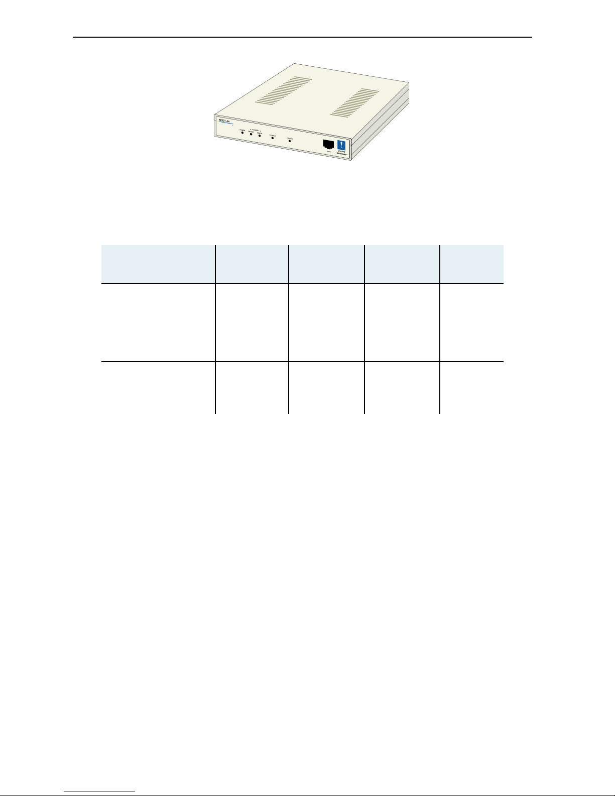
Figure 1. SP201-SA Chassis
Note: The cables you connect to the SP201-SA depend on the protocols. The following table lists the
ports and line each protocol uses in this guide’s standard installation.
A Physical Installation
1. Place the SP201-SA on a tabletop or shelf.
2. Connect the cables for one set of trunks to the ports on the rear of the SP201-SA chassis, as follows:
a For the CAS trunk (DTMF, R1, R2, or N5), do one of the following:
◆ For DTMF or R1, connect a T1 cable to the RJ48C port labeled Port 1.
or
◆ For R2 or N5, connect an E1 cable in one of the following ways:
- Connect an E1 cable to the RJ48C port labeled Port 1.
or
- Connect an E1 cable to the BNC Rx and Tx ports labeled Port 1.
b For the ISDN trunk, do one of the following:
◆ For ETSI ISDN on a two-port SP201-SA, connect an E1 cable to the RJ48C port labeled Port 2.
(For ETSI ISDN on a four-port SP201-SA, connect an E1 cable to the RJ48C port labeled Port 3.)
or
◆ For NI2 ISDN on a two-port SP201-SA, connect a T1 cable to the RJ48C port labeled Port 2.
(For NI2 ISDN on a four-port SP201-SA, connect a T1 cable to the RJ48C port labeled Port 3.)
Protocol Group Protocol
Port on
Two-Port
SP201-SA
Ports on
Four-Port
SP201-SA
Line
Channel-Associated
Signaling (CAS)
DTMF 1 1, 2 T1
R1 1 1, 2 T1
R2 1 1, 2 E1
ISDN ETSI ISDN 2 3, 4 E1
NI2 ISDN 2 3, 4 T1
Page 3

SP201-SA™ Installation Guide 3
Note: Channels on trunk 1 of the two-port SP201-SA map to channels on trunk 2, and vice versa.
In a standard installation of the four-port SP201-SA, channels on trunk 1 map to channels on trunk 3
(and vice versa), and channels on trunk 2 map to channels on trunk 4 (and vice versa).
3. If you are installing a four-port SP201-SA, connect another set of trunks to ports on the rear of the
chassis, as follows:
a For the CAS trunk (DTMF, R1, or R2), do one of the following:
◆ For DTMF or R1, connect a T1 cable to the RJ48C port labeled Port 2.
or
◆ For R2, connect an E1 cable to the RJ48C port labeled Port 2.
b For the ISDN trunk, do one of the following:
◆ For ETSI ISDN, connect an E1 cable to the RJ48C port labeled Port 4.
or
◆ For NI2 ISDN, connect a T1 cable to the RJ48C port labeled Port 4.
4. Connect the SP201-SA to its external power supply. Then connect the power supply to a power
source (a power outlet), and switch the power on.
Note: Shipments within North America include a power cable for connection to the power outlet.
For shipments outside North America, contact your distributor for a cable that meets local
requirements to connect the power supply to an outlet.
5. Connect an RJ45 cable from the RJ45 Supervisory port of the SP201-SA to the DB9 COM port of a
control terminal—for example, a PC. (An RJ45-to-DB9 adapter is included with the cable.)
6. On the control terminal, start a terminal emulation program, such as HyperTerminal. Configure the
serial communications for the control terminal as follows:
❖ When communication has been established, you should see the user> prompt.
7. If you don’t see a prompt, press Enter once.
❖ The user> prompt appears.
Note: After you have connected a local terminal to the SP201-SA device, you can connect a remote
terminal to the local terminal and manage the device from a remote location. See the document
Remote Access to SignalPath™ Devices.
Baud rate 9600 bps
Data bits 8
Parity None
Stop bit 1
Flow control None
Page 4

4 SP201-SA™ Installation Guide
B Port Configuration
What the terminal displays What you type What you are configuring
user> config lim
Interfaces for the
SP201-SA’s ports
List of Valid LIMs
1) 1 E1 120 Ohm/1 E1 120 Ohm
2) 2 T1 100 Ohm/1 E1 120 Ohm
3) 1 T1 100 Ohm/1 T1 100 Ohm
4) 2 T1 100 Ohm/2 T1 100 Ohm
5) 1 E1 120 Ohm/1 T1 100 Ohm
6) 1 E1 120 Ohm/2 T1 100 Ohm
7) 1 T1 100 Ohm/1 E1 75 Ohm
8) 1 T1 100 Ohm/1 E1 120 Ohm
9) 1 E1 75 Ohm/1 T1 100 Ohm
10) 1 E1 75 Ohm/1 E1 75 Ohm
> 11) 1 E1 75 Ohm/1 E1 120 Ohm <
12) 1 E1 120 Ohm/1 E1 75 Ohm
13) 2 T1 100 Ohm/2 E1 75 Ohm
14) 2 T1 100 Ohm/2 E1 120 Ohm
15) 2 E1 75 Ohm/2 T1 100 Ohm
16) 2 E1 75 Ohm/2 E1 75 Ohm
17) 2 E1 75 Ohm/2 E1 120 Ohm
18) 2 E1 120 Ohm/2 T1 100 Ohm
19) 2 E1 120 Ohm/2 E1 75 Ohm
20) 2 E1 120 Ohm/2 E1 120 Ohm
Enter LIM Choice fro m list above
[1-20] (current=11) ==>
Ports 1 and 2/Ports 3 and 4
Select the configuration that supports your SP201-SA’s port connections,
and press the Enter key. (The List of Valid LIMs shown is for a four-port
SP201-SA.)
Note: The standard choices shown below, in boldfaced numbers, include
120-ohm E1 interfaces. E1 interfaces may instead use 75 ohms over a BNC
connector. If you use BNC connectors, choose an appropriate combination
from the List of Valid LIMs above.
Protocol Conversion
Interfaces
DTMF–ETSI ISDN T1/E1
DTMF–NI2 ISDN T1/T1
R1–NI2 ISDN T1/T1
R2–ETSI ISDN E1/E1
R2–NI2 ISDN E1/T1
2-Port 4-Port
814
34
34
120
518
(A message similar to the following appears only if you
change the LIM configuration.)
LIM set to: 2 E1 120 Ohm/2 E1 120 Ohm
A coldstart is requi red for this
change to take effect
Do you wish to reset now (y/n)?
y (You must do this
now, so that
subsequent
configuration
parameters will
reflect the
SP201-SA’s port
configuration.)
Implementation of port
configuration
Page 5

SP201-SA™ Installation Guide 5
C Clocking Configuration
(Information on tests and restarts)
(Boot banner and
boot> prompt)
(Do not type
anything. The
application will load
in a few seconds.)
(Initializations)
(Application banner and
user> prompt)
(When you see the user>
prompt, the SP201-SA is
ready for further
configuration.)
What the terminal displays What you type What you are configuring
user> config clocks
Clocking (synchronization)
for the SP201-SA
Enter the trunk num ber [1-4] from
which this card is to derive its
clock source. Or en ter "0" if this
card is to use its internal clock.
The PRIMARY clock source is derived
from (current = INTERNALCLOCK): 1
Clock sourced from the device
connected to the remote end
of the R2 trunk
The SECONDAR Y clock source is d erived
from (current = INTERNALCLOCK): 0
Backup clock sourced from
the SP201-SA
user>
(Clocking has been
configured.)
What the terminal displays What you type What you are configuring
Page 6

6 SP201-SA™ Installation Guide
D Trunk Configuration
Perform the following procedure once for each trunk on the SP201-SA.
What the terminal displays What you type What you are configuring
user>
config framer
p
where p is the port
number (1, 2, 3,
or 4) Trunk on port p
WARNING: Configuring framers will
cause LOSS of calls! !!!!!!!
Do you wish to proceed anyway (Y/N) : y
For a T1 line:
LIM type: 2 T1 100 Ohm/2 E1 120 Ohm
1 D4 SF
2 D4 ESF
enter T1 frame type (currently
D4 SF):
For T1 lines: 1
or your T1 frame
type)
For an E1 line:
LIM type: 2 E1 120 Ohm/2 E1 120 Ohm
1 G704 CRC
2 G704 noCRC
3 G704 MF CRC
4 G704 MF noCRC
enter E1 frame type (currently
G704 MF no CRC):
For E1 lines: 3
(or your E1 frame
type) Frame type for trunk
For T1 lines:
line coding type choices are:
1 AMI
2 B8ZS
enter line coding type (currently
B8ZS) :
For T1 lines: 2
(or your T1 line
coding)
For E1 lines:
line coding type choices are:
1 AMI
2 HDB3
enter line coding type (currently
HDB3) :
For E1 lines: 2
(or your E1 line
coding)
Line coding for trunk
For T1 lines:
line length choices are:
1 0 to 115 feet
2 82 to 213 feet
3 180 to 312 feet
4 279 to 410 feet
5 377 to 509 feet
6 476 to 607 feet
7 574 to 689 feet
enter line length (curre ntly
0-115 feet):
1 (or your T1 cable
length)
T1 cable length
user >
(The trunk has been
configured.)
Page 7

SP201-SA™ Installation Guide 7
E Channel Configuration
See the following sections to configure the protocols in your SP201-SA:
E.1 Channel Configuration for DTMF Signaling
• DTMF signaling Section E.1, Channel Configuration for DTMF Signaling
• R1 signaling Section E.2, Channel Configuration for R1 Signaling
• R2 signaling Section E.3, Channel Configuration for R2 Signaling
• N5 signaling Section E.4, Channel Configuration for N5 Signaling
• ETSI ISDN signaling Section E.5, Channel Configuration for ETSI ISDN
• NI2 ISDN signaling Section E.6, Channel Configuration for NI2 ISDN
What the terminal displays What you type What you are configuring
user> config dt all
All DTMF channels
Set 1/1 thru 2/31 out-of-service?
(y or n) : <current=n> n
Placement of channels 1–31 of
trunk 1 and (on the four-port
SP201-SA) channels 1–31 of
trunk 2 into service
DTMF Caller ID/A NI used? (y or n) :
<current=n>
y (or n if caller ID is
not required)
Request for caller
identification
Other modifications? : (y or n) :
<current=n> n
Completion of standard
configuration for DTMF
signaling (If y
ou wish to
configure other parameters for
DTMF signaling, type y. Then
refer to the SP201-SA
Customization and Maintenance
Guide
.)
user>
(DTMF signaling has been
configured.)
Page 8

8 SP201-SA™ Installation Guide
E.2 Channel Configuration for R1 Signaling
What the terminal displays What you type What you are configuring
user> config r1 all
All R1 channels
Set 1/1 thru 2/31 out -of-service?
(y or n) : <curre nt= n> n
Placement of channels 1–31 of
trunk 1 and (on the four-port
SP201-SA) channels 1–31 of
trunk 2 into service
Template # for defau lt IAM ? :
(range 1 - 5) : <current=1> 1
Use of R1 IAM template 1
Template # for defau lt ACM ? :
(range 1 - 5) : <current=1 1
Use of R1 ACM template 1
Include Feature Group D (caller ID/
ANI)? (y or n) : <curren t=n>
y (or n if caller ID is
not required)
Request for caller
identification
(The following four questions appear only if you
answered y to the previous question.)
Use 911-Operato r Services Signali ng
(y or n) : <current=n> n
No use of 911 support
Max nbr of ANI digits to send R1 (0 =
all) ? : (range 0 - 32) : <current=0> 0 (zero)
Support for ANI of any size
Are Information digits supported? (y
or n) : <current=n> n
No support of Information
digits
Separate Wink required for B-Party
Number? (y or n) : <current=n> n
No separate wink for B-Party
Require wink at end of selection?
(y or n) : <current=n> n
No wink required at end of
selection
Generate ringback tone for R1
originated calls? (y or n) :
<current=n> n
No ringback generated for
caller
user>
(Standard configuration for
R1 signaling has been
completed. If y
ou wish to
configure other parameters for
R1 signaling, refer to the
SP201-SA Customization and
Maintenance Guide
.)
Page 9

SP201-SA™ Installation Guide 9
E.3 Channel Configuration for R2 Signaling
What the terminal displays What you type What you are configuring
user> config r2 all
All R2 channels
Set 1/1 thru 2/31 out- of-service?
(y or n) : <current=n> n
Placement of channels 1–31 of
trunk 1 and (on the four-port
SP201-SA) channels 1–31 of
trunk 2 into service
Select R2 converter mode :
< 1> CCITT <14>Israel
< 2> Argentina <15>Korea
< 3> Brazil <16>Kuwait
< 4> Brazil-Emb <17>Malaysia
< 5> Chile <18>Mexico
< 6> China <19>New Zeala nd
< 7> Columbia <20>Paraguay
< 8> Columbia-Bts <21>Philippines
< 9> Columbia-Ngt <22>Singapore
<10> Costa Rica <23>Thailand
<11> Ecuador <24>Uruguay
<12> Greece <25>Venezuela
<13> Indonesia
Outgoing R2 converter mode? (1-25;
current=CCITT) :
1 (or your country
code)
The country code for the
version of R2 signaling this
SP201-SA will use
Request R2 caller ID? (y or n) :
<current=n>
y (or n if caller ID is
not required)
Request for caller
identification
Send I15 to R2 side at end of a ddress
(vs timeout)? (y or n) : <current=y>
y (or n, depending
on your requirement)
Sending an Address
Complete code (An answer of
n causes the adjacent switch
to wait for the appropriate
timer to expire before
processing the call.)
Other modifica tions? : (y or n) :
<current=n> n
Completion of standard
configuration for R2 signaling
(If y
ou wish to configure other
parameters for R2 signaling,
type y. Then refer to the
SP201-SA Customization and
Maintenance Guide
.)
user>
(R2 signaling has been
configured.)
Page 10

10 SP201-SA™ Installation Guide
E.4 Channel Configuration for N5 Signaling
What the terminal displays What you type What you are configuring
user> config n5 all
All N5 channels
Set 1/1 thru 2/31 out- of-service?
(y or n) : <curren t= n> n
Placement of channels 1–31 of
trunk 1 and (on the four-port
SP201-SA) channels 1–31 of
trunk 2 into service
Destination country code for calls to
N5 (current) :
Enter up to 3 digits: (your country code)
Your country’s international
dialing code
Transit calls to N5 enabled ? (y or
n) : <current=n> n
Disallowance of transit traffic
Use Calling Pa rty Ca tego ry to set N5
language digit? (y or n) :
<current=n> n
No use of the calling party
category to derive the
language digit
N5 side outgoing language digit
(current) :
Enter up to 1 digits:
(Press Enter to leave
this field empty.)
The fixed language digit for
calls originating from the N5
side
Prefix to be strippe d from digits
before sending to N5 (current) :
Enter up to 3 digits:
(Press Enter to leave
this field empty.)
Digits to remove from the
front of the country code
Digits that cause C1 1 to be sent to
N5 (current) :
Enter up to 18 digits:
(Press Enter to leave
this field empty.)
Digit string that causes the
C11 operator code to be sent
to N5
Digits that cause C1 2 to be sent to
N5 (current) :
Enter up to 18 digits:
(Press Enter to leave
this field empty.)
Digit string that causes the
C12 operator code to be sent
to N5
Language digit expected from N5 [* =
any] (current) :
Enter up to 1 digits:
(Press Enter to leave
this field empty.)
Acceptance of calls only with
a specific language digit (if
entered)
Transit calls FROM N5 enabled ? (y or
n) : <current=n> n
Rejection of transit calls (by
returning a busy flash)
Digits to prepend in non-transit
calls coming from N5 (current) :
Enter up to 3 digits:
(Press Enter to leave
this field empty.)
Digits to prepend to nontransit calls
Use calling party ca tegory from
template ? (y or n) : <cur rent=n> n
Derivation of the Calling
Party Category from the N5
language digit
Digits to send when C1 1 is received
from N5 (current) :
Enter up to 18 digits:
(Press Enter to leave
this field empty.)
The digit string to send when
the C11 operator code is
received from N5
Digits to send when C1 2 is received
from N5 (current) :
Enter up to 18 digits:
(Press Enter to leave
this field empty.)
The digit string to send when
the C12 operator code is
received from N5
Page 11

SP201-SA™ Installation Guide 11
Template # for default IAM ? : (range
1 - 5) : <current=1> 1
Default values for IAM
parameters required on the
SS7 side but not specified by
the N5 protocol
Template # for default ACM ? : (range
1 - 5) : <current=1> 1
Default values for ACM
parameters required on the
SS7 side but not specified by
the N5 protocol
Use user-defined caller ID (ANI) in
calls from N5? (y or n) : <current=n> n
No support of caller ID (ANI).
Note: Although N5 does
not use ANI, some
networks require ANI in
all calls. Answering y here
places a fixed ANI in each
call originating from N5.
Generate ringback tone for N5
originated calls? (y or n) :
<current=n> n
No ringback generation by
SignalPath for calls from N5
device
user>
(This completes standard
configuration of N5 signaling.
If you wish to customize the
configuration of N5 signaling,
refer to the SP201-SA
Customization and Maintenance
Guide.)
What the terminal displays What you type What you are configuring
Page 12

12 SP201-SA™ Installation Guide
E.5 Channel Configuration for ETSI ISDN
In the two-port SP201-SA, perform the following procedure once for trunk 2. In the four-port SP201-SA,
perform the procedure once each for trunks 3 and 4.
Note: If you are performing this procedure on a two-port SP201-SA, read trunk 3 as trunk 2.
What the terminal displays What you type What you are configuring
user> config dchans
ISDN signaling channel
The following is the present Trunk
configuration.
If a change to the Timeslot or
Interface Type is de sired
Enter the Trunk number you wish to
modify or exit:
Trunk Signaling Timeslot Trunk Link Interface Protocol
Type Type State Type
------------------------------------------------------------------------3 D 16 E1 Inactive Network ETSI ISDN
4 D 16 E1 Inactive Network ETSI ISDN
ISDN Trunk Number
Enter value(3 - 4) or "exit" :
p
where p is the port
number (3 or 4) ISDN trunk p
Select interfac e type - user(0) or
network(1) : <curr ent=1> 1 (or 0)
SP201-SA as the Network role
(or as the User role) in this
ISDN connection
ISDN Interface num ber 1 assigned to
Trunk
p
,
with a D Channel on time slot 16.
Change ISDN Signal ing Channel
Enter value(1 - 31; current="16") or
"exit" : 16
Signaling timeslot
(The following message appears only if you change
the channel number used as the signaling timeslot.)
Changes applied
The card must be reset for the
changes to operate properly
Do you wish to reset now (y/n)?
n
Delay in implementation of
changes until performing a
warmstart (described in
Section F, SP201-SA
Warmstart)
not resetting.. .
user>
(ISDN signaling has been
configured on this trunk.)
Page 13

SP201-SA™ Installation Guide 13
E.6 Channel Configuration for NI2 ISDN
In the two-port SP201-SA, perform the following procedure once for trunk 2. In the four-port SP201-SA,
perform the procedure once each for trunks 3 and 4.
Note: If you are performing this procedure on a two-port SP201-SA, read trunk 3 as trunk 2.
What the terminal displays What you type What you are configuring
user> config dchans
ISDN signaling channel
The following is th e present Trunk
configuration.
If a change to the Time slot or
Interface Type is desired
Enter the Trunk num ber you wish to
modify or exit:
Trunk Signaling Timesl ot Trunk Link Interface Protocol
Type Type State Type
------------------------------------------------------------------------3 D 24 T1 Inactive Network NI2 ISDN
4 D 24 T1 Inactive Network NI2 ISDN
ISDN Trunk Number
Enter value(3 - 4) or "exit" :
p
where p is the port
number (3 or 4) ISDN trunk p
Select interface type - user(0) or
network(1) : <current=1> 1 (or 0)
SP201-SA as the Network role
(or as the User role) in this
ISDN connection
ISDN Interface number 1 assigned to
Trunk
p
,
with a D Channel on timeslot 24.
Change ISDN Signaling Channel
Enter value(1 - 31; current="24") or
"exit" : 24
Signaling timeslot
(The following message appears only if you change
the channel number used as the signaling timeslot.)
Changes applie d
The card must be rese t for the
changes to operat e properly
Do you wish to reset no w (y/n)?
n
Delay in implementation of
changes until performing a
warmstart (described in
Section F, SP201-SA
Warmstart)
not resetting...
user>
(ISDN signaling has been
configured on this trunk.)
Page 14

14 SP201-SA™ Installation Guide
F SP201-SA Warmstart
This completes the standard installation. To configure other parameters, see the SP201-SA Customization
and Maintenance Guide. For hardware specifications, see the SP201-SA Hardware Reference Guide.
What the terminal displays What you type What you are configuring
user> warmstart
Implementation of the ISDN
configuration
This action will drop any calls that
are in progress.
Do you really want to continue?
(y/n): y
(Information on tests and restarts)
(Boot banner)
boot>
(Do not type anything.
The application will
load in a few seconds.)
(Initializations)
(Application banner)
user>
(When you see the user>
prompt, the SP201-SA is
ready for use.)
 Loading...