

Page 1

ER52FX730V
ER52FX730VCA
OPERATORS MANUAL
Page 2

ENCORE MANUFACTURING
A DIVISION OF WORLDLAWN POWER EQUIPMENT, INC.
ENCOREEQUIPMENT.COM
2415 ASHLAND AVE
BEATRICE, NE 68310
800-267-4255
FAX – 402-223-4103
2
Page 3

Contents
SAFETY ................................................................................................................................................................................ 6
Safety Alert Symbol ............................................................................................................................................................. 6
TRAINING ............................................................................................................................................................................ 6
PREPARATION ..................................................................................................................................................................... 6
OPERATION ......................................................................................................................................................................... 7
SLOPE OPERATION .............................................................................................................................................................. 9
MAINTENANCE AND STORAGE ......................................................................................................................................... 10
SAFETY AND INSTRUCTIONAL DECALS .............................................................................................................................. 12
SPECIFICATIONS ............................................................................................................................................................ 14
MODEL NUMBER ............................................................................................................................................................... 14
ENGINE .............................................................................................................................................................................. 14
FUEL SYSTEM ..................................................................................................................................................................... 14
ELECTRICAL SYSTEM .......................................................................................................................................................... 14
TRANSMISSION ................................................................................................................................................................. 14
CUTTING DECK .................................................................................................................................................................. 14
OPERATION ...................................................................................................................................................................... 15
OPERATOR CONTROLS ...................................................................................................................................................... 15
SAFETY INTERLOCK ........................................................................................................................................................ 15
CHOKE CONTROL ........................................................................................................................................................... 15
THROTTLE CONTROL ..................................................................................................................................................... 15
PARK BRAKE LEVER ....................................................................................................................................................... 15
IGNITION SWITCH ......................................................................................................................................................... 15
HOUR METER ................................................................................................................................................................ 15
DRIVE WHEEL RELEASE VALVES .................................................................................................................................... 16
BLADE ENGAGEMENT SWITCH ...................................................................................................................................... 16
PRE-START ....................................................................................................................................................................... 16
OPERATING INSTRUCTIONS ...................................................................................................................................... 17
STARTING THE ENGINE.................................................................................................................................................. 17
BLADE ENGAGEMENT ................................................................................................................................................... 17
DISENGAGING THE BLADES ........................................................................................................................................... 18
STOPPING THE ENGINE ................................................................................................................................................. 18
3
Page 4

DRIVING THE MACHINE................................................................................................................................................. 18
DRIVING FORWARD ....................................................................................................................................................... 18
DRIVING IN REVERSE ..................................................................................................................................................... 18
OPERATING THE PLATFORM ......................................................................................................................................... 18
OPERATING THE MACHINE WITH THE PLATFORM UP .................................................................................................. 19
OPERATING THE MACHINE WITH THE PLATFORM DOWN ........................................................................................... 19
ADJUSTING THE CUTTING HEIGHT ................................................................................................................................ 19
TRANSPORTING .................................................................................................................................................................... 20
TRANSPORTING A UNIT ................................................................................................................................................. 20
LOADING A UNIT ........................................................................................................................................................... 20
MAINTENANCE ................................................................................................................................................................ 21
RECOMMENDED MAINTENANCE SCHEDULE(S) ............................................................................................. 22
CHECK ENGINE OIL LEVEL .............................................................................................................................................. 23
CHECK BATTERY CHARGE .............................................................................................................................................. 23
RECOMMENDED JUMP STARTING PROCEDURE ........................................................................................................... 23
RELEASE THE CUSHION FOR REAR ACCESS ................................................................................................................... 24
CHECK MOWER BLADES ................................................................................................................................................ 24
CHECK SAFETY INTERLOCK SYSTEM .............................................................................................................................. 25
CHECK FOR LOOSE HARDWARE .................................................................................................................................... 26
SERVICE AIR CLEANER ................................................................................................................................................... 26
CHANGE ENGINE OIL ..................................................................................................................................................... 26
CHANGE ENGINE OIL FILTER ......................................................................................................................................... 26
CHECK HYDRAULIC OIL LEVEL ........................................................................................................................................ 27
CHECK TIRE PRESSURES ................................................................................................................................................. 27
CHECK CONDITION OF BELTS ........................................................................................................................................ 27
LUBRICATE GREASE FITTINGS ....................................................................................................................................... 27
CHECK SPARK PLUGS ..................................................................................................................................................... 27
CHANGE HYDRAULIC SYSTEM FILTER AND FLUID ......................................................................................................... 27
HYDRAULIC SYSTEM AIR PURGE.................................................................................................................................... 28
WHEEL HUB NUT TORQUE SPECIFICATION ................................................................................................................... 28
THREAD LOCKING ADHESIVES ....................................................................................................................................... 29
COPPER-BASED ANTI-SEIZE ........................................................................................................................................... 29
4
Page 5

ADJUSTMENTS ................................................................................................................................................................ 29
DECK LEVELING ............................................................................................................................................................. 29
PUMP DRIVE BELT TENSION .......................................................................................................................................... 30
MOWER DECK DRIVE BELT TENSION............................................................................................................................. 30
PARK BRAKE ADJUSTMENT ........................................................................................................................................... 30
FORWARD TRACKING ADJUSTMENT ............................................................................................................................. 30
NEUTRAL ADJUSTMENT ................................................................................................................................................ 30
CASTER PIVOT BEARINGS PRE-LOAD ADJUSTMENT...................................................................................................... 30
CLEANING ......................................................................................................................................................................... 31
CLEAN ALL DEBRIS FROM ENGINE AND EXHAUST SYSTEM AREA. ................................................................................ 31
CLEAN DUST AND DIRT FROM CYLINDER HEAD FINS.................................................................................................... 31
CLEAN DEBRIS FROM MACHINE .................................................................................................................................... 31
CLEAN GRASS BUILD-UP UNDER DECK .......................................................................................................................... 31
TROUBLESHOOTING ..................................................................................................................................................... 32
WIRING SCHEMATICS ................................................................................................................................................... 33
HYDRAULIC SCHEMATIC ............................................................................................................................................. 34
Evaporative Emission Control Warranty Statement ...................................................................................................... 35
Limited Warranty: .............................................................................................................................................................. 37
5
Page 6
TRAINING
SAFETY
Safety Alert Symbol
This symbol means: ATTENTION! BECOME
ALERT! YOUR SAFETY IS INVOLVED!
The safety alert symbol appears above information
which alerts you to unsafe actions or situations and
will be followed by the word DANGER,
WARNING, or CAUTION.
DANGER: White lettering/Red background.
Indicates failure to observe the safety instructions
will result in death or serious injury.
WARNING: Black letters on orange
background.
Read the instructions carefully. Become
familiar with the safe operation of the
equipment, operator controls, and safety signs.
All operators need to be trained before
operating this unit.
Never let children or untrained people operate
the equipment without proper instruction.
Keep everyone, especially children and pets,
away from the area of operation. Remember
that the operator or user is responsible for
accidents or hazards occurring to other people
or their property.
PREPARATION
Evaluate the terrain to determine what
accessories and attachments are needed to
properly and safely perform the job. Use only
accessories and attachments approved by
ENCORE
The use of personal protective equipment, such
as (but not limited to) safety glasses, hearing
protection, substantial footwear and long
trousers is highly recommended.
Indicates failure to observe safety instructions could
result in death or serious injury.
CAUTION: Black letters on yellow
background.
Indicates failure to observe the safety instructions
may result in death or serious injury.
CAUTION
This machine produces sound levels in excess
of 85 dBA at the operator’s ear and can cause
hearing loss through extended periods of
exposure.
Wear hearing protection when operating this
machine.
Thoroughly inspect the area where the
equipment is to be used and remove all stones,
sticks, wires, bones, and other foreign objects
which may damage the equipment or cause
personal injury to operator or bystanders.
Check that the operator’s presence controls,
safety switches, and shields are attached and
6
Page 7

functioning properly. Do Not operate unless
they function properly.
In certain conditions during fueling, static
electricity can be released causing gasoline
vapors to ignite.
DANGER
In certain conditions gasoline is extremely
flammable and highly explosive.
A fire or explosion from gasoline can burn you,
others and cause property damage.
Refuel outdoors, on level ground while engine
is cold.
Never remove fuel cap or add fuel when engine
is running or when engine is hot.
Never fill the fuel tank so that gasoline level
rises above the bottom of the filler neck to allow
for gasoline expansion and prevent fuel
spillage.
If fuel is spilled, DO NOT attempt to start the
engine. Move away from the area of the spill
and avoid creating any source of ignition until
fuel vapors have dissipated.
Do not smoke while refueling and stay away
from an open flame or where gasoline fumes
may be ignited by spark.
Do not operate without entire exhaust system in
place and in proper working condition.
Do not place any equipment that is leaking
gasoline in an enclosed trailer.
Be sure all fuel tanks and gasoline storage
containers have proper caps installed to
prevent spillage and minimize vapor escaping
into the trailer.
DANGER
A fire or explosion from gasoline can burn you,
others, and cause property damage.
Purchase and store gasoline only in an
approved container
Always place gasoline containers on the ground
away from your vehicle while filling.
Do not fill gasoline containers inside a vehicle
or on a truck or trailer bed because interior
carpets or plastic truck bed liners may insulate
the container and slow the loss of any static
charge.
When practical, remove gas powered
equipment from the truck or trailer and refuel
the equipment with its wheels on the ground.
If this is not possible, then refuel such
equipment on a truck or trailer from a portable
container, rather than from a gasoline dispenser
nozzle.
If a gasoline dispenser nozzle must be used,
keep the nozzle in contact with rim of the fuel
tank or container opening at all times until
fueling is complete.
WARNING
Gasoline is harmful or fatal if swallowed. Longterm exposure to vapors and failure to use
caution may cause serious injury or illness.
Avoid prolonged breathing of vapors.
Keep face away from nozzle and gas
tank/container opening.
Keep away from eyes and skin.
Never siphon by mouth.
OPERATION
Although hazard control and accident prevention
are partially dependent upon the design and
configuration of the equipment, these factors are
7
Page 8

also dependent upon the awareness, concern and
proper training of the personnel involved in the
operation, transport, maintenance and the storage
of the equipment. It is essential that all Operator
Safety Mechanisms be connected and in operating
condition prior to use for mowing.
WARNING
Operating engine parts, especially the muffler,
become extremely hot. Severe burns can occur
on contact and debris, such as leaves, grass,
brush, etc. can catch fire.
Allow engine parts, especially the muffler, to
cool before touching.
Remove accumulated debris from muffler
and engine area.
Park machine on level ground. Stop engine,
wait for all moving parts to stop, remove key
and engage parking brake:
o Before checking, cleaning or working on
the mower.
o After striking a foreign object or machine
develops an abnormal vibration (inspect
machine for damage and repair before
resuming operation)
o Before clearing blockages
o Before leaving the operator position
Never mow with the discharge deflector raised,
removed or altered unless there is a grass
collection system or mulch kit in place and
working properly.
Do Not change the engine governor setting or
overspeed the engine.
WARNING
Engine exhaust contains carbon monoxide,
which is an odorless deadly poison that can kill
you.
Do Not run engine indoors or in a small
confined area where dangerous carbon
monoxide fumes can collect.
Operate only in daylight or good artificial light,
keeping away from holes and hidden hazards.
Be sure all drives are in neutral and parking
brake is engaged before starting engine.
Never raise deck with blades running.
Never operate the mower with damaged
guards, shields, or covers. Always have safety
shields, guards, switches and other devices in
place and in proper working condition.
Stop engine, wait for all moving parts to stop
and engage parking brake:
o Before refueling
o Before dumping the grass catcher
o Before making height adjustments
8
Page 9

WARNING
Hands, feet, hair, clothing, or accessories can
become entangled in rotating parts. Contact
with rotating parts can cause traumatic
amputation or severe lacerations.
Do Not operate the machine without guards,
shields, and safety devices in place and
working properly.
Keep hands, feet, hair, jewelry, or clothing away
from rotating parts.
DO NOT operate the mower when people,
especially children, or pets are in the area.
Stop the blades, slow down, and use caution
when transporting the mower to and from the
area to be mowed or crossing surfaces other
than grass.
Do not operate the mower under the influence
of alcohol or drugs.
Be alert, slow down and use caution when
making turns. Look behind and to the side
before changing directions.
Use extreme care when loading and unloading
the machine into a trailer or truck.
Be aware of the mower discharge path and
direct discharge away from others.
Use care when approaching blind corners,
shrubs, trees, or other objects that may obscure
vision.
SLOPE OPERATION
Use extreme caution when mowing and/or turning
on slopes as loss of traction and/or tip-over could
occur. The operator is responsible for the safe
operation on slopes.
DANGER
Mowing on wet grass or steep slopes can cause
sliding and loss of control.
When mowing ditches or slopes recommended
practice is to latch operator platform in the up
position and continue to use mower in the true
walk behind mode.
Mow across slopes, never up and down.
Do Not mow slopes when grass is wet.
Do Not mow near drop-offs or near water.
Do Not mow slopes greater than 15 degrees.
Reduce speed and use extreme caution on
slopes.
Avoid sudden turns or rapid speed changes.
Remove or mark obstacles such as rocks, tree
limbs, etc. from the mowing area. Tall grass
can hide obstacles.
Be aware that operating on wet grass, across
steep slopes or downhill may cause the mower
to lose traction. Loss of traction to the drive
wheels may result in sliding and a loss of
braking and steering.
Watch for ditches, holes, rocks, dips and rises
that change the operating angle, as rough
terrain could overturn the machine.
Always avoid sudden starting or stopping on a
slope. If tires lose traction, disengage the
blades and proceed slowly off the slope.
Use extreme care with grass catchers or
attachments. These can change the stability of
the machine and cause loss of control.
9
Page 10

MAINTENANCE AND STORAGE
Before any maintenance, disengage drives,
lower implement, set parking brake, stop engine
and remove key or disconnect spark plug wire.
Wait for all moving parts to stop before
adjusting, cleaning or repairing.
Park machine on level ground. Never allow
untrained personnel to service machine
For engine maintenance, follow the engine
manufacture’s recommendations as stated in
the engine manual.
Keep engine, engine area, free from
accumulation of grass, leaves, excessive
grease, or oil and other debris. These materials
can become combustible and may result in a
fire.
Maximum mowing results and safety can only
be achieved if the mower is properly maintained
and operated correctly.
Check all bolts frequently to maintain proper
tightness.
Keep all guards, shields and safety devices in
place and in safe working condition.
All replacement parts must be the same as, or
equivalent to, the parts supplied on original
equipment.
Use care when checking blades. Wrap the
blade(s) or wear gloves, and use caution when
servicing them. Only REPLACE damaged
blades, NEVER straighten or weld them.
Disconnect the battery cable from the negative
battery post when the unit will be allowed to sit
for more than 30 days without use.
Store fuel in a container specifically designed
for this purpose in a cool, dry place.
Gasoline powered equipment or fuel containers
should not be stored in a basement or any
enclosed area where open pilot lights or heat
appliances are present.
Shut off fuel while storing or transporting. Do
not store fuel near flames or drain indoors.
DANGER
Charging or jump starting the battery may
produce explosive gasses. Battery gases
can explode causing serious injury.
Keep sparks, flames, or cigarettes away
from battery.
Ventilate when charging or using battery
in an enclosed space.
Make sure venting path of battery is
always open once battery is filled with
acid
Always shield eyes and face from
battery.
DANGER
Battery electrolyte contains sulfuric acid,
which is poisonous and can cause severe
burns. Swallowing electrolyte can be fatal
or if it touches skin can cause severe
burns.
Wear safety glasses to shield eyes, and
rubber gloves to protect skin and
clothing when handling electrolyte.
Do Not swallow electrolyte.
In the event of an accident, flush with
water and seek medical attention
immediately.
10
Page 11

Hydraulic fluid escaping under pressure can
CAUTION
If the ignition is in the “ON” position there
is potential for sparks and engagement of
components. Sparks could cause an
penetrate skin and cause injury. Fluid
accidentally injected into the skin must be
surgically removed within a few hours by a
doctor familiar with this form of injury or
gangrene may result.
explosion or moving parts could engage
causing personal injury.
Be sure ignition switch is in the “OFF”
position before charging the battery.
WARNING
Removing standard, original equipment
parts and accessories may alter the
warranty, traction, and safety of the
machine. Unauthorized changes to the
engine, fuel or venting system, may violate
EPA and CARB regulations.
Make sure all hydraulic fluid hoses and lines
are in good condition and all hydraulic
connections and fitting are tight before
applying pressure to hydraulic system.
Keep body and hands away from pinhole
leaks or nozzles that high pressure
hydraulic fluid.
Use cardboard or paper, not your hands, to
find hydraulic leaks.
Safely relieve all pressure in the hydraulic
system by placing the motion control levers
in neutral and shutting off the engine before
performing any work on the hydraulic
system.
WARNING
11
Page 12
SAFETY AND INSTRUCTIONAL
DECALS
Keep all safety signs legible. Remove all
grease, dirt and debris from safety signs
and instructional labels.
Replace all worn, damaged, or missing
safety signs.
When replacement components are
installed, be sure that current safety signs
are affixed to the replaced components.
If an attachment or accessory has been
installed, make sure current safety signs
are visible.
New safety signs may be obtained from
your authorized Encore equipment dealer.
Safety signs may be affixed by peeling off
the backing to expose the adhesive
surface. Apply only to a clean, dry surface.
Smooth to remove any air bubbles.
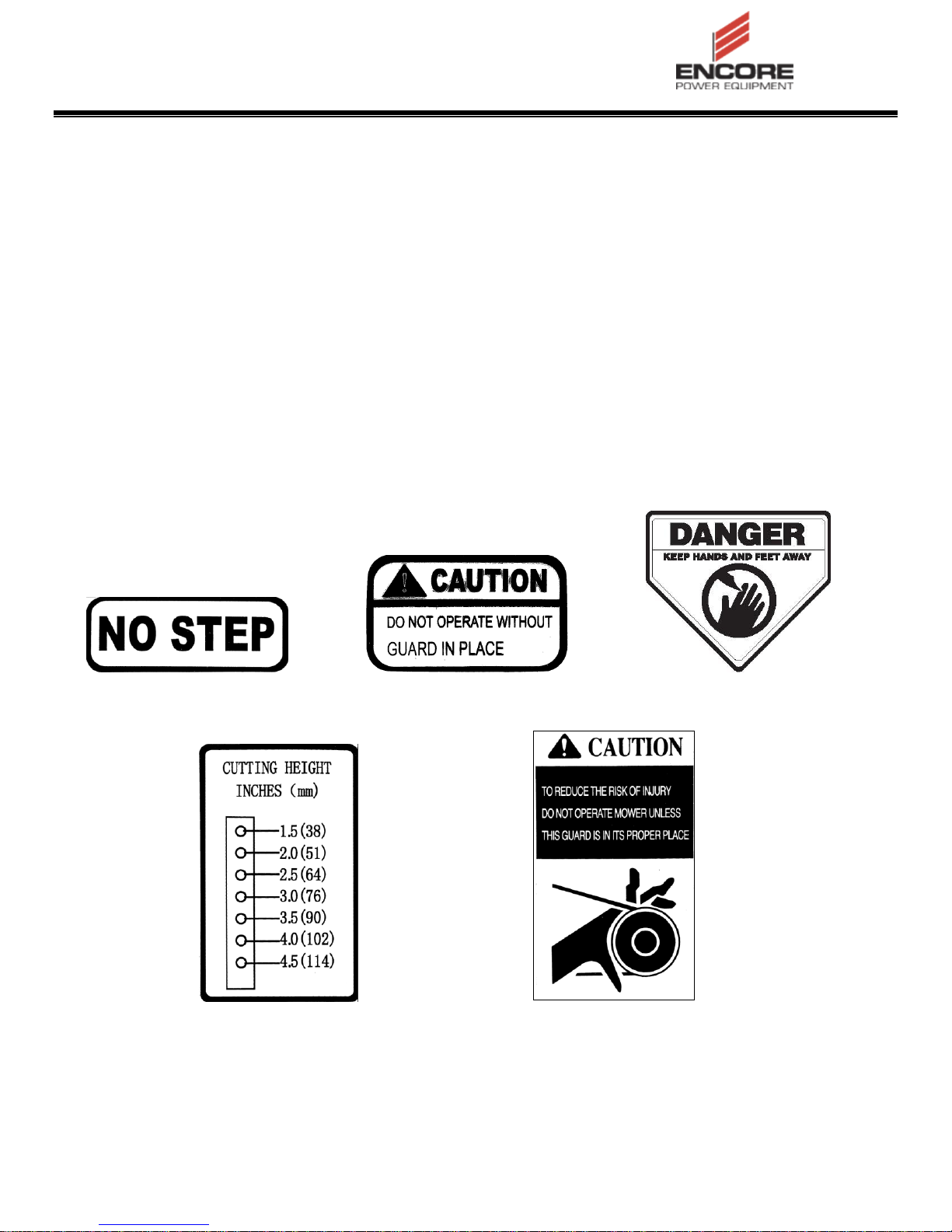
Familiarize yourself with the following safety
signs and instructional labels. They are
critical to the safe operation of your
machine.
8304 8303 363023
8406 8008
12
Page 13

CONSOLE DECAL – 453363
CLUTCH ON CLUTCH OFF FAST SLOW
CONSOLE GRAPHICS
NEUTRAL REVERSE PARK BRAKE CHOKE
13
Page 14

TRANSMISSION
Two Hydro Gear® variable displacement
SPECIFICATIONS
MODEL NUMBER
pumps with two, Parker® Wheel Drive
motors
Hydraulic Oil: 15w-50 Synthetic
Speed: 0-8.0 mph Fwd
0-5.0 mph Reverse
ER52FX730V
ER52FX730VCA
WEIGHT & DIMENSIONS
Length: 72”
62” w/Platform up
Width: 72”
65” w/Deflector up
Wheel Base: 33”
Wheel Track-Front: 36”
Wheel Track-Rear: 44”
Weight: 750 Lbs
ENGINE
Kawasaki FX730V
See your Engine Owner’s Manual
RPM: High Idle: 3600
Low Idle: 1550
FUEL SYSTEM
Capacity: 5 Gal
Type of Fuel: Regular Unleaded Gasoline
87 Octane or higher
Fuel Filter: In-line
CUTTING DECK
Cutting Width: 52”
Discharge: Side
Blade Size: 18” (3 ea)
Deck Drive: Electric Clutch
Deck: 7 ga Welded Steel Floating Deck
Deck Depth: 5”
Cutting Height 1.5” to 4.5”Adjustment:
Mulching Kit: Optional
TIRES
o Front: 11 x 5.00-4 Smooth
o Pressure 12-14 psi (83-97 kPa)
o Rear: 18 x 9.5-8 Turf
o Pressure 15 psi (103 kPa)
ELECTRICAL SYSTEM
Charging System: 12 Volt, 15 Amp @
3600 RPM
Battery Type: Group Ul
Battery Class: 350 CCA Minimum
Battery Voltage:12V DC
Polarity: Neg. Ground
Fuses: (1) 15A; (1) 20A
14
Page 15

PARK BRAKE LEVER
OPERATION
Located on right side of unit
To engage the brake, pull the lever rearward.
OPERATOR CONTROLS
Steering and Motion Control:
The motion control levers control the forward
and reverse rotation of the respective tire.
Speed is proportional to amount the levers are
moved; moving the levers to the center (neutral)
position brakes the movement of the machine.
SAFETY INTERLOCK
TO START: Control levers must be in NEUTRAL
position, park brake must be ON, and blade switch
must be OFF IN ORDER TO START.
TO RUN: One control lever must be in IN position
to remove park brake or engine will stop.
TO LEAVE OPERATOR POSITION: Park brake must
be set to ON before both control handles are
returned to NEUTRAL, AND blade switch must be
OFF in order to leave operator position.
CHOKE CONTROL
Located on the control console
To release, push the lever forward.
When parking on a steep slope, the wheels
must be chocked or blocked in addition to the
brake being engaged. The unit must be tied
down and brake engaged when transporting.
Park brake must be disengaged before moving.
IGNITION SWITCH
Located on the control console.
The ignition switch is used to start and stop the
engine. The switch has three positions “OFF”,
“ON” and “START”. Insert key into switch and
rotate clockwise to the “ON” position. Rotate
clockwise to the next position to engage the
starter (key must be held against spring
pressure in this position). Allow the key to
return to the “ON” position immediately after the
engine starts.
NOTE: To start the engine, the control levers
must be in the neutral positions, park brake
must be on, and blade switch must be off.
The choke is used to aid in starting a cold
engine. Pulling the choke knob up will move
the choke into the “on” position, pushing the
choke down will return the choke to the “off”
position.
THROTTLE CONTROL
Located on the control console
The throttle is used to control engine speed.
Moving the throttle lever forward will increase
engine speed and moving the throttle lever to
the rear will decrease engine speed. Moving
the throttle forward into the detent is full throttle.
HOUR METER
Located on the control console
The hour meter records the number of hours
that the engine has run.
15
Page 16

DRIVE WHEEL RELEASE VALVES
Located on the right front corner of the
hydrostatic pumps.
Drive wheel release valves are used to release
the hydrostatic drive system to allow the
machine to be moved by hand without the
engine running.
With a 5/8 wrench, turn both valves one turn
counterclockwise to release the drive system.
Turn clockwise to reset the drive system. Do
Not overtighten. Do Not tow machine.
PRE-START
Fill fuel tank on level ground. For best results
use only clean, fresh regular grade unleaded
gasoline with an octane rating of 87 or higher.
IMPORTANT: Never use methanol, gasoline
containing methanol, gasohol containing
more than 10% ethanol, premium gasoline,
or white gas because the fuel system could
be damaged.
Do Not add oil to gasoline
BLADE ENGAGEMENT SWITCH
Located on console
Switch must be pulled out (up) to engage the
blades. Switch is pushed in to disengage the
blades.
Do Not over fill fuel tank. Fill the fuel tank to
the bottom of the filler neck. The empty space
in the tank allows gasoline to expand.
Overfilling may result in fuel leakage or damage
to the engine or emission system.
Make sure you understand the controls, their
locations, their functions, and their safety
requirements.
Refer to the Maintenance section and perform
all the necessary inspection and maintenance
steps.
16
Page 17

OPERATING
BLADE ENGAGEMENT
INSTRUCTIONS
STARTING THE ENGINE
1. Move both control levers to the neutral
position.
2. Pull the parking brake lever rearward to
engage the parking brake.
3. Push in (down) on the PTO switch to the
“disengage” position.
4. Place the throttle midway between the
“SLOW” and “FAST” positions.
5. On a cold engine, pull the choke lever up
into the “ON” position.
On a warm engine, leave the choke in the
“OFF” position.
6. Turn ignition switch to the “START” position.
Release the switch as soon as the engine
starts.
IMPORTANT: Do Not crank the engine
continuously for more than ten seconds
at a time. If the engine does not start,
allow a 60 second cool-down period
between starting attempts. Failure to
follow these guidelines can burn out the
starter motor.
7. If the choke is in the “ON” position,
gradually return choke to the “OFF”
position as the engine warms up.
DANGER
The rotating blades under the mower deck
are dangerous. Blade contact can cause
serious injury or kill you.
Do Not put hands or feet under the mower
or mower deck when the blades are
engaged.
DANGER
An uncovered discharge opening will allow
objects to be thrown in an operator’s or
bystander’s direction. Also, contact with
the blade could occur. Thrown objects or
blade contact can cause serious injury or
death.
Never operate the mower with the discharge
deflector raised, removed, or altered unless
there is a grass collection system or mulch
kit in place and working properly.
The PTO switch engages the cutting blades.
Be sure all persons are clear of mower deck
and discharge area before engaging the PTO.
1. Set throttle to “MIDWAY” position.
2. Move either motion control lever to the
center, operate position
3. Continue holding the motion control lever in
the center, operate position and pull up on
the blade control switch (PTO). The clutch
should engage and the mower blades begin
rotating.
4. Place the throttle in the “FAST” position to
begin mowing.
5. Disengage park brake before operating
machine.
17
Page 18

DISENGAGING THE BLADES
1. Set the throttle midway between the
“SLOW” and “FAST” positions.
2. Push down on the PTO switch to disengage
the blades.
STOPPING THE ENGINE
1. Bring the unit to a full stop.
2. Move the motion control levers to the
neutral position; move the control levers
out to the neutral position.
3. Engage the parking brake.
4. Push down on the PTO switch to
disengage the blades.
5. Place the throttle midway between the
“SLOW” and “FAST” positions.
6. Turn the ignition switch to the “OFF”
position to stop the engine.
7. Remove the key to prevent children or
other unauthorized persons from
starting engine.
DRIVING THE MACHINE
CAUTION
DRIVING FORWARD
1. Move one motion control lever into the
neutral operate position.
2. Release the parking brake.
3. Move the other motion control lever to
neutral operate position.
4. To move forward in a straight line, move
both levers forward with equal pressure.
To turn left or right, pull the motion control lever
back toward neutral in the desired turn
direction.
The machine will move faster the farther the
motion control levers are moved from the
neutral position.
5. To stop, position both motion control levers
in the neutral operate position.
DRIVING IN REVERSE
1. Move the motion control levers to the
neutral operate position.
2. To move rearward in a straight line, slowly
move both levers rearward with equal
pressure.
Erratic movement of the control levers may
cause the Operator to lose control of the
machine, which may cause damage to the
machine or injury.
Use slow and steady movement of the
control levers.
Use caution when making turns.
Slow the machine down before making
sharp turns.
IMPORTANT:
One operator control lever must be moved to
the neutral operate position to establish
operator presence before he park brake can be
released.
To turn left or right, release pressure on the
motion control lever toward the desired turn
direction.
3. To stop, position both motion control levers
in the neutral operate position.
OPERATING THE PLATFORM
The machine can be used with the platform in
the up or down position. It is the operator’s
preference on which position to use.
18
Page 19

OPERATING THE MACHINE WITH THE
WARNING
The operator platform is heavy and may
cause injury when lowering and raising the
operator platform. The platform may
suddenly drop if not supported when the
latch pin is pulled out.
PLATFORM DOWN
Operating the machine with the platform down
is recommended when:
Mowing most areas
Driving down slopes
Do Not put your hands or fingers in the
platform pivot area when lowering or
raising the operator platform.
Make sure the platform is supported
when the latch pin is pulled out.
Make sure the latch secures the platform
when folding it in the up position. Push
it tight against the cushion for the latch
pin to lock into place.
OPERATING THE MACHINE WITH THE
PLATFORM UP
Operating the machine with the platform up is
recommended when:
Mowing near drop-off’s
Mowing small areas where the machine is
too long
Areas with low over hanging branches or
obstacles
Loading the machine for transport
Unloading the machine after transport
Driving up or backing down slopes or ramps
Turning in tight areas where platform may
contact obstacles
To raise the platform, pull the bottom upward
and push it tight against the cushion. The latch
pin knob will snap inward to lock the platform
into place.
To lower the platform, push the platform
forward against the cushion to release pressure
on the latch pin, pull the knob outward, and
lower the platform.
ADJUSTING THE CUTTING HEIGHT
The cutting height of the mower deck is
adjusted from 1.5 to 4.5 inches (3.8 cm to 11.4
cm) in 1/2 inch (6.4) increments.
1. Stop the machine and move the motion
control levers to the neutral position.
2. Disengage the PTO.
3. Raise the deck to the transport position
using the transport latches.
NOTE: When changing the cutting height
positions, always come to a complete stop
and disengage the PTO.
4. Insert the height adjustment pins into the
holes corresponding to the desired cutting
height.
See the decal on the front of the deck for
cut heights
5. Release the transport latches and lower the
deck to the desired cutting height.
19
Page 20

If individual ramps must be used, use
TRANSPORTING
TRANSPORTING A UNIT
Use a heavy-duty trailer or truck to transport the
machine. Lock brake and block wheels.
Securely fasten the machine to the trailer or
truck with straps, chains, cable, or ropes. Be
sure that the trailer or truck has all necessary
lighting and marking as required by law.
Secure a trailer with a safety chain.
enough ramps to create an unbroken
ramp surface wider than the unit.
Do Not exceed a 20 degree angle
between ramp and ground or between
ramp and trailer or truck.
Avoid sudden acceleration while driving
unit up a ramp to avoid tipping
backward.
Avoid sudden deceleration while backing
unit down a ramp to avoid tipping
backward.
CAUTION
This unit does not have proper turn signals,
lights, reflective markings, or a slow moving
vehicle emblem. Driving on a street or
roadway without such equipment is
dangerous and can lead to accidents
causing personal injury. Driving on a street
or roadway without such equipment may
also be a violation of State laws and the
operator may be subject to traffic tickets
and/or fines.
Do Not drive a unit on a public street or
roadway.
WARNING
Loading a unit on a trailer or truck increases
the possibility of backward tip-over.
Backward tip-over could cause serious
injury or death.
Lock operator platform into the up
position when loading unit.
Use extreme caution when operating a
unit on a ramp
Use only a single, full width ramp; Do
Not use individual ramps for each side of
the unit.
LOADING A UNIT
Use extreme caution when loading units on
trailers or trucks. One full width ramp that is
wide enough to extend beyond the rear tires is
recommended instead of individual ramps for
each side of the unit. With the platform up, a
full width ramp provides a surface to walk on
behind the unit. If it is not possible to use one
full width ramp, use enough individual ramps to
simulate a full width continuous ramp.
Ramp should be long enough so that the angles
between the ramp and the ground and the ramp
and the trailer or truck do not exceed 20
degrees. A steeper angle may cause mower
deck components to get caught as the unit
moves from ramp to trailer or truck. Steeper
angles may also cause the unit to tip backward.
If loading on or near a slope, position the trailer
or truck so it is on the down side of the slope
and the ramp extends up the slope. This will
minimize the ramp angle. The trailer or truck
should be as level as possible.
IMPORTANT: Do Not attempt to turn the
unit while on the ramp, you may lose control
and drive off the side.
Avoid sudden acceleration when driving up a
ramp and sudden deceleration when backing
down a ramp. Both maneuvers can cause the
unit to tip backward.
20
Page 21

MAINTENANCE
Note: The left and right side of the machine is determined by standing in the normal operator’s
position.
WARNING
Remove the key from the ignition switch,
engage parking brake, and pull the wire(s)
off the spark plug(s) before you do any
maintenance. Also push the wire(s) aside
so accidental contact with the spark plug
does not occur.
While maintenance or adjustments are being
made, someone could start the engine.
Accidental starting of the engine could
seriously injure you or other bystanders.
WARNING
Allow the engine to cool completely before
service or making repairs around the engine
area.
The engine can become very hot. Touching
a hot engine can cause severe burns.
21
Page 22

Maintenance Service Interval
Maintenance Procedure
Before each use or daily
Check the engine oil level
Check the mower blades
Check the safety interlock system
Check for loose hardware
Check for belt obstructions
Check for fuel and oil leakage
Clean the engine and exhaust system area
Clean the grass and debris build-up from the machine and
cutting deck, including under the deck
After the first 8 hours
Change the engine oil
After the first 100 hours
Check the wheel hub torque
Torque the wheel lug nuts
Clean dust and dirt from cylinder and cylinder head fins
Change engine oil
Clean and regap spark plugs
After the first 250 hours
Change the hydraulic filter and replace the fluid in the
reservoir
Every 40 hours
Check the hydraulic oil level
Check the condition of the belts
Check the tire pressures
Lubricate the caster wheel bearings
Every 100 hours
Change the engine oil.
Every 200 hours
Grease the lift linkage pivots
Change engine oil filter
Every 250 hours
Replace the primary air cleaner
Check secondary air cleaner – replace if dirty. See the
Engine manual for additional information
Every 500 hours
Change the hydraulic filter and fluid (Synthetic 15W50)
Check the wheel hub torque
Torque the wheel lug nuts
Replace the secondary air cleaner. See the engine manual
for additional information.
Monthly
Check the battery charge
Yearly
Grease the front caster pivots
RECOMMENDED MAINTENANCE SCHEDULE(S)
22
Page 23

Voltage
Reading
Percent
Charge
Maximum
Charger
Settings
Charging
Interval
12.6 or
greater
100%
16 volts/7
amps
No
Charging
Required
12.4 – 12.6
750-0100%
16 volts/7
amps
30 Minutes
12.2 – 12.4
50- 75%
16 volts/7
amps
1 Hour
12.0 – 12.2
25 – 50%
14.4 volts/4
amps
2 Hours
11.7 – 12.0
0 – 25%
14.4 volts/4
amps
3 Hours
11.7 or less
0%
14.4 volts/2
amps
6 Hours or
More
CHECK ENGINE OIL LEVEL
Check the engine oil daily before starting the
engine otherwise shortage of the engine oil may
cause serious damage to the engine such as
seizure.
Check the voltage of the battery with a digital
voltmeter. Locate the voltage reading of the battery
in the table and charge the battery for the
recommended time interval to bring the charge up
to a full charge of 12.6 volts or greater.
Place the engine on a level surface. Clean
area around the oil gauge before removing it.
Remove the oil gauge and wipe it with a clean
cloth.
Reinsert the oil gauge to check the oil level.
The level should be between “ADD” and “FULL”
marks. Do not overfill.
Install and tighten the oil gauge
CAUTION
Do not fill above the “FULL” mark. Excess oil
will cause a smoking condition, and may cause
the engine to overheat.
CHECK BATTERY CHARGE
Service Interval: Monthly
WARNING
IMPORTANT: Make sure the negative battery
cable is disconnected and the battery charger
used for charging the battery has an output of
16 volts and 7 amps or less to avoid damaging
the battery (see chart for recommended charger
settings).
CALIFORNIA PROPOSITION 65
BATTERY POSTS, TERMINALS, AND RELATED
ACCESSORIES CONTAIN LEAD AND LEAD
COMPOUNDS, CHEMICALS KNOW TO THE
STATE OF CALIFORNIA TO CAUSE CANCER
AND REPRODUCTIVE HARM. WASH HANDS
AFTER HANDLING.
Allowing batteries to stand for an extended period
of time without recharging them will result in
reduced performance and service life. To preserve
optimum battery performance and life, recharge
batteries in storage when the open circuit voltage
drops to 12.4 volts.
NOTE: To prevent damage due to freezing, battery
should be fully charged before putting away for
winter storage.
RECOMMENDED JUMP STARTING
PROCEDURE
Service Interval: As required
1. Check the weak battery for terminal corrosion
(white, green, or blue “snow”), it must be
cleaned off prior to jump starting, Clean and
tighten connections as necessary
CAUTION
Corrosion or loose connections can cause
unwanted electrical voltage spikes at anytime
during the jump starting procedure.
Do Not attempt to jump start with loose or
corroded battery terminals or damage to the
engine may occur.
23
Page 24

touch and that both electrical systems are off and at
DANGER
Jump starting a weak battery that is cracked,
frozen, has low electrolyte level, or an
open/shorted battery cell, can cause an
explosion resulting in serious personal injury.
Do Not jump start a weak battery if these
conditions exist.
2. Make sure the booster is a good and fully
charged lead acid battery at 12.6 volts or
greater. Use properly sized jumper cables (4 to
6 AWG) with short lengths to reduce voltage
drop between systems. Make sure the cables
are color coded or labeled for the correct
polarity.
the same rated system voltage. These instructions
are for negative ground systems only.
3. Connect the positive (+) cable to the positive
(+) terminal of the discharged battery.
4. Connect the other end of the positive cable to
the positive terminal of the booster battery.
5. Connect the black negative (-) cable to the
other terminal (negative) of the booster battery.
6. MAKE THE FINAL CONNECTION ON THE
ENGINE BLOCK OF THE STALLED VEHICLE
(NOT TO THE NEGATIVE POST) AWAY
FROM THE BATTERY. STAND BACK.
7. Start the vehicle and remove the cables in the
reverse order of connection (the engine block
(black) connection is the first to disconnect).
CAUTION
RELEASE THE CUSHION FOR REAR
Connecting the jumper cables incorrectly
(wrong polarity) can immediately damage the
electrical system.
Be certain of battery terminal polarity and
jumper cable polarity when hooking up
batteries.
NOTE: The following instructions are adapted from
the SAE J1494 Rev. Dec. 2001 – Battery Booster
Cables – Surface Vehicle Recommended Practice
(SAE – Society of Automotive Engineers).
WARNING
Batteries contain acid and produce explosive
gasses.
ACCESS
Service Interval: As required
The cushion can be released for rear access to the
machine for maintenance or adjustment.
1. Lower the platform.
2. Loosen the 2 bolts on each side of the cushion
mounting plate.
3. Remove the cushion.
4. Perform any maintenance or adjustment on the
machine.
5. Replace the cushion and slide it onto the bolts
on both sides of the machine.
6. Tighten the bolts on the cushion mounting
plate.
CHECK MOWER BLADES
Service Interval: Before each use or daily
Shield the eyes and face from the batteries
at all times.
Do Not lean over the batteries.
NOTE: Be sure the vent caps are tight and level.
Place a damp cloth, if available, over any vent caps
on both batteries. Be sure the vehicles do not
Stop engine, wait for all moving parts to stop, and
remove key. Engage parking brake.
1. Lift deck and secure in raised position as stated
in the Clean Grass Build-Up Under Deck
section.
24
Page 25

2. Inspect blades and sharpen or replace as
required.
3. Reinstall the blades (if they were removed) in
the following order:
A. Install blade bolt through blade with washer
on bottom (grass) side of blade.
B. Install blade spacers onto bolt.
C. Apply lubricant to threads of blade bolt as
needed to prevent seizing. Copper-based
anti-seize preferable. Grease acceptable
substitute. Install blade bolt finger tight then
torque the blade bolts to 50-60 ft-lb (68-81
N-m).
CHECK SAFETY INTERLOCK SYSTEM
Service Interval: Before each use or daily
CAUTION
It is essential that operator safety
mechanisms be connected and in proper
operating condition prior to use.
Do not tamper with the interlock
switched.
Check the operation of the interlock
switches daily and replace any damaged
switches before operating the machine.
WARNING
Incorrect installation of the blade or
components used to retain the blade can be
dangerous. Failure to use all original
components and assembled as shown could
allow a blade or blade component to be thrown
out from under the deck resulting in serious
personal injury or death.
Always use original equipment, i.e. blades,
blade bushings, and blade bolts as shown.
Understanding the Safety Interlock System
The safety interlock system is designed to prevent
the mower blades from rotating unless:
Operator presence is detected when either
motion control lever is moved to the center
operating position.
The blade control switch (PTO) is pulled on.
The safety interlock system is designed to stop the
mower blades if you move or release both control
levers while the PTO switch is in the engage
position.
Checking the Safety Interlock System
1. Set control levers to neutral, push PTO switch
to “OFF”, Park Brake to “OFF”.
2. Turn key switch to start, engine should not start.
3. Set Park Brake to “ON”, pull PTO switch to
“ON”
4. Turn key switch to start, engine should not start.
5. Push PTO switch to “OFF”, bring left control
lever out of neutral position.
6. Turn key switch to start, engine should not start
7. Return left control lever to neutral, bring right
control lever out of neutral position
8. Turn key switch to start, engine should not start.
9. Return right control lever to neutral position,
turn key switch to start, engine should start.
25
Page 26

10. With control levers in neutral position, release
park brake, engine should stop. Return park
brake to “ON” position.
11. Restart engine. With control levers in neutral
position, pull PTO switch to “ON” position.
Engine should stop. Push PTO switch to “OFF”
position.
CHECK FOR LOOSE HARDWARE
Service Interval: Before each use or daily
1. Stop engine, wait for all moving parts to stop
and remove key. Engage parking brake.
2. Visually inspect machine for any loose
hardware or any other possible problem.
Tighten hardware or correct problem before
operating.
SERVICE AIR CLEANER
Service Interval: 250 Hours
1. Stop engine, wait for all moving parts to stop
and remove key. Engage parking brake.
2. See the Engine Owner’s Manual for
maintenance instructions.
CHANGE ENGINE OIL
Service Interval: 100 hours
NOTE: Change oil and filter after first five
(5) hours of operation.
1. Stop engine, wait for all moving parts to stop
and remove key. Engage parking brake
2. Drain oil while engine is warm
3. The oil drain valve is located on the left side of
the engine. Place the pan under the machine to
catch the oil. Install the clear plastic tube,
located in the literature pack, onto the oil drain
valve. Loosen the oil drain valve and allow the
oil to drain. Tighten the oil drain valve and
remove and retain the clear plastic tube.
4. Clean around oil fill cap and remove cap. Fill to
specified capacity and replace cap.
5. Use oil recommended in the Engine Owner’s
Manual. DO NOT overfill. Wipe up any spilled
oil from engine deck mounting surfaces.
6. Start the engine and check for leaks. Stop
engine and recheck oil level.
CHANGE ENGINE OIL FILTER
Service Interval: 200 hours
1. Follow steps 1 through 3 above for engine oil
change
2. Replace the oil filter per the engine Owner’s
Manual. Clean around the oil filter and carefully
remove the filter by unscrewing it. Make sure
no oil drains onto the belt drive or clutch
through the holes in the engine deck. Before
the new filter is installed, apply a thin coating of
oil on the surface of the rubber seal. Turn filter
clockwise until rubber seal contacts the filter
adapter, then tighten filter and additional 2/3 to
3/4 turn.
3. Follow steps 4 through 6 above to refill engine
oil.
26
Page 27

FITTING
LOCATIONS
INITIAL
PUMPS
NUMBER
OF
PLACES
SERVICE
INTERVAL
1. Motion
Control
Levers
1 2 Yearly
2. Front Caster
Wheel Hubs
0 2 Weekly
3. Front Caster
Pivots
0 2 Yearly
CHECK HYDRAULIC OIL LEVEL
Lubrication Chart
Service Interval: Every 40 hours
1. Stop engine, wait for all moving parts to stop
and remove key. Engage parking brake.
2. Clean area around hydraulic reservoir cap and
remover cap. Oil level should be to the top of
the baffle inside the tank. If not, add oil. Use
only SAE 15w-50 synthetic motor oil. Replace
hydraulic reservoir cap and tighten until snug.
Do not over tighten.
CHECK TIRE PRESSURES
Service Interval: Every 40 hours
CHECK SPARK PLUGS
Service Interval: As required
1. Stop engine, wait for all moving parts to stop
and remove key. Engage parking brake.
2. Check tire pressure in drive tires.
3. Inflate drive tires to 12-14 psi (83-97 kPa).
4. Inflate caster tires to 15psi.
CHECK CONDITION OF BELTS
Service Interval: Every 40 hours
Remove spark plugs, check condition and reset
gaps, or replace with new plugs. See Engine
Owner’s Manual.
CHANGE HYDRAULIC SYSTEM FILTER
AND FLUID
Service Interval: Every 500 Hours
1. Stop engine, wait for all moving parts to stop
and remove key. Engage parking brake.
2. Look on the top side of the cutting deck to
check the mower blade drive belt condition.
3. Look under the engine deck to check the pump
drive belt condition.
4. Check all idler arms to be sure they pivot freely.
LUBRICATE GREASE FITTINGS
Note: See chart for service intervals.
1. Stop engine, wait for all moving parts to stop
and remove key. Engage parking brake.
2. Lubricate fittings with NGLI #2 multi-purpose
grease.
NOTE: Oil Filter: 25um. Use only OEM approved
filter to avoid system damage
1. Stop engine, wait for all moving parts to stop
and remove key or spark plug wire(s). Engage
parking brake.
2. Carefully clean area around filter. It is
important that no dirt or contamination enter
hydraulic system. Place pan under filter.
3. Unscrew filter to remove and allow oil to drain
from reservoir.
4. Turn new filter clockwise until rubber seal
contacts the filter adapter, then tighten the filter
an additional 2/3 to 3/4 turn.
5. Fill reservoir as stated in Check Hydraulic Oil
Level.
6. Raise the rear of machine up and support with
jack stands (or equivalent support) just high
enough to allow drive wheels to turn freely.
27
Page 28

3. High operation temperature and excessive
CAUTION
expansion of oil.
Raising the mower for service or
maintenance relying solely on mechanical
or hydraulic jacks could be dangerous. The
mechanical or hydraulic jacks may not be
enough support or may malfunction
allowing the unit to fall, which could cause
injury.
Do not rely solely on mechanical or
hydraulic jacks for support. Use adequate
jack stands or equivalent support.
7. If either drive wheel does not rotate, one or both
of the charge pumps (located on the top of the
main pump) may have lost their “prime”. Refer
to Hydraulic System Purge section.
NOTE: Do not change hydraulic system oil (except
for what can be drained when changing filter),
except in the case of possible contamination or oil
has been extremely hot.
HYDRAULIC SYSTEM AIR PURGE
Service Interval: As Required
Due to the effects air has on efficiency in
hydrostatic drive applications, it is critical that air is
removed or purged from the system.
These purge procedures must be preformed
anytime a hydrostatic system has been opened for
maintenance or repair, or if any additional oil has
been added to the system.
Air creates inefficiency because it has compression
and expansion rates that are higher than that of oil.
Before starting make sure the reservoir is at the
proper oil level. If it is not, fill to the vehicle
manufacturer’s specifications.
The following procedures should be performed with
the vehicle drive wheels off the ground, then
repeated under normal operating conditions.
WARNING
POTENTIAL FOR SERIOUS INJURY
Certain procedures required the vehicle engine
to be operated and the vehicle to be raised off
of the ground. To prevent possible injury to the
servicing technician and/or bystanders, insure
the vehicle is properly secured.
1. With the bypass valve open, (see Drive Wheel
Release on pg 16) and the engine running,
slowly move the directional control in both
forward and reverse directions (5 to 6 times).
As air is purged from the unit, the oil level in the
reservoir will drop.
2. With the bypass valve closed and the engine
running, slowly move the directional control in
both forward and reverse directions (5 to 6
times). Check the oil level, and add oil as
required after stopping engine.
3. It may be necessary to repeat steps 1 and 2
until all the air is completely purged from the
system. When the drive wheels rotate forward
and reverse at normal speed and the reservoir
oil remains at a constant level, purging is
complete.
Air trapped in the oil may cause the following
symptoms:
1. Noisy operation.
2. Lack of power or drive after short-term
operation.
WHEEL HUB NUT TORQUE SPECIFICATION
Service Interval: Every 500 hours thereafter
Torque the nut on the wheel motor tapered shaft to
175-225 ft-lb (237-305 N-m)
NOTE: Do NOT use anti-seize compound on the
wheel hub.
28
Page 29

THREAD LOCKING ADHESIVES
Thread locking adhesives such as “Loctite 242” or
“Fel-Pro, Pro-lock nut type” are used on the
following fasteners:
Pump sheave setscrews.
Sheave retaining bolt in end of engine
crankshaft.
Platform spring pin.
ADJUSTMENTS
Note: Disengage PTO, shut off engine, wait for all
moving parts to stop, engage parking brake, and
remove key before servicing, cleaning, or making
any adjustments to the unit.
CAUTION
COPPER-BASED ANTI-SEIZE
Copper-based anti-seize is used in the following
locations:
On threads of Blade Bolts. See Check Mower
Blades section.
Between engine crankshaft, pump drive
sheave, and clutch.
Between pump shafts and sheaves.
DIELECTRIC GREASE
Dielectric grease can be used on all blade type
electrical connections to prevent corrosion and
loss of contact.
Raising the mower for service or
maintenance relying solely on mechanical
or hydraulic jacks could be dangerous. The
mechanical or hydraulic jacks may not be
enough support or may malfunction
allowing the unit to fall, which could cause
injury.
Do Not rely solely on mechanical or
hydraulic jacks for support. Use adequate
jack stands or equivalent support.
DECK LEVELING
Note: Small adjustments can be accomplished by
increasing the tire pressure in the tire on the low
side.
1. Park the machine on a level surface and
disengage the blade control switch.
2. Stop engine, wait for all moving parts to stop,
and remove key. Engage parking brake.
3. Check the air pressure in the drive tires. If
needed, adjust to the recommended inflation;
refer to Checking the Tire Pressure in the
Drive System Maintenance section.
4. Set the height of cut to the desired position.
5. Raise the discharge deflector.
6. Carefully rotate the blades front to rear.
Measure from the top of the front blade to the
level surface.
NOTE: In most conditions, the back tips should be
adjusted 1/4 inch (6.4 mm) higher than the fronts.
29
Page 30

7. Use the threaded adjustment on the front deck
rod end to adjust the front blade tip up or down
to achieve desired height.
8. Lower the discharge deflector.
5. Drive the machine and check the full forward
tracking.
6. Repeat steps 3 and 4 until desired tracking is
obtained.
PUMP DRIVE BELT TENSION
Self-tensioning – No adjustment necessary.
MOWER DECK DRIVE BELT TENSION
Self-tensioning – No adjustment necessary.
PARK BRAKE ADJUSTMENT
If the parking brake does not hold securely, and
adjustment if required:
1. Park the machine on a level surface.
2. Shut off engine and wait for all moving parts to
stop.
3. When the park brake is released, the brake
bars should lift off the tires and the hand lever
should travel forward. When the brake is
disengaged, the gap between the brake crosstube and drive tire should measure approx. 1/2
inch.
4. If the parking brake does not hold securely and
adjustment is required, loosen the jam nuts on
the brake linkage rod. Turn the brake linkage
rod to decrease or increase the gap.
5. Tighten the jam nuts.
NEUTRAL ADJUSTMENT
The hydraulic pumps contain a return to neutral
mechanism (RTN) which returns the hydraulic
pump to the neutral position when the operator
releases the control handles. The control handles
are connected to the pump RTN by a threaded
control rod. The pump RTN mechanism should not
normally require adjustment. If the control handles
require adjustment to align with the neutral slot
when the pump has returned to neutral,
1. Remove the leg cushion mounting plate by
removing 4 bolts.
2. Remove rear cover plate by removing 8 bolts.
3. Lengthen or shorten the control rod(s) by
turning the rod until control lever aligns with
neutral slot.
4. Re-install cover and leg cushion.
If the pump RTN requires adjustment, please refer
to Hydro Gear P-Series service manual for
adjustment procedure. Forward tracking
adjustment may be required after adjustment of
control rod(s).
FORWARD TRACKING ADJUSTMENT
If the machine travels or pulls to one side when the
motion control levers are in the full forward position,
adjust the tracking.
1. Check tire pressure to ensure equal pressure
between drive tires.
2. Push both control levers forward the same
distance.
3. Check if the machine pulls to one side. If it
does, stop the machine and set the parking
brake.
4. Adjust the tracking stop bolts to increase or
decrease forward speed on each side. Loosen
the jam nuts and turn the stop bolt clockwise
(in) to reduce forward speed, counterclockwise
(out) to increase speed. Tighten jam nuts.
CASTER PIVOT BEARINGS PRE-LOAD
ADJUSTMENT
Tighten the nut until it is sung then back it off 1/81/4 turn. This will set the preload on the bearing.
You should feel a slight drag as you rotate the
caster fork clockwise and counterclockwise.
Lubricate front caster pivots once a year. Remove
the protective cap from the top. Pump grease into
the fitting until grease is seen coming up through
the bearing. Do not over fill. Do not fill the
housing. Reinstall the protective cap and tap into
place.
30
Page 31

CLEANING
Service Interval: Before each use or daily (May
be required more often in dry or dirty
conditions.)
CAUTION
Excessive debris around engine cooling air
intake and exhaust system area can cause
engine exhaust area and hydraulic system to
overheat which can create a fire hazard.
CLEAN DEBRIS FROM MACHINE
Service Interval: Before each use or daily
1. Stop engine, wait for all moving parts to stop,
and remove key. Engage parking brake.
2. Clean off any oil, debris, or grass build-up on
the machine and cutting deck, especially under
deck belt shields, around the fuel tank, around
engine and exhaust area.
CLEAN GRASS BUILD-UP UNDER DECK
Service Interval: Before each use or daily
CLEAN ALL DEBRIS FROM ENGINE AND
EXHAUST SYSTEM AREA.
1. Stop engine, wait for all moving parts to stop,
and remove key. Engage parking brake.
2. Clean all debris from rotating engine air intake
screen around engine shrouding, and exhaust
system area.
3. Wipe up any excessive grease or oil around the
engine and exhaust system area.
CLEAN DUST AND DIRT FROM CYLINDER
HEAD FINS.
Service Interval: Every 100 hours
1. Stop engine, wait for all moving parts to stop,
and remove key. Engage parking brake.
2. Remove cooling shrouds from engine and clean
cooling fins. Also clean dust, dirt and oil from
external surfaces of engine which can cause
improper cooling.
3. Make sure cooling shrouds are properly
reinstalled. Operating the engine without
cooling shrouds will cause engine damage due
to overheating.
1. Stop engine, wait for all moving parts to stop,
and remove key. Engage parking brake.
2. Raise deck to the transport (maximum cutting
height) position. Lift the front of unit and
support unit using jack stands or equivalent
support.
CAUTION
Raising the mower for service or
maintenance relying solely on mechanical
or hydraulic jacks could be dangerous. The
mechanical or hydraulic jacks may not be
enough support or may malfunction
allowing the unit to fall, which could cause
injury.
Do not rely solely on mechanical or
hydraulic jacks for support. Use adequate
jack stands or equivalent support.
3. Clean out any grass build-up from underside of
deck and in discharge deflector.
31
Page 32

PROBLEM
POSSIBLE CAUSE
Engine will not start or is Hard To Start
No Fuel
Controls are not positioned properly for start
Air Filter or Air Screen is Dirty
Faulty Spark Plug
Improper Fuel
Stops Suddenly or Lacks Power
No Fuel or improper Fuel
Engine Overloaded
Dirt in Fuel Line
Air Filter or Air Screen is Dirty
Incorrect Oil Level
Blocked Fuel Filter
Engine Overheats
Engine Overloaded
Dirty Air Filter or Air Screen
Dirt in Fuel Line
Incorrect Oil Level
Mower Pulls Left or Right
Unequal Tire Pressure
Tracking Adjustment Incorrect
Mower Cuts Unevenly
Unequal Tire Pressure
Deck leveling Incorrect
Blades Dull or Damaged
Mower Deck Not Engaging
Belt is damaged or has slipped
Mower Vibrates
Blades Dull or Damaged
Engine Bolts are Loose
Mower moves slowly or not at all
Drive belt for Hydraulic is loose or has slipped
Air in Hydraulics
Bypass valve on pump is open
Hydraulic Oil Leakage
Damaged Seals or gaskets
Air in Hydraulics
TROUBLESHOOTING
IMPORTANT: It is essential that all operator safety mechanisms be connected and in proper operating condition
prior to mower use.
When a problem occurs, do not overlook the simple causes. For example, starting problems could be caused by
an empty fuel tank.
The following table lists some of the common causes of trouble. Do not attempt to service or replace major
items or any items that call for special timing of adjustments procedures. Have this work done by your Service
Dealer.
32
Page 33

WIRING SCHEMATICS
33
Page 34

HYDRAULIC SCHEMATIC
34
Page 35

Evaporative Emission Control Warranty Statement
CALIFORNIA EVAPORATIVE EMISSION CONTROL WARRANTY STATEMENT
YOUR WARRANTY RIGHTS AND OBLIGATIONS
The California Air Resources Board and Worldlawn Power Equipment is pleased to explain the
evaporative emission control system's warranty on your 2012 model year lawn mower. In
California, new equipment that use small off-road engines must be designed, built, and equipped to
meet the State's stringent anti-smog standards. Worldlawn Power Equipment must warrant the
evaporative emission control system on your lawn mower for the period listed below provided there
has been no abuse, neglect or improper maintenance of your equipment.
Your evaporative emission control system may include parts such as: fuel tanks, fuel lines, fuel
caps, valves, canisters, vapor hoses, clamps, connectors, and other associated components. For
engines less than or equal to 80 cc, only the fuel tank is subject to the evaporative emission
control warranty requirements of this section.
MANUFACTURER'S WARRANTY COVERAGE:
This evaporative emission control system is warranted for two years. If any evaporative emissionrelated part on your equipment is defective, the part will be repaired or replaced by Worldlawn
Power Equipment.
OWNER'S WARRANTY RESPONSIBILITIES:
• As the lawn mower owner, you are responsible for performance of the required maintenance
listed in your owner's manual. Worldlawn Power Equipment recommends that you retain all
receipts covering maintenance on your lawn mower, but Worldlawn Power Equipment cannot deny
warranty solely for the lack of receipts.
• As the lawn mower owner, you should however be aware that Worldlawn Power Equipment may
deny you warranty coverage if your fuel tank has failed due to abuse, neglect, or improper
maintenance or unapproved modifications.
• You are responsible for presenting your lawn mower to a Worldlawn Power Equipment
distribution center or service center as soon as the problem exists. The warranty repairs should be
completed in a reasonable amount of time, not to exceed 30 days. If you have a question regarding
your warranty coverage, you should contact Worldlawn Power Equipment service at (402) 228-
4255.
DEFECTS WARRANTY REQUIREMENTS:
(a) The warranty period begins on the date the engine or equipment is delivered to an ultimate
purchaser.0
(b) General Evaporative Emissions Warranty Coverage. The fuel tank must be warranted to the
ultimate purchaser and any subsequent owner that the evaporative emission control system when
installed was:
(1) Designed, built, and equipped so as to conform with all applicable regulations; and
-,----"----- ----------~.
(2) Free from defects in materials and workmanship that causes the failure of a warranted part for
a period of two years.
(c) The warranty on evaporative emissions-related parts will be interpreted as follows:
(1) Any warranted part that is not scheduled for replacement as required maintenance in
the written instructions must be warranted for the warranty period defined in subsection (b)-(2). If
any such part fails during the period of warranty coverage, it must be repaired or replaced by
35
Page 36

Worldlawn Power Equipment. Any such part repaired or replaced under the warranty must be
warranted for a time not less than the remaining warranty period.
(2) Any warranted part that is scheduled only for regular inspection in the written
instructions must be warranted for the warranty period defined in subsection (b)-(2). A statement in
such written instructions to the effect of "repair or replace as necessary" will not reduce the period
of warranty coverage. Any such part repaired or replaced under warranty must be warranted for a
time not less than the remaining warranty period.
(3) Any warranted part that is scheduled for replacement as required maintenance in the
written instructions must be warranted for the period of time prior to the first scheduled
replacement point for that part. If the part fails prior to the first scheduled replacement, the part
must be repaired or replaced by Worldlawn Power Equipment. Any such part repaired or replaced
under warranty must be warranted for a time not less than the remainder of the period prior to the
first scheduled replacement point for the part.
(4) Repair or replacement of any warranted part under the warranty provisions of this article'
must be performed at no charge to the owner at a warranty station.
(5) Notwithstanding the provisions of subsection (4) above, warranty services or repairs
must be provided at distribution centers that are franchised to service the subject engines or
equipment.
(6) The owner must not be charged for diagnostic labor that leads to the determination that
a warranted part is in fact defective, provided that such diagnostic work is performed at a warranty
station.
(7) Throughout the evaporative emission control system's warranty period set out in
subsection (b)(2), Worldlawn Power Equipment must maintain a supply of warranted parts
sufficient to meet the expected demand for such parts.
(8) Manufacturer approved replacement parts must be used in the performance of any
warranty maintenance or repairs and must be provided without charge to the owner. Such use will
not reduce the warranty obligations of the manufacturer issuing the warranty.
(9) The use of any add-on or modified parts will be grounds for disallowing a warranty claim
made in accordance with this article. Worldlawn Power Equipment will not be liable under this
Article to warrant failures of warranted parts caused by the use of an add-on or modified part.
(10) Worldlawn Power Equipment shall provide any documents that describe the warranty
procedures or policies within five working days of request by the Air Resources Board.
EMISSION WARRANTY PARTS LIST:
1) Fuel Tank
Written instructions for the maintenance and use of the evaporative emissions control system by
the owner shall be furnished with each new engine or equipment.
36
Page 37

A Division of Worldlawn Power Equipment, Inc.
Rage Series Mower
Limited Warranty:
Encore Manufacturing, a Division of Worldlawn Power Equipment, Inc, (“Encore”) warrants that the Encore Rage
Series mower (“Mower”), purchased from an Authorized Encore Dealer, will be free from defects in material and
workmanship for a period of three years commercial/residential from the original date of purchase (see details below).
Encore also warrants the Mower’s deck shell will be free from defects in material and workmanship for a period of ten
years commercial/residential from the original date of purchase (see details below). During the limited warranty
period, Encore will repair or replace, at its discretion, any Mower or part thereof which is found to be defective in
material and workmanship. This limited warranty specifically excludes wear items, included but not limited to belts,
blades, and tires. This limited warranty also specifically excludes parts covered by another manufacturer’s warranty,
which parts are covered only by that manufacturer’s warranty.
This limited warranty extends only to the original retail purchaser (“Owner”) of a Mower. This limited warranty
may not be assigned or transferred without prior express written consent of Encore Manufacturing, a Division of
Worldlawn Power Equipment, Inc. This limited warranty extends only to those Mowers purchased for private
residential and commercial use. A Mower purchased for any other reason, for example as a rental unit, shall have a
(90) day limited warranty under the same terms and conditions as set forth herein.
Proof of purchase will be required to substantiate all warranty claims. All warranty work must be performed by an
Authorized Encore Dealer. Any work done on or to the Mower by anyone other than an Authorized Encore Dealer,
including the original purchaser, voids all provisions of the warranty except those provisions which limit Encore’s
liability (as set forth below).
Any Mower or part thereof which, in Encore’s sole discretion, is deemed defective shall be repaired or replaced, at
Encore’s option, without charge for parts or labor up to three years of the original date of purchase. Any Mower deck
shell or part thereof which, in Encore’s sole discretion, is deemed defective shall be repaired or replaced, at Encore’s
option, without charge for parts or labor for the first five years of the original date of purchase, and without charge for
parts only for years six through ten from the original date of purchase. To take advantage of this limited warranty, the
Mower must be returned to an Authorized Encore Dealer within the warranty period. The cost of delivering the
Mower to the Authorized Dealer and return delivery shall be the responsibility of the Owner.
Encore’s sole responsibility with any claim made under this warranty is limited only to repairing or replacing the
Mower or a defective part thereof, and no claim of breach of warranty shall be cause for rescission, cancellation, or
voiding the contract of sale of the Mower.
This limited warranty does not extend to any Mower or part thereof which has been misused, neglected, damaged,
abused, not properly installed or maintained, altered or which has been operated in any way contrary to the operating
instructions as specified in the Owner/Operator Manual. This limited warranty does not extend to any repair or
replacement made necessary by normal use. This limited warranty does not extend to the engine which is
warranted separately by the engine manufacturer.
THE WARRANTY EXPRESSED HEREIN IS IN LIEU OF OTHER WARRANTIES, EXPRESSED OR IMPLIED,
INCLUDING, WITHOUT LIMITATION, ANY IMPLIED WARRANTY OR MERCHANTIBILITY OR FITNESS
FOR A PARTICULAR USE, AND IS IN LIEU OF ANY AND ALL OTHER OBLIGATIONS OR LIABILITY ON
WORLDLAWN’S PART.
UNDER ANY AND ALL CIRCUMSTANCES, ENCORE’S TOTAL LIABILITY TO OWNER FOR ANY AND ALL
CLAIMS, LOSSES OR DAMAGES, INCLUDING LOSS OF PROFITS, ARISING OUT OF ANY CAUSE
WHATSOEVER, WHETHER BASED IN CONTRACT, NEGLIGENCE OR OTHER TORT, STRICT LIABILITY,
BREACH OF WARRANTY OR OTHERWISE, SHALL IN NO EVENT EXCEED THE PURCHASE PRICE OF
THE MOWER. IN NO EVENT SHALL BE RESPONSIBLE FOR SPECIAL, INCIDENTAL, CONSEQUENTIAL
OR EXEMPLARY DAMAGES.
37
 Loading...