

Page 1

© 2011 Encore Electronics, Inc.
Product specifications, size, and shape ar e subject to c hange wi thout notice, and actual product a ppearanc e may dif fer from that depic ted herein.
All trademarks and brand names are the properties of their respective holders.
Page 2

1
www.encore-usa.com
TABLE OF CONTENTS
Chapter 1: ..................................................................... 4 Introduction
1.1
............................................................ 4 Package Contents
1.2
...................................................... 4 System Requirements
1.3
....................................................................... 5 Front Panel
1.4
............................................. 6 Back Panel and Connectors
Chapter 2:
............................................... 7 Connecting the Extender
2.1
................................................... 7 Setting Up the Extender
2.2
............................................... 8 Connecting Wired Devices
2.3
............................................... 8 Checking the Connections
2.4
........................................ 9 Identifying the Operation Mode
2.4.1
........................................................................... 9 AP Mode
2.4.2
................................................................. 9 Repeater Mode
2.4.3
..................................................................... 10 WDS Mode
2.4.4
............................................................ 10 AP + WDS Mode
Chapter 3:
...................................11 Configuring the Host Computer
3.1
....................................................................11 Windows XP
3.2
.................................................................11 Windows Vista
3.3
...................................................................... 12 Windows 7
Chapter 4:
........ 13
Accessing the Web-Based Configuration Utility
4.1 ............................................................................... 13 Login
4.2
..................................................... 14 Encore Setup Wizard
Chapter 5:
.............................................. 17 Advanced Configuration
5.1
.......................................................................... 18 Wireless
5.1.1
............................................................................... 18 Basic
Page 3

www.encore-usa.com
2
5.1.1.1 ..................................................................................19 AP Mode
5.1.1.2 ........................................................................22 Repeater Mode
5.1.1.3 ...............................................................................24 WDS Mode
5.1.1.4 ......................................................................27 AP + WDS Mode
5.1.2 ........................................................................ 32 Advanced
5.1.3
.................................................... 35 Wi-Fi Protected Setup
5.2
................................................................................. 36 LAN
5.2.1
............................................................................... 36 Basic
5.2.2
............................................................................. 37 DHCP
A. .......................................................................................37 DHCP
B. ......................................................................38 Add Static DHCP
5.3 ............................................................... 39 Access Control
5.3.1
.............................................................................. 39 Filters
A. ................................................................................39 MAC Filter
B. ................................................................................40 MAC Table
5.4 ............................................................................ 41 System
5.4.1
........................................................................ 41 Password
5.4.2
.......................................................... 42 Device Information
5.4.3
.................................................................................. 43 Log
5.4.4
..................................................................... 44 Log Setting
A. ...............................................................................44 Log Setting
B. ..................................................................................45 Log Type
5.4.5 ........................................................................... 46 Statistic
5.4.6
............................................................................ 47 Restart
5.4.7
......................................................................... 48 Firmware
5.4.8
.................................................................. 49 Configuration
5.4.9
.............................................................................. 50 UPnP
Page 4

3
www.encore-usa.com
Appendix A. ................................................ 51 Regulatory Information
A1.
................................................... 51
Federal Communication Commission
Interference Statement
A2.
......................... 52 Europe – EU Declaration of Conformity
Appendix B.
..................... 54 Software End User License Agreement
Appendix C.
................................................................. 56 User’s Notice
Product specifications, size, and shape are subject to change without notice.
The actual product appearance may differ from that depicted herein.
All trademarks and brand names are the properties of their respective holders.
© 2011 Encore Electronics, Inc. All rights reserved.
Page 5

www.encore-usa.com
4
Chapter 1: Introduction
The Wireless N300 / N150 Extender connects wired or wireless devices to an existing
network. It expands the boundaries of a wired or wireless local area netw ork (LAN) literally
by repeating or extending access point signals thereby eliminating dead spot problems
and expanding network range. The Wireless N300 / N150 Extender complies with IEEE
802.11n, and provides faster and farther range than 802.11g while being backward
compatible with 802.11g and 802.11b mode. It supports WEP, WPA, WPA2, and WPS
WLAN security features that guarantee the best security for users.
1.1 Package Contents
Wireless N300 / N150 Extender x1
External Antenna x 2 (for N300 Series)
x 1 (for N150 Series)
Power Adapter x 1
RJ-45 Ethernet Cable x 1
Setup CD (User Manual in the CD) x 1
Quick Installation Guide x 1
1.2 System Requirements
Active wired or wireless network
10/100 Ethernet cables with RJ-45 connector
Ethernet or wireless enabled computers
TCP/IP protocol must be installed on the connecting computers
Web browser: Internet Explorer 7 or later, or Mozilla Firefox 3 or later
Page 6
5
www.encore-usa.com
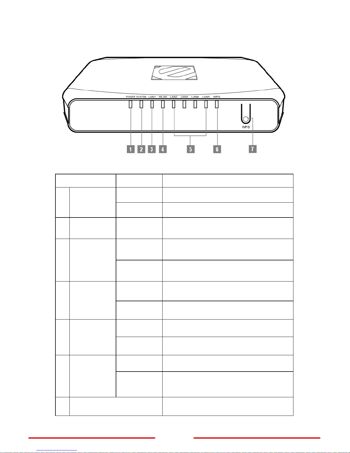
1.3 Front Panel
Note: When the Extender is turned on, the POWER LED lights up and the SYSTEM and WPS
LEDs stay on for 8 seconds to indicate that the system is starting up.
Item Status Description
On
The Extender power is on.
1 POWER LED
Off
The Extender power is off.
2 SYSTEM LED Slow Blinking
The Extender is ready to work.
On
LAN port is successfully connected.
3 LAN LED (1)
Blinking
The Extender is sending or receiving data
over the wired network.
Slow Blinking
Wireless network is ready.
4 WLAN LED
Blinking
The Extender is sending or receiving data
over the wireless network.
On
LAN port is successfully connected.
5
LAN LED
(2/3/4/5)
Blinking
The Extender is sending or receiving data
over the wired network.
Off
The WPS PBC/PIN function is not running.
6 WPS LED
Slow Blinking
The WPS PBC function is enabled. Turns off
after 2 minutes when no connection is
established.
7 WPS Button
Press and hold for 3 seconds to enable the
WPS (Wi-Fi Protected Setup) function.
Page 7
www.encore-usa.com
6
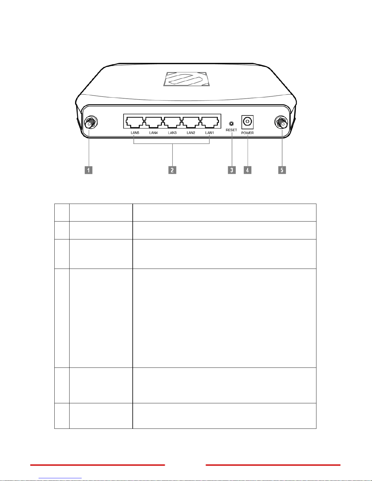
1.4 Back Panel and Connectors
Note: The number of antenna connectors differs per model. The N300 Series has two antenna
connectors (items 1 and 5), while the N150 Series only has one (item 1).
Port / Button Description
1 R-SMA Connector
Attach the external antenna.
2
LAN (1/2/3/4/5)
Ports
Connect wired network and devices, such as a computer,
NAS, IP camera, print server, switch, and access point,
using RJ-45 Ethernet cables.
3 Reset Button
Press and hold the Reset button for 6 seconds to restore the
Extender to its default settings.
Note:
Use a pointed object such as a pen or a paper clip to
press the button.
Using the reset function overrides all user-defined
settings. If you are experiencing problems with the
Extender, perform other troubleshooting methods first
or reset using the web-based configuration utility.
Resetting the Extender should be the last resort.
4 POWER Jack
Connect the supplied power adapter.
Note: Use only the supplied power adapter. Using power
adapters not recommended by the manufacturer may
damage the Ex
tender or the connected devices.
5 R-SMA Connector
Attach the second external antenna.
Note: This port is available only in N300 Series.
Page 8
7
www.encore-usa.com
Chapter 2: Connecting the Extender
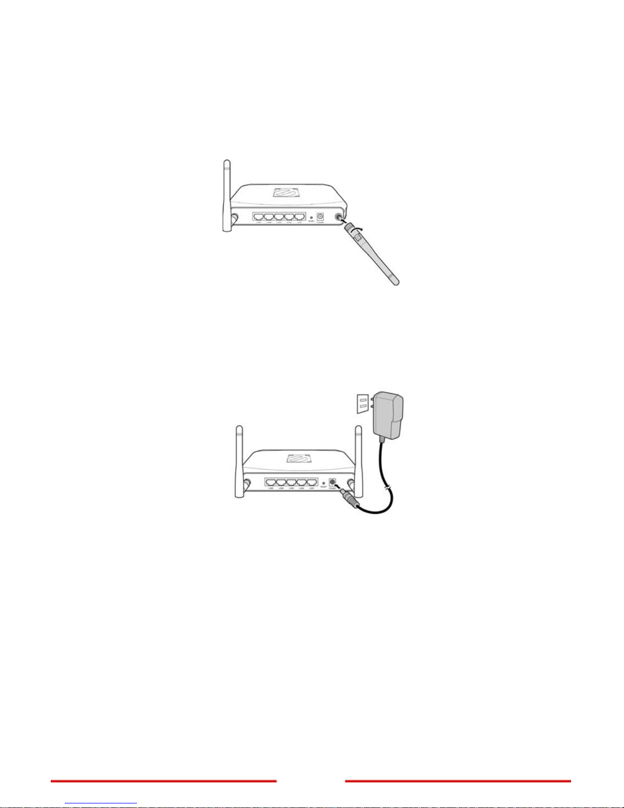
2.1 Setting Up the Extender
1. Attach the antenna(s) to the R-SMA connector(s) at the back of the Extender.
Note: The number of antennas varies depending on model.
2. Position the antenna(s) for proper placement.
3. Connect the power adapter to the power jack of the Extender and then plug the
power adapter to a pow
er outlet.
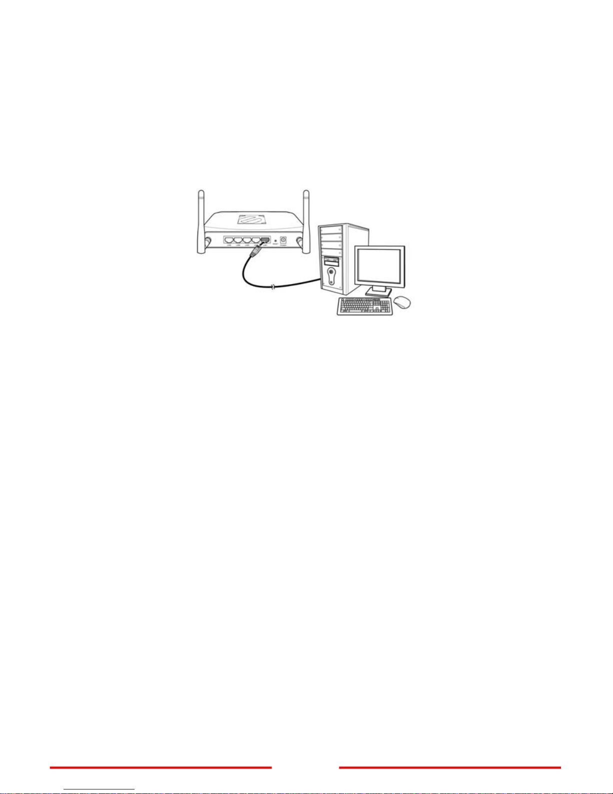
4. Connect a host computer to access the web-based configuration utility.
Note: For initial configuration, it is recommended to connect the host computer to the
LAN port with an Ethernet cable, see Connecting Wired Devices on page 8.
Or
, to connect a
computer wirelessly, search and connect to the Extender
default network:
Network name (SSID): default
Security: disabled
5. After connecting the host computer, configure the computer to be able to
access the web-based configuration utility, see
Accessing the Web-Based
Configuration Utility
on page 13.
Page 9
www.encore-usa.com
8
2.2 Connecting Wired Devices
Use the LAN ports to connect wired devices such as computers, printers, and
Ethernet-enabled game consoles to the Extender.
Connect one end of an Ethernet cable to the LAN port of your device and the other end to
one of the LAN ports of the Extender.
2.3 Checking the Connections
To ensure the Extender and all other connected devices are working properly, check the
LED indicators. For basic connection, the following LED must be lit:
Power LED
System LED (blinking)
LAN L ED (for every device connected via Ethernet)
Page 10

9
www.encore-usa.com
2.4 Identifying the Operation Mode
The Wireless N300 / N150 Extender supports four operation modes. Depending on how
you want to use the Extender, determine the type of mode to use and allocate the
appropriate setup location for the Extender. See Wireless > Basic on p
age 18
to select the
operation mode.
2.4.1 AP Mode
In AP mode, use the Extender as an access point of wireless clients. The Extender has its
own wireless network or network name (SSID) that clients connect to. The Extender
performs tasks that routers do, such as network sharing and broadcasting its SSID.
2.4.2 Repeater Mode
In Repeater mode, the extender works like a bridge between a wireless router and a
wireless client outside the router’s range. The Extender adapts the network name (SSID)
of the wireless router that it is connected to.
Page 11

www.encore-usa.com
10
Note: Data traffic is slower when routed through the Extender compared when directly
connected to the network. It is recommended to use the Extender when a client is in a
“dead spot” where connection to a wireless router is poor or almost impossible.
2.4.3 WDS Mode
In WDS (Wireless Distribution System) mode, the Extender enables interconnection of tw o
or more access points (APs). To use WDS, the access points must support WDS function
and must be configured with the same SSID and WEP key.
2.4.4 AP + WDS Mode
With AP + WDS mode, the Extender acts as the access point to two access points. An
SSID is configured for the Extender. A wireless client connects to the network using the
Extender SSID.
Page 12

11
www.encore-usa.com
Chapter 3: Configuring the Host Computer
Before you begin, the Internet Protocol (TCP/IP) settings of the host computer must be
configured properly to access the Web-based Configuration Utility. Configurations are as
follows:
IP Address : 192.168.10.xxx
(where xxx is a number between 100 ~ 199)
Subnet Mask : 255.255.255.0
3.1 Windows XP
If you are using Windows® XP, follow the instructions below.
1. Click Start > Control Panel > Network Connections.
2. Right-click Local Area Connection (for wired computer) or Wireless Network
Connection (for wireless computer), then click Properties.
3. On the network components list, make sure that Internet Protocol (TCP/IP) is
checked. If not, check it to enable the Properties button.
4. Select Internet Protocol (TCP/IP), and then click Properties.
5. On the General tab, select Use the following IP Address.
6. Enter the IP Address and Subnet Mask of the Extender.
7. Click OK.
3.2 Windows Vista
If you are using Windows® Vista, follow the instructions
below.
1. Click Start > Control Panel > Network and
Internet Connections > Network
Connections.
2. Right-click Local Area Connection (for wired
computer) or Wireless Network Connection
(for wireless computer), then click Properties.
3. On the network components list, make sure that Internet Protocol (TCP/IP) is
checked. If not, check it to enable the Properties button.
Page 13

www.encore-usa.com
12
4. Select Internet Protocol (TCP/IP), and
then click Properties.
5. On the General tab, select Use the
following IP A ddress.
6. Enter the IP Address and Subnet
Mask of the Extender.
7. Click OK.
3.3 Windows 7
If you are using Windows® 7, follow the instructions below.
1. Click Start > Control Panel > Network & Sharing Center.
2. Click Local Area Connection (for wired computer) or Wireless Network
Connection (for wireless computer),
then click Properties.
3. On the network components list, make
sure that Internet Protocol (TCP/IP) is
checked. If not, check it to enable the
Properties button.
4. Select Internet Protocol (TCP/IP), and
then click Properties.
5. On the General tab, select Use the
following IP A ddress.
6. Enter the IP Address and Subnet Mask of the Extender.
7. Click OK.
Page 14

13
www.encore-usa.com
Chapter 4:
Accessing the Web-Based Configuration Utility
Before configuring the Extender, take note of the following default settings.
SSID : default
Channel : 6
Security : Disable
4.1 Login
You need a web browser to access the web-based configuration utility.
1. Open a web browser.
2. Type the following URL on the address bar:
http://192.168.10.1
Sample Screenshot from Internet Explorer
3. The login screen prompts you for a User Name and Password.
Enter the default access information as follows:
User Name : admin
Password : admin
Note: The login screen varies depending on your web browser and the host computer
operating system.
Page 15

www.encore-usa.com
14
4.2 Encore Setup Wizard
Encore Setup Wizard helps you to configure the Extender quickly. Follow the step-by-step
instructions to run the wizard.
1.
To access the Setup Wizard, click Wizard
at the bottom of the menu.
2.
The Setup Wizard overview page is
displayed.
Click Next to continue.
Page 16

15
www.encore-usa.com
3.
On Password and Verify Password, enter
desired password for the Extender
web-based configuration utility.
Click Next to continue.
4.
Leave the LAN IP Address and LAN
Subnet Mask to their default settings.
By default, DHCP Server is “Disabled”. In
most cases, the wired router assigns an IP
address to the Extender when it connects
to the network, so it is recommended to
leave the DHCP Server “Disabled”.
Otherwise, select DHCP Server
“Enabled”, then enter the IP range in
Range Start and Range End.
Click “Next” to continue.
5.
Enter a name for your wireless network on
SSID and select a radio channel in
Channel. These w ill be used by
networking devices to connect to the
Extender.
Click Next to continue.
Page 17

www.encore-usa.com
16
6.
The Setup Wizard is now completed. The
new settings will take effect after the
Extender reboots.
Click Restart to reboot the Extender. If you
do not want to make any changes, click
Exit.
7.
When this window appears, click CLOSE
to close the wizard.
Page 18

17
www.encore-usa.com
Chapter 5: Advanced Configuration
After you log in to the web-based configuration utility, the System > Device Information
screen is displayed.
To access other menu screens, click a menu on the left panel.
After modifying the settings, click the Apply button on the bottom of the screen to save and
apply the configurations.
Page 19

www.encore-usa.com
18
5.1 Wireless
The Wireless menu allows users to set up the wireless network, select the Extender
operation mode, and use Wi-Fi Protected Setup (WPS).
5.1.1 Basic
The Basic screen allows users to select the operation mode, create an SSID, assign the
channel, and set the security settings.
The required parameters on this screen vary depending on the selected operation mode.
Operation Mode — Select an operation mode:
AP (Access Point): The Extender works as an access point for clients in the
wireless network. See
AP Mode on page 19.
Repeater: The Extender repeats the signal from a w ireless ro uter for clients
outside the router range. See
Repeater Mode on page 22.
WDS (Wireless Distribution System): The Extender connects two or more
access points. See
WDS Mode on page 24.
AP + WDS: The Extender acts as the access point to two or more access
points that are connected in a WDS. See
AP + WDS Mode on page 27.
Page 20

19
www.encore-usa.com
5.1.1.1 AP Mode
In AP (Access Point) mode, the Extender acts as an access point with its own SSID and
allows wireless clients to view and connect to the Extender.
SSID — Enter a network name that you want to assign to the Extender. This is the name
that a wireless client searches for to connect to the wireless network via the Extender.
SSID Broadcast — Select Enable to allow wireless clients to view the SSID of the
Extender. Select Disable to hide the SSID.
Channel — Select a transmission channel for wireless communications. The channel of
any wireless client must match the channel selected here to access the network via the
Extender.
Security — When enabled, users are prompted to enter a security key to be allowed
access to the wireless network.
Authentication Type — Select the type of security to use: WEP, WPA, WPA2,
WPA2-Auto.
A. WEP
With WEP (Wired Equivalent Privacy), wireless client s must enter the same key to connect
to the wireless network.
Page 21

www.encore-usa.com
20
Select one of the follow
ing:
Open System: Allows public access to the Extender via wireless connection
but requires users to enter the same WEP key to send and receive data from
the AP.
Share Key: Requires users to enter the same WEP key.
Auto: Select “Auto” if you are unsure which authentication is suitable for your
wireless device.
WEP Key Format — Select a security key format:
HEX: To enter a security key using the characters 0~9, A~F, a~f.
ASCII: To enter a security key in alphanumeric format.
WEP Key Length — Select an encryption length:
64-bit: To enter a 10-character security key.
128-bit: To enter a 26-character security key.
WEP Key — Enter desired security key.
B. WPA / WPA2 / WPA2-Auto with PSK
WPA / WPA2 / WPA2-Auto provides a more secured encryption. If PSK is selected, the
screen below appears:
Encryption Type — Select TKIP, AES, or Auto encryption.
Note: TKIP is available for B or G WLAN band only. The WLAN Band setting is under
Wireless > Advanced menu.
Passphrase and Confirmed Passphrase — Enter a passphrase with at least 8
characters.
Page 22

21
www.encore-usa.com
C. WPA / WPA2 / WPA2-Auto with EAP
Select EAP (Extensible Authentication Protocol) if a Radius server is connected in the
wireless network.
Encryption Type — Select TKIP, AES, or Auto encryption.
Note: TKIP is available for B or G WLAN band only. The WLAN Band setting is under
Wireless > Advanced menu.
Radius Server 1 — Enter the following information:
IP Address: The IP address of the authentication server.
Port: The port number used to connect to the authentication server.
Shared Secret: The secret passphrase to connect to the authentication server.
Page 23

www.encore-usa.com
22
5.1.1.2 Repeater Mode
In Repeater mode, the Extender repeats an access point signal and sends it to wireless
clients outside the access po int range. The Extender uses the SSID of the access point.
1. Click the Search button to search for an access point. A window appears with a
list of available access points.
2. Click Connect of the corresponding access point.
The current access point settings and information are displayed on the screen.
The information varies depending on its settings. Do not change the values of
the following:
SSID
Channel
Security
Page 24

23
www.encore-usa.com
Authentication Type
Encryption Type
PSK / EAP
3. Enter the security key of the selected access point. The screen varies
depending on the access point authentication type.
If the access point security setting is WEP, enter the WEP Key.
If the access point security is WPA / WPA2, enter the passphrase in
Passphrase and Confirmed Passphrase.
4. Click Apply to save and apply the configuration.
Page 25

www.encore-usa.com
24
5.1.1.3 WDS Mode
In WDS (Wireless Distribution System) mode, the Extender connects one or more access
points by their MAC address. When a wireless client belong ing to one access point moves
out of its access point range, the wireless client automatically connects to the other access
point within the WDS. Its wireless network signal continues without interruption.
Channel — Select a transmision channel for wireless communications. The channel of
any wireless client must match the channel selected here to access the network via the
Extender.
WDS Security — Select Enable to prompt users to enter a security key before allowing
access to the wireless network.
WDS Auth T ype — Select the type of security to use: WEP or WPA2.
A. WEP
With WEP (Wired Equivalent Privacy), wireless client s must enter the same key to connect
to the wireless network.
Page 26

25
www.encore-usa.com
WEP Key Format — Select a security key format:
HEX: To enter a security key using the characters 0~9, A~F, a~f.
ASCII: To enter a security key in alphanumeric format.
WEP Key Length — Select an encryption length:
64-bit: To enter a 10-character security key.
128-bit: To enter a 26-character security key.
WEP Key — Enter desired security key.
B. WPA2
WPA2 provides a more secured encryption.
Passphrase and Confirmed Passphrase — Enter a passphrase with at least 8
characters.
To add access points in the WDS, do the following:
1. Click the Search button to search for access points. A window appears with a
list of available access points.
Page 27

www.encore-usa.com
26
2. Cl
ick Connect of the corresponding access point. The MAC address is shown
on MAC.
3. Click the Add button to add the access point to the WDS. The Extender reboots
4. Repeat the above steps to add more access points.
for settings to take effect.
Page 28

27
www.encore-usa.com
5.1.1.4 AP + WDS Mode
In AP + WDS mode, the Extender acts as the access point of the WDS with its own SSID.
Wireless clients can view and connect to the WDS via the Extender.
SSID — Enter a network name that wireless clients can view and connect to.
SSID Broadcast — Select Enable to allow wireless clients to view the SSID of the
Extender. Select Disable to hide the SSID.
Channel — Select a transmission channel for wireless communications.
Page 29

www.encore-usa.com
28
Security — W
hen enabled, users are prompted to enter a security key to be allowed
access to the wireless network.
Authentication Type — Select the type of security to use: WEP, WPA, WPA2,
WPA2-Auto.
A. WEP
With WEP (Wired Equivalent Privacy), wireless client s must enter the same key to connect
to the wireless network.
Select one of the following:
Open System: Allows public access to the Extender via wireless connection
but requires users to enter the same WEP key to send and receive data from
the AP.
Share Key: Requires users to enter the same WEP key.
Auto: Select Auto if you are unsure which authentication is suitable for your
wireless device.
WEP Key Format — Select a security key format:
HEX: To enter a security key using the characters 0~9, A~F, a~f.
ASCII: To enter a security key in alphanumeric format.
WEP Key Length — Select an encryption length:
64-bit: To enter a 10-character security key.
128-bit: To enter a 26-character security key.
WEP Key — Enter desired security key.
B. WPA / WPA2 / WPA2-Auto with PSK
WPA / WPA2 / WPA2-Auto provides a more secured encryption. If PSK is selected, the
screen below appears:
Page 30

29
www.encore-usa.com
Encryption Type — Select TKIP, AES, or Auto encryption.
Note: TKIP is available for B or G WLAN band only. The WLAN Band setting is under
Wireless > Advanced menu.
Passphrase and Confirmed Passphrase — Enter a passphrase with at least 8
characters.
C. WPA / WPA2 / WPA2-Auto with EAP
Select EAP (Extensible Authentication Protocol) if a Radius server is connected in the
wireless network.
Encryption Type — Select TKIP, AES, or Auto encryption.
Note: TKIP is available for B or G WLAN band only. The WLAN Band setting is under
Wireless > Advanced menu.
Radius Server 1 — Enter the following information:
IP Address: The IP address of the authentication server.
Port: The port number used to connect to the authentication server.
Shared Secret: The secret passphrase to connect to the authentication server.
WDS Security — Select Enable to prompt users to enter a security key before allowing
access to the wireless network.
WDS Auth T ype — Select the type of security to use: WEP or WPA2.
Page 31

www.encore-usa.com
30
D. WEP
With WEP (Wired Equivalent Privacy), wireless client s must enter the same key to connect
to the wireless network.
WEP Key Format — Select a security key format:
HEX: To enter a security key using the characters 0~9, A~F, a~f.
ASCII: To enter a security key in alphanumeric format.
WEP Key Length — Select an encryption length:
64-bit: To enter a 10-character security key.
128-bit: To enter a 26-character security key.
WEP Key — Enter desired security key.
E. WPA2
WPA2 provides a more secured encryption.
Passphrase and Confirmed Passphrase — Enter a passphrase with at least 8
characters.
To add access points in the WDS, do the following:
1. Click the Search button to search for access points. A window appears with a
list of available access points.
Page 32

31
www.encore-usa.com
2. Click Connect of the corresponding access point. The MAC address is shown
on MAC.
3. Click the Add button to add the access point to the WDS. The Extender reboots
4. Repeat the above steps to add more access points.
for settings to take effect.
Page 33

www.encore-usa.com
32
5.1.2 Advanced
The Advanced screen allows users to configure advanced wireless functions. This screen
is intended for advanced users. It is recommended to retain the default settings if you are
unsure about them.
Beacon Interval — Enter a beacon interval time between 20 to 1000. The default value is
100. The beacon interval is the frequency interval of sending beacon packets by the
access point to synchronize the wireless network.
RTS Threshold — Enter an RTS (Req uest-To-Send) threshold value. This valu e st abilizes
data flow. If data flow is irregular, only slight modifications should be made.
Fragmentation Threshold — Enter a fragmentation threshold value. If packet transfer
error rates are high, choose values between 1500 and 2346 until packet transfer rates are
minimized.
Note: Setting the fragmentation threshold value too low may diminish system performance.
DTIM Interval — Enter a DTIM (Delivery Traffic Indication Message) interval.
Page 34

33
www.encore-usa.com
The availability of some parameters vary depending on the sele cted WLAN Band.
WLAN Band — Select the type of wireless clients to allow connection with:
B: Allows 802.11b wireless devices only.
G: Allows 802.11g wireless devices only.
B+G: Allows 802.11b and 802.11g wireless devices only.
G+N: Allows 802.11g and 802.11n wireless devices only.
B+G+N: Allows 802.11b, 802.11g, and 802.11n wireless devices.
If the selected WLAN Band is B, G, or B+G, the following parameters are available:
TX Rate — Select the basic transfer rate based on the speed of the Extender .
Preamble Type — Preamble type defines the length of CRC (Cyclic Redundancy Check)
block that detects data transmission errors between the access point and the Extender.
Select Short if the network traffic is high.
WMM — Select Enable to enable the WMM (Wi-Fi Multimedia) feature. This prioritizes
multimedia applications over regular data packets, making multimedia applications run
smoother and with fewer errors.
If the selected WLAN Band is B, G, or B+G, the following parameters are available:
Short GI — Select Enable to reduce the guard interval time and increase data capacity.
Channel Width — Select the channel width:
20MHz: Select if non-802.11n wireless clients are present in the
network.
20/40MHz: Select if 802.11n and non-802.1 1n wireless clients are
present in the network.
Available in WLAN Band:
B, G, or B+G only
Available in WLAN Band:
G+N or B+G+N only
Page 35

www.encore-usa.com
34
20/40MHz Coe
xist — Select Enable to automatically switch between 20MHz and 40MHz
channel width.
Note: This option is only available if Channel Width is 20/40MHz.
STBC — Select Enable to enable the STBC (Space-Time Block Coding) feature. STBC
improves wireless performance by transmitting and receiving multiple copies of data
streams using multiple antennas.
Antenna Transmit Power — Select the antenna transmission power: full, half (-3 dB),
quarter (-6 dB), eighth (-9 dB), or min (minimum).
Click the Apply button on the bottom of the screen to save and apply the settings.
Page 36

35
www.encore-usa.com
5.1.3 Wi-Fi Protec ted Setup
The Wi-Fi Protected Setup screen enables users to configure the Wi-Fi Protected Setup
(WPS) function. WPS allows WPS-enabled clients to join the network even without
knowing the SSID and security key.
WPS — Select Enable to enable the WPS (Wi-Fi Protected Setup) function.
Status — Display the status information of WPS: UnConfigured or Configured.
Self-PIN Number — Display the current PIN number of the Extender.
Client PIN Number — Enter the client PIN number to negotiate with the Extender via
WPS connection. A client can be a network card, IP camera, and etc. Click the Start PIN
button for the Extender to start searching for the client.
Push Button Configuration: The Push Button Configuration (PBC) method allows
WPS-enabled devices to join the network with a push of a button. Click the Start PBC
button and then push the button on the device to establish connection.
Page 37

www.encore-usa.com
36
5.2 LAN
The LAN menu allows users to configure the local area network (LAN) and DHCP
properties.
5.2.1 Basic
The Basic screen contains the local settings of the network. The settings are private and
cannot be seen over the Internet. It is recommended to keep the default values.
Host Name — Enter the host name in the text box. The host name is required by some
ISPs. The default host name is "Encore”.
IP Address — This is the IP address of the Extender. The default IP address is
192.168.10.1.
Subnet Mask — Enter the subnet mask for the Extender. The default subnet mask is
255.255.255.0.
Click the Apply button at the bottom of the screen to save changes.
Page 38

37
www.encore-usa.com
5.2.2 DHCP
The DHCP screen allows users to configure the Extender as the Dynamic Host
Configuration Protocol (DHCP) server. When enabled, the Extender automatically assigns
IP addresses to clients connecting to the network.
A. DHCP
DHCP Server — Select Enable to set the Extender as the DHCP server. Select Disable if
there is already a DHCP server in the network, usually a router.
If DHCP server is enabled, enter the following information.
DHCP Server Start IP — The starting range of IP address that the DHCP
server will use to assign to the clients on t he net work.
DHCP Server End IP — The ending range of IP address that the DHCP
server will use to assign to the clients on t he net work.
Lease Time — Select the lease time from the list. The lease time is the
amount of time a client is allowed to connect to the Extender using its current
dynamic IP address. When the lease time expires, the current IP address is
either renewed or a new one is assigned.
Page 39

www.encore-usa.com
38
All DHCP client computers that
have dynamic IP address are listed in the Dynamic DHCP
List table at the bottom of the screen.
B. Add Static DHCP
The Add Static DHCP feature enables the Extender to always assign the same IP address
(static IP) to a specific client on the network.
Static DHCP — Select Enable to enable this feature.
Name — Enter a name for the client to assign the static IP.
MAC address — Enter the MAC address of the client to which you want to assign the
static IP to.
IP address — Enter the static IP address to assign.
All DHCP clients that are assigned with a static IP are listed in the Static DHCP List table
below.
Click the Apply button at the bottom of the screen to save and apply the configurations.
Page 40

39
www.encore-usa.com
5.3 Access Control
The Acce ss Control menu allows users to define access restrictions of client computers to
access the network.
5.3.1 Filters
The Filters screen allows users to deny or allow a client computer to access the network
based on the MAC address. This screen is divided into two sections: MAC Filter and MA C
Table.
A. MAC Filter
Select an access restriction:
Disabled: Select Disabled to disable the filter.
Only allow computer with MAC address listed below to access the
network: Only the clients listed on the table can access the network.
Only deny computers with MAC address listed below to access the
network: Only the clients listed on the table cannot access the network.
Click the Apply button to saved and apply the access restriction to all n etwork client s listed
on the table at the bottom of the screen.
Page 41

www.encore-usa.com
40
B. MAC Table
Use this section to register network clients. According to the option selected on the MAC
Filter section, the registered clients can be allowed or denied accessing the network. The
registered network clients are listed on the table at the bottom of the screen. (Note: By
clicking on the name of a registered network device on the table, you can update the
device information.)
Name — Enter desired name for the network client to be permitted/denied access.
MAC Address — Enter the MAC address of the network client to be permitted/denied
access.
Add: Click to add the network client to the table.
Update: Click to update a saved network client.
Delete: Click on a network client from the table at the bottom and then click
“Delete” to remove the device.
Clear: Click “Clear” to erase all fields and enter new information.
Page 42

41
www.encore-usa.com
5.4 System
The System menu allows users to change the login password, view the network st atus of
the Extender, view logs and statistics pertaining to connections and p acket transfers, and
update the device firmware.
5.4.1 Password
The Password page allows users to set the administrative and user passwords. These
passwords are used to gain access to the Web-based Configuration Utility.
Administrator — On New Password, type the password the Administrator will use to log
into the system. Retype the same password on Confirm Password.
User — On New Password, type the password the User will use to log into the system.
Retype the same password on Confirm Password.
Click the Apply button at the bottom of the screen to save changes.
Page 43

www.encore-usa.com
42
5.4.2 Device Information
The Device Information screen allows users to view the wireless configurations including
the connected network clients and the LAN stat us of the Extender.
Page 44

43
www.encore-usa.com
5.4.3 Log
The Log screen allows users to view the ongoing activities, events, and statistics of the
Extender. The log displays up to 200 entries. Older entries are overwritten by new entries.
Use the command buttons at the top of the page to manage the Log screen. The command
buttons are as follows:
First Page: Click to view the first page of the log.
Last Page: Click to view the final page of the log.
Previous Page: Click to view the page just before the current page.
Next Page: Click to view the page just after the current page.
Clear Log: Click to delete the contents of the log and begin a new log.
Refresh: Click to refresh the log statistics.
Page 45

www.encore-usa.com
44
5.4.4 Log Setting
The Log Setting screen allows users to configure the SMTP server and send system log
files and alert notifications to the user’s email address. Users can also select the types of
log to include. This screen is divided into two sections: Log Setting and Log Type.
A. Log Setting
Use this section to configure the SMTP server.
SMTP Authentication — Select Enabled if the SMTP server needs authentication. If
enabled, enter the following information:
SMTP Account: Type the SMTP account name.
SMTP Password: T ype the SMTP password.
SMTP Server / IP Address — Type the SMTP server address.
Send From — Type an email address where the log will be sent f r om .
Send to — Type an email address where the log will be sent to. Click the Email Log Now
button to send the current log immediately.
Syslog Server — If you want the Extender to send incoming system log messages, type
Page 46

45
www.encore-usa.com
the IP address of the Syslog server here.
B. Log Type
Use this section to select which items are included in the log. Check the box to include the
following items:
System Activity: Information related to the Extender operation.
Debug Information: Information related to errors and system malfunctions.
Attacks: Information about any malicious activity on the network.
Dropped Packets: Information about packets that have been dropped.
Notice: Important notices by the system administrator.
Click the Apply button at the bottom of the screen to save and apply the settings.
Page 47

www.encore-usa.com
46
5.4.5 Statistic
The Statistic page displays a table that shows the rate of packet transmission via LAN
(wired) and Wireless connections.
Click the Reset button to clear all statistics and to begin logging new statistics again.
Page 48

47
www.encore-usa.com
5.4.6 Restart
In the event the Extender is not performing properly, use the Restart function to reboot the
Extender.
Click the Restart button. A message appears, click the OK button to confirm.
Page 49

www.encore-usa.com
48
5.4.7 Firmware
The Firmware screen allows users to view and update the Extender firmware.
To update the firmware, perform the following steps:
1. On the host computer, download the latest firmware from the Encore web site
(www .encore-usa.com
), and then save the file to the hard disc or to a USB
memory disc.
2. On the Firmware screen, click the Browse button and go to the location of the
saved firmware file.
3. Select the file.
4. Click the Upgrade button to start updating the firmware.
Page 50

49
www.encore-usa.com
5.4.8 Configuration
The Configuration page allows users to save the current setting, load a diff erent setting, or
restore the setting to factory default.
Save Settings — Create a backup file of the current settings.
1. Click the Save button. A message appears.
2. Click Save then browse for the location to save file.
3. Click Save.
Load Settings — Click the Browse button to find the backup settings file. Then, click the
Load button to restore the configuration from the backup file.
Restore Factory Default Settings — Click the Restore button to restore the factory
default settings.
Page 51

www.encore-usa.com
50
5.4.9 UPnP
UPnP (Universal Plug and Play) is a networking architecture that allows automatic
discovery and control of networking equipment, software, and peripherals. This feature is
commonly used for gaming and video streaming.
Select Enable, then click the Apply button to enable this feature.
Page 52

51
www.encore-usa.com
Appendix A. Regulatory Information
A1. Federal Communication Commission Interference Statement
This equipment has been tested and found to comply with the limits for a Class B digital device,
pursuant to Part 15 of the FCC Rules. These limits are designed to provide reasonable
protection against harmful interference in a residential installation. This equipment generates,
uses and can radiate radio frequency energy and, if not installed and used in accordance with
the instructions, may cause harmful interference to radio communications. However, there is
no guarantee that interference will not occur in a particular installation. If this equipment does
cause harmful interference to radio or television reception, which can be determined by turning
the equipment off and on, the user is encouraged to try to correct the interference by one of the
following measures:
- Reorient or relocate the receiving antenna.
- Increase the separation between the equipment and receiver.
- Connect the equipment into an outlet on a circuit different from that to which the receiver
is connected.
- Consult the dealer or an experienced radio/TV technician for help.
FCC Caution: Any changes or modifications not expressly approved by the party responsible for
compliance could void the user's authority to operate this equipment.
This device complies with Part 15 of the FCC Rules. Operation is subject to the following two
conditions: (1) This device may not cause harmful interference, and (2) this device must accept
any interference received, including interference that may cause undesired operation.
IMPORTANT NOTE:
FCC Radiation Exposure Statement:
This equipment complies with FCC radiation exposure limits set forth for an uncontrolled
environment. This equipment should be installed and operated with minimum distance 20cm
between the radiator & your body.
This transmitter must not be co-located or operating in conjunction with any other antenna or
transmitter.
The availability of some specific channels and/or operational frequency bands are country
dependent and are firmware programmed at the factory to match the intended destination. The
firmware setting is not accessible by the end user.
Page 53

www.encore-usa.com
52
A2. Europe – EU Declaration of Conformity
This device complies with the essential requirements of the R&TTE Directive 1999/5/EC. The
following test methods have been applied in order to prove presumption of conformity with the
essential requirements of the R&TTE Directive 1999/5/EC:
EN 60 950-1: 2001 +A11: 2004
Safety of Information Technology Equipment
EN 50385: 2002
Product standard to demonstrate the compliance of radio base stations and fixed terminal
stations for wireless telecommunication systems with the basic restrictions or the reference
levels related to human exposure to radio frequency electromagnetic fields (110MHz - 40 GHz) General public
EN 300 328 V1.7.1 (2006-10)
Electromagnetic compatibility and Radio spectrum Matters (ERM); Wideband transmission
systems; Data transmission equipment operating in the 2,4 GHz ISM band and using wide band
modulation techniques; Harmonized EN covering essential requirements under article 3.2 of the
R&TTE Directive
EN 301 489-1 V1.6.1 (2005-09)
Electromagnetic compatibility and Radio Spectrum Matters (ERM); ElectroMagnetic
Compatibility (EMC) standard for radio equipment and services; Part 1: Common technical
requirements
EN 301 489-17 V1.2.1 (2002-08)
Electromagnetic compatibility and Radio spectrum Matters (ERM); ElectroMagnetic
Compatibility (EMC) standard for radio equipment and services; Part 17: Specific conditions for
2,4 GHz wideband transmission systems and 5 GHz high performance RLAN equipment
This device is a 2.4 GHz wideband transmission system (transceiver), intended for use in all EU
member states and EFTA countries, except in France and Italy where restrictive use applies.
In Italy the end-user should apply for a license at the national spectrum authorities in order to
obtain authorization to use the device for setting up outdoor radio links and/or for supplying
public access to telecommunications and/or network services.
This device may not be used for setting up outdoor radio links in France and in some areas the
RF output power may be limited to 10 mW EIRP in the frequency range of 2454 – 2483.5 MHz.
For detailed information the end-user should contact the national spectrum authority in France.
0560
Page 54

53
www.encore-usa.com
Česky [Czech]
Encore Electronics Inc. tímto prohlašuje, že tento ENXWI-1AN4x / ENXWI-2AN4x je ve
shodě se základními požadav ky a dalšími přís lušný mi ust an ovení mi sm ěrnice 199 9/5/ES.
Dansk [Danish]
Undertegnede Encore Electronics Inc erklærer herved, at følgende udstyr ENXWI-1AN4x
/ ENXWI-2AN4x overholder de væsentlige krav og øvrige relevante krav i direktiv
1999/5/EF.
Deutsch [German]
Hiermit erklärt Encore Electronics Inc, dass sich das Gerät ENXWI-1AN4x /
ENXWI-2AN4x in Übereinstimmung mit den grundlegenden Anforderungen und den
übrigen einschlägigen Bestimmungen der Richtlinie 1999/5/EG befindet.
Eesti [Estonian]
Käesolevaga kinnitab Encore Electronics Inc seadme EN XWI-1AN4x / ENXWI-2AN4x
vastavust direktiivi 1999/5/EÜ põhinõuetele ja nimetatud direktiivist tulenevatele teistele
asjakohastele sätetele.
English
Hereby, Encore Electronics Inc, declares that this ENXWI-1AN4x / ENXWI-2AN4x is in
compliance with the essential requirements and other relevant provisions of Directive
1999/5/EC.
Español [Spanish]
Por medio de la presente Encore Electronics Inc declara que el ENXWI-1AN4x /
ENXWI-2AN4x cumple con los requisitos esenciales y cualesquiera otras disposiciones
aplicables o exigibles de la Directiva 1999/5/CE.
Ελληνική [Greek]
ΜΕ ΤΗΝ ΠΑΡΟΥΣΑ Encore Electronics Inc ΔΗΛΩΝΕΙ ΟΤΙ ENXWI-1AN4x /
ENXWI-2AN4x ΣΥΜΜΟΡΦΩΝΕΤΑΙ ΠΡΟΣ ΤΙΣ ΟΥΣΙΩΔΕΙΣ ΑΠΑΙΤΗΣΕΙΣ ΚΑΙ ΤΙΣ
ΛΟΙΠΕΣ ΣΧΕΤΙΚΕΣ ΔΙΑΤΑΞΕΙΣ ΤΗΣ ΟΔΗΓΙΑΣ 1999/5/ΕΚ.
Français [French]
Par la présente Encore Electronics Inc déclare que l'appareil ENXWI-1AN4x /
ENXWI-2AN4x est conforme aux exigences essentielles et aux autres dispositions
pertinentes de la directive 1999/5/CE.
Italiano [Italian]
Con la presente Encore Electronics Inc dichiara che questo ENXWI-1AN4x /
ENXWI-2AN4x è conforme ai requisiti essenziali ed alle altre disposizioni pertinenti
stabilite dalla direttiva 1999/5/CE.
Latviski [Latvian]
Ar šo Encore Electronics Inc deklarē, ka ENXWI-1AN4x / ENXWI-2AN4x atbilst
Direktīvas 1999/5/EK būtiskajām prasībām un citiem ar to saistītajiem noteikumiem.
Lietuvių [Lithuanian]
Šiuo Encore Electronics Inc deklaruoja, kad šis ENXWI-1AN4x / ENXWI-2AN4x atitinka
esminius reikalavimus ir kitas 1999/5/EB Direktyvos nuostatas.
Nederlands [Dutch]
Hierbij verklaart Encore Electronics Inc dat het toestel ENXWI-1AN4x / ENXWI-2AN4x in
overeenstemming is met de essentiële eisen en de andere relevante bepalingen van
richtlijn 1999/5/EG.
Malti [Maltese]
Hawnhekk, Encore Electronics Inc, jiddikjara li dan ENXWI-1AN4x / ENXWI-2AN4x
jikkonforma mal-ħtiġijiet essenzjali u ma provvedimenti oħrajn relevanti li hemm
fid-Dirrettiva 1999/5/EC.
Magyar [Hungarian]
Alulírott, Encore Electronics Inc nyilatkozom, hogy a ENXWI-1AN4x / ENXWI-2AN4x
megfelel a vonatkozó alapvetõ követelményeknek és az 1999/5/EC irányelv egyéb
elõírásainak.
Polski [Polish]
Niniejszym Encore Electronics Inc oświadcza, że ENXWI-1AN4x / ENXWI-2AN4x jest
zgodny z zasadniczymi wymogami oraz pozostałymi stosownymi postanowieniami
Dyrektywy 1999/5/EC.
Português [Portuguese]
Encore Electronics Inc declara que este ENXWI-1AN4x / ENXWI-2AN4x está conforme
com os requisitos essenciais e outras disposições da Directiva 1999/5/CE.
Slovensko [Slovenian]
Encore Electronics Inc izjavlja, da je ta ENXWI-1AN4x / ENXWI-2AN4x v skladu z
bistvenimi zahtevami in ostalimi relevantnimi določili direktive 1999/5/ES.
Slovensky [Slovak]
Encore Electronics Inc týmto vyhlasuje, že ENXWI-1AN4x / ENXWI-2AN4x spĺňa
základné požiadavky a všetky príslušné ustanovenia Smernice 1999/5/ES.
Suomi [Finnish]
Encore Electronics Inc vakuuttaa täten että ENXWI-1AN4x / ENXWI-2AN4x tyyppinen
laite on direktiivin 1999/5/EY oleellisten vaatimusten ja sitä koskevien direktiivin muiden
ehtojen mukainen.
Svenska [Swedish]
Härmed intygar Encore Electronics Inc att denna ENXWI-1AN4x / ENXWI-2AN4x står I
överensstämmelse med de väsentliga egenskapskrav och övriga relevanta
bestämmelser som framgår av direktiv 1999/5/EG.
Page 55

www.encore-usa.com
54
Appendix B. Software End User License Agreement
PLEASE READ THE FOLLOWING TERMS ("Agreement") CAREFULLY. USE OF THE
SOFTWARE (defined below) PROVIDED BY ENCORE ELECTRONICS, INC. IS PERMITTED
ONL Y UNDER AND IN ACCORDANCE WITH THIS AGREEMENT. IF YOU DO NOT AGREE
TO BE BOUND BY THIS AGREEMENT, PLEASE DO NOT USE THIS SOFTWARE.
1. Grant of License. This Agreement permits you to use one copy of the Software or the
Software included in this package or device on any single computer ("Software"). For each
software licensee, the program can be "in use" on only one computer or hardware device at any
given time. The Software is "in use" when it is either downloaded, copied, loaded into RAM or
installed into the hard disk or other permanent memory of a computer or other hardware device.
2. License Restrictions. YOU MAY NOT RENT, LEASE, SUBLICENSE, SELL, ASSIGN,
LOAN OR OTHERWISE TRANSFER THE SOFTWARE OR ANY OF YOUR RIGHTS AND
OBLIGATIONS UNDER THIS AGREEMENT. You may not modify, translate, reverse assemble,
decompile, disassemble or otherwise attempt (i) to defeat, avoid, bypass, remove, deactivate or
otherwise circumvent any software protection mechanisms in the Software, including without
limitation any such mechanism used to restrict or control the functionality of the Software, or (ii)
to derive the source code or the underlying ideas, algorithms, structure or organization from the
Software (except to the extent that such activities may not be prohibited under applicable law).
However, you may transfer all your right to use the Software to another person or organization,
provided that (a) the followings are also transferred with the Software, (i) this Agreement; (ii)
other software if contained in the original package, and/or hardware that the Software is bundled;
(iii) any original or updated version of the Software; (b) no copies including back-up and installed
in your computer or other device are at your possession after the transfer, and (c) the recipient
accepts all the terms of this Agreement. In no event shall you transfer the Software obtained as
a trial, test version, or otherwise specified as not for resale. A special license permit from
Encore Electronics, Inc. is required if the program is going to be installed on a network server for
the sole purpose of distribution to other computers.
3. Copyright. The Software or the Software contained in this package or device is protected
by United States copyright laws, international treaty provisions, and all other applicable national
laws. The Software must be treated like all other copyrighted materials (e.g. books and
musical recordings). This license does not allow the Software to be rented or leased, and the
written materials accompanying the Software (if any) may not be copied.
4. Ownership. Title, ownership rights, and all intellectual property rights in and to the Software
and any accompanying documentation, and any copy of the foregoing, and any sample contents
shall remain the sole and exclusive property of Encore Electronics, Inc. and/or its third party
licensors. You agree to abide by the copyright law and all other applicable laws. You
acknowledge that the Software contains valuable confidential information and trade secrets of
Encore Electronics, Inc. and/or its third party licensors.
5. Warranty Disclaimer . THE SOFTWARE IS MADE AVAILABLE TO YOU ON "AS IS" BASIS.
NO WARRANTIES, EITHER EXPRESS OR IMPLIED, ARE MADE WITH RESPECT TO THIS
SOFTWARE, INCLUDING BUT NOT LIMITED TO THE IMPLIED WARRANTIES OF
Page 56

55
www.encore-usa.com
MERCHANTABILITY AND FITNESS FOR A PARTICULAR PURPOSE AND WARRANTIES
FOR NON-INFRINGEMENT OF INTELLECTUAL PROPERTY, AND ENCORE ELECTR ONICS,
INC. EXPRESSLY DISCLAIMS ALL WARRANTIES NOT STATED HEREIN. YOU ASSUME
THE ENTIRE RISK AS TO THE QUALITY AND PERFORMANCE OF THE SOFTWARE.
SHOULD THE SOFTWARE PROVE DEFECTIVE, YOU, AND NOT ENCORE ELECTRONICS,
INC. OR AN AUTHORIZED RESELLER, ASSUME THE ENTIRE COST OF NECESSARY
SERVICING, REPAIR, OR CORRECTION. SOME STATES DO NOT ALLOW THE
EXCLUSION OF IMPLIED WARRANTIES, SO THE ABOVE EXCLUSION MAY NOT APPLY TO
YOU. THIS WARRANTY GIVES YOU SPECIFIC LEGAL RIGHTS, AND YOU MAY ALSO
HAVE OTHER RIGHTS THAT VARY FROM STATE TO STATE. YOUR SOLE REMEDY AND
THE ENTIRE LIABILITY OF ENCORE ELECTRONICS, INC. ARE SET FORTH ABOVE.
6. No Liability for Consequential Damages. YOU AGREE THAT IN NO EVENT SHALL
ENCORE ELECTRONICS, INC. OR ITS AGENTS BE LIABLE FOR ANY LOSS OF
ANTICIPATED PROFITS, LOSS OF DATA, LOSS OF USE, BUSINESS INTERRUPTION,
COST OF COVER OR ANY OTHER INDIRECT, INCIDENTAL, SPECIAL, PUNITIVE OR
CONSEQUENTIAL DAMAGES WHATSOEVER ARISING OUT OF THE USE OF OR INABILITY
TO USE THE SOFTWARE, HOWEVER CAUSED AND ON ANY THEORY OF LIABILITY
(WHETHER FOR BREACH OF CONTRACT, TORT (INCLUDING NEGLIGENCE) OR
OTHERWISE), EVEN IF ENCORE ELECTRONICS, INC. HAS BEEN ADVISED OF THE
POSSIBILITY OF SUCH DAMAGES. IN NO EVENT WILL ENCORE ELECTRONICS, INC. BE
LIABLE TO YOU FOR DAMAGES IN AN AMOUNT GREATER THAN THE FEES PAID FOR
THE USE THE FOREGOING LIMITATIONS APPLY TO THE EXTENT PERMITTED BY
APPLICABLE LAWS IN YOUR JURISDICTION.
7. Export. You will not export or re-export the product incorporating the Software without the
appropriate United States or foreign government licenses.
8. U.S. Government Restricted Rights. If you are a unit or agency of the United States
government, the Software and related documentation are deemed to be "commercial computer
software" and "commercial computer software documentation," respectively, pursuant to DFAR
Section 227.7202 and FAR Section 12.212(b), as applicable. Any use, modification,
reproduction, release, performing, displaying or disclosing of the Software and/or the related
documentation by the United States government shall be governed solely by the terms of this
Agreement and shall be prohibited except to the extent expressly permitted by the terms of this
Agreement. Any technical data provided that is not covered by the above provisions is deemed
to be "technical data commercial items" pursuant to DFAR Section 227.7015(a). Any use,
modification, reproduction, release, performing, displaying or disclosing of such technical data
shall be governed by the terms of DFAR Section 227.7015(b).
9. Termination. THIS AGREEMENT SHALL BE EFFECTIVE UPON INSTALLATION OF THE
SOFTWARE AND SHALL TERMINATE UPON THE EARLIER OF: (i) YOUR FAILURE TO
COMPL Y WITH ANY TERM OF THIS AGREEMENT; OR (ii) RETURN, DESTRUCTION OR
DELETION OF ALL COPIES OF THE SOFTWARE IN YOUR POSSESSION. Encore
Electronics, Inc.'s rights and your obligations shall survive the termination of this Agreement.
10. High Risk Activities. The Software is not fault-tolerant and is not designed or intended for
use in hazardous environments requiring fail-safe performance, or any other application in which
the failure of the Software could lead directly to death, personal injury, or severe physical or
Page 57

56
www.encore-usa.com
property damage (collectively, "High Risk Activities"). Encore Electronics, Inc. EXPRESSLY
DISCLAIMS ANY EXPRESS OR IMPLIED WARRANTY OF FITNESS FOR HIGH RISK
ACTIVITIES.
11. Governing Law and Jurisdiction. This Agreement will be governed by and construed
under the laws of the State of California. and the United States as applied to agreements entered
into and to be performed entirely within California., without regard to conflicts of laws provisions
thereof and the parties expressly exclude the application of the United Nations Convention on
Contracts for the International Sales of Goods. Suits or enforcement actions must be brought
within, and each party irrevocably commits to the exclusive jurisdiction of the state and federal
courts located in Santa Clara County.
Appendix C. User’s Notice
No part of this manual, including the products and software described in it, may be
reproduced, transmitted, transcribed, stored in a retrieval system, or translated into any
language in any form or by any means, except documentation kept by the purchaser for backup
purposes, without the express written permission of us.
WE PROVIDES THIS MANUAL “AS IS” WITHOUT WARRANTY OF ANY KIND, EITHER
EXPRESS OR IMPLIED, INCLUDING BUT NOT LIMITED TO THE IMPLIED W ARRANTIES OR
CONDITIONS OF MERCHANTABILITY OR FITNESS FOR A PARTICULAR PURPOSE. IN NO
EVENT SHALL US, ITS DIRECTORS, OFFICERS, EMPLOYEES OR AGENTS BE LIABLE
FOR ANY INDIRECT, SPECIAL, INCIDENTAL, OR CONSEQUENTIAL DAMAGES
(INCLUDING DAMAGES FOR LOSS OF PROFITS, LOSS OF BUSINESS, LOSS OF USE OR
DATA, INTERRUPTION OF BUSINESS), EVEN IF WE HAS BEEN ADVISED OF THE
POSSIBILITY OF SUCH DAMAGES ARISING FROM ANY DEFECT OR ERROR IN THIS
MANUAL OR PRODUCT.
Product warranty or service will not be extended if: (1) the product is repaired, modified or
altered, unless such repair, modification of alteration is authorized in writing by us; or (2) the
serial number of the product is defaced or missing.
Products and corporate names appearing in this manual may or may not be registered
trademarks or copyrights of their respective companies, and are used only for identification or
explanation and to the owners’ benefit, without intent infringe.
Windows
®
7, Windows Vista® and Windows® XP are registered trademarks of Microsoft®
Corporation.
Adobe
®
and Acrobat® are registered trademarks of Adobe Systems Incorporated.
SPECIFICATIONS AND INFORMATION CONTAINED IN THIS MANUAL ARE
FURNISHED FOR INFORMATION USE ONLY, AND ARE SUBJECT TO CHANGE AT ANY
TIME WITHOUT NOTICE, AND SHOULD NOT BE CONSTRUED AS A COMMITMENT BY US.
WE ASSUME NO RESPONSIBILITY OR LIABILITY FOR ANY ERRORS OR INACCURACIES
THAT MAY APPEAR IN THIS MANUAL, INCLUDING THE PRODUCTS AND SOFTWARE
DESCRIBED IN IT.
 Loading...