

Page 1
© 2010 Encore Electronics, Inc. All rights reserved.COVER
© 2010 Encore Electronics, Inc.
Product specifications, size, and shape are subj ect to change w ithout not ice , an d act ual product appearance m ay dif fe r f rom that depicted herein.
All trademarks and brand names are the properties of their respective holders.
Page 2

www.encore-usa.com
TABLE OF CONTENTS
REVISION HISTORY .............................................................................................. 4
INTRODUCTION ................................................................................................... 5
FEATURES .............................................................................................................. 5
SPECIFICATIONS ..................................................................................................... 6
PACKAGE CONTENTS ............................................................................................. 7
SYSTEM REQUIREMENTS........................................................................................ 7
LEDS INDICATION & CONNECTORS OF WIRELESS ROUTER ................................... 7
INSTALLATION INSTRUCTION ................................................................................. 8
PC NETWORK TCP/IP SETTING ....................................................................... 9
WINDOWS 95/98/ME ............................................................................................. 9
WINDOWS 2000 ..................................................................................................... 9
WINDOWS XP / VISTA / 7 ..................................................................................... 10
CONFIGURATION ............................................................................................... 11
LOGIN TO THE WLAN ROUTER THROUGH WIRELESS LAN ................................. 12
LOGIN TO THE WLAN ROUTER............................................................................ 12
USING THE WEB BROWSER .................................................................................. 12
SETUP WIZARD .................................................................................................... 12
ADVANCED CONFIGURATION ................................................................................ 22
WAN ................................................................................................................... 22
Connection Type ............................................................................................. 22
Dynamic DNS ................................................................................................. 28
WIRELESS ............................................................................................................ 29
Basic ............................................................................................................... 29
Security ........................................................................................................... 30
Advanced ........................................................................................................ 33
Wi-F i Protected Setup .................................................................................... 34
LAN .................................................................................................................... 35
1
Page 3

www.encore-usa.com
Basic ............................................................................................................... 35
DHCP ............................................................................................................. 35
ROUTING.............................................................................................................. 36
Static ............................................................................................................... 36
Dynamic ......................................................................................................... 37
Routing Table ................................................................................................. 37
ACCESS CONTROL ............................................................................................... 38
Filters ............................................................................................................. 38
Virtual Server ................................................................................................. 44
Special AP ...................................................................................................... 45
DMZ ............................................................................................................... 46
Firewall Rule .................................................................................................. 47
SYSTEM ............................................................................................................... 49
Password ........................................................................................................ 49
Time ................................................................................................................ 50
Device Information ......................................................................................... 51
Log ................................................................................................................. 52
Log Setting ..................................................................................................... 53
Statistic ........................................................................................................... 54
Restart ............................................................................................................ 55
Firmware ........................................................................................................ 56
Configuration ................................................................................................. 57
UPnP .............................................................................................................. 58
Ping Test ......................................................................................................... 59
Remote Management ...................................................................................... 60
SETTING THE ENHWI-1AN4 AS AN ACCESS POINT. ............................................ 61
Product specifications, size, and shape are subject t o change without notice, and actual
product appearance may differ from that depicted herein.
All trademarks and brand names are the properties of their respective holders.
© 2010 Encore Elect ronics, Inc. All rights reserved.
2
Page 4

www.encore-usa.com
FCC Warning
This equipment has been tested and found to c omply with the li mits for a Class C digital
device, pursuant to part 15 of the FCC Rules. These limits are designed to provide
reasonable protection against harmful interference in a residential installation. This
equipment generates , uses, and can radiat e radio frequency ener gy and, if not install ed
and used in accordance with the instructions, may cause harmful interference to radio
communication. However, there is no guarantee that interference will not occur in a
particular installation. If this equipment does cause harmful interference to radio or
television rec eption, which can be determined by turni ng the equipment off and on, the
user is encouraged to try to correct the interference by one or more of the following
measures:
- Reorient or rel ocate the receiving antenna.
- Increase the separat ion between the equipment and receiver.
- Connect the equipme nt int o an out let on a c irc uit di fferent fr om that to whi c h the r ecei ver
is connected.
- Consult the dealer or an experienced radio/TV technician f or help.
FCC Caution: Any changes or modifications not expressly approved by the party
responsible for compliance could void the user’s authority to operate t his equipment.
This device compl ies wit h Part 15 of t he FCC Rules . Operati on is subject to the f ollowing
two conditions: (1) This device may not cause harm ful interference, and (2) this device
must accept any inter ference received, incl uding interference that may c ause undesired
operation.
IMPORTANT NOTE:
FCC Radiation Exposure Statement:
This equipment c omplies with FCC r adiation exposur e limits set fort h for an uncontrol led
environment. This equipment should be installed and operated with a minimum distance of
about eight inches (20cm) between the radiator and your body.
This transmitt er must not be co-locat ed or oper ated in c onjunct ion w ith any ot her ante nna
or transmitter. IEEE802.11b or 802.11g operation of this product in the USA is
firmware-limited to channels 1 through 11.
3
Page 5

www.encore-usa.com
Notice:
Changes or modifi cations to the equipment, which are not appr oved by the party
responsible for compliance, could aff ect the user's author ity to operate the equi pment.
Company has an on-going policy of upgrading its products and it may be poss ible that
information in t his document is not up-to-dat e. Please check with your local distribut ors
for the latest information.
Revision History
Revision History
V1.0 1st release
4
Page 6
www.encore-usa.com
Introduction
The ENHWI-1AN4 Wireless N150 Router complies with IEEE 802.11n, and provides faster
and farther range than 802.11g while being backward compatible with 802.11g and
802.11b mode. This router uses advanc ed broadband router chipset and wirel ess LAN
chipset solution to let you enjoy high-speed Wired and Wireless connection. Simply
connect this devi ce to a Cable or DSL modem and th en you can share y our high-speed
Internet acces s with multi ple PCs at your home with or wi thout wir es. It creat es a secure
Wired and Wireless network for you to share photos, files, video, music, printer and
network storage. ENHWI-1AN4 provides maximum transfer rate up to 150Mbps and
supports WEP, WPA, WPA2, 802.1x high-level WLAN security featur es that gu arant ee t he
best security for users.
Features
Up to 150 Mbps data transfer rates
Backward compatibl e w ith IEEE 802.11b/g
Built-in 4 port 10/100 Ethernet switch with auto speed sensing
Supports Access Point
Supports NAT, DHC P Ser ver/Client
Supports VPN pass through - IPSec, PPTP, L2TP
Supports Virtual Server / Port Trigger
Supports Virtual DMZ Host, DDNS, UPnP
Supports 64/128-bit WEP, WPA, WPA2, 802.1x Authentication Encryption
Supports WPS software PBC/PIN
Supports MAC Filt er, IP Filter, URL/Domain Blocking, P rotocol Filter
Supports Auto-crossover (MDI/MDI-X) function
Supports software upgrade through Web
Friendly web-based GU I Configuration and Management
5
Page 7

www.encore-usa.com
150Mbps (802.11n mode)
11Mbps ( 802.11b mode)
IEEE 802.11b / 802.11g / 802.11n (Wireless)
IEEE 802.3x Full Duplex Flow Control (Wired)
Support UPnP (Internet Gateway Device)
Support 64/128-bit WEP Data Encryption
Support MAC filter
Web-based GUI Configuration / Management
Support Configuration setting Backup/Restore/Reset to Default
Interface
LAN x 4, WAN x 1
LED Indicators
POWER, STATUS, LAN x 4, WAN x 1, WLAN x 1
Antenna
One 2dBi Dipole Antenna
Wireless Frequenc y
2.4000~2.4835GHz
Output Power
15 dBm
IEEE 802.11b : -88 dBm (T ypical),
IEEE 802.11n: 20Mhz -68dBm ; 40Mhz -65dBm (Typical)
Transmit Output Pow er
11b : 18±1 dBm, 11g : 15±1 d Bm , 11n : 15±1 dBm
Power
DC 9V 0.5A
Dimensions (approx.)
14.5 x 9.6 x 2.6 cm (W x L x H)
Net Weight (approx.)
152.1 g
Specifications
Data Transfer Rat es
Standard
Operating Radius 100m Indoor, 300m Outdoor
Internet Access
WAN Connection Dynamic IP, Static IP, PPPoE, PPTP, L2TP
IP Management
Security
Firewall
54Mbps ( 802.11g mode)
IEEE 802.3,
IEEE 802.3u,
Connect to Broadba nd (Cable or xDSL) modem or
Ethernet backbone for Internet Surfing
NAT (Network Address Translation)
DHCP (Dynamic Host Configuration Protoc ol) Server/Client
Support VPN pass through – IPSec, PPTP, L2TP
Support Virtual ser ver / Port Trigger
Support Virtual DMZ host
Support Dynamic DNS
Support WPA, WPA2 (802.11i) security
Support WPS software PBC/PIN
Support MAC ACL (MAC Access Control List)
Support PAP / CHAP / M S-CHAP / MS-CHAPv2 authentication
Support 802.1x RADIUS Server
Support IP filter
Support URL/Domain Blocking
Support Protocol Filter
Web Remote Login from WAN
Management
Receiver Sensitivity
Software Upgrade through Web
Support NTP update
Support System Log
IEEE 802.11g : -70dBm (T ypical)
6
Page 8
www.encore-usa.com
Operating Temperat ure
0°C ~ 40°C
Humidity
5 % ~ 95 % (non-condensing)
Storage Temperatur e
0°C ~ 70°C
Supported OS
Windows 98SE, ME, 2000, XP, Vista, Win7, Mac and Linu x
Regulations
FCC, CE
Package Contents
One ENHWI-1AN4 Wireless N150 Router
One 2dBi Dipole Antenna
One External Power Adapter
One CD-ROM with User’s Manual
One RJ-45 Ethernet Ca ble
One type-A to type-C plug converter
System Requirements
Computers with an i nstalled Ethernet adapter.
Valid Internet Access account and Ethernet based DSL or Cable modem.
10/100Base-T Ethernet cable with RJ-45 connector.
TCP/IP protocol must be installed on all PCs.
System with Windows Internet Explorer 7 or later,
or Mozilla Firefox 3 or later.
LEDs Indication & Connectors of Wireless Router
Front Panel LEDs I ndication
LED Light Status Description
PWR
WLAN Slow Blinking WLAN is successfully connected.
On Wireless Router is powered on.
Off Wireless Router is powered off.
7
Page 9
www.encore-usa.com
en
e, such as the
9V) packaged with
Blinking Data is being sent or received.
WAN On WAN port is successfully connected
Blinking Data is being sent or received.
LAN
(1, 2, 3, 4)
Back Panel Connectors
Button/Port Description
Reset Reset configurations to default. You would use the reset button only wh
LAN
(1x, 2x, 3x, 4x)
WAN Ethernet RJ-45 connec tor, connect to WAN access devic
DC-9V Power connector, connect to the power adapt er (DC-
Installation Instruction
1) Power off the DSL or Cable modem.
2) Connect computer to the LAN port on the ENHWI-1AN4 Router w ith Ethernet
cable.
3) Connect the DSL or Cable modem to the WAN port on the ENHWI-1AN4 Router
with Ethernet cable.
4) Power on the DSL or Cable modem first, and then connect power adapter to the
power jack on the rear panel of ENHWI-1AN4 Router and pl ug the pow er cable
into an outlet.
5) Check LEDs.
On LAN port is successfully connected.
Blinking Data is being sent or received.
a program error has caused your W ireless AP rout er to hang. Pres s the
button and hold after 6 seconds.
Ethernet RJ-45 connector, connect to PC with a RJ-45 Ethernet cable.
Cable modem or ADSL modem.
the AP router.
8
Page 10
www.encore-usa.com
a) Once power on the ENHWI-1AN4 Router, Power LED should be on.
b) LAN LED should be on for each active LAN connection.
c) The WAN LED should be on when the DSL or Cable modem is
connected.
PC Network TCP/IP Setting
The network TCP/IP sett ings differ based on the comp uter’s operating system
(Win95/98/ME/NT/2000/XP/Vista) and are as follows.
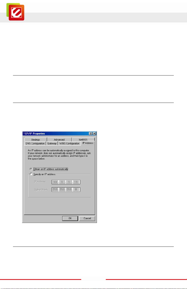
Windows 95/98/ME
1. Cli ck on the “Network neighbor hood” icon found on the des ktop.
2. Cli ck the right mouse but ton and a context menu wil l be show.
3. Selec t “Properties” to enter the TCP/IP setting screen.
4. Selec t “Obtain an IP address automatically” on the “I P addr ess” field.
Windows 2000
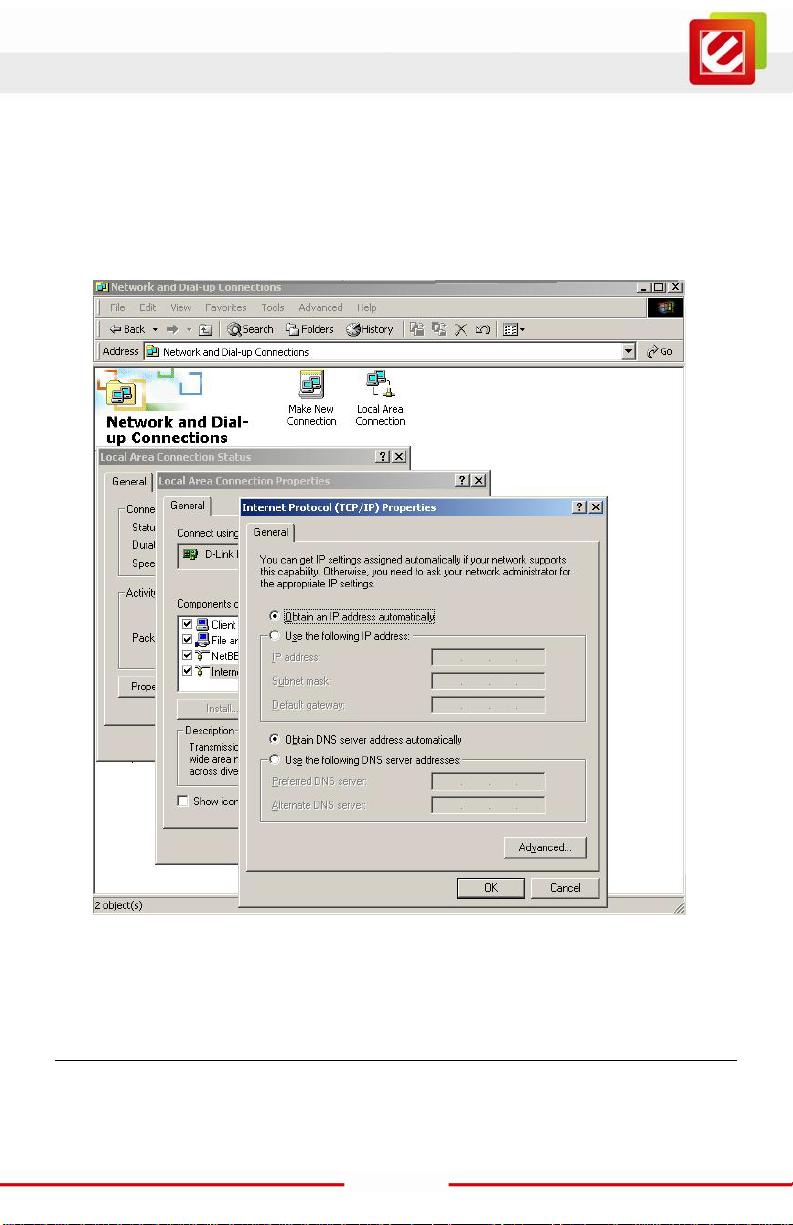
Double click on the “My Computer” icon on the desktop. When “My Computer” window
opens, selects “Control Panel” and then opens the “Network dialup connection” appl et.
9
Page 11
www.encore-usa.com
Double click on the “Local area network connection” ic on. Select “Properties” to enter the
TCP/IP setting window.
1. In the “Local area network status” window, click on “Properties.”
2. In the “ Local area net wor k connecti on” window, first s elect TCP/ I P setti ng and then
select “Properties.”
3. Set bot h “IP address” and “DNS” t o Automatic configuration.
Windows XP / Vista / 7
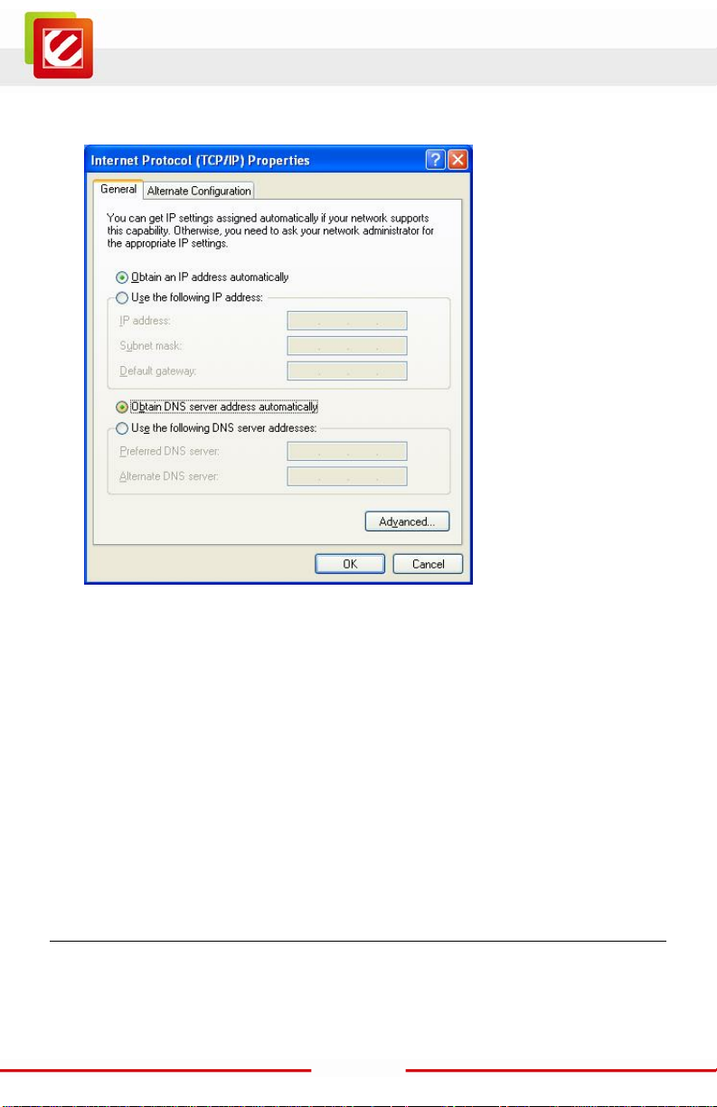
Point the cursor and click the right button on the “My Network Place” icon.
Select “properties” to enter the TCP/IP set ting window.
10
Page 12
www.encore-usa.com
1. Set “ IP address” to “Obtain an IP address auto m atically.”
2. Set “ DNS” to “Obtain DNS server addr ess automatically.”
Configuration
First make sur e that the network connec tions are functioning normally.
This WLAN Router can be configured using web browser.
11
Page 13
www.encore-usa.com
Login to the WLAN Router through Wireless LAN
Before configuri ng the WLAN Router thr ough WLAN, make sure that the SSID, Channel
and the Security is set properly.
The default setting of the WLAN Router t hat you will use:
SSID: default
Channel: 11
802.11 Mode: 802.11b/g/n mixed mode
Channel bandwidth: 20/40MHz
Security: Disable
Login to the WLAN Router
Before you configure this device, note that when the WLAN Router, make sure the host PC
must be set on the IP subnet t hat can be accessed by the xDSL/Cable modem. F or
example, when the def ault network addr ess of the xDSL/Cable modem E thernet interface
is 192.168.10.x, then the host PC should be set at 192.168.10. xxx (where xxx is a number
between 2 and 254), and the default subnet m ask is 255.255.255 .0.
Using the Web Browser
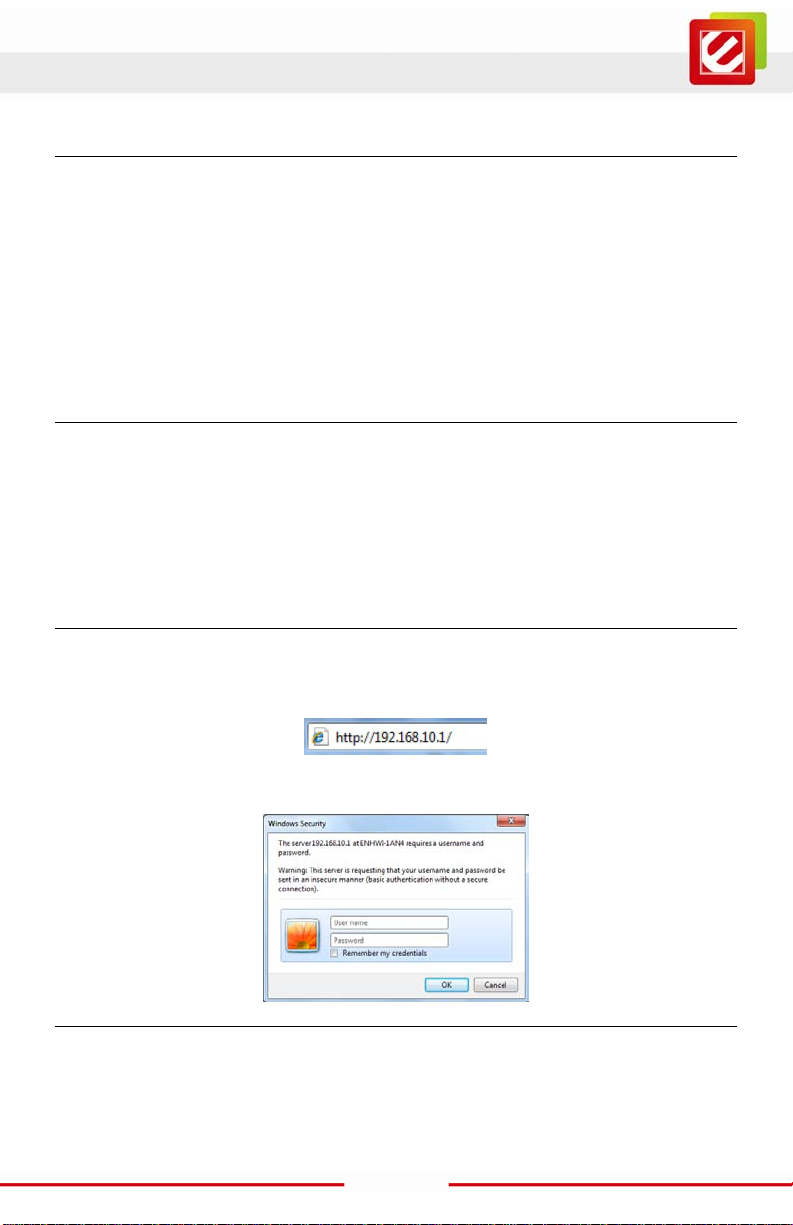
1. Open the Internet browser.
2. Enter IP address http://192.168.10.1 (the factory-defaul t IP address setting) to the
URL web address location.
3. When the following dialog box appears, enter the user name and password to logi n
to the main configuration window, the default username and password i s “admin”.
Setup Wizard
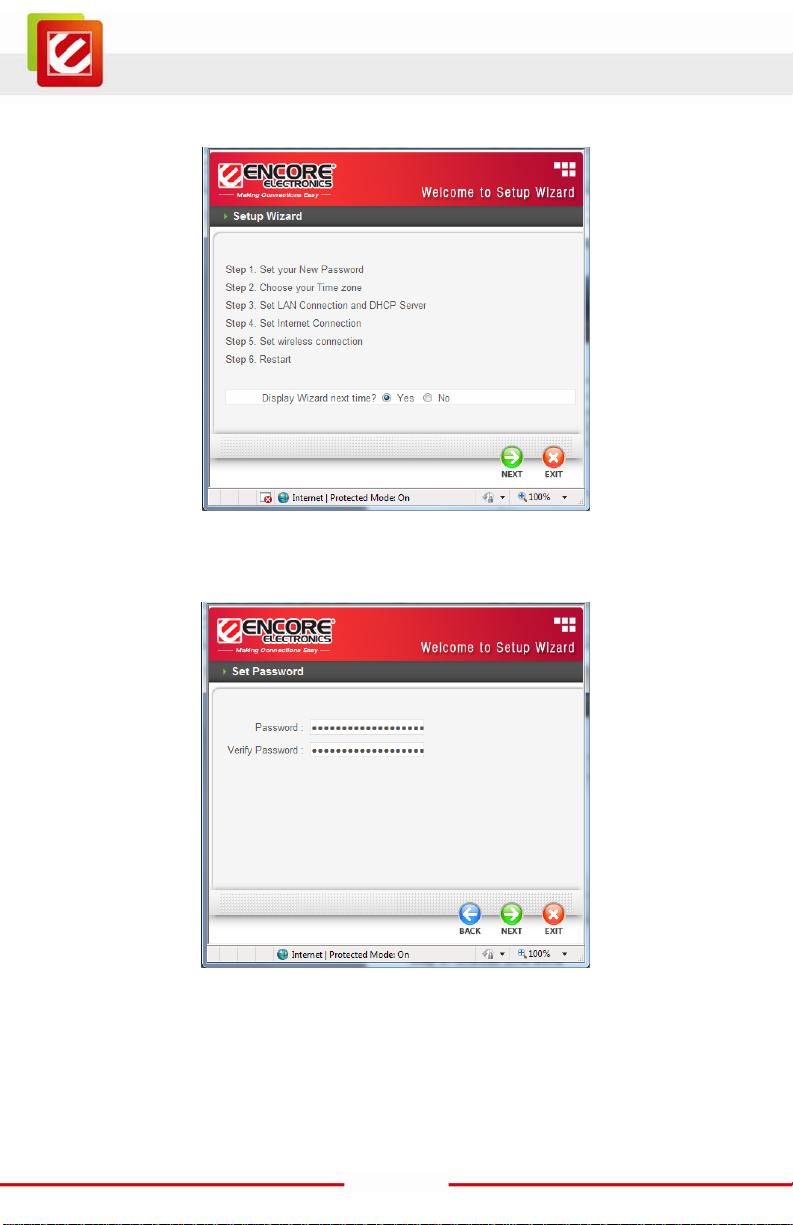
Setup wizard is provided as part of the web configuration util ity. User can simply follow the
step-by-step proc ess to get the wireless Router configuration ready to run in 6 easy steps
by clicking on the “Wizard” button on the function menu. The following sc reen will appear.
12
Page 14
www.encore-usa.com
Please click “Next” to continue.
Step 1: Set your new password
Setting the new admin password of the W LAN R outer. Please click “Next” to continue.
Step 2: Choose time zone
Select the time zone from the drop down li st. Please click “Next” to continue.
13
Page 15
www.encore-usa.com
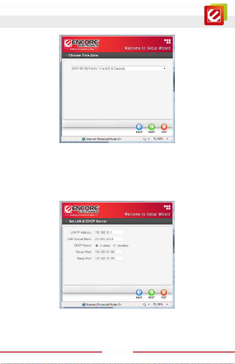
Step 3: Set LAN connecti on and DHCP server
Set user ’s IP address and mask. The default IP is 192.168.10.1. If the user chooses to
enable DHCP, please click “Enable”. DHCP enabled is able to automatically assign IP
addresses. Please assign the range of IP addresses in the fields of “Range start” and
“Range end”. Please click “Next” t o continue.
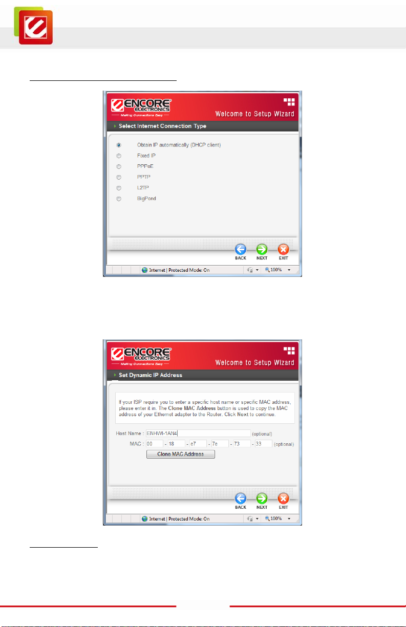
Step 4: Set Internet con nection
The WLAN Router wi ll attempt to auto detect your Internet Connection.
14
Page 16
www.encore-usa.com
Obtain IP automaticall y (DHCP client):
If the user has enabled DHCP server, choose "Obtain IP automatically (DHCP client)" to
have the WLAN Rout er assign IP addresses automatically.
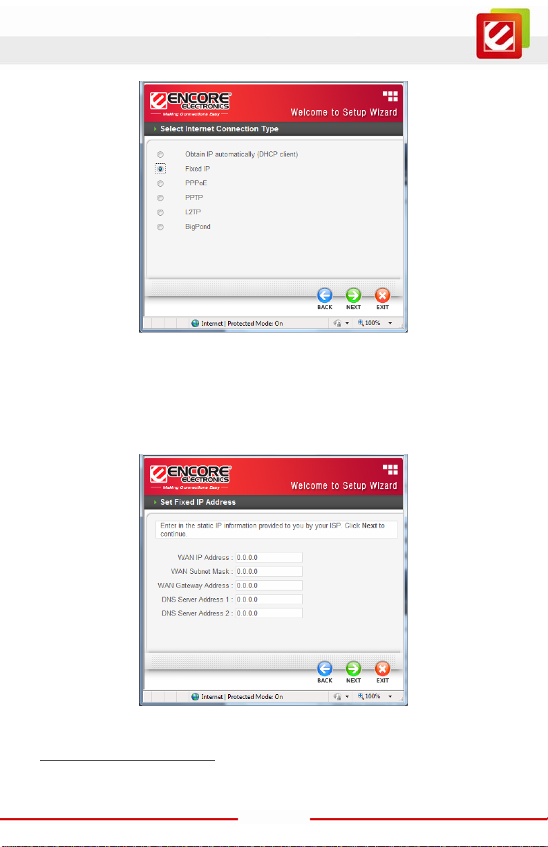
Fixed IP Address:
15
Page 17
www.encore-usa.com
If the Internet S ervice Provider (ISP) assigns a fixed IP address, choose this option and
enter the assigned WAN I P Address, WAN Subnet Mask, WAN Gateway Address and
DNS Server Addresses for the WLAN Router.
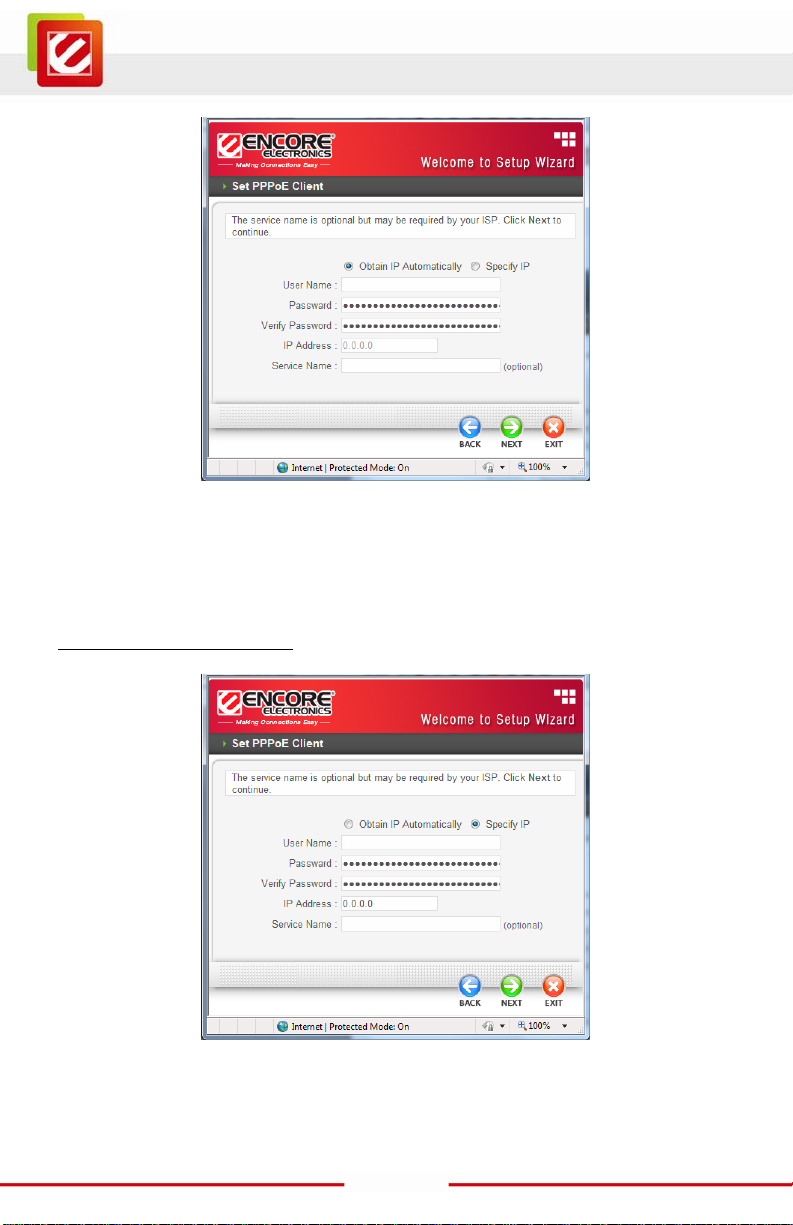
PPPoE to obtain IP automatically:
16
Page 18
www.encore-usa.com
If connected to the I nternet using a PPPoE (Dial-up xDSL) connection, and the ISP
provides a User Name and Password, then choose this option and enter the required
information.
PPPoE with a fixed IP addres s:
If connected to the I nternet using a PPPoE (Dial-up xDSL) connection and the ISP
17
Page 19
www.encore-usa.com
provides a User Name, Password and a Fixed IP Address, choose this option and ent er
the required information.
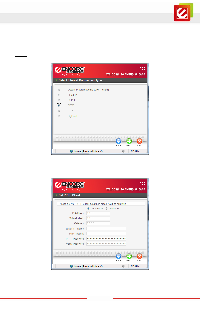
PPTP:
If connected to the I nternet using a PPTP xDSL connection, enter your IP, Subnet Mask,
Gateway, Server IP, PPTP Account and PPTP Password.
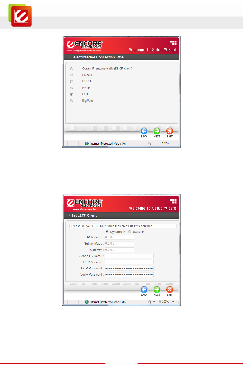
L2TP:
18
Page 20
www.encore-usa.com
If connected to the I nternet using a L2TP (Dial-up xDSL) connection and the ISP provide a
Server IP, Account and Password information, choose this option and enter the req uired
information.
19
Page 21

www.encore-usa.com
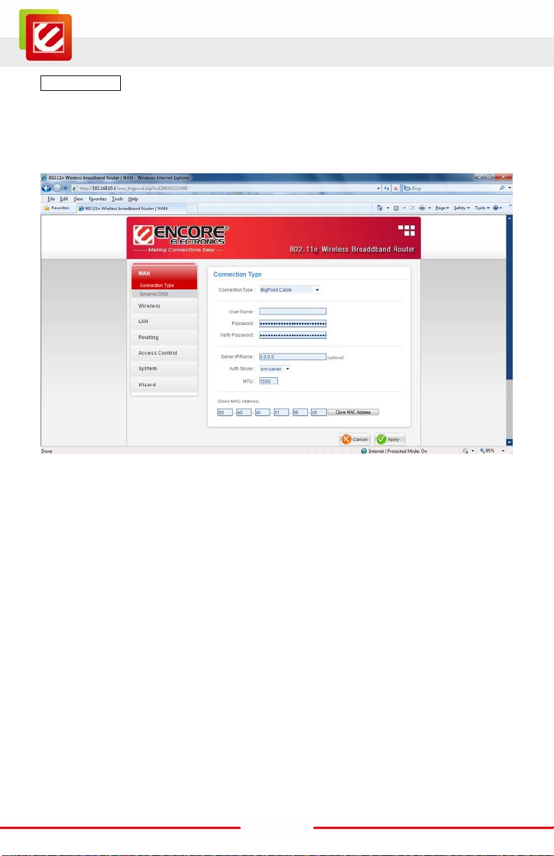
BigPond Cable (Australia):
If your ISP is BigPond Cable, the ISP will provi de a U ser Name, Password, Authentication
Server and Login Server IP (Optional). Choose this option and enter the required
information.
20
Page 22

www.encore-usa.com
Step 5: Set Wireless LAN con nection
Click “Enable” to enable Wireless LAN. If user enables the Wireless LAN, type the SSID in
the text box and select a communicati ons channel. The SSID and channel must be the
same as wireless devices attempting to connect to the WLA N Router.
Step 6: Setup completed
The Setup wizard is now completed. The new settings will be effect ive after the WLAN
Router restarts. Pl ease click “Restart” to reboot the WLAN Router. If user does not want to
make any changes, pl ease click “Exit” to quit without any changes. User also can go back
to modify the setting by clicking “Back”.
21
Page 23

www.encore-usa.com
Advanced configuration
WAN
This screen enables users to set up the WLAN Router WAN connection, specify the IP
address for the WAN, add DNS numbers, and enter the MAC address.
Connection Type
Select the connection type, either DHCP client, Fixed IP, PPPoE, PPTP, L2TP or Bi gP ond
Cable from the drop-down list.
DHCP Client or Fixed IP
If user has enabled DHC P s erver, choose "Obtain IP automatically (DHCP client)" to have
the router assign IP addresses automatically.
22
Page 24

www.encore-usa.com
WAN IP Address: Select whether user wants to specif y an IP address manually, or want
DHCP to obtain an IP address automat ically. When Specify IP is selected, type the IP
address, subnet m ask, and default gatew ay in the text boxes. User’s ISP will provide with
this information.
IP Address: For the Specify mode, enter the specific IP address that provided by your ISP.
Subnet Mask: For the Specify mode, enter the specific subnet mask that provided by your
ISP.
Gateway: For the Specify mode, enter the spec ific gateway IP address that provided by
your ISP.
DNS 1/2: Manually specific DNS server IP address; For the Obtain IP Automatically mode,
if enter 0.0.0.0 in this filed, the DHCP server will provides DNS server automatically.
Clone MAC Address: If your ISP requires you to enter a speci fic MAC address, please
enter it in. The Clone MAC Address button is used to copy the M AC address of your
Ethernet adapter to the Router.
23
Page 25

www.encore-usa.com
PPPoE
If connected to the I nternet using a PPPoE (Dial-up xDSL) Modem, the ISP will provide a
Password and User Nam e, and then the ISP uses PPPoE . Choose this opt ion and enter
the required information.
WAN IP: Select the WAN IP address Obtain from ISP automatic all y or enter the specified
IP address.
Server Name: Enter the server name provided by ISP (optional).
User Name: Enter the user name provided by ISP.
Password: Enter the password provided by ISP.
Retype Password: Enter the password again.
DNS: Enter the IP address of specified DNS s erver here, default value 0.0.0.0 is get t he
DNS settings from ISP.
Auto-reconnect: Select the connection type for Always-on, Manual or Connect-on
Demand connecting.
Idle Time Out: Enter the idle time out for Connect on Daemon, when no Internet access
during the idle tim e, the PPPoE connection will auto disconnect.
MTU: Enter the specified MTU (Maximum Transmission Unit). The default value is 1492 bytes.
24
Page 26

www.encore-usa.com
PPTP/L2TP with Dynamic IP
If connected to the Internet using a PPTP/L2TP (Dial-up xDSL) with dynamic IP
connection, enter the your Serv er IP, PPTP/L2 TP Account and PPTP/L2TP Pass word, if
your ISP has provided yo u with a DNS IP address, enter it in the DNS field, otherwise,
leave it zero.
25
Page 27

www.encore-usa.com
PPTP/L2TP with Static IP
If connected to the I nternet using a P PTP/L2TP (Di al-up xDSL) wi th static IP connection,
enter the your IP Address, Subnet Mask, Gateway IP address, DNS IP address, Server IP
address, PPTP Account and PPTP Password.
26
Page 28
www.encore-usa.com
BigPond Cable
If your ISP is Big Pond Cable, the ISP will provide a User Name, Password, Authentication
Server and Login Server IP (Optional). Choose this option and enter the required
information.
27
Page 29
www.encore-usa.com
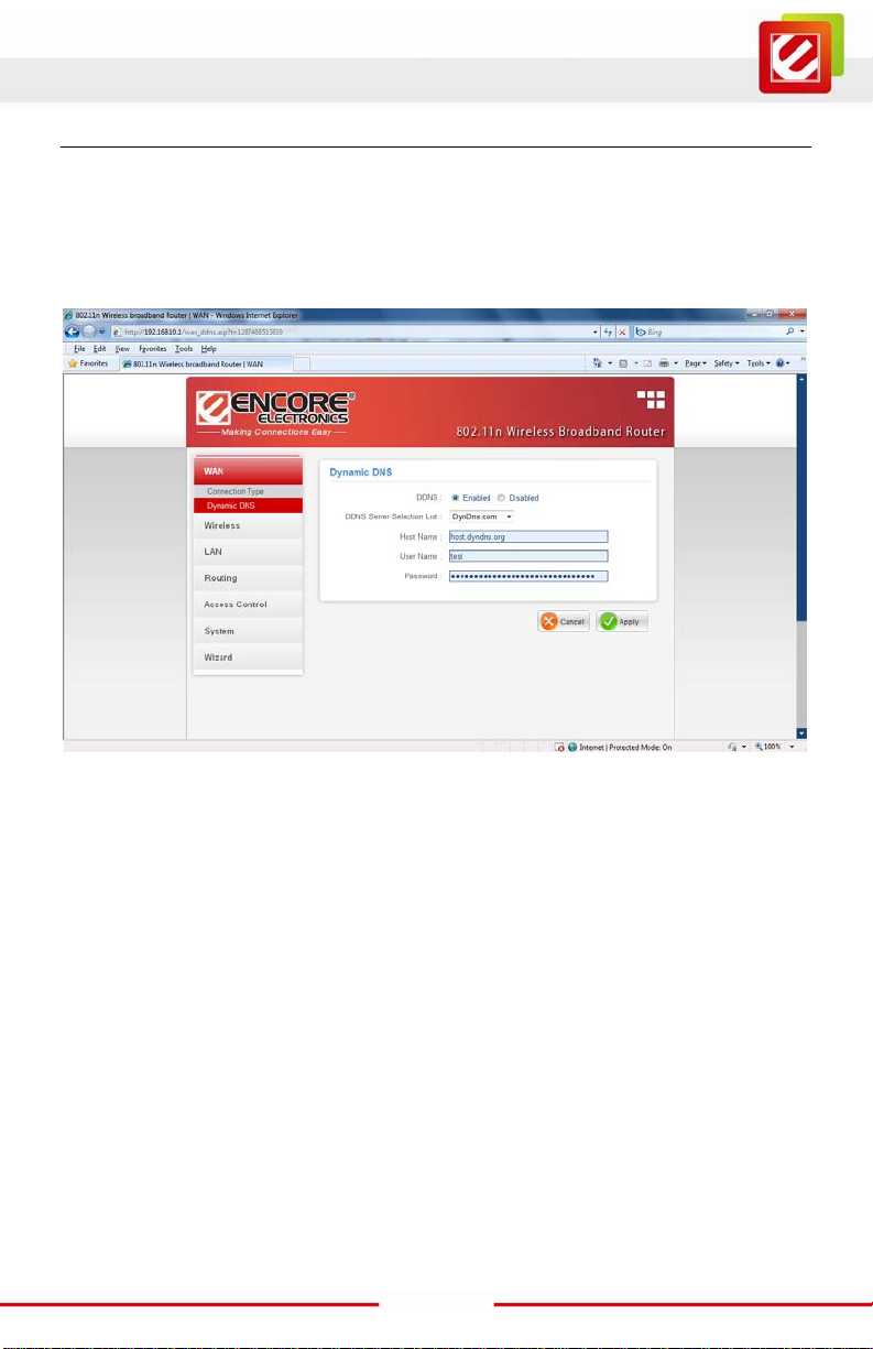
Dynamic DNS
This synchronizes the DDNS server wi th your current Public IP address when you are
online. First, you need to register your preferred DNS wi th the DDNS provider. Then,
please select the DDNS address in the Server Address and fill the related inf ormation in
the below fields: H ost Name, User Name and Password.
28
Page 30

www.encore-usa.com
Wireless
This section enables users to configuration the wireless communications parameters for
the WLAN Router.
Basic
This page allow user to enable and disable the wireless LAN func tion, create a SSID, and
select the channel f or wireless communications.
Enable/Disable: Enables or disables wireless LAN.
SSID: Type an SSID in the text box. The SSID of any wireless device must match the
SSID typed here in order for the wireless device to access the LAN and WAN via the
WLAN Router.
SSID Broadcast: While SSID Broadcast is enabled, all wireless clients will be able to view
the WLAN Router’s SSID.
Channel: Select a transmission c hannel for wireless communications. The channel of any
wireless device must match the channel selected here in order for the wirel ess device to
access the LAN and WAN via the WLAN Router.
29
Page 31

www.encore-usa.com
Security
Authentication Type: The authentication type default is set to open system.
There are four optio ns: WEP , WPA, WPA2 and WPA2-Auto.
WEP: Open System and Shared Key requires the user to set a WEP key to exchange data
with other wirel ess clients that have the same WEP key.
30
Page 32

www.encore-usa.com
WEP Key Format: Select the ASCII or HEX
WEP Key Length: Select the WLAN Router supports, 64 and 128-bit encryption.
Key Length Hex ASCII
Type characters 0-9, A-F, a-f alphanumeric format
64-bit 10 characters 5 characters
128-bit 26 characters 13 characters
Key 1: Enables users to create WEP keys with W PS enabled. Manually enter a set of
values for Key 1.
Note: Key 1 ~ Key 4: Enables users to create up to 4 different WEP keys with
WPS disabled. M anually enter a set of values for each key. Select a key to use by
clicking the radio button next to the key.
WPA/WPA2/WPA-Auto Security with EAP
If WPA, WPA2 or WPA2-Auto EAP is sel ected, the above scr een is shown.
Please set the length of the encryption key and the parameters for the RADIUS server.
Encryption Type: Select the encrypti on type for TKIP, AES or AUTO encryption.
Note: TKIP is available for B or G W LAN Band only.
The WLAN Band sett ing is under Wireless/Advanced.
31
Page 33

www.encore-usa.com
RADIUS Server 1: Enter the IP address, Por t used and Shared Secret by the Radius
Server 1.
WPA/WPA2/WPA2-Auto Security with PSK
If WPA, WPA2 or WPA2-Auto PSK is selected, the above screen is shown.
Encryption Type: Select the encryption type for TKIP , AES or AUTO encryption.
Note: TKIP is available for B or G W LAN Band only.
The WLAN Band sett ing is under Wireless/Advanced.
Passphrase: The length should be 8 charac ters at least.
32
Page 34

www.encore-usa.com
Advanced
This screen enables users to configure advanced wireless functions.
Beacon Interval: Type the beacon interval in the text box. User can specify a value from
25 to 1000. The default beacon interval is 100.
RTS Threshold: Type the RTS (Request-To-Send) threshold in the text box. This value
stabilizes data flow. If data flow is irregular, choose values between 256 and 2346 until
data flow is normalized.
Fragmentation Threshold: Type the fragmentation threshold in the text box. If packet
transfer error rates are high, choos e values between 1500 and 2346 until packet tr ansfer
rates are minim ized. (NOTE: set thi s fragmentation threshold value may diminis h system
performance.)
DTIM Interval: Type a DTIM (Delivery Traffic Indication Mess age) interval in the t ext box.
User can specify
33
Page 35

www.encore-usa.com
Wi-Fi Protected Setup
This screen enables users to configure the Wi-Fi Protec ted Setup function.
WPS: Enable or Disabl e the WPS (Wi-Fi Protected Setup) func tion
Status: Display the status (Un-configured State/Configured State) information of WPS.
Self-PIN Number: Display the current PIN number of the W LAN Rout er.
Client PIN Number: Type Client’s PIN number the c lient uses to negotiate with the WLAN
Router via WPS connection. It is only us ed when users want their station to join Router's
network.
Push Button Configuration: Clicking the Start PBC button will invoke the Push Button
Configuration (PBC) method of W PS. P ush the WPS button on the client side when users
want their stati on to join Router’s network.
34
Page 36

www.encore-usa.com
LAN
This page allows the user to configure LAN and DHCP properties, such as the host name,
IP address, and subnet m ask.
Basic
Host Name: Type the host name in the text box. The host name is required by some ISPs.
The default host name is "Encore".
IP Address: This is the IP address of the WLAN Router. The default IP address is
192.168.10.1.
Subnet Mask: Type the subnet mask for t he WLAN Router in the text box. The default
subnet mask is 255. 255.255.0.
DHCP
Enable the DHCP server to allow the WLAN Rout er to automatically assign IP addresses
to devices connecting to the LAN. DHCP is enabled by default.
All DHCP client comput ers are listed in the table at the bottom of the screen, providing the
host name, IP address , and MAC address of the client.
Start IP: Type an IP address to serve as the start of the I P range that DHCP will use to
assign IP addresses to all LAN devices connec ted to the WLAN Router.
35
Page 37

www.encore-usa.com
End IP: Type an IP address to serve as the end of the IP range that DHCP will use t o
assign IP addresses to all LAN devices connec ted to the WLAN Router.
Lease Time: The lease time specifies the amount of connection time a network user be
allowed with their current dynamic IP address.
Routing
This page allows the user to setup Static or Dynamic routing
Static
Network Address: Enter the target IP address in the textbox.
Network Mask: Enter the subnet mask in the textbox.
Gateway Address: Enter the gateway IP address i n the textbox.
Interface: Select “LAN” or “WAN” from drop-down list.
Metric: Enter the number of ‘hops’ in the textbox; nor m ally you can set the value to ‘0’.
Click the “Add” button to save the settings.
36
Page 38

www.encore-usa.com
Dynamic
Dynamic routing is a technique developed to automatically adjust routing tables in the
event of network fai lures. The most common dynamic rout ing protocols is RIP (Routing
Information Protocol), which is very common on small networks.
Routing Table
This page provides a routing table.
37
Page 39

www.encore-usa.com
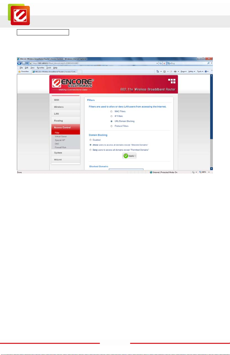
Access Control
This page enables you to define access r estrictions, set up pr otocol and IP filters, create
virtual server s, define access f or special applications such as games, and s et firewall
rules.
Filters
Using filters to deny or allow the users to access to the internet. Four types of filters can be
select: MAC, IP, URL/Domain Blocking, and Protocol Filters.
38
Page 40

www.encore-usa.com
MAC Filters
MAC Filter: Enables you t o allow or deny accessing the internet .
Disable: Disabl e the MAC filter func tion.
Allow: Only allow computers with MAC address list ed in the MAC Table.
Deny: Computers in the MAC Table are denied Internet access.
MAC Table: Use this section to create a user profile which internet access is denied or
allowed. The user profiles are listed i n the table at the bottom of the page.
(Note: Click anywhere in the item. Onc e the line is selected, the fields automatically load
the item's parameters, which you can edit .)
Name: Type the name of the user to be permitted/denied access.
MAC Address: Type the MAC address of the user's network interface.
Add: Cl ick to add the user to the list at the bottom of the page.
Update: Click to update information for the user, if you have changed any of the f ields.
Delete: Select a user from the table at the bott om of the list and click Delete to remove
the user profil e.
Cancel: Click Cancel to erase all fields and enter new i nformation.
39
Page 41

www.encore-usa.com
IP Filter
Type the IP range. IP addresses falling between this value and the R ange End are not
allowed to access the Internet.
Add: Click to add t he IP range to the table at the bottom of the screen.
Update: Cli ck to updat e inf or ma ti on for t he range i f you ha ve s el ect ed a l is t item
and have made changes.
Delete: Select a list item and click Delete to rem ove the item from the l ist.
Cancel: Click the Cancel button to eras e all fields and enter new information.
40
Page 42
www.encore-usa.com
URL/Domain Blocking
Y ou could specify the domains that allow users to access or deny by clicking one of the two
items. Also, add the specif ied domains in the text box.
Disable: Disable the Domain/URL Blocking function.
Allow: Allow users to access all domains except “Blocked Dom ains”.
Deny: Deny users to access all domains except “Permitted Domains”.
41
Page 43

www.encore-usa.com
Blocked Domains: List Dom ain/URL you will Denied or Allowed.
Delete: Select a Domain/ URL from the table at the bottom of the list and cli ck
Delete to remove the D om ain/URL.
Add: Click to Add button to add domain to the Blocked Domains.
Cancel: Click the Cancel button to eras e all fields and enter new information.
42
Page 44

www.encore-usa.com
Protocol Filters
This screen enables you to define a minimum and maximum IP address range filter; all IP
addresses falling within the range ar e not allowed acc essing internet. The IP filter profiles
are listed in the table at the bottom of the page. ( N ote: Click anywhere in the item. Once
the line is selec ted, the fields automatically load the item's parameters, which you can
edit.)
Enable: Click to enable or disable the IP address filter.
Name: Type the name of the user to be denied access.
Protocol: Select a protocol (TCP or UDP) to use for the virtual server.
Port: Type the port range of the protocol.
43
Page 45
www.encore-usa.com
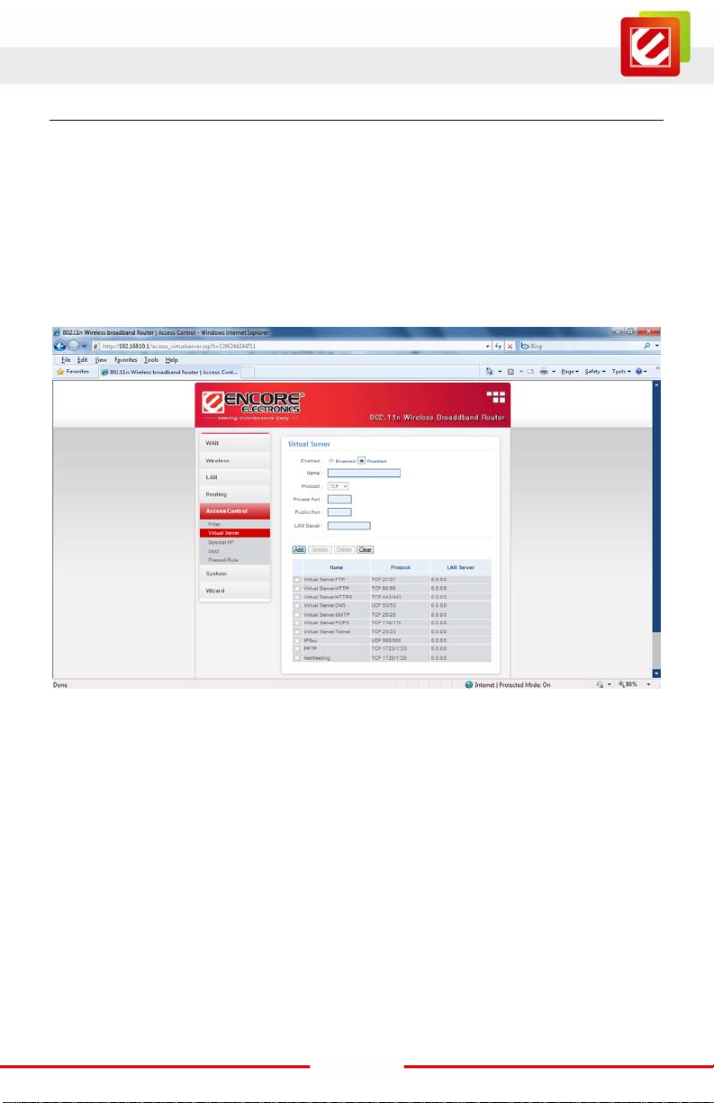
Virtual Server
This screen enables user to create a virtual server via the WLAN Router. If the WLAN
Router is set as a virtual server, remote users requesting Web or FTP services through the
WAN are directed to local servers in the LAN. The WLAN R outer redirects the request via
the protocol and port numbers to the correct LAN server. The Virtual Sever profiles are
listed in the table at the bottom of the page.
Note: When selecting items in the table at the bottom, click anywhere in the item. The line
is selected, and t he fields automatically load the item 's parameters, which user can edit.
Enable: Click to enable or disable the virtual server.
Name: Type a descriptive name for t he virtual server.
Protocol: Select a protocol (TCP or UDP) to use for the virtual server.
Private Port: Type the port number of the c om puter on the LAN that i s being used to act
as a virtual server.
Public Port: Type the port number on the WAN that w il l be used to provide acc ess to the
virtual server.
LAN Server: Type the LAN IP address that will be assigned to the virtual server.
Add: Click to add t he virtual server to the table at the bottom of the screen.
Update: Clic k to update information for the vi rtual server if the user has selected
a listed item and has made changes.
44
Page 46
www.encore-usa.com
Delete: Select a listed item and click Delete to remove the item from the list.
Cancel: Click Cancel button to erase all fields and enter new information.
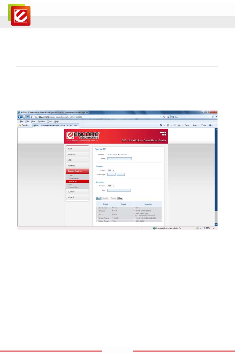
Special AP
This screen enables users to specif y special applicati ons, such as games whic h require
multiple connections that are blocked by NAT. The special applications profiles are listed in
the table at the bottom of the page.
Note: When selecting items in the table at the bottom, click anywhere in the item. The line
is selected, and t he fields automatically load the item's parameters, whic h user can edit.
Enable: Click to enable or disable the application profile. When enabled, users will be able
to connect to the appl ication via the W LA N Router’s WAN connect ion. Click “Disabled” on
a profile to prevent users from accessing the application on the WAN connection.
Name: Type a descriptive name for t he application.
Trigger: Defines the outgoing communication that determines whether t he user has
legitimate access to the applicati on.
Protocol: S elect the protocol (TCP, UDP, or * for TCP+UDP) that can be used to
access the application.
Port Range: Type the port range t hat can be used to acc ess the applicat ion in
the text boxes.
45
Page 47
www.encore-usa.com
Incoming: Defines which incoming communications users are permitted to connect with.
Protocol: Select the protocol (TCP, UDP, or * for TCP+UDP) that can be used by
the incoming communication.
Port: Type the port number that can be used for the i ncoming communicat ion.
Add: Cli ck to add the spec ial applic ation prof ile to the table at the bottom of the
screen.
Update: Click to update information for the special application if user have
selected a list item and have made changes .
Delete: Select a list item and click Delete to remove the item from t he list.
Cancel: Click Cancel button to erase all fields and enter new information.
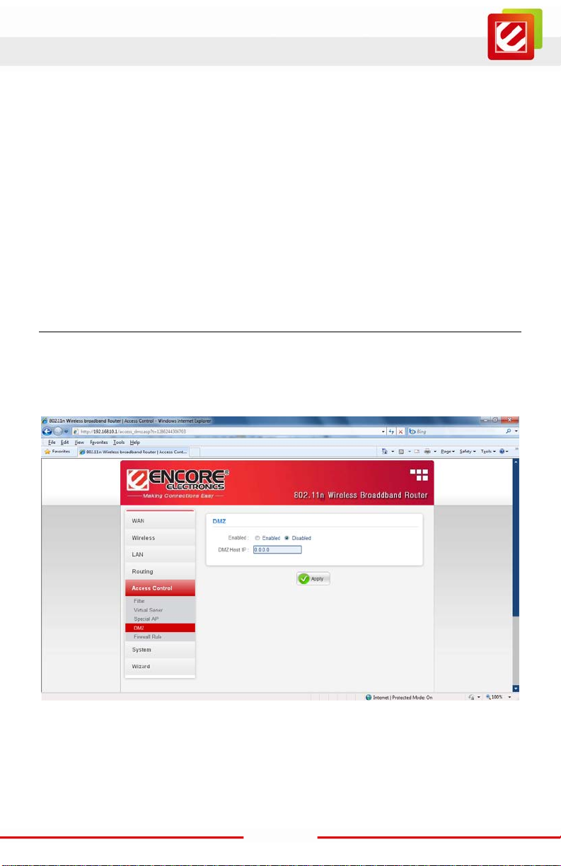
DMZ
This screen enables users to create a DMZ for those computers that cannot access
Internet applic ations properly through the WLAN Rout er and associated sec urity settings.
Note: Any clients added to the DMZ exposes the clients to security risks such as viruses
and unauthorized access.
Enable: Click to enable or disable the DMZ.
DMZ Host IP: Type a host IP address for the DMZ. The computer with this IP address acts
as a DMZ host with unlimited Internet ac cess.
Apply: Click to save the settings.
46
Page 48
www.encore-usa.com
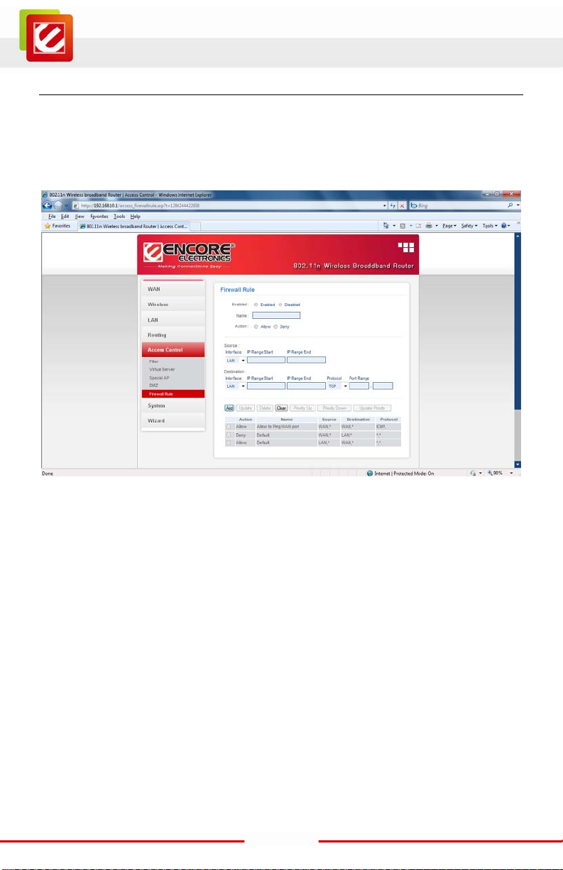
Firewall Rule
This screen enables users to set up the firewall. The WLAN Router provides basic firewall
functions, by f iltering all the packets that enter the WLAN Router using a set of rules. The
rules are list ed in sequential order--the lower the rule number, the higher the priority the
rule has.
Enable: Click to enable or disable the firewall rule profile.
Name: Type a descriptive name for t he firewall rule prof ile.
Action: Select whether to Allow or Deny packets that conform to the rule.
Source: Defines the source of the incoming packet that the rule i s applied to.
● Interface: Select which interface (WAN or LAN) the rule is applied to.
● IP Range Start: Type the start IP addr ess that the rule is applied to.
● IP Range End: Type the end IP address that the rule is applied to.
Destination: Defines the destination of the incoming packet that the rule i s applied to.
● Interface: Select which interface (WAN or LAN) the rule is applied to.
● IP Range Start: Type the start IP addr ess that the rule is applied to.
● IP Range End: Type the end IP address that the rule is applied to.
● Protocol: Select the protocol (TCP, UDP, or ICMP ) of the destination.
● Port Range: Select the port range.
47
Page 49

www.encore-usa.com
Add: Cl ick to add the rule profile to the table at the bottom of the screen.
Update: Click to update information for the rule if the user has selected a listed item and
has made changes.
Delete: Select a listed item and click Delete button to r emove the entry from the list.
Clear: Click “Clear” to eras e all fields and enter new i nformation.
Priority Up: Select a rule from the list and click “Priority Up” to increase the priority of the
rule.
Priority Down: Select a rule from the list and click “Priority Down” to decrease the
priority of the rule.
Update Priority: After increasing or decreasing the priority of a rule, click “Update
Priority” to save the changes.
48
Page 50

www.encore-usa.com
System
This selection enabl es users to view the status of the WLAN Router LA N, WAN and
Wireless connec tions, and view logs and statistics pertai ning to connections and packet
transfers.
Password
This screen enables users to set administrative and user passwords. These passwords
are used to gain access to the WLAN Router interface.
Administrator: Type the password the Administrator will use to log into the system. The
password must be typed again for confir m ation. The Administrator can also authorize
users the abili ty to configure the WLAN Router.
User: Type the password the User wil l use to log in to the syst em . The password must be
typed again for confirmation.
49
Page 51

www.encore-usa.com
Time
This screen enables users to set the time and date for the WLAN Router's real -time clock,
select properly time zone, and enable or disable daylight saving.
Local Time: Displays the local time and date.
Time Zone: Select the tim e zone from the drop-down list.
Synchronize the clock with NTP server: Enables or Disable the system time from NTP
Server.
Manually Date and Tim e S etting: After you disabled synchronize the clock with NTP
server, manually setting the WLAN Router system time, and then press the Set Computer
Time button to update the system time.
Daylight Saving: Enables or Disable dayl ig ht savi ng t ime. W hen ena bl ed, s elec t the s tart
and end date for dayli ght saving time.
50
Page 52

www.encore-usa.com
Device Informati o n
This screen enables users to view the WLAN Router ’s LAN, Wireless and WAN
configurations.
WAN: This section dis plays the WAN interface conf iguration including the MAC address,
Connection status, DHCP client status, IP address, Subnet mask, Default gateway, and
DNS.
Wireless: This sect ion displays the wireless configuration information, i ncluding the MAC
address, the Connection status, SSID, Channel and Authentication type.
LAN: This section displays the LAN interface configuration includi ng the MAC address, IP
Address, Subnet Mask, and DHCP Server Status. Click “D H C P Table” to view a list of
client stations currently connec ted to the WLAN Router LAN interface.
Click “DHCP Release” to release all IP addresses assigned to client s tations connected to
the WAN via the WLAN Router. Click “DHCP Renew” to reassi gn IP addresses to client
stations connected to the WAN.
51
Page 53
www.encore-usa.com
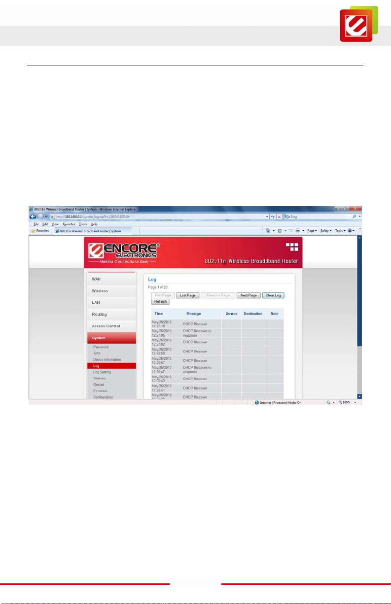
Log
This screen enables users to view a runni ng log of Router sys tem statistics, events, and
activities. The log displays up to 200 entries. Older entries are overwritten by new entries.
The Log screen comm ands are as follows :
Click “First Page” to view the first page of the log
Click “Last Page” to view the final page of the log
Click “Previous Page” to view the page just before the current page
Click “Next Page” to view the page just after the current page
Click “Clear Log” to delete the contents of the log and begin a new log
Click “Refresh” to renew log s tatistics
Time: Displays the t ime and date that the log entry was created.
Message: Displays summary inform ation about the log entry.
52
Page 54

www.encore-usa.com
Log Setting
This screen enables users to set Router Log parameters.
SMTP Authentication: Sel ected the Enabled if the SMTP server need for authentication,
fill in account nam e and password in SMTP Account field and SMTP Password field.
SMTP Account: If the SMTP Authentication enabled, fill in the SMTP account name here.
SMTP Password: If the SMTP Authentication enabled, fill in the password of the SMTP
account here.
SMTP Server / IP Address: Type your SMTP server address here.
Send From: Type an email address for the log to be sent from.
Send to: Type an email address for the log to be sent to. Click “Email Log Now” to
immediately send the current log.
E-mail Logs: Email the logs to specified email receiver.
When log is full - The time is not fixed. The log will be sent w hen the log is full,
which will depend on the volume of traffic.
Every day, Every Monday ... - The log is sent on the interval specified.
If "Every day" is sel ected, the log is sent at the time specifi ed.
I f t he day i s s pec ifi ed, t he l og is sent once per week , on the s pe ci f ied
day.
Select the time of day you wi sh the E-mail to be sent.
If the log is full before the time specified to send it, it will be sent
regardless.
53
Page 55

www.encore-usa.com
Syslog Server: Type the IP address of the S yslog Server if user wants the WLAN Router
to listen and receive incoming Sysl og m essages.
Log Type: Enables users to select what items will be included in the log:
System Activity: Dis plays information related to WLAN Router operation.
Debug Information: Displays information related to errors and system
malfunctions.
Attacks: Displ ays information about any malicious activity on the network .
Dropped Packets: Displays about packets that have not been transferred
successfully.
Notice: Displ ays important notices by the system admi nistrator.
Statistic
This screen displays a table that shows the rate of packet trans m ission via the WLAN
Router’s LA N , Wireless and WAN ports (in bytes per second).
Click “Reset” to erase all statistics and begin logging statistics again.
54
Page 56

www.encore-usa.com
Restart
Click “Restart” t o restart the system in the event the system is not performing cor rectly.
55
Page 57

www.encore-usa.com
Firmware
This screen enables users to keep the WLAN Router firmware up to date.
Please follow the bel ow instructions:
Download the latest firmware from t he Encore’s web site, and save it to disk.
Click “Browse” and go to the location of the downloaded fir m w are file.
Select the fil e and click “Upgrade” to update t he firmware to the l atest release.
56
Page 58

www.encore-usa.com
Configuration
This page provided us ers to save and load different settings as profiles, restor e factory
default settings.
Save Settings: Click the “Save” button to back up your configuration setting.
Load Settings: Click the “Browse” button to find your bac k up settings file, and then click
the “Open” button. Then, click the “Load” button to restore your configuration settings on
this screen.
Restore Factory Default Settings: Click this button for restore to factory default settings.
57
Page 59

www.encore-usa.com
UPnP
UPnP is short for Universal Plug and Play that is a networki ng architecture that provides
compatibility among networking equipm ent, software, and peripherals. The WLAN R outer
is an UPnP-enabled Router and will only work with other UPnP devices/software. Select
“Enable” if you want to use thi s UPnP functionality.
58
Page 60
www.encore-usa.com
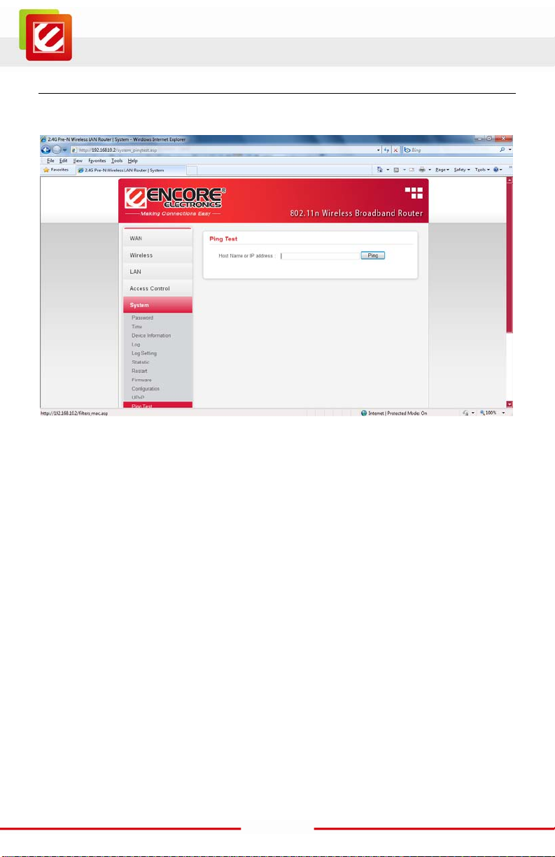
Ping Test
The ping test enables users to determine w hether an IP address or hos t is present on the
Internet. Type the host name or IP addres s in the text box and click Ping.
59
Page 61
www.encore-usa.com
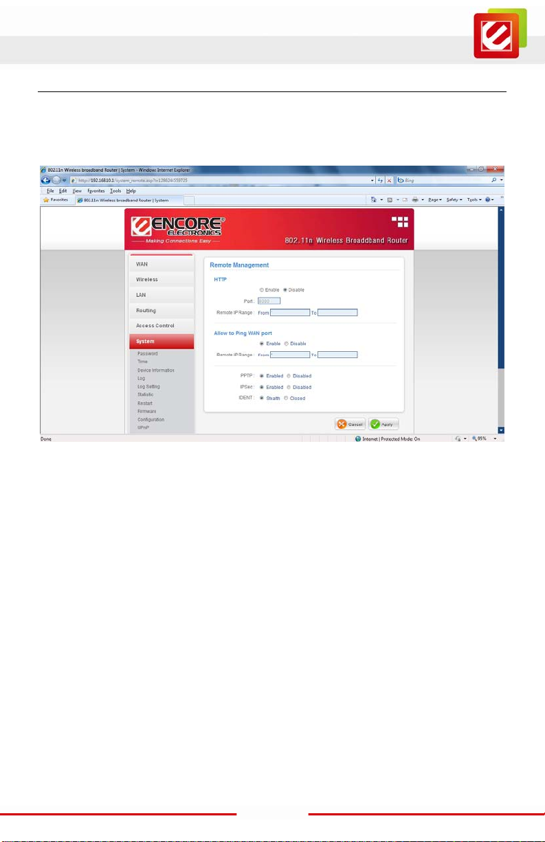
Remote Management
This screen enables users to set up remote management. Using rem ote management, the
WLAN Router can be c onfigured through the WAN vi a a Web br ow ser. A user name and
password are required to perform remote management.
HTTP: Enables users to set up HTTP access of the Port number, and Remote IP Range
for remote managem ent.
Allow to Ping WAN Port: Type a range of Router IP addresses that can be pinged from
remote locations
PPTP: Enables user s to set up PPTP access for remote management.
IPSec: Enables users to set up IPSec ac cess for remote managem ent.
UPnP Enable: UPnP is short for Uni versal Plug and Play t hat is a networking architecture
that provides compatibility among networking equipment, software, and peripherals. The
WLAN Router is an UPnP-enabled Router and will only work with ot her UPnP
devices/software. If user does not want to use the UPnP functionality, select “Disabled” to
disable it.
60
Page 62

www.encore-usa.com
Setting the ENHWI-1AN4 as an Access Point.
1. Connect your Et hernet cable between t he EN HWI-1AN4 router and your main router
which Internet connected with DHCP Server.
2. Login to the ENHWI-1AN4 web based Graphi cal User Interf ace.
3. Disable the "DHCP Server", and then click the "Apply" button.
4. Wait for few second to save change. Please click the “BACK” button if router does not
back to previously screen.
61
Page 63

www.encore-usa.com
5. Disable "NAT", and then click the "A pply" button.
6. Wait for few second to save change. Please click the “BACK” button if router does not
back to previously screen.
62
Page 64

www.encore-usa.com
* Local tech-support numbers are provided in selectively countries. Service may change without prior notice.
Please visit www.encore-usa.com for more details.
Product specifications, size, and shape are subj ect to change w ithout not ice , an d act ual product appearance may differ from t hat dep icted herein.
All trademarks and brand names are the properties of their respective holders.
63
 Loading...