

Page 1
–© 2010 Encore Electronics, Inc. All rights reserved.COVER
© 2010 Encore Electronics, Inc.
Product specifications, size, and shape ar e subject to c hange wi thout notice, and actual product appe arance m ay dif fer from that depic ted herein.
All trademarks and brand names are the properties of their respective holders.
Page 2

1
www.encore-usa.com
TABLE OF CONTENTS
CHAPTER 1 INTRODUCTION.......................................................................2
1.1 SAFETY PRECAUTIONS.....................................................................................2
1.2 LEDS AND INTERFACES....................................................................................2
1.3 PACKAGE CONTENTS........................................................................................4
CHAPTER 2 HARDWARE INSTALLATION................................................5
2.1 CONNECTION WITH NO TELEPHONE SET INSTALLED BEFORE SPLITTER .............5
2.2 CONNECTION WITH TELEPHONE SET INSTALLED BEFORE SPLITTER...................6
CHAPTER 3 SETTING UP THE TCP/IP PROPERTIES..............................7
3.1 SETTING UP THE TCP/IP PROPERTIES...............................................................7
3.1.1 Windows XP............................................................................................7
3.1.2 Windows Vista/7.................................................................................... 10
3.1.3 Linux System..........................................................................................13
3.1.4 Mac System............................................................................................15
3.2 CHECKING THE TCP/IP CONFIGURATION .......................................................16
3.2.1 Windows XP/Vista/7..............................................................................16
3.2.2 Linux System..........................................................................................17
CHAPTER 4 ACCESS THE WEB CONFIGURATION..............................18
4.1 HOW TO ACCESS THE ROUTER .......................................................................18
4.2 WIZARD .........................................................................................................19
4.3 TECHNICAL SUPPORT .....................................................................................28
Product specifications, size, and shape are subject to change without notice, and actual
product appearance may differ from that depicted herein.
All trademarks and brand names are the properties of their respective holders.
© 2010 Encore Electronics, Inc. All rights reserved.
Page 3
2
www.encore-usa.com
Chapter 1 Introduction
This Quick Installation Guide tells you the brief information and steps of configuration of the
ENDSL-4R5G Wireless Router / High Speed ADSL 2+ Modem. If you need more detailed
information, you could find them on the user manual in the CD-ROM came with the product.
1.1 Safety Precautions
Follow the following instructions to prevent the device from risks and damage caused by fire
or electric power:
Use volume labels to mark the type of power.
Use the power adapter packed within the device package.
Pay attention to the power load of the outlet or prolonged lines. An overburden power
outlet or damaged lines and plugs may cause electric shock or fire accident. Check the
power cords regularly. If you find any damage, replace it at once.
Proper space left for heat dissipation is necessary to avoid damage caused by
overheating to the device. The long and thin holes on the device are designed for heat
dissipation to ensure that the device works normally. Do not cover these heat
dissipation holes.
Do not put this device close to a place where a heat source exits or high temperature
occurs. Avoid the device from direct sunshine.
Do not put this device close to a place where it is over damp or watery. Do not spill any
fluid on this device.
Do not connect this device to any computers or electronic products, unless our
customer engineer or your broadband provider instructs you to do this, because any
wrong connection may cause power or fire risk.
Do not place this device on an unstable surface or support.
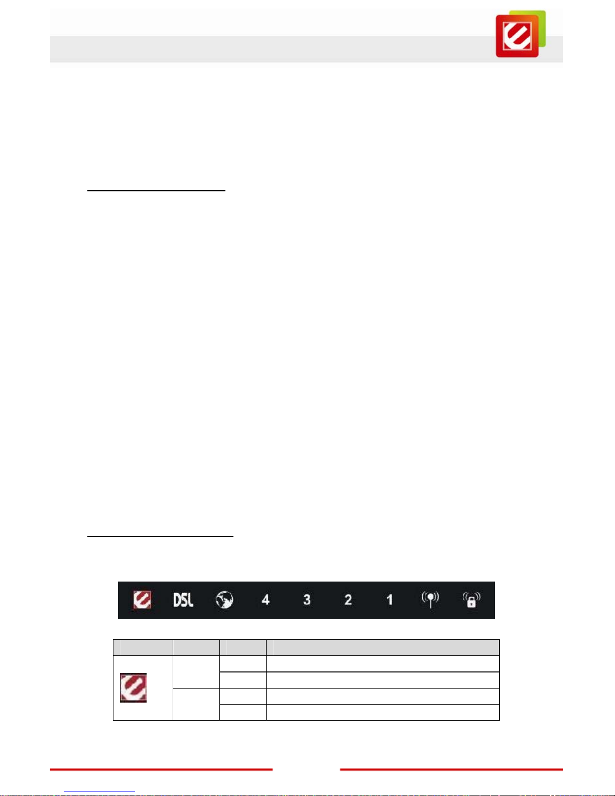
1.2 LEDs and Interfaces
Front Panel
The following table describes the LEDs of the device:
LEDs Color Status Description
On The initialization of the device is successful.
Green
Off The device is powered off.
On The device is self-testing or self-testing is failed.
Red
Blinks The software is upgrading.
Page 4
3
www.encore-usa.com
LEDs Color Status Description
On
Connection between the device and the
physical layer of the office is established.
Slow
Blinks
No signal is being detected.
Green
Fast
Blinks
The device is handshaking with the physical
layer of the office.
On
The Internet connection is normal in the routing
mode (for example: PPP dial-up is successful),
and no Internet data is being transmitted.
Blinks
Internet data is being transmitted in the routing
mode.
Green
Off The device is in the bridge mode.
Red On
The Internet connection fails after successful
synchronization in the routing mode (for
example: PPP dial-up is failed).
On The LAN connection is normal and activated.
Blinks
Data is being transmitted in the LAN or Internet
data is being transmitted in the bridge mode.
4/3/2/1 Green
Off The LAN interface is not connected.
On The WLAN connection has been activated.
Blinks Data is being transmitted in the WLAN.
Green
Off The WLAN connection is not activated.
Blinks
WPS is enabled, and is waiting for client to
negotiate.
Green
Off WPS is disabled.
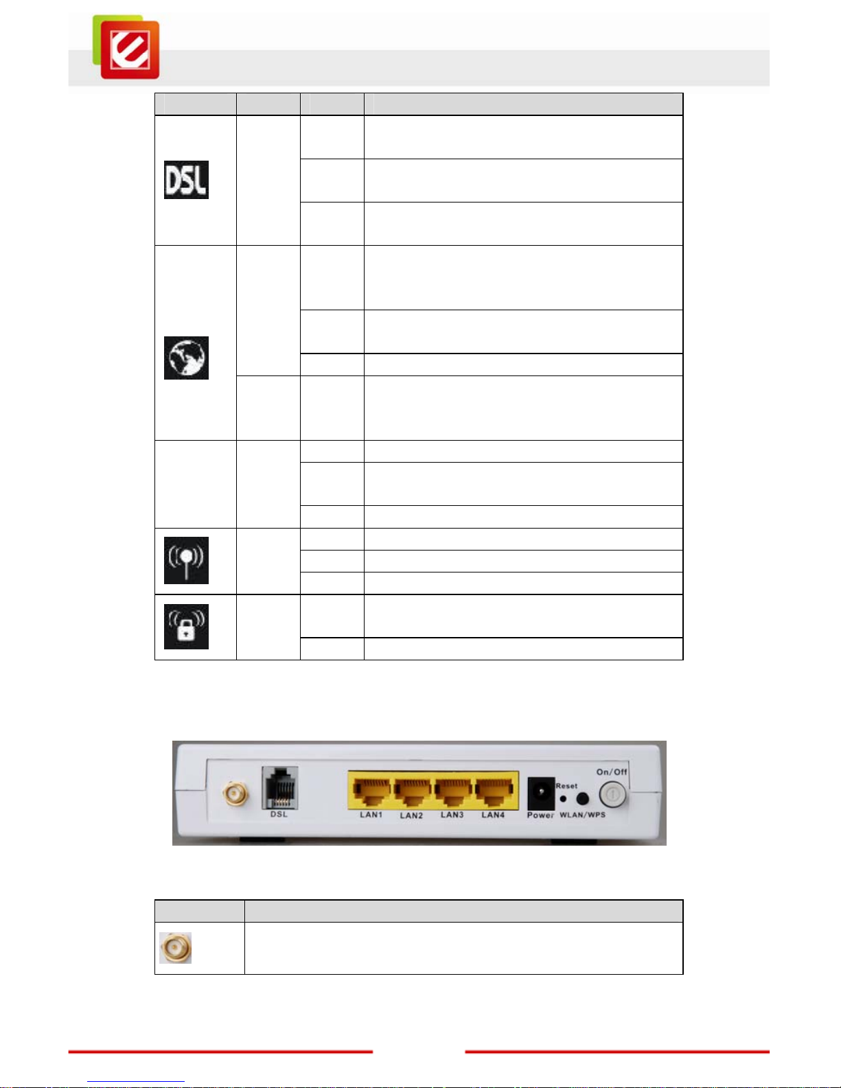
Rear Panel
The following table describes the interfaces of the device:
Interface Description
Wireless antenna.
Page 5
4
www.encore-usa.com
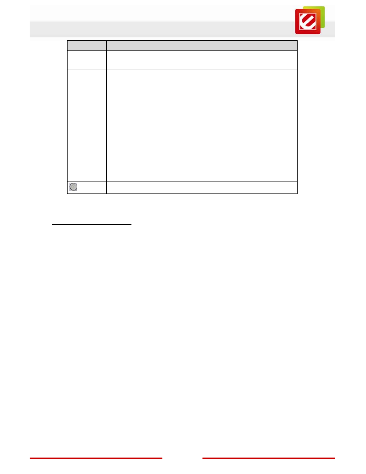
Interface Description
DSL
RJ-11 interface, for connecting to the ADSL interface or a splitter
through a telephone cable.
LAN1/LAN2/
LAN3/LAN4
RJ-45 interface, for connecting to the Ethernet interface of a
computer or the Ethernet devices through an Ethernet cable.
Power
Power interface, for connecting to the power adapter of 12 V DC,
800mA.
Reset
Reset to the factory default configuration. Keep the device powered
on, and insert a needle into the hole for 3 seconds, then release it.
The device is reset to the factory default configuration.
WLAN/WPS
Press the button and hold it for 1 second, to enable WLAN.
Press the button and hold it for 1 second and 3 seconds, it does
not take effect.
Press the button and hold it for 3 or more than 3 seconds, to
initialize WPS negotiation.
Power switch, power on or power off the device.
1.3 Package Contents
One ENDSL-4R5G device
One DC power adapter
One splitter (optiona l)
One QIG (Quick Installation Guide)
One CD-ROM
One RJ-11 cable
One RJ-45 cable
Page 6
5
www.encore-usa.com
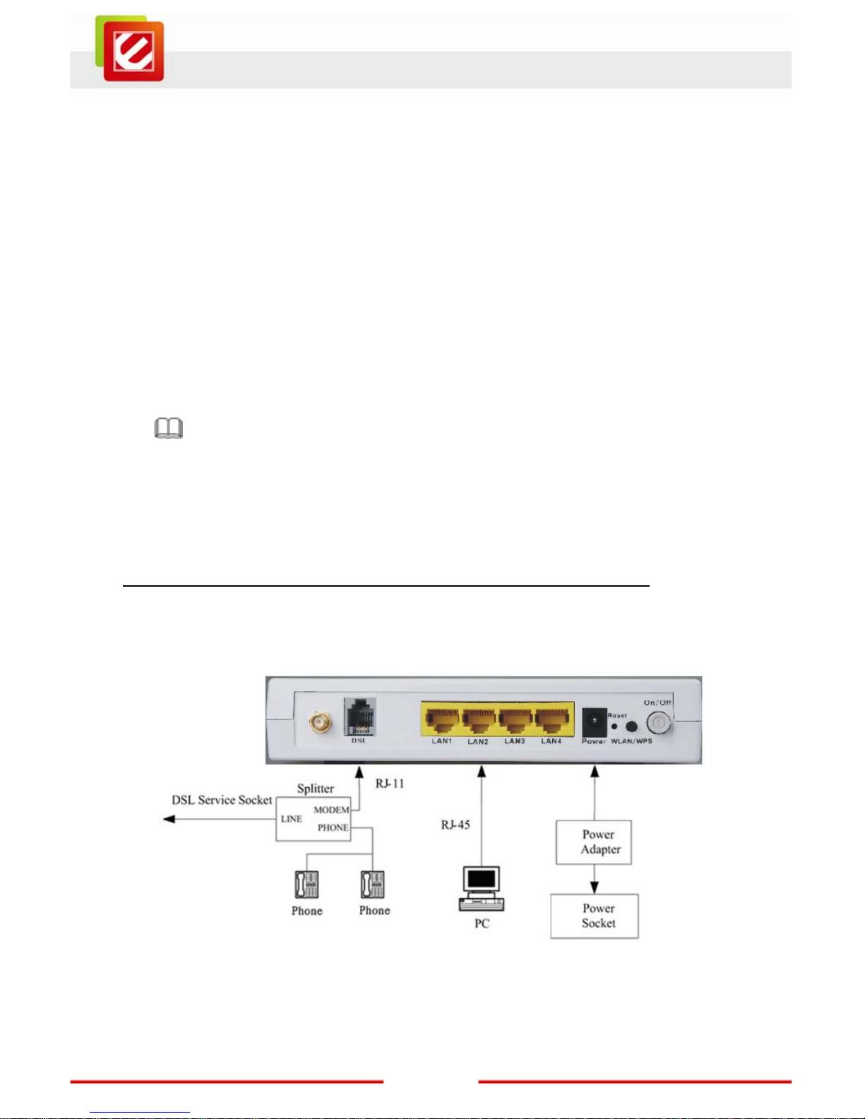
Chapter 2 Hardware Installation
Step 1 Connect the DSL interface of the device to the MODEM interface of the splitter
through a telephone cable. Connect the phone to the PHONE interface of the
splitter through a cable. Connect the incoming line to the LINE interface of the
splitter.
The splitter has three interfaces:
LINE: Connect to a wall phone jack (RJ-11 jack).
MODEM: Connect to the ADSL jack of the device.
PHONE: Connect to a telephone set.
Step 2 Connect the LAN interface of the device to the network interface card (NIC) of the
computer through an Ethernet cable (MDI/MDIX).
Note:
Use twisted-pair cables to conn ect with the hub or switch.
Step 3 Plug one end of the power adapter to the wall outlet and connect the other end to
the Power interface of the device.
2.1 Connection with no telephone set installed before splitter
Figure 1 displays the application diagram for the connection of the router, computer,
splitter and the telephone sets, when no telephone set is placed before the splitter.
Figure 1 Connection diagram (Without connecting telephone set before the splitter)
Page 7
6
www.encore-usa.com
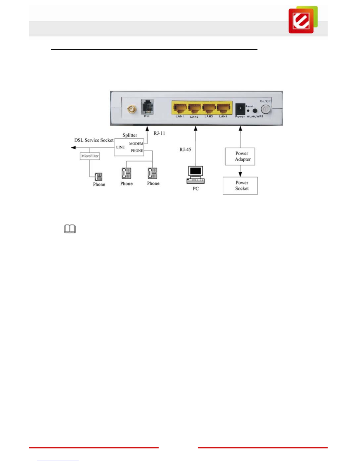
2.2 Connection with telephone set installed before splitter
Figure 2 displays the connection when the splitter is installed close to the router.
Figure 2 Connection diagram (Connecting a telephone set before the splitter)
Note:
When above connection is used, the filter must be installed close to the telephone cable.
See Figure2. Do not use the splitter to replace the filter.
Installing a telephone directly before the splitter may lead to failure of connection between
the device and the central office, or failure of Internet access, or slow connection speed. If
you really need to add a telephone set before the splitter, you must add a micro-filter
before a telephone set. Do not connect several telephones before the splitter or connect
several telephones with the micro-filter.
Page 8
7
www.encore-usa.com
Chapter 3 Setting up the TCP/IP Properties
This chapter describes how to configure the computer to communicate with the router.
Note:
Reboot your Window s sy stem migh t be nec essary after setting your compute r fu nct ion as a
DHCP client. In order to properly activate your choice, click OK to reboot your Windows
system.
3.1 Setting up the TCP/IP Properties
You could follow the instructions and configure the NIC installed on your system as a
DHCP client to get the IP address information automatically from the DSL router device.
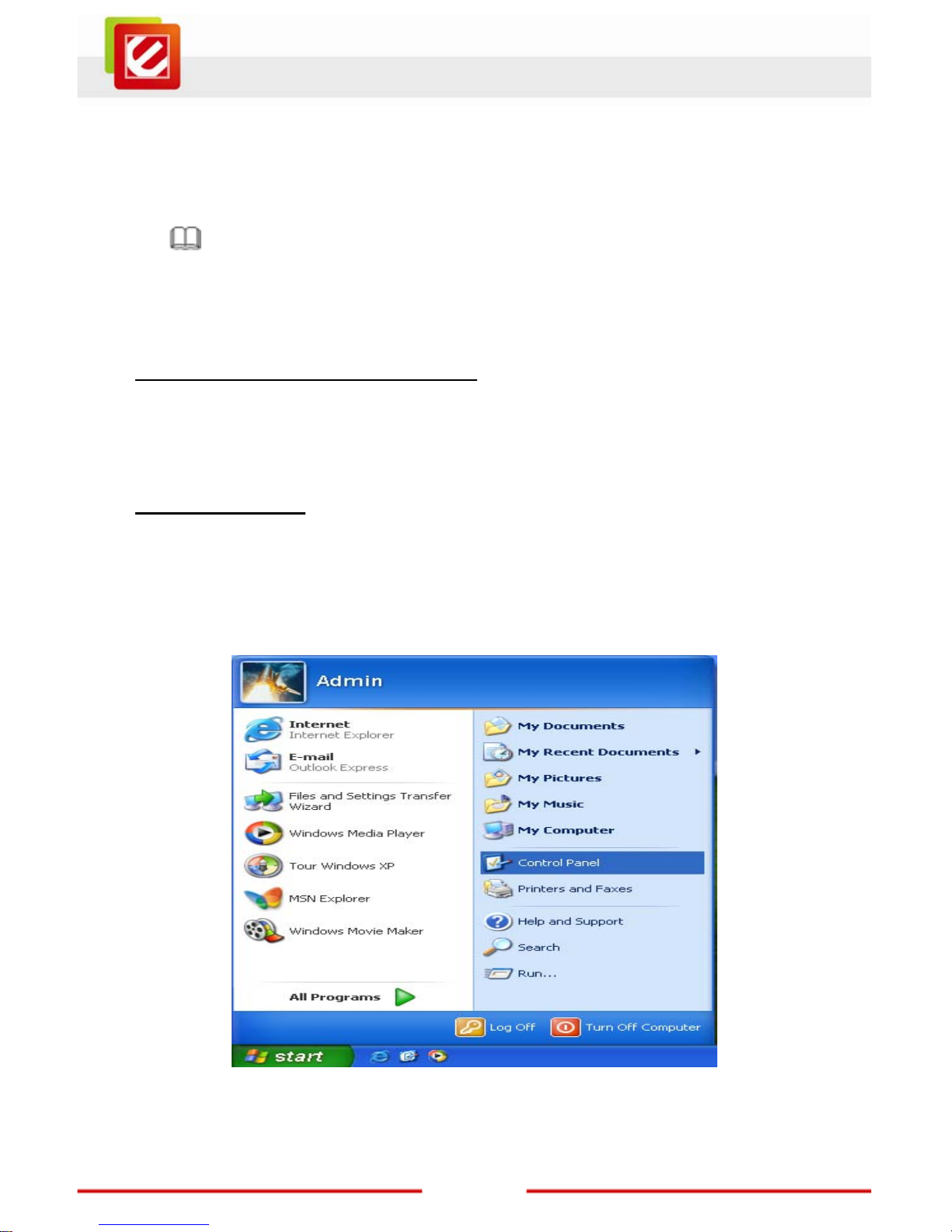
3.1.1 Windows XP
The following describes the operation procedures in Windows XP.
Step 1 Choose Start > Control Panel > Switch to Classic View. The page as shown in
the following figure appears.
Page 9
8
www.encore-usa.com
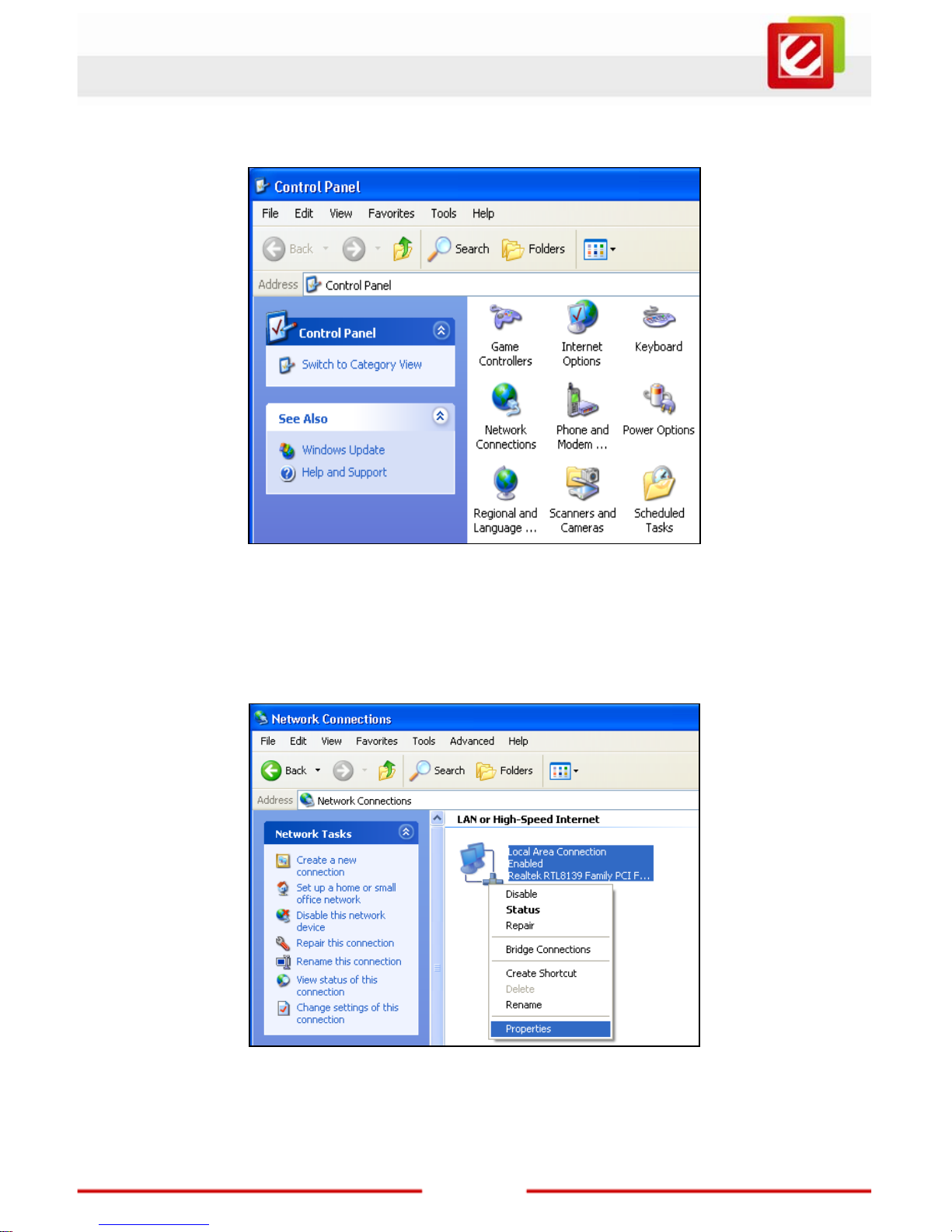
Step 2 Double-click the Network Connections icon.
Step 3 Right-click the Local Area Connection icon, and then select Properties in the
menu.
Page 10

9
www.encore-usa.com
Step 4 In the Local Area Connection Properties window, click the General tab, and
select Internet Protocol (TCP/IP). Then click Properties.
Step 5 Select Obtain an IP address automatically and Obtain DNS server address
automatically.
Page 11

10
www.encore-usa.com
Step 6 After setting, click OK.
3.1.2 Windows Vista/7
The following describes the operation procedures in Windows Vista/7 systems.
Step 1 Choose Start > Control Panel. The page as shown in the following figure appears.
Step 2 Double-click the Network and Sharing Center icon.
Page 12

11
www.encore-usa.com
Step 3 In the left pane, select Manage network connections, the page as shown in the
following figure appears.
Step 4 Right-click the icon of Local Area Connection, and then select Properties in the
menu.
2
1
Page 13

12
www.encore-usa.com
Step 5 In the Local Area Connection Properties window, select Internet Protocol
Version 4 (TCP/IPV4). Then click Properties.
Step 6 Select Obtain an IP address automatically and Obtain DNS server address
automatically.
Step 7 After setting, click OK.
Page 14

13
www.encore-usa.com
3.1.3 Linux System
The following describes the operation procedures in Ubuntu Linux system.
Step 1 Select Network Connections from Preferences on System menu and the page
as shown in the following figure appears. Then, select the Wired tab.
Step 2 Select Auto eth0 item and click the Edit… button to edit the settings.
Page 15

14
www.encore-usa.com
Step 3 On the Edit Auto eht0 window, check the IPv4 Settings tab.
Step 4 On the IPv4 Settings tab, select Automatic (DHCP) from the Method pull-down
menu.
Page 16

15
www.encore-usa.com
Step 5 After setting, click Apply button.
3.1.4 Mac System
The following describes the operation procedures in Mac OS X Version 10.6.3 system.
Step 1 Choose System Preferences from Dock on the system desktop. The page as
shown in the following figure appears.
Step 2 Double-click the Network icon in the Internet & Wireless section, and you will see
the figure below. Click the Ethernet connected from connections list on left side
and select Using DHCP setting in Configure IPv4 option on the right side. And,
you would be able to see the IP Address assignment in the same window
Page 17

16
www.encore-usa.com
Step 3 Click Apply button to finish the settings.
3.2 Checking the TCP/IP Configuration
After you configure the NIC of the computer and reboot the system, you can check the TCP/IP
configuration by using the following utility that is provided by your Windows system.
3.2.1 Windows XP/Vista/7
Step 1 Choose Start > Run.
Step 2 In the Open field, enter cmd, and then click OK.
Step 3 In the prompt window, enter ipconfig /all, and then press Enter. The page as
shown in the following figure appears. All the Ethernet adapter information is
displayed. You can check the configuration of the computer.
Page 18

17
www.encore-usa.com
IP Address: 192.168.1.x
Subnet Mask: 255.255.255.0
Default Gateway: 192.168.1.1
Step 4 Enter Exit, and press Enter. Then the prompt window logouts.
3.2.2 Linux System
Step 1 Access the command line Terminal window from the Accessories sub-menu in the
Applications menu.
Step 2 Use “ifconfig” command to check the IP address assignment in the command line.
Page 19

18
www.encore-usa.com
Chapter 4 Access the Web Configuration
4.1 How to Access the Router
The following is the detailed description of accessing the router for the first time.
Step 1 Open the Internet Explorer (IE) or other browser software and enter
http://192.168.1.1
in the URL address field.
Step 2 In the Login page that is displayed, enter the user name and password.
The user name and password of the super user are admin and admin respectively.
If you log in as a super user, the page as shown in the following figure appears. You can check,
configure and modify all the settings.
If there is no operation in the Web configuration page within five minutes, the router
automatically logouts. You need to log in again.
Note:
In the Web configuration page, you can click Apply Changes to save the settings
temporarily. If you want to save the settings in this page permanently, click Save of
Attention that appears at the bottom of the Web page after the configuration.
Page 20

19
www.encore-usa.com
4.2 Wizard
The Wizard page guides fast and accurate configuration of the Internet connection and other
important parameters. The following sections describe these various configuration
parameters. Whether you configure these parameters or use the default ones, click Next to
enable your Internet connection.
When subscribing to a broadband service, you should be aware of the method by which you
are connected to the Internet. Your physical WAN device can be either PPP, ADSL, or both.
The technical information about the properties of your Internet connection is provided by your
Internet service provider (ISP). For example, your ISP should inform you whether you are
connected to the Internet using a static or dynamic IP address, and the protocol that you use
to communicate on the Internet.
In the navigation bar, click Wizard. The page as shown in the following figure appears.
The following table describes the parameters in this page:
Field Description
User Name Select the user name for accessing the router.
New Password
Enter the password to which you want to change the old
password. The password can not contain space key, %,
“, ? or &.
Confirmed Password Enter the new password again.
You are recommended to change the password after login for the first time. Enter the new
password twice and click Next. The page as shown in the following figure appears. In this
page, you can configure the system time and Network Time Protocol (NTP) server.
Page 21

20
www.encore-usa.com
The following table describes the parameters in this page:
Field
Description
State
Disable or enable NTP. You need to enable it if you want to
configure the parameters in this page.
Server IP Enter the IP address of the specified time server manually.
Interval
Specify the interval that the router synchronizes the time with the
server.
Time Zone Select the time zone in which area you are from the drop-down list.
GMT time It displays the Greenwich Mean Time (GMT).
After setting, click Next. The page as shown in the following figure appears.
The procedure for configuring the ADSL settings of the router is as follows:
Step 1 Select the country where you are from the drop-down list.
Page 22

21
www.encore-usa.com
Step 2 Select the corresponding ISP from the drop-down list.
After the selection, the protocol, connection type, VPI, VCI are displayed.
Step 3 Enter the correction information for dial-up.
There are six protocols available: PPPoE, PPPoA, 1483 MER: DHCP, 1483 MER: Static IP,
1483 Bridged, and 1483 Routed.
For example, please select Singapore and Infoserve Dial-up connection ADSL service
from the corresponding drop-down lists. The page as shown in the following figure appears.
PPPoE
In this example, select PPPoE as the protocol.
The following table describes the parameters in this page:
Field
Description
Protocol
There are six protocols available. In this example, PPPoE is the
protocol for dial-up.
Connection
Type
There are two connection types available: VC-Mux and LLC. In
this example, LLC is the connection type.
VPI
Virtual path identifier (VPI) is the virtual path between two points
in an ATM network. Its valid value is in the range of 0 to 255. In
this example, VPI is set to 0.
VCI
Virtual channel identifier (VCI) is the virtual channel between
two points in an ATM network. Its valid value is in the range of
32 to 65535 (0 to 31 is reserved for local management of ATM
traffic). In this example, VCI is set to 100.
Page 23

22
www.encore-usa.com
Field
Description
User Name
Enter the user name for PPPoE dial-up, which is provided by
your ISP.
Password
Enter the password for PPPoE dial-up, which is provided by
your ISP.
Confirmed
Password
Enter the password again.
PPPoA
Select PPPoA as the protocol, the page as shown in the following figure appears.
For the parameters in this page, refer to the parameter description of PPPoE protocol.
Page 24

23
www.encore-usa.com
1483 MER: DHCP
Select 1483 MER: DHCP as the protocol, the page as shown in the following page appears.
After entering correct VPI and VCI, DHCP automatically assigns the WAN IP address,
gateway and DNS information to this device.
1483 MER: Static IP
Select 1483 MER: St atic IP as the protocol, the page as show n in the following page appears.
Page 25

24
www.encore-usa.com
The following table describes the parameters in this page:
Field
Description
Protocol
There are six protocols available. In this example, 1483 MER:
Static IP is the protocol for dial-up.
Connection
Type
There are two connection types available: VC-Mux and LLC.
In this example, LLC is the connection type.
VPI
Virtual path identifier (VPI) is the virtual path between two
points in an ATM network. Its valid value is in the range of 0 to
255. In this example, VPI is set to 0.
VCI
Virtual channel identifier (VCI) is the virtual channel between
two points in an ATM network. Its valid value is in the range of
32 to 65535 (0 to 31 is reserved for local management of ATM
traffic). In this example, VCI is set to 100.
WAN IP Address
Enter the IP address for WAN connection, which is provided
by your ISP.
Subnet Mask
Enter the subnet mask of the WAN IP address, which is
provided by your ISP.
Default Gateway Enter the default gateway, which is provided by your ISP.
Primary DNS
Server
Enter the DNS server, which is provided by your ISP.
1483 Bridged
Select 1483 Bridged as the connection type, the page as shown in the following figure
appears.
Page 26

25
www.encore-usa.com
1483 Routed
Select 1483 Routed as the connection type, the page as shown in the following figure
appears.
In this page, you need to enter the IP address of WAN connection, subnet mask, default
gateway, and DNS server which are provided by your ISP.
For parameters in this page, refer to the parameter description of 1483 MER: Static IP.
After setting, click Next, the page as shown in the following page appears.
The following table describes the parameters in this page:
Field
Description
Page 27

26
www.encore-usa.com
Field
Description
WLAN
Interface
Enable or disable WLAN.
You need to enable WAN interface only if you want to use
WLAN and configure the parameters in this page.
Band
Select the working mode of the router. You can select 802.11b,
802.11g, or Mixed (802.11b/11g).
SSID
The service set identification (SSID) is a unique name to identify
the router in the wireless LAN. Wireless stations associating to
the router must have the same SSID. Enter a descriptive name
that is used when the wireless client connecting to the router . By
default, the SSID is ENDSL-4R5G.
Encryption
Configure the wireless encryption mode. You can choose None,
WEP, WPA (TKIP), WPA (AES), WPA2 (AES), WPA2 (TKIP),
or WPA2 Mixed.
Wired equivalent privacy (WEP) encrypts data frames
before transmitting over the wireless network.
Wi-Fi protected access (WPA) is a subset of the
IEEE802.11i security specification draft.
WPA 2 Mixed is the collection of WPA and WPA2 encryption
modes. The wireless client establishes the connection
between the router through WPA or WPA2.
Key differences between WPA and WEP are user authentication
and improved data encryption.
Set the encryption to WEP, the page as shown in the following figure appears.
The following describes the parameters of WEP encryption:
Field Description
Key Length Select the WEP key length. You can select 64-bit or 128-bit.
Key Format
If the key length is set to 64-bit, you can select ASCII (5
characters) or Hex (10 characters).
If the key length is set to 128-bit, you can select ASCII
(13 characters) or Hex (26 characters).
Key
The encryption key is used to encrypt the data. Both the
router and wireless stations must use the same encryption
key for data transmission.
If you select 64-bit and ASCII (5 characters), enter any
Page 28

27
www.encore-usa.com
Field Description
5 ASCII characters.
If you select 64-bit and Hex (10 characters), enter any
10 hexadecimal characters.
If you select 128-bit and ASCII (13 characters), enter
any 13 ASCII characters.
If you select 128-bit and Hex (26 characters), enter
any 26 hexadecimal characters.
Set the encryption to WPA (TKIP), the page as shown in the following figure appears.
The following table describes the parameters of WPA (TKIP) encryption:
Field Description
Enterprise (RADIUS)
If you select it, you need to enter the port, IP address, and
password of the Radius server. You need to enter the user
name and password provided by the Radius server when
the wireless client connects the router.
Personal
(Pre-Shared Key)
If you select it, you need to enter the pre-shared key in the
Pre-Shared Key field.
For the parameters of WPA (AES), WPA2 (TKIP), WPA2 (AES), and WPA2 Mixed refer to the
parameter description of WPA (TKIP).
After finishing the configuration, click Next. The page as shown in the following figure
appears.
Page 29

28
www.encore-usa.com
Click Back to modify the settings.
Click Finish to take the settings into effect temporarily.
Click Reset to cancel the settings.
After the configuration, you may open your browser software and check your favorite web
sites.
4.3 Technical Support
For more details of product information or configuration, please check the user manual in the
CD-ROM came with the product.
For technical support related issues, please check the Support section on our web site
http://www.encore-usa.com
.
Page 30

29
www.encore-usa.com
Product specifications, size, and shape ar e subject to c hange wi thout notice, and actual product appe arance m ay dif fer from that depic ted herein.
All trademarks and brand names are the properties of their respective holders.
* Local tech-support numbers are provided in selectively countries. Service may change without prior notice.
Please visit www.encore-usa.com for more details.
 Loading...