

Page 1

© 2010 Encore Electronics, Inc. All rights reserved.COVER
© 2010 Encore Electronics, Inc.
Product specifications, size, and shape are subj ect to change without notice, and actual product appearance m ay diffe r f rom that depicted herein.
All trademarks and brand names are the properties of their respective holders.
Page 2

www.encore-usa.com
TABLE OF CONTENTS
1. INTRODUCTION ............................................................................................... 4
1.1 FEATURES & BENEFITS ............................................................................ 5
1.2 PACKAGE CONTENTS ............................................................................... 6
1.3 SAFETY GUIDELINES ............................................................................... 6
1.4 WIRELESS SOHO ROUTER DESCRIPTION ................................................ 7
1.5 SYSTEM REQUIREMENTS ......................................................................... 9
1.6 APPLICATIONS ......................................................................................... 9
1.7 NETWORK CONFIGURATION................................................................... 11
a) Ad-hoc (peer-to-peer) Mode ..................................................................... 11
b) Infrastructure Mode .................................................................................. 12
2. INSTALLATION ............................................................................................... 13
2.1 HARDWARE CONNECTION...................................................................... 13
2.2 LOGIN TO THE WEB-BASED CONFIGURATION UTILITY ............................ 14
3. WEB-BASED CONFIGURATION .................................................................. 18
3.1 BASIC .................................................................................................... 19
3.1.1 Internet Settings .............................................................................. 19
Internet Connec tion Type............................................................................ 20
DHCP Connection (Dynamic IP Address) .................................................. 21
PPPoE (Point-to-Point Protocol o v er Ethernet) .......................................... 22
PPTP (Point-to-Point Tunneling Protocol).................................................. 23
Static IP Address Configuration .................................................................. 24
3.1.2 Other Internet Settings .................................................................... 25
DNS Settings .............................................................................................. 25
MTU Settings ............................................................................................. 25
WAN Ping................................................................................................... 26
Multicast Streams ....................................................................................... 26
1
Page 3

www.encore-usa.com
MAC Cloning ............................................................................................. 26
3.1.3 Wizard Wireless ............................................................................... 27
Automatic Network Setu p .......................................................................... 28
Manual Network Setup ............................................................................... 28
3.1.4 Network Settings ............................................................................. 31
Bridge Mode ............................................................................................. 31
Router Mode ............................................................................................. 32
RIP (Routing Information Protocol) ........................................................... 34
DHCP Server Settings ................................................................................ 36
Add/Edit DHCP Reservation ...................................................................... 39
3.1.5 Wirele ss S e ttings ............................................................................. 41
WEP (Wired Equivalent Privacy) ............................................................... 43
WPA Personal (Wi-Fi Protected Access) .................................................... 45
WPA Enterprise (Wi-Fi Protected Access & 802.1x) .................................. 47
3.2 ADVANC ED ............................................................................................ 49
3.2.1 Advanced Wireless .......................................................................... 49
3.2.2 Virtual Server .................................................................................. 52
3.2.3 Special Applications ....................................................................... 53
3.2.4 Port Forwarding ............................................................................. 54
3.2.5 StreamEngine .................................................................................. 55
3.2.6 Routing............................................................................................ 59
3.2.7 Access Control ................................................................................ 60
3.2.8 Web F ilte r ....................................................................................... 63
3.2.9 MAC Address Filter ........................................................................ 64
3.2.10 Firewall ........................................................................................... 65
3.2.11 Inbound Filter ................................................................................. 71
3.2.12 WISH ............................................................................................... 72
3.2.13 Wi-Fi Protected Setup ..................................................................... 75
2
Page 4

www.encore-usa.com
3.2.14 Advanced Network .......................................................................... 77
3.3 TOOLS ................................................................................................... 79
3.3.1 Time Zone Setting ........................................................................... 79
3.3.2 System ............................................................................................. 81
Save To Local Hard Drive ....................................................................... 82
Load From Local Hard Drive .................................................................. 83
Restore To Factory Default ..................................................................... 84
Reboot the device .................................................................................... 85
3.3.3 Firmware Upgrade ......................................................................... 86
3.3.4 System Logs .................................................................................... 87
3.3.5 Dynamic DNS ................................................................................. 88
3.3.6 System Check .................................................................................. 89
3.3.7 Schedules ........................................................................................ 90
3.4 STATUS .................................................................................................. 91
3.4.1 Wirele ss Status ................................................................................ 91
3.4.2 Logs Status ...................................................................................... 93
3.4.3 Statistics .......................................................................................... 94
3.4.4 WISH Session Status ....................................................................... 94
3.4.5 Routing............................................................................................ 96
3.4.6 Internet Session Status .................................................................... 96
3.4.7 Firewall ........................................................................................... 98
APPENDIX A – GLOSSARY ............................................................................... 99
Product specifications, size, and shape are subject to change without notice, and actual
product appearance may differ from that depicted herein.
All trademarks and brand names are the properties of their respective holders.
© 2010 Encore Elect ronics, Inc. All rights reserved.
3
Page 5

www.encore-usa.com
1. Introduction
The EN2HWI-N3 wir el ess N 300 gigabi t gam i ng r outer is an 802.11n compliant device t hat
delivers up to 6x faster speeds than 802.11g while staying backward compatible with
802.11g and 802.11b devices.
It is not only a Wir eless Access Point, whi ch lets you connect to the network without wires.
There's also a built-in 4-port full-duplex 10/100/1000 Gigabit Switch to connect your
wired-Ethernet devices together. The Router function ties it all together and lets your whole
network shares a high-speed cable or DSL Internet c onnection.
The Access Point built into the Router uses ad vanced MIMO (Multi-Input, Mul ti-Output)
technology to tr ansmit multiple steams of data i n a single wireless channel. The robust
signal travels fart her, maintaining wir el ess c onnec t ions up t o 3 times f art her than standar d
802.11g, eliminates dead spots and extends network range.
To protect the data and privacy, the Router can encode all wireles s transmissions with
64/128-bit encrypt ion. It can serve as your n etwork's DHCP Server, has a powerful SPI
firewall to protect your PCs against intruders and most known Internet attacks, and
supports VPN pass-through. The router also provide easy configuration with the web
browser-based configuration utility.
The incredible speed and QoS function of EN2HWI-N3 are ideal for media-centric
applications like streaming video, gaming, and VoIP telephony. It is designed to run
multiple media-intense data streams through the network at the same time, with no
degradation in perf ormance.
This chapter describes the features & benefits, package contents, applications, and
network configuration.
4
Page 6

www.encore-usa.com
(Auto-Crossover)
Filter, ICMP Blocking, SPI
1.1 Features & Benefits
Features Benefits
High Speed Data Rate Up to
300Mbps
IEEE 802.11n Compliant and
backward compatibl e w ith
802.11b/g
Four built-in
10/100/1000Mbps Gigabit
Switch Ports
QoS: StreamEngine, WISH
and WMM
Supports DNS/ DDNS Let users assi gn a fixed host and domain name t o
Supports NAT (Network
Address Translation)/NAPT
Hide SSID Avoid unallowable users sharing bandwi dth,
Firewall suppor ts Virtual
Server Mapping, DM Z, IP
Support 802.1x
authenticator, 802.11i
(WPA/WPA2, AES), VPN
pass-thru mechanisms
WDS (W ireless Distribution
System)
Universal Plug and Play
(UPnP™)
Filter Scheduli ng The filter can be scheduled by days, hours or
Real time alert Record suspic ious actives in the Logs Status
Capable of handling heavy data payloads such as
MPEG video streaming
Fully interoperable with IEEE 802.11b/g/n devices
Scalability, able to extend your n etwork
Help improve the netw ork performance by
prioritizing applications.
a dynamic Internet IP address.
Share single Inter net account and provides a type
of firewall by hiding internal IP addresses for
keeping hacker out
increases efficiency of the network
Avoid the attacks of Hackers or Viruses from
Internet
Provide mutual authentication (cl ient and dynamic
encryption keys to enhance security)
Extend your wireless network by operat ing as a
wireless repeater
Work with most Internet gami ng and instant
messaging applications for automatic Internet
access
minutes for easy m anagement
5
Page 7

www.encore-usa.com
Web configuration Help administr ators to remotely configure or
manage the router via Telnet/Web-browser
1.2 Package Contents
Open the package carefully, and make sure that none of the items listed below are missing.
Do not discard the packing mater ials, in case of return; the unit must be shipped in its
original package.
EN2HWI-N3 wireless N300 gigabit gaming router x 1
DC Power Adapter x 1
3dBi 2.4GHz Dipole Antennas x 2
US to EU converter x 1
Setup CD with User Manual x 1
Quick Installation Guide x 1
1.3 Safety Guidelines
In order to reduce t he risk of fire, electr ic shock and injur y, please adhere to the foll owing
safety guidelines .
Carefully follow the i nst ruct ions in t he User Manual and als o foll ow all i nstr uction l abels
on this device.
Except for the power adapter supplied, this device should not be connected to any other
adapters.
Do not spill liquid of any kind on this devic e.
Do not place the device on an unstable stand or table.
Do not expose this unit to direct sunlight.
Do not place any hot devices close to the device, as they may degrade or cause
damage to the unit.
Do not place any heavy ob jects on top of the devic e.
Do not use liquid cleaner s or aerosol cleaners. Use a soft dry c loth for cleaning.
6
Page 8
www.encore-usa.com
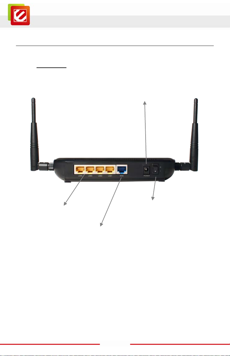
1.4 Wireless SOHO Router Description
Rear Panel
Power Jack
LAN Ports
Power S w i tch
WAN / Internet Port
7
Page 9
www.encore-usa.com
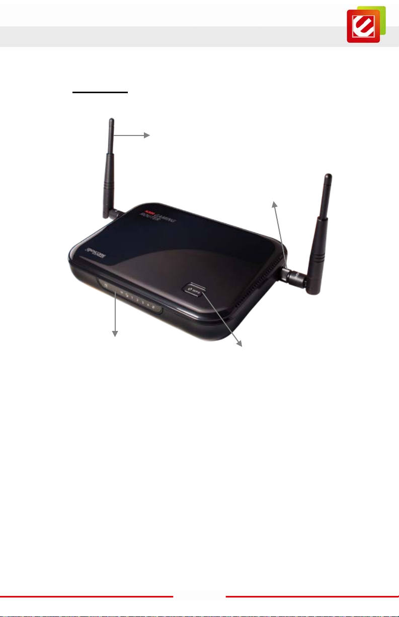
Antenna
Front Panel
Antenna
Connector
LED panel
WPS button
8
Page 10
www.encore-usa.com
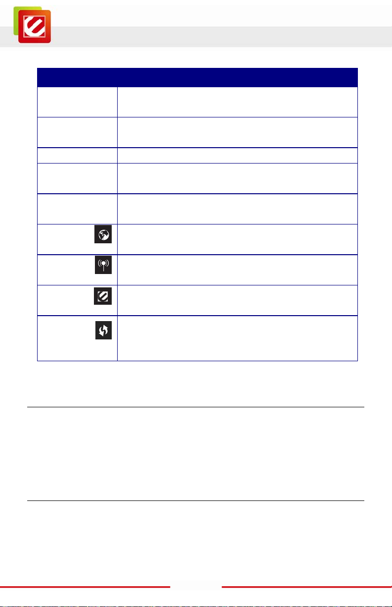
Parts Description
LAN Ports (1 – 4) Use an Ethernet cable to connect each por t to a computer on
your Local Area Network (LAN) .
WAN Port Use an Ethernet cable to connect this port to your WAN
router.
Power Switch Turn on or off the device
Antenna
Connector
LAN LED This LED will l ight up once an Ethernet cable is connected to
WAN LED This LED will l ight up once an Ethernet cable is connected to
WLAN LED This LED will l ight up once the RF (wireless LAN) feature is
Power LED This LED will light up once the power cable is connected to
WPS button 1- 5 seconds: Activates WPS
1.5 System Requirements
Interface for the antennas.
one of the LAN ports.
WAN (Internet) port.
enabled
the DC connector.
6-10 seconds: System Reboot
11+ seconds: Reset to factory default
The following are the minimum system requirements in order to configure the device.
A computer with an Ethernet interface
Operating system that supports HTTP web-browser
1.6 Applications
The wireless LAN products are easy to install and highly efficient. The following list
describes some of the many applic ations made poss ible through t he power and fle xibility
of wireless LANs :
9
Page 11

www.encore-usa.com
a) Difficult-to-wire environments
There are many si tuations where wires c annot be laid easily. Historic buil dings, older
buildings, open areas and across busy streets make the installation of LANs either
impossible or very expensive.
b) Temporary workgroups
Consider situations in parks, athletic arenas, exhibition centers, disaster-recovery,
temporary offices and construction sites where one wants a temporary WLAN
established and removed.
c) The ability to access real-time information
Doctors/nurs es, poi nt-of-s ale employe es, and ware house work ers can acc ess real -time
information whil e dealing with patients, serving custom ers and processing information.
d) Frequently changed en vironments
Show rooms, meeti ng rooms, retail stores, and manuf acturing sites where fr equently
rearrange the workplace.
e) Small Office and Home Of fice (SOHO) networks
SOHO users need a cos t-effective, easy and quic k installation of a small network.
f) Wireless extensions to Ethernet networks
Network managers in dynamic environments can minimize the overhead caused by
moves, extensions to networks, and other changes with wir eless LANs.
g) Wired LAN backup
Network managers implement wireless LANs to provide backup for mission-critical
applications r unning on wired networ ks.
h) Training/Educational facilities
Training sites at corporati ons and students at universities use wireles s connectivity to
ease access to information, information exchanges, and learning.
10
Page 12
www.encore-usa.com
1.7 Network Configuration
To bett er understand how the wireles s LAN products work together to creat e a wireless
network, it might be helpful to d epict a f ew of the poss ible wir eless LAN PC c ard network
configurations . The wireless LAN products can be configured as:
a) Ad-hoc (peer-to-peer) for departmental or SOHO LANs.
b) Infrastructure for enterprise LANs .
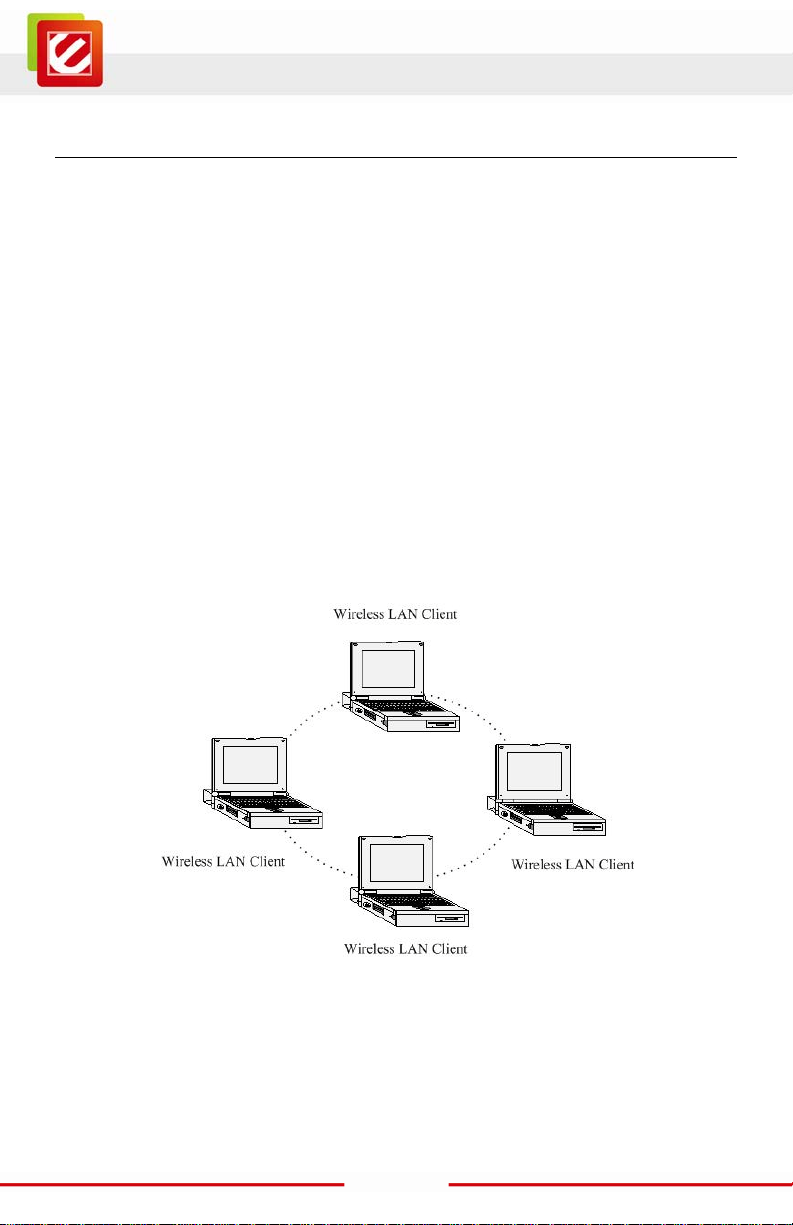
a) Ad-hoc (peer-to-peer) Mode
This is the simples t netw ork conf igur ati on wi th s ever al c omput er s equi pped wi th t he PC
Cards that form a wirel ess net work whenever they ar e wit hin ra nge of one anot her. In
ad-hoc mode, each client is peer-to-peer, would only have access to the resources of the
other client and does not require an access point. This is the easiest and least expensive
way for the SOHO to set up a wir eless networ k. The im age below depic ts a networ k in
ad-hoc mode.
11
Page 13
www.encore-usa.com
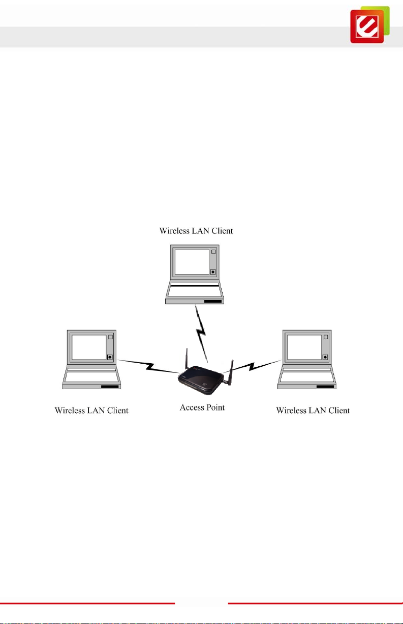
b) Infrastructure Mode
The infrastructure mode requires the use of an access point (AP). In this mode, all
wireless communication between two computers has to be via the AP. It doesn’t matter if
the AP is stand-alone or wired to an Ethernet network. If used in stand-alone, the AP can
extend the range of independent wireless LANs by acting as a repeater, which effectively
doubles the distance between wireless stations. The image belo w depicts a network in
infrastruct ure mode.
12
Page 14
www.encore-usa.com
EN2HWI-N3 Router
Computers
Wall Power Outlet
DC Power Adapter
2. INSTALLATION
2.1 Hardware Connection
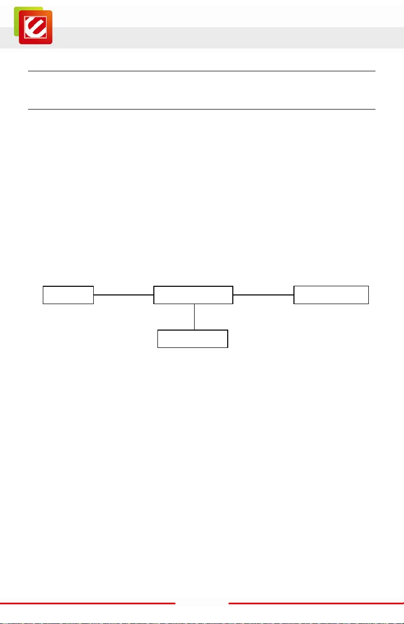
1. Place the EN2HWI-N3 router in an appropriate locati on after conducting a site survey.
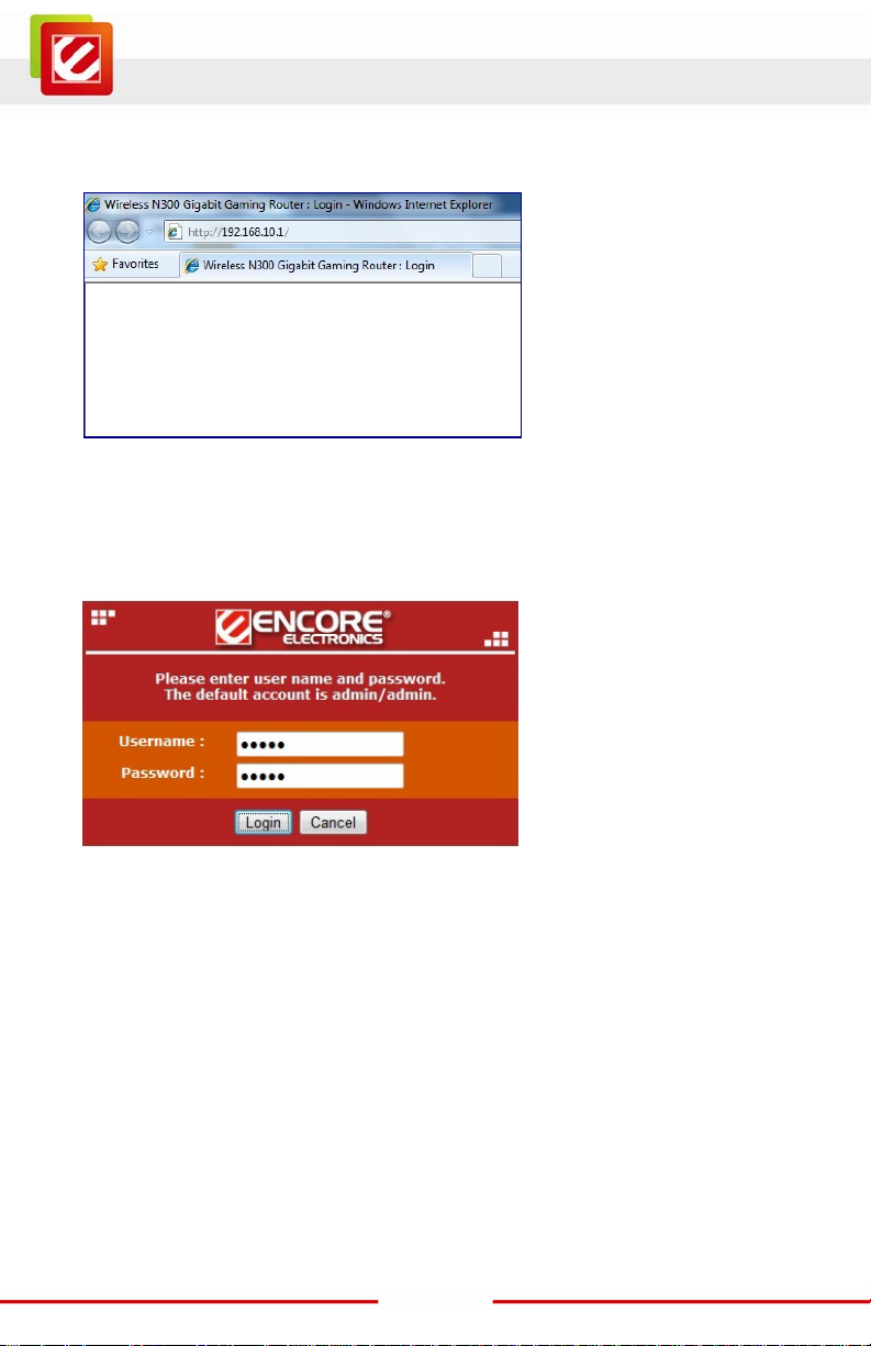
2. LAN connection: Connect Ethernet cable between your PC/ N otebook LAN port & one of
the 4 available LAN ports on EN2HWI-N3.
3. WAN connection: Connect Ethernet cable between WAN port of your DSL/CABLE
modem & WAN port of EN2HWI-N3. Make sure your DSL/Cable modem is already setup
and working well. Contact your ISP (Internet Service Provider) if you have any questions.
4. Connect the supplied power-ad apter to the power port and then plug it to a wall power
outlet.
This diagram depicts the hardware conf iguration:
LAN
WAN
DSL / Cable Modem
13
Page 15
www.encore-usa.com
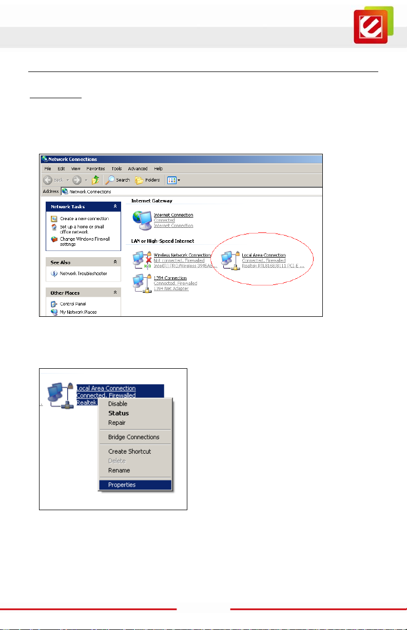
2.2 Login to the web-based configuration utility
Windows XP
1. Assuming your PC or Laptop is already equipped with a N etwork Interfac e C ard and
properly working. Click on START sel ect “Control Panel” From the Cont rol Panel
Window select “ N etwork Connections”
2. Right-click (Use the right button of your mouse) the “Local Area Connection” icon then
select and click “Properties”
14
Page 16
www.encore-usa.com
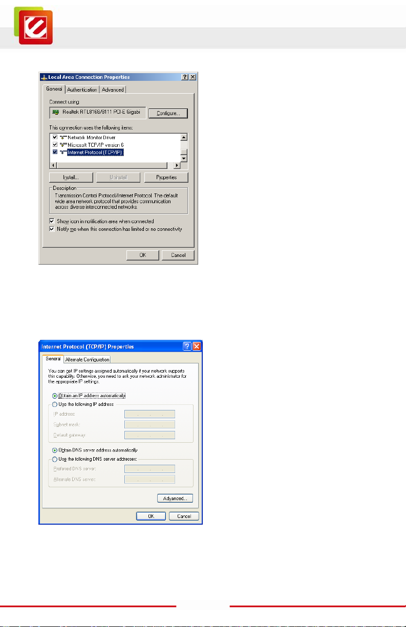
3. Click to Highlight the “Int ernet Protocol (TCP/IP)” t hen click “Properties” but ton
4. Select the “General” tab.
The EN2HWI-N3 support s DHCP Client function, select bot h “Obtain an IP address
automatically” and “Obtain DNS server address automatically”
15
Page 17
www.encore-usa.com
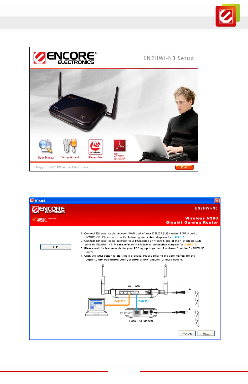
5. Insert the Setup CD into the CD-ROM drive; the setup screen will automati cally appear.
Click the “Setup Wizard” butt on, and then follow the on-screen instructions.
The final Setup Page as below:
Click the “OK” butt on to open your web brows er with Login Page.
16
Page 18
www.encore-usa.com
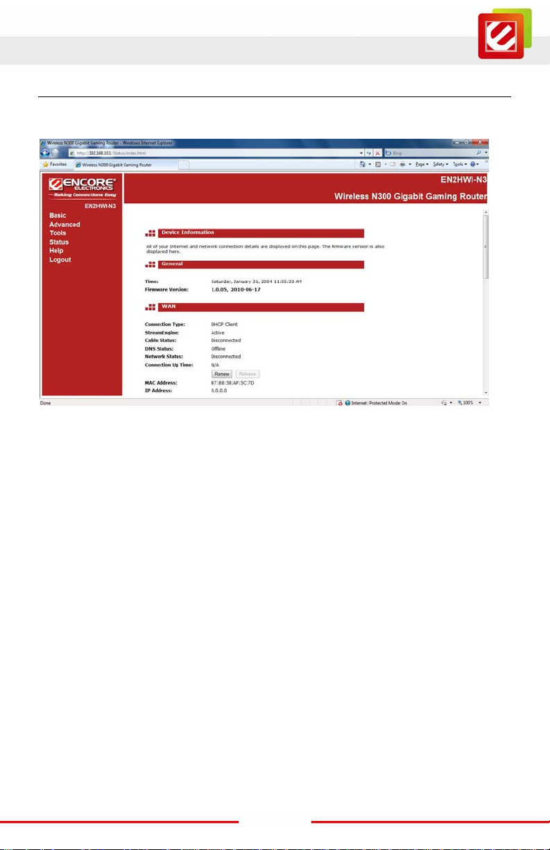
6. For manually Login to the web-based configurat ion utilit y with out the Setu p CD, open
your web browser, and then type-in http://192.168.10.1 exactly in address f ield.
7. Input the Username and Password, and the click [Login] button to navigate i nto the
EN2HWI-N3 configuration home page. The factory default username is admin and
password is also admin.
17
Page 19
www.encore-usa.com
3. Web-based Configuration
After login, you wi ll see the configurat ion home page of the EN2HWI-N3 as foll ow s.
The navigation tree menu on left is divided following sections:
1. Basic: This menu includes the wi reles s wizar d, networ k set tings , wirel ess sett ings , and
WAN settings.
2. Advanced: This menu includes virtual server, special applications, port forwarding,
routing, access control, web filter, MAC address filter, firewall, WPS, etc.
3. Tools: This menu includes t ime, firmware, sys tem log, DDNS, schedules, etc.
4. Status: This menu displays the wireless status, logs, statistics, routing, and internet
sessions, etc.
5. Help: Displays the help for configuration.
6. Logout: Logout the Web-based Configuration.
18
Page 20

www.encore-usa.com
3.1 Basic
Click on the Basic link on the navigation drop-down menu.
3.1.1 Internet Settings
This chapter desc ribes how to use the wizard t o configure the W AN, LAN, and wireless
settings. Pleas e refer to Chapter 3.2 in or der to configure t he more advanced f eatures of
the EN2WI-N3.
IMPORTANT NOTICE
Internet Setti ngs Page contains various settings related to WAN / Internet service.
Usually, you only need to configure Internet Connection Type section to connect to
the Internet. Unl ess your ISP Provider specified otherwise, please keep t he default
settings if you are unsure of the configuration. Please consult your local ISP Provider
for your Internet C onnection Type and account information.
Click on the Internet Settings to begin the pr ocess.
19
Page 21
www.encore-usa.com
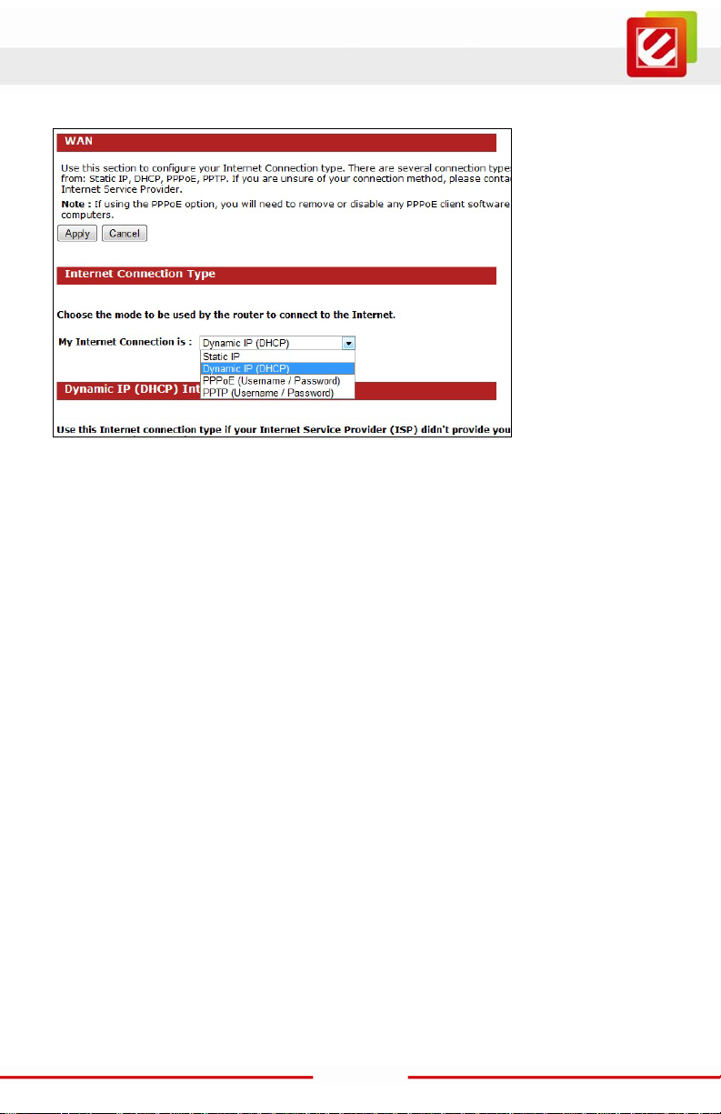
Internet Connection Type
Select your Internet service WAN type
The EN2HWI-N3 supports several types of Internet / WAN connections:
o DHCP Connect ion (Dynamic IP addr ess) – Choose this connection type if your ISP
provides you the IP address. Most cabl e m odem s use this type of connection.
o PPPoE (Point-to-Point Protocol over Ethernet) – Choose this connection t ype if
your internet connection requires a user name and password. Most DSL modems use
this type of connection.
o PPTP (Point-to-Point Tunneling Protocol) – Choose this connection type if your ISP
requires to use PPT P. Your ISP should provide you with a user name and password.
o Stat ic IP address – Choose this connection type if your ISP has assigned a fixed
public IP address for you to use.
Page content will change in accords to the Internet Connect ion option. Please consul t
your local ISP for the appropri ate choic e. The followi ng secti ons explain the s upported
Internet type.
20
Page 22

www.encore-usa.com
DHCP Connection (Dynamic IP Address)
The WAN interfac e can be configured as a DHCP Client in which the I SP provides the IP
address to the EN2HWI-N3. This is also known as Dynamic IP.
Host Name: this is optional if you need to specify the host name for this router.
Use Unicasting: Thi s option is normally turned of f, and shoul d remain off as long as the
WAN-side D HCP server correctly provides an I P address to the router. Howev er, if the
router cannot obt ain an IP addres s from the DHCP ser ver, the DHCP server may be one
that works bett er with unicas t responses. I n this case, t urn the unicast ing option on, and
observe whether the r outer can obtain an IP address. In t his mode, the router accepts
unicast responses from the DHCP server instead of broadcas t responses.
21
Page 23

www.encore-usa.com
PPPoE (Point-to-Point Protocol over Ethernet)
The WAN interface can be configured as PPPoE. This type of connection is usually used for
a DSL service and requires a username and password to connect.
Address Mo de: PPPoE can be used wi th a dynam ic or s tatic IP addr ess. I f you selec t
the Dynamic IP radio button, then the IIP address in the next field is not required.
However, if you sel ec t the St atic IP r adio but ton, t hen the I P ad dres s i n the next f iel d is
required.
IP Address: Enter the IP address if the Static IP is selec ted.
User Name: Enter the username whi ch is provided by your ISP.
Password: Enter the password which is provided by your ISP.
Verify Password: Enter the password again for verifi cation.
Service Name: This is optional. Enter the ISP name.
Reconnect Mode:
o Keep Connecti on: will stay connected to the Internet.
o Automatic Connect: automatical ly connects to the Internet when an application needs
it, and drops the connection after the designated idle time per iod.
o Manual Connect: manually connect and disconnect to the internet by the user.
22
Page 24

www.encore-usa.com
Maximum Idle Time: This is for the Internet connection is maintained during inactivity. If
the application is inactive for certain time designated here the internet connection will be
automatically dropped.
PPTP (Point-to-Point Tunneling Protocol)
PPTP uses a virtual pr ivate network to connect to your ISP. This method of connect ion
requires you to enter a username and pas sword (pr ovided by yo ur ISP) t o gain access to
the Internet. The supported authenti cation protocols are PAP and CHAP.
Address Mo de: PPTP can be used with a dynamic or static IP address. If you select the
Dynamic IP radio button, then the IIP address in the next field is not required. However,
if you select the St atic IP radio button, then the IP address in the next field is required.
PPTP IP Address: Enter the IP address
PPTP Subnet Mask: Enter the subnet Mask for the IP address.
PPTP Gateway IP Address: Enter the IP address of the PPT P gateway.
PPTP Server IP Address: Enter the PPTP Ser ver’ s IP addr es s if it is dif f erent from the
default gateway.
Username: E nter the user name whic h is provided by your ISP .
Password: Enter the passwor d which is provided by your ISP.
Verify Password: Enter the password again for verifi cation
23
Page 25

www.encore-usa.com
Reconnect Mode:
o Keep Connecti on: will stay connected to the Internet.
o Automatic Connect: automatical ly connects to the Internet when an application needs
it, and drops the connection after the designated idle time peri od.
o Manual Connect: manually connect and disconnect to the internet by the user.
Maximum Idle Time: This is for the Internet connection is maintained during inactivity. If
the application is inactive for certain time designated here the internet connection will be
automatically dropped.
Static IP Address Configuration
If your ISP has ass igned a fixed public I P address for you to us e, enter the assi gned IP
address, Subnet Mask, Default Gateway IP address, Primary and Secondary DNS (if
available) of your ISP.
IP Address: Enter the IP address.
Subnet Mask: Enter the subnet Mask for the IP address.
Gateway Addr ess: Enter the IP address of the default gateway.
Primary DNS Server: Enter the primary IP address which is assigned by your ISP.
Secondary DNS Server: Enter the secondary IP address which is assigned by your ISP.
24
Page 26

www.encore-usa.com
3.1.2 Other Internet Settings
RIP (Routing Information Protocol)
This function al lows RIP to accept updates f rom this connection. Note that private routing
information is never sent to this connec tion.
DNS Settings
Optional. If your ISP doesn’t provide you with a DN S server address aut om atically through
DHCP, enter a DNS server IP addres s here.
MTU Settings
Optional. The Maxi mum Transmission Unit (MTU) is a par am eter that determines the
largest packet size (in bytes) that the router will send to the WAN. If LAN devices send
larger packets, the router will break them into smaller packets. Ideally, you should set this to
match the MTU of the connection to your ISP. Typical values are 1500 bytes for an Ethernet
connection and 1492 bytes for a PPPoE connection. If the router's MTU is set too high,
packets will be fragmented downstr eam . If the router's MTU is set too low, the rout er will
fragment packets unnecessaril y and in extreme cases may be unable to establish some
connections. In either case, network performance c an suffer.
25
Page 27

www.encore-usa.com
WAN P ing
If you enable this feature, the WAN port of your router will respond to pi ng requests from
the Internet that are sent to the WAN IP Address.
Checking the box for Enabl e WAN Ping Respond, and the n you can specify the Inbound
Filter and choose whether to Allow All or Deny All.
Multicast Streams
Enable Multicast Str eams: checki ng the box if you have multicast streaming service on
your local network.
MAC Cloning
The “Clone Your PC’s MAC Address” button clones the MAC address of your PC and
use it as the MAC addres s of your EN2HWI-N3 rout er inst ead of the r eal MAC addr ess of
the router.
26
Page 28

www.encore-usa.com
3.1.3 Wizard Wireless
This wizard will guide you i n t he conf igur at ion of t he wir eles s net wor k s ett ings suc h as the
SSID and security (WEP/WPA).
Click the “Wireless Netw ork Setup Wizard” button to configure the basic functionalities of
the EN2HWI-N3 Router.
Click “Next” button.
27
Page 29

www.encore-usa.com
Automatic Network Setup
If you sel ect the Auto option, t hen the devic e will automat ic ally c onfigur e the SSID and
security mode.
Click on the Next button to cont inue.
The wizard has automatically configured the SSID and secur ity mode for the device.
Click on the Save but ton to complete the s etup.
Manual Network Setup
If you select the Manual option, then you will be r equired to specify the SSID and select
the appropriate net w ork security.
Click on the Next button to cont inue.
28
Page 30

www.encore-usa.com
Click on the Next button to continue.
Click on the Next button to cont inue.
Enter the Wi reless Network Name (S SID) for the EN2HWI-N3. The SSID is a unique
named shared amongst all the points of the wireless network. The SSID must be
identical on all p oints of the wir eless network and cannot e xceed 3 2 charact ers. Click
on the Next button t o continue.
29
Page 31

www.encore-usa.com
This step r equires that you configure the s ecurity features based on your needs. The
following options are available.
o BEST – It is the most secured and the latest wireless security.
Select this opti on if your wireless adapters support WPA2.
o BETTER – Select this option if your wir eless adapters support WPA.
o GOOD – Select this option if your wireless adapters support WEP.
o NONE – Select this option if you do not want to activate any security features.
Select one of wireless network security setting and then cl ick on the Next button.
Enter a s ecurity password betw een 2 and 20 character s then click on the Next button.
The setup is complete. To save configuration changes click the Save button.
After the Wireless settings are saved and the EN2HWI-N3 is rebooted
30
Page 32

www.encore-usa.com
3.1.4 Network Setti n g s
The EN2HWI-N3 c an be configured at a Router or a Bridge. Sel ect Router mode if the
WAN port is connected t o the Internet. Select Bridge i f the device is c onnected to a loc al
network downstr eam from another rout er.
Bridge Mode
In this mode, the device functions as a bridge between the network on its WAN port and the
devices on its LAN port and those connected to it wirelessly. Select the Bridge Mode radio
button.
Scroll down to see m ore of the status information.
Router IP Address: Enter the IP address .
Subnet Mask: Enter the subnet mask for the IP address.
31
Page 33

www.encore-usa.com
Default Gateway: Enter the IP address of the upstream router.
Primary/Secondary DNS: Enter the IP address of the DNS server.
To save configuration changes click the Apply button.
Router Mode
In this mode, the device functions as a NAT router and is connected to the Internet . Select
the Router Mode radio button.
32
Page 34

www.encore-usa.com
Scroll down to see m ore of the status information.
Router IP Address: Enter the I P address.
Subnet Mask: Enter the subnet mask for the IP address.
Local Domain Name: Optional. Enter a domain name for the l ocal network. LAN
computers wil l assume this domain name when they get an address from the router's
built in DHCP server. For example, if you enter EN2HWI-N3 here, and you have a LAN
side laptop with a name of USER1, that laptop will be known as USER1.EN2HWI-N3.
Note, however, the entered domain name can be overwritten by the one obtained from
the router's upstream DHCP server.
Enable DNS Relay: Check bo x to ena bl e thi s feat ur e. T hi s pr ovi des a c ons t ant DN S
address that LAN c omputers c an use, eve n when the ro uter obt ains a different DNS
server address fr om the ISP upon re-establ ishing the WAN connec tion. You should
disable DNS relay if you implement a LAN-side DNS server as a virtual server.
To save configuration changes click the Apply button.
33
Page 35

www.encore-usa.com
RIP (Routing Information Protocol)
Enable RIP: Enable RI P if the LAN has multiple routers or if the LAN has other hosts
that listen for R IP messages, suc h as auto-I P devices or the W indows XP RIP Listener
Service.
Accept updates: T he " Accept RIP Updates" option controls whether the router updates
its routing tables when it receives RIP messages from other LAN devices. Disable
"Accept RIP Updates" if not needed or if RIP messages could originate from an insecure
device on the LAN. Enable "Accept RIP Updates" only if operation of your network
requires updates from other routers, and if you have assured the security of RIP
messages on your network.
RIP Operating mode: Th e EN2HWI-N3 supports both version 2 and version 1 of the
RIP specificati on.
V1: Click it if none of the routers supports Version 2.
V2 Broadcast: Click i t if some routers are capable of Version 2, but some are only
capable of Version 1.
V2 Multicast: Click it if the routers are support Version 2.
Router Metric: The additional cost of routing a packet thr ough this router. The normal
value for a simple network is 1. This metric is added to routes learned from other routers;
it is not added to static or system routes .
34
Page 36

www.encore-usa.com
Act as default router: Check box to make this rout er preferr ed destination f or packets
that are not otherwise destined.
RIP Password: Thi s router supports t he use of clear-t ext passwords in RIP vers ion 2
messages. Only r outers with the same RIP password can share routes via RIP. RIP
passwords serve mor e as a mechani sm to limi t route shari ng rather than as a securit y
mechanism. You might use RIP passwords, for example, to prevent routes f rom one
subnet from being seen by a router on another subnet that has conflicting IP addresses.
Enter the password twice for verification. Leave both password fields empty if RIP
passwords are not us ed.
35
Page 37

www.encore-usa.com
DHCP Server Settin g s
DHCP stands for Dynam ic Host Configuration Protocol. The DHCP section is where you
configure the built-in DHCP Server to assign IP addresses to the computers and other
devices on your loc al area network (LAN).
Enable DHCP Server: Once your router is properly configured and this option is
enabled, the DHCP Server will manage the IP addresses and other network
configuration information for c om puters and other devices connected to your Local Area
Network. There is no need for you to do this yourself. The computers (and other devices)
connected to your LAN also need to have their TCP/IP configuration set to "DHCP" or
"Obtain an IP address aut om atically". When you s et Enable DHCP Server, the following
options are displ ayed.
36
Page 38

www.encore-usa.com
DHCP IP Address Range: These tw o IP values (from and to) define a range of IP
addresses that the DHCP Server uses when assigning addresses to computers and
devices on your Local Area Network. Any addresses that are outs ide of this range are
not managed by the DHCP Ser ver; these could, therefore, be used for manually
configured devices or devices that cannot use DHCP to obtain networ k address details
automatically.
DHCP Lease Time: The amount of time that a computer may have an IP address
before it is required to renew the lease. The lease functions just as a lease on an
apartment would. T he initial lease des ignates the amount of time before the lease
expires. If the tenant wishes to retain the address when the lease is expired then a new
lease is establi shed. If the lease expir es and the address i s no longer needed than
another tenant may use the address.
Always Broad cast: If all the computers on the LAN successfully obtain their IP
addresses from the router's DHCP server as expected, this option can remain disabled.
However, if one of the computers on the LAN fails to obtain an IP address from the
router's DHCP server, it may have an old DH CP client that inc orrectly turns off the
broadcast flag of DHCP packets. Enabling this option will cause the router to al w ays
broadcast its responses to all clients, thereby working around the problem, at the cost of
increased broadcast traffic on the LAN.
NetBIOS Advert isem ent : Check this box to allow the DHCP Server to offer N etBIOS
configuration s ettings to the LAN hos ts. NetBIOS all ow s LAN hosts to discover all other
computers wit hin the network.
Learn NetBIOS information from WAN: If NetBIOS advertis em ent is switched on,
switching this setting on causes WINS information to be learned from the WAN s ide, if
available. Turn t his setting off t o configure manually.
Primary WIN S S erver IP address: Configure the IP address of the preferred WINS
server. WINS Servers store information regarding network hosts, allowi ng hosts to
'register' t hemselves as well as discover other available hosts.
This setting has no effect if the 'Learn NetB IOS information from WAN' is activated.
37
Page 39

www.encore-usa.com
Secondar y WI NS Server IP address: Configure the IP address of the backup WINS
server, if any. Thi s setting has no effect if the 'Learn NetBI O S information from WAN' is
activated.
NetBIOS Scope: This is an advanced setting and is norm ally left blank. This allows the
configuration of a NetBIOS 'domain' name under which network hosts operate. T his
setting has no effect if the 'Learn NetBIOS information from WAN' is activated.
NetBIOS Registration Mode: Indicates how network hosts ar e to perform NetBIOS
name registration and discovery.
Broadcast only: Local network broadc ast only. This setting is useful where there are no
WINS servers available, however, it is preferred you try Mixed Mode operation first. This
setting has no eff ect if the 'Learn NetBIOS information f rom WAN' is activated.
Point-to-Point: Use W INS servers only. This setting is useful to force all NetBIOS
operation to the conf igured WINS servers. You must have confi gured at least the
primary WINS server IP to point to a working WINS server.
Mixed Mode: First, the Broadcast oper ation is performed to register hosts and discover
other hosts, if broadcast operation fails; WINS servers are tried, if any. This mode favors
broadcast operation which may be prefer red if WINS servers are reachable by a slow
network link and the majority of network services such as servers and printers are local
to the LAN.
Hybrid: First WINS servers are tried, if any, followed by loc al network broadc ast. This is
generally the pref erred mode if you have configured WIN S servers.
38
Page 40

www.encore-usa.com
Add/Edit DHCP Reservation
This option lets you reserve IP addresses, and assign the same IP address to the net w ork
device with the specified MAC address any time it requests an IP address. This is almost
the same as when a device has a static IP address except that the devi ce must still
request an IP address from the router. The router will provide the device the same IP
address every time. DHCP Reservations are helpful for ser ver computers on the loc al
network that are hosting applicati ons such as Web and FTP. Servers on your network
should either use a static IP address or use this option.
Computer Name: You can assign a name for each computer that is given a reserved IP
address. This m ay help you keep track of which computers are assigned this way.
IP Address: The LAN address that you want to reserve.
MAC Address: Inp ut the MAC address in manually or click the “Copy Your PC's MAC
Address” button. A MAC address is usually located on a stick er on the bottom of a
network device.
39
Page 41

www.encore-usa.com
DHCP Reservations Li st
This shows clients that you have spec ified to have reserved DHCP addresses. C lick the
Enable checkbo x at the left to directly activate or de-act ivate the entry. An entr y can be
changed by clicking the Edit icon or can be del eted by clicking the Delete icon. When
you click the Edit icon, the item is highl ighted, and the "Edit D HCP Reservation" s ection
is activated for editing.
Number of Dynamic DHCP Clients
In this section you c an see what LAN devices are currently leasing IP addresses.
Revoke: The Revoke option is availabl e for the situation in which the lease t able
becomes full or nearly full, you need to recover space in the t able for new entries, and
you know that some of t he currently allocated leases are no longer needed. Clicking
Revoke cancels the lease for a specific LAN device and frees an entry in the lease table.
Do this only if the device no longer needs the leased IP address, because, for exampl e,
it has been removed from the network.
Reserve: The Reserve option converts this dynamic IP allocation into a DHCP
Reservation and adds the correspondin g entry to the DHCP Reservations List.
40
Page 42

www.encore-usa.com
3.1.5 Wireless Settings
These options allow you t o enable/ dis able the wi reles s inter face, sw itch bet ween the 11b,
11g, and 11n. Mixed radio band and channel f requency, setup for multiple SSID as w ell.
Enable Wireless: Place a check in this box to enable the wireless interface, it is enabled
by default.
802.11 Mode: Select the IEEE 802.11 mode from the drop-down list. For example, if you
are certain that the wireless network will be using only IEEE 802.11g clients, and then it is
recommended to sel ect 802.11g only ins tead of 2.4 GHz B+G which wi ll reduce the
performance of the wireless network. You may also select Mixed 802.11n, 802.11g and
802.11b. If all of the wireless devices you want to connect with this router can connect in
the same transmi ssion mode, you can improve perform ance slightly by choosing the
appropriate "Only" mode. If you have some devi ces that use a different t ransmission
mode, choose the appr opriate "Mixed" mo de.
41
Page 43

www.encore-usa.com
Wireless Channel: Select a channel from the drop-down list. The channels available are
based on the country’s regulation. A wireless network uses specific channels in the
wireless spect rum to handle communication betw een clients. Some channels i n your
area may have interfer ence f rom other elec troni c devices . Choos e the cl eares t channel
to help optimize the p erformance and coverage of your wireless network.
Transmission Rate: Select a transmission rate from the drop-down list. It is
recommended to use the Best (automatic) option.
Channel Width: Select a channel width from the drop-down li st.
Wireless Network Name: The SSID is a unique named shared amongst all the points of
the wireless network. It must be identical on all points of the wireless network and cannot
exceed 32 characters. Check the Enable box if you want to setup for multiple SSID which
from Wireless Network 2, Wireless Network 3 and Wireless Network 4. The default
setting is Enable t he Wireless Network 1.
Visibility Status: Select Visible or Invisible. This is the SSID broadcast feature. When
this option is set to Visi ble, your wireless networ k name is broadcast to anyone within
the range of your si gnal. If you're not using encr yption then t hey could c onnect to your
network. When I nvisible mode i s enabled, you must ent er the W ireless Netw ork Name
(SSID) on the client manually to connect to the network.
To save confi guration changes c lick the Apply button.
42
Page 44

www.encore-usa.com
Wireless Security Mode
To protect your pri vacy thi s mode suppor ts several types of wireles s sec urity: WEP WPA,
WPA2, and WPA-Mixed. WEP is the original wireless encryption standard. WPA provides a
higher level of s ecurity. The followi ng section describes the security configuration in detail.
WEP (Wired Equivalent Privacy)
WEP is an acronym for W ired Equivale nt Privac y, and is a s ecurity pr otocol that provides
the same level of security for wireles s networks as for a wi red network.
WEP is not as s ecure as WPA encryption. T o gain access to a WEP network , you must
know the key. The key is a string of characters that you create. When using WEP, you must
determine the level of encryption. The t ype of encryption determines the key l ength.
128-bit encryption requires a longer key than 64-bit encryption. Keys are defined by
entering in a str ing in HEX (he xadeci mal - using charac ters 0-9, A-F) or ASCII (American
Standard Code for Information Interchange - alphanumeric characters) format. ASCII
format is provided so you can enter a string that is easier to remember. The ASCII string is
converted to HEX for use over the network. Four keys can be defined so that you can
change keys easily. A default key is selected for use on the network.
43
Page 45

www.encore-usa.com
WEP Key Length: Sel ect a 64-bit or 128-bit WEP key length from the drop-down list.
WEP Key 1-4: You may enter four different WEP keys.
Authentication: Select Open or Shared Key from the drop-down list. An open s yst em
allows any client to authenticate as long as it conforms to any MAC address filter policies
that may have been set. All aut hentication packet s are transmitted wit hout encryption.
Shared Key sends an unencrypted challenge text string to any device attempting to
communicate wit h the AP. T he device reques ting aut henti cat ion enc rypts the chal lenge
text and sends it back to the access point. If the challenge text is encrypted correctly, the
access point all ows the request ing device to aut hentic ate. It is recomm ended to selec t
Auto if you are not sure which authenticat ion type is used.
To save confi guration changes c lick the Apply button.
44
Page 46

www.encore-usa.com
WPA Personal (Wi-Fi Protected Access)
Select the WPA-Personal f rom t he Wi reless Secur ity Mode drop-down list if your wireless
network uses W PA encryption. W PA (Wi-Fi Protected Acc ess) was designed to impr ove
upon the security features of WEP (Wired Equivalent Privacy). The technology is designed
to work with exis ting Wi-Fi products that have been enabled with WEP. WPA pr ovides
improved data encryption through the Temporal Integrity Protocol (TKIP), which scrambles
the keys using a hashing algorithm and by adding an integrity checking feature which
makes sure that k eys haven’t been tampered with.
WPA Mode: Select the Auto (WPA or WPA2) or WPA2 Only or WPA Only from the
drop-down list .
45
Page 47

www.encore-usa.com
Cipher Type: Selec t T KIP and AES as the cipher sui te. The enc r ypti on algor it hm us ed
to secure the data c ommunicat ion. TKIP. Use TKIP only. TKIP (Temporal Key Int egrity
Protocol) provides per-packet key generation and is based on WEP. AES. Use AES only.
AES (Advanced Encrypt ion Standard) is a very secure bloc k based encryption. Note
that, if the bridge uses the AES option, the bri dge can associate with the acc ess point
only if the access point is also set to use only AES. TKIP and AES. The bridge negotiates
the cipher type wit h the access point, and uses AES when available.
Group Key Update Interval: Specify the number of seconds before the group key used
for broadcast and m ulticast data is changed.
Pre-Shared Key: The key is entered as a pass-phrase of up to 63 alphanumeric
characters in ASC II (American Standard Code for I nformation Interchange) form at at
both ends of the wireless connection. It cannot be shorter than eight characters, although
for proper securi ty it needs to be of ampl e lengt h and s houl d not be a c om monly k nown
phrase. This phras e is us ed to generate s ess ion keys t hat ar e unique for eac h wirel ess
client.
To save configuration changes click the Apply button.
46
Page 48

www.encore-usa.com
WPA Enterprise (Wi-Fi Protected Access & 802.1x)
Select the W PA-Enterprise from the drop-down list if your wirel ess network uses WPA
encryption. W PA (Wi-Fi Protected Access) was designed to improve upon the security
features of WEP (Wired Equivalent Privacy). The technology is designed to work with
existing W i-Fi products t hat have been enabled wit h WEP. WPA provides improved data
encryption through the Temporal Integrity Protocol (TKIP), which scrambles the keys using
a hashing algorit hm and by adding an integrit y checking feature whic h makes sure that
keys haven’t been tam pered with.
This option works with a RADI US Server to authenti cate wir eless cli ents. Wir eless cli ents
should have established the necessary credentials before attempting to authenticate to the
Server through thi s Gat eway. F urt hermor e, it may be nec essar y to c onfigur e the R ADIUS
Server to allow thi s Gateway to authenti cate users.
Authentication T imeout: Specify the number of minut es after which the c lient will be
required to re-authenticate.
47
Page 49

www.encore-usa.com
RADIUS Server IP Address: Specif y the IP address of the R AD IUS server.
RADIUS Server Port: Specify the port number of the RADIUS server, the default port is
1812.
RADIUS Server Shared Secret: Specify the pass-phrase that is matched on the
RADIUS Server.
MAC Address Authentication: Plac e a check in t his box if you would li ke the user t o
always authenticate using the same computer.
Optional Backup RADIUS server: This option enables configuration of an optional
second RADIUS server. A second RADIUS server can be used as backup for the primary
RADIUS server. The second RADIUS server is consulted only when the primary server is
not available or not responding.
To save confi guration changes c lick the Apply button.
48
Page 50

www.encore-usa.com
3.2 Advanced
Click on the Advanced link on the navigati on tree menu. The configuration steps for each option are described below.
3.2.1 Advanced Wireless
If you are not famil iar with Advanced Wireless Settings, please read the help section
before attempting t o modify these settings.
49
Page 51

www.encore-usa.com
Transmit Power: Set the power output of the wireless signal
Beacon Period: Beac ons are packets sent by a wirel es s rout er to sync hr onize w ir eless
devices. Specify a Beacon Per io d value b etwee n 20 and 10 00. The def ault v alue is set
to 100 milliseconds. Values that are not a multiple of 4 are forced to a multiple of 4.
RTS Threshold: When an excessive number of wireless packet collisions are occurring,
wireless perfor mance can be improve d by using the RTS/CTS ( Request to Send/ Clear
to Send) handshak e protocol. The wireles s transmitter wil l begin to send RTS frames
(and wait for CTS) w hen data frame size in bytes i s greater than the RTS Threshol d.
This setting shoul d remain at its default val ue of 2346 bytes.
Fragment Threshol d: Wi reless f rames can be divid ed into s ma ller units (fr agments) to
improve performance in the presence of RF interference and at the limits of RF
coverage. Fragmentation will occur when frame size in bytes is greater than the
50
Page 52

www.encore-usa.com
Fragmentation Thres hold. This setting should r emain at its defaul t value of 2346 bytes .
Setting the Fragmentation value too low may result in poor performance.
DTIM In terval: A Delivery Traffic Indication Mess age informs all wireless clients that the
access point will be sending Multi-c ast data.
Wireless Client Isolation: Enabling Wireless Client Isolation (also known as L2
Isolation) pr events associated wireless clients fr om communicating directly with eac h
other by using low-level (link layer) protocols and without passing through the router.
Muticast to Unicast: When multiple wireless clients are receiving streaming media,
enabling this option can provide better performance in some cases by transforming
each multicast packet into multiple unicast packets. (Broadcas t packets are still sent out
as broadcast packets.) If you experience interoperability problems when the AP is
sending streaming m edia to some legacy wireless clients , tr y turning this opti on off.
WMM Enable: Enabling WMM can help control latency and jitter when transmitting
multimedia content over a wireless connection.
A-MPDU Aggregation: Aggregat ion of wireless packets based on MAC pr otocol data
units is a technique for maximi zing performance. This option should nor mally remain
enabled.
Short GI: Using a short (400ns) guard interval can increase throughput. However, it can
also increase error rate in some installations, due to increased sensitivity to
radio-frequency reflections. Select the option that wor ks best for your instal lation.
EV-MAC: En able EV-MAC option for superior experience of wirel ess video streaming.
WDS Enable: Specifies one-half of the WDS link. The other AP must also have the MAC
address of this AP to create the WDS link back to this AP. Enter a MAC address for each
of the other APs that you want to connec t with WDS.
51
Page 53

www.encore-usa.com
3.2.2 Virtual Server
The Virtual Server option gives Internet users access to services on your LAN. This feature
is useful for hos ting online s ervi ces suc h as FTP, Web, or game server s. For each Virt ual
Server, you define a public port on your router for redirection to an internal LAN IP Address
and LAN port.
Name: Assign a meaningful name to the virtual server. Several well-known types of
virtual server ar e avail able f rom the Applicati on Name drop-d o wn li st . Selec ti ng one of
these entries fills some of the remaining parameters with standard values for that type of
server.
IP Address: Specif y the IP address f or the virtual server entry.
Protocol: Specify a protocol or select TCP or UDP or Both from the drop-down list.
Public Port: S pecify the public port num ber.
52
Page 54

www.encore-usa.com
Private Port: Specify the pr ivate port number.
Schedule: Select a schedule to Always or Never from the dr op-down list. I f a schedule
does not exist, you may create it in the Tool s > Schedule secti on.
Inbound Filter: Select an inbou nd filter from the drop-dow n list. If an inbound filter does
not exist, you may create it from Advanc ed > Inbound Filter section.
Click on the Add button to inser t the entry into the Vi rtual Server list.
3.2.3 Special Applications
An application r ule is used to op en si ngle or m ultipl e por ts on yo ur r outer when t he r outer
senses data sent to the Internet on a trigger port or port range. An application rule applies to
all computers on your internal network.
Name: Assign a meanin gf ul na me t o the vi r tual s erver . Several well-known types of
virtual server are available from the Application Name drop-down list. Selecting one
of these entries fil ls som e of t he remaini ng par am eter s wi th st andard val u es for that
type of server.
53
Page 55

www.encore-usa.com
Triggering Ports: Spec ify the outgoing port range that is used by the application.
Firewall Ports: Specify the port range that you would like to open for Internet traffic.
Schedule: Select a schedule to Always or Never from the drop-down list. If a
schedule does not exist, you may creat e it in the Tools > Schedule section.
Click on the Add button t o insert the entry into the Special Applications list.
3.2.4 Port Forwarding
Multiple connect ions are required by some appli cations, such as internet games, video
conferencing, I nternet telepho ny, and other s. These appli cations have di fficult ies working
through NAT (Network Address Translation). This section is used to open mult iple ports or
a range of ports in your router and redirect data through those ports to a single PC on your
network.
Name: Assign a meanin gf ul na me t o t he vir tual s erver . Sever al wel l-known types of
virtual server are avai labl e f rom the Appl i cat i on Name drop-down list. Sel ec ti ng one
54
Page 56

www.encore-usa.com
of these entries fil ls som e of t he remaini ng par am eter s wi th st andard val u es for that
type of server.
IP Address: Specify the IP address for the virtual server entry.
TCP/UDP Ports: Speci fy the TCP or UDP port number s.
Schedule: Select a schedule to Always or Never from the drop-down list. If a
schedule does not exist, you may creat e it in the Tools > Schedule section.
Inbound Filter: Selec t an inbou nd filt er from the drop-d own list . If an i nbound fi lter
does not exist, you may create it from A dvanced > Inbound Filter section.
Click on the Add button to insert the entry into t he Port Forwarding list.
3.2.5 StreamEngine
The StreamEngine feature helps improve the network performance by prioritizing
applications.
55
Page 57

www.encore-usa.com
Automatic Uplink Speed. Place a check in this box to enable automatic uplink
speed. When enabled, this option causes the r outer to automatical ly measure the
useful uplink bandwidth each time the WAN interface is re-established (after a
reboot, for example).
Measured Uplink Speed: Displays the uplink speed. This is the uplink speed
measured when the WAN interface was last re-established. The value may be lower
than that reported by y our ISP as it does not include all of the network protocol
overheads assoc iat ed wi th your IS P's net wor k. Typi c all y, t hi s fi gure wil l be bet wee n
87% and 91% of the stat ed uplink speed for xDSL connections and ar ound 5 kbps
lower for cable network connections.
Manual Uplink Speed: Specify an uplink speed or select it from the drop-down list. If
Automatic Uplink Speed is disabled, t his option allows you t o set the uplink speed
manually. Uplink speed is the speed at which data can be transferred from the router
to your ISP.
Connection Type: By default, the router automatically determines whether the
underlying connec tion is an xDSL/Frame-relay n etwork or some other connection
type (such as cable modem or Ethernet), and it displays the result as Detected xDSL
or Frame Relay Network . If you have an unusual net work connecti on in which you
are actually connected via xDSL but for which you configure either Static or DHCP in
the WAN settings, setting this option to xDSL or Other Frame Relay Network ensures
that the router will recognize that it needs to shape traffic slightly differently in order to
give the best perfor mance. Choosing xD SL or Other Fram e Relay Network c auses
the measured uplink speed to be reported slightly lower than before on such
connections, but gives much better results.
To save configuration changes click the Apply button.
56
Page 58

www.encore-usa.com
Enable StreamEngine: Plac e a chec k in t his box to ena ble thi s opti on. Ena ble thi s
option for better performance and experience with online games and other
interactive applications, such as VoIP.
Automatic Classification: Place a check in this box to enable this option. This
option is enabled by default so t hat your router wil l automaticall y determine which
programs should ha ve network priority.
Dynamic Fragmentation: Place a check in this box to enable this option. This option
should be enabled when you have a sl ow Internet uplink. It helps to reduce the
impact that lar ge low priority network packet s can have on more urgent ones by
breaking the large packets into several smaller packet s.
57
Page 59

www.encore-usa.com
Add StreamEngine Rule: A StreamEngi ne Rule identifies a specific mess age flow and
assigns a priority to that flow. For most applications, automatic classification will be
adequate, and speci fic StreamEngine R ules will not be r equired. StreamEngi ne supports
overlaps between rules, where more than one rule can match for a specific message flow. If
more than one rule is found to match the rule with the highest priority will be used.
Enable: Place a check in this box to enable the StreamEngine rule.
Name: Specify a name for the rule.
Priority: Specify a priority for the rule. Being with 1 which i s the highest and 255 the
lowest priority.
Protocol: Specify a protocol or select one from the drop-down list.
Local IP Range: Specify the local (LAN) IP address range.
Local Port Range: Specify the local (LAN) port range.
Remote IP Range: Specify the remote (WAN) IP address range.
Remote Port Range: Specify the remote (WAN ) port range.
Click Save button to insert the entry into the StreamEngine Rules List.
58
Page 60

www.encore-usa.com
3.2.6 Routing
This section adds a new entry into the routing table.
Name: Specify a nam e for the rule.
Destination IP: S pecify the destination IP address.
Netmask: Specif y the subnet mask for t he IP address.
Gateway: Specify the IP address of the gateway.
Metric: Specify the number of rout ing hops. The route met ric is a value from 1 to 16
that indicates the cost of using this route. A value of 1 is the lowest cost, and 15 is the
highest cost. A val ue of 16 i ndi c ates t hat t he r oute i s not r eac habl e f rom thi s rout er.
When trying to reach a par ticul ar dest ination, computer s on your network will select
the best route, i gnoring unreachable routes.
Interface: Select LAN or INTERNET from the drop-down list.
Click on the Add button t o insert the entry into the Routes List.
59
Page 61

www.encore-usa.com
3.2.7 Access Control
The Access Control s ection allows you to control access i n and out of devices on your
network. Use t his feature as Parental Controls to only grant access to approved sites, limit
web access based on time or dates, and/or block access from applications such as
peer-to-peer utilities or games.
When Access Cont rol i s dis abl ed, ever y de vic e on t he LAN h as unr es tr i cted ac c ess to the
Internet. However, if you enable Access Control, Internet access is restricted for thos e
devices that have an Ac cess Control Policy confi gured for them. All other devi ces have
unrestricted access to the Internet .
Place a check in the Enable Access Control c heck box and t hen clic k on the Add
Policy button. This w ill bring up the Add New Policy wizard.
Click the Next button.
60
Page 62

www.encore-usa.com
Specify a policy name and then click on the Next button.
Select a schedule f rom the dro p-down list: Always or Never, or you may define a
new schedule. Click on the Next button.
Select a machine t o w hich the policy appli es.
Address Type: Select the IP address or MAC address radio button.
61
Page 63

www.encore-usa.com
IP Address: If you selected IP address above, then specify the IP address here.
MAC Address: If you need to c hange the MAC address of the router's W AN-side
Ethernet interf ace, either t ype in an alternat e MAC address (for example, t he MAC
address of the router initially connected to the ISP) or click on Clone Your PCs MAC
Address.
Click on the OK button to insert the entry into the table.
Click on the Next button to continue.
Select a filtering method
Log Web Access Only: Select this radi o but in order to log web access.
Block All Access: Sel ect this radio but i n order to block all w eb access.
Block Some Access: Sel ect this radio but in order to block some web access.
Click on the Save but ton to store the changes.
62
Page 64

www.encore-usa.com
3.2.8 Web Filter
This is a type of parental control feature used to restrict certain websites form being
accessed through your network. These filters can be used for securing and restricting your
network.
Website URL/Domain: Spec ify the web address that you woul d lik e to filt er. Do not use
“http://”
Click on the Save but ton to insert the entry into the URL List.
63
Page 65

www.encore-usa.com
3.2.9 MAC Address Filter
This feature is used to r estrict certain MAC address from accessing the Internet. Thes e
filters can be used f or securing and restricting your network.
MAC Filtering Setup: Select one of the options fr om the drop-down list.
Turn MAC Filtering OFF: When "OFF" is selected, MAC addresses are not used to
control network access.
Turn MAC Filtering ON and ALLOW computers list ed to access the network:
When "ALLOW" is select ed, only c omputer s with M AC addresses list ed in the MAC
Filtering Rules list are granted network access.
Turn MAC Filtering ON and DENY computers listed to access the network:
When "DENY" is select ed, any computer with a MAC address listed in the MAC
Filtering Rules list is refused access to the network.
To save configuration changes click the Apply button.
64
Page 66

www.encore-usa.com
3.2.10 Firewall
The device provides a ti ght f irewal l by vi rt ue of the w ay NAT works. Unless you conf igure
the router to the cont rary, the NAT does not respond to unsol icited inc oming requests on
any port, thereby making your LAN invisible to Internet cyber attacks. However, some
network applications cannot run with a tight firewall. Those applications need to selectively
open ports in the firewall to function correctly. The options on this page control several ways
of opening the fir ewall to address the needs of specific types of applications.
Enable SPI: Place a check in this box to enable SPI. SPI ("stateful packet inspection"
also known as "dynamic pac k et fi lt eri ng") helps to pr event cyber attacks by tr ack ing
more state per session. It validates that the traffic passing through that session
conforms to the protocol. When the protocol is TCP, SPI checks that packet
sequence numbers are within the valid range for the session, discarding those
packets that do not have valid s equence n umbers. W hether SPI is enabled or not,
65
Page 67

www.encore-usa.com
the router always tracks TCP connection states and ensures that each TCP packet's
flags are valid for the current state.
TCP / UDP NAT Endpoint Filtering options control how the Router's NAT manages
incoming connection requests to ports that are already being used. Select one of the
radio buttons.
End Point Independent Once a LAN-side applicat ion has created a connection
through a specif ic por t , t he NAT will forwar d any inc omi ng c onne c t ion r eques ts wi th
the same port to the LAN-s ide appli c ati on regar dl ess of t heir or igin. This is t he leas t
restrictive opti on, giving th e best connec tivity and al lowing some appl ications (P2P
applications i n particular) t o behave almost as if they are directly c onnected to the
Internet.
Address Restricted The NAT forwards incoming connection requests to a LAN-side
host only when they com e from the s ame IP address with which a connec tion was
established. Thi s allows the remote application to send data back through a port
different from the one used when the outgoing session was cr eated.
Port And Address Restricted The NAT does not forward any incoming connection
requests with the same port address as an already establis h connection.
Note: Some of these options can interact with other port restrictions. Endpoint
Independent Filtering takes priority over inbound filters or schedules, so it is possible
for an incoming sessi on request related to an outgoi ng session to enter thr ough a
port in spite of an active inbound filter on that port. However, packets will be rejected
as expected when sent to blocked ports (whether blocked by schedule or by inbound
filter) for whic h there are no active ses sions. Port and Addres s Restricted Fi ltering
ensures that inbound filters and schedules work precisely, but prevents some level of
connectivity, and theref ore might require t he use of port tr iggers, virtual servers , or
port forwarding to open the ports needed by the application. Address Restricted
Filtering gives a com prom is e pos it ion, whi ch avoi ds probl ems when com mu nic at ing
with certain other types of NAT router (symmet ric NATs in particular) but leaves
inbound filters and scheduled access working as expected.
66
Page 68

www.encore-usa.com
Enable Port Preservat ion: Place a check in t his box to ena bl e Por t Pres er vati on.
NAT Port pres ervati on ( on by def ault) tri es t o ensure t hat, w hen a LAN h ost mak es
an Internet connec tion, t he same LAN por t is al so used as the Internet visible por t.
This ensures best compatibility for internet communications. Under some
circumstanc es it may be desirable to turn off this feature.
Enable anti-spoof checking: Place a check in this box to enable anti-spoof
checking. Enabling this option can provide protection from certain kinds of "spoofing"
attacks. However, enable this option with care. With some modems, the WAN
connection may be lost when this option is enabled. In that case, it may be necessary
to change the LAN sub net to something other than 192.1 68.0.x (192.168.2.x, for
example), to re-establish the WAN connection.
Enable DMZ Host: Pl ace check in this box to enable DMZ host. DMZ host is a
demilitarized zon e used to provide Internet services without sacrificing unauthorized
access to its local private network. Typically, the DMZ host contains devices
accessible to Internet traffic, such as web, FTP, email and DNS servers.
67
Page 69

www.encore-usa.com
DMZ IP Address: Specify the IP address of the DMZ host.
Non-UDP/TCP/ICMP LAN Sessions: Place a check in this box to enable this
feature. When a LAN application that uses a protocol other than UDP, TCP, or ICMP
initiates a session t o the Internet, the rout er's NAT can track such a sessi on, even
though it does not r ecognize the pr otocol. This featur e is useful becaus e it enables
certain applic ations (most importantl y a single VPN conn ection to a remote host)
without the need for an ALG.
Note: This feature does not apply to the DMZ host (if one is enabled). The DMZ host
always handles these kinds of sessions.
Application Layer Gateway (ALG) Configurat ion: Place a check in appropriate f eature
boxes to enable them. . Some protocols and applications require special handling of the IP
payload to make them w ork with networ k address t ranslation (NAT ). Each ALG pr ovides
special handling for a specific protocol or application. A number of ALGs for common
applications ar e enabled by default.
PPTP: Allows multiple machines on the LAN to connect to t heir c orpor ate networ ks
using PPTP protocol. When the PPTP ALG is enabled, LAN computers can establish
PPTP VPN connections either with the same or with different VPN servers. When the
PPTP ALG is disabled, t he router allows VPN operat ion in a restrict ed way -- LAN
computers are typically able to establish VPN tunnels to different VPN Internet
68
Page 70

www.encore-usa.com
servers but not t o the s am e s er ver. The a dv antag e of di s abli ng t he PP TP ALG is t o
increase VPN performance. Enabling the PPTP ALG also allows incoming VPN
connections to a LAN side VPN server (refer to Advanced → Virtual Server).
IPSec: (VPN) Allows multi ple VPN clients to connect to their corporate networ ks
using IPSec. Some VPN clients support traversal of IPSec through NAT. This option
may interfere with the operation of such VPN clients. If you are having trouble
connecting with yo ur corporate network, try dis abling this option. Check with the
system adminis trator of your corporat e network whether your VPN client supports
NAT traversal.
RTSP: Allows applications that use Real Time Streaming Protocol to receive
streaming media from the internet. QuickTime and Real Player are some of the
common applications using this protocol.
Windows/MSN Messenger: Supports use on LAN computers of Microsoft Windows
Messenger (the Int ernet messaging client that shi ps with Microsoft Windows) and
MSN Messenger. The SIP ALG must also be enabled when the Windows Messenger
ALG is enabled.
FTP: Allows FTP cl ients and servers to transfer data across NAT.
H.323 (Netmeeting): Allows H.323 (specifically Microsoft Netmeeting) clients to
communicate across NAT server.
SIP: Allows devic es and applications using VoIP ( Voice over IP) to communicat e
across NAT. Some VoI P applications and devi ces have the a bility to dis cover NAT
devices and work ar ound them. This ALG may i nterfere with the operation of such
devices. If you are having trouble making VoIP calls, try turning this ALG off .
Wake-On-LAN: This feature enables forwarding of "magic packets" (that is, specially
formatted wake-up packets) from the WAN to a LAN computer or other device that is
"Wake on LAN" (W O L) capable.
69
 Loading...