

Encore EC52FX730V3, EC52FX730V5, EC60FX730V3CA, EC60FX730V3, EC52FX730V5CA Operator's Manual
...Page 1

EC52FX730V3
EC52FX730V3CA
EC60FX730V3
EC60FX730V3CA
EC52FX730V5
EC52FX730V5CA
EC60FX801V5
EC60FX801V5CA
OPERATORS MANUAL
Page 2

ENCORE MFG.
A DIVISION OF
WORLDLAWN POWER EQUIPMENT, INC.
ENCOREEQUIPMENT.COM
2415 ASHLAND AVE
BEATRICE, NE 68310
800-267-4255
FAX – 402-223-4103
2
Page 3

Contents
SAFETY ....................................................................................................................................................................6
SAFETY ALERT SYMBOL ...........................................................................................................................................6
TRAINING ................................................................................................................................................................6
PREPARATION .........................................................................................................................................................6
OPERATION .............................................................................................................................................................7
SLOPE OPERATION ..................................................................................................................................................8
USING THE ROLLOVER PROTECTION STRUCTURE ..................................................................................................9
MAINTENANCE AND STORAGE ...............................................................................................................................9
SAFETY AND INSTRUCTIONAL DECALS ................................................................................................................ 11
SPECIFICATIONS .............................................................................................................................................. 14
MODEL NUMBER ................................................................................................................................................. 14
ENGINE ................................................................................................................................................................ 14
FUEL SYSTEM ....................................................................................................................................................... 14
ELECTRICAL SYSTEM ............................................................................................................................................ 14
TRANSMISSION .................................................................................................................................................... 14
CUTTING DECK ..................................................................................................................................................... 14
OPERATION ......................................................................................................................................................... 15
OPERATOR CONTROLS ......................................................................................................................................... 15
STEERING AND MOTION CONTROL ................................................................................................................. 15
SAFETY INTERLOCK .......................................................................................................................................... 15
CHOKE CONTROL ............................................................................................................................................. 15
THROTTLE CONTROL ........................................................................................................................................ 15
PARK BRAKE LEVER .......................................................................................................................................... 15
FUEL SHUT-OFF VALVE .................................................................................................................................... 16
IGNITION SWITCH ............................................................................................................................................ 16
HOUR METER ................................................................................................................................................... 16
DRIVE WHEEL RELEASE VALVES ....................................................................................................................... 16
DECK LIFT PEDAL .............................................................................................................................................. 17
TRANSPORT LOCK ............................................................................................................................................ 17
BLADE ENGAGEMENT SWITCH ........................................................................................................................ 17
PRE-START .......................................................................................................................................................... 17
OPERATING INSTRUCTIONS ......................................................................................................................... 18
3
Page 4

RAISE THE ROLLOVER PROTECTION STRUCTURE (ROPS) ................................................................................ 18
STARTING THE ENGINE .................................................................................................................................... 18
BLADE ENGAGEMENT ...................................................................................................................................... 18
DISENGAGING THE BLADES ............................................................................................................................. 19
STOPPING THE ENGINE .................................................................................................................................... 19
DRIVING THE MACHINE ................................................................................................................................... 19
TRAINING ......................................................................................................................................................... 19
DRIVING FORWARD ......................................................................................................................................... 19
DRIVING IN REVERSE ....................................................................................................................................... 19
ADJUSTING THE CUTTING HEIGHT .................................................................................................................. 20
ADJUSTING THE ANTI-SCALP ROLLERS ............................................................................................................ 20
TRANSPORTING ...................................................................................................................................................... 21
TRANSPORTING A UNIT ................................................................................................................................... 21
LOADING A UNIT .............................................................................................................................................. 21
MAINTENANCE ................................................................................................................................................... 22
RECOMMENDED MAINTENANCE SCHEDULE(S) ................................................................................... 23
CHECK ENGINE OIL LEVEL ................................................................................................................................ 24
CHECK BATTERY CHARGE ................................................................................................................................ 24
RECOMMENDED JUMP STARTING PROCEDURE .............................................................................................. 25
CHECK MOWER BLADES .................................................................................................................................. 26
CHECK SAFETY INTERLOCK SYSTEM ................................................................................................................. 26
CHECK ROPS ..................................................................................................................................................... 27
CHECK SEAT BELT ............................................................................................................................................. 27
CHECK FOR LOOSE HARDWARE ....................................................................................................................... 27
SERVICE AIR CLEANER ...................................................................................................................................... 27
CHANGE ENGINE OIL ....................................................................................................................................... 27
CHANGE ENGINE OIL FILTER ............................................................................................................................ 28
CHECK HYDRAULIC OIL LEVEL .......................................................................................................................... 28
CHECK TIRE PRESSURES ................................................................................................................................... 28
CHECK CONDITION OF BELTS ........................................................................................................................... 28
LUBRICATE GREASE FITTINGS .......................................................................................................................... 28
CASTER WHEEL ROTATION .............................................................................................................................. 28
CHECK SPARK PLUGS ....................................................................................................................................... 29
4
Page 5

CHANGE HYDRAULIC SYSTEM FILTER AND FLUID............................................................................................ 29
HYDRAULIC SYSTEM AIR PURGE ...................................................................................................................... 30
THREAD LOCKING ADHESIVES ......................................................................................................................... 31
COPPER-BASED ANTI-SEIZE.............................................................................................................................. 31
DIELECTRIC GREASE ......................................................................................................................................... 31
CHECK V-BELTS ................................................................................................................................................ 31
CASTER PIVOT BEARINGS PRE-LOAD AND LUBRICATION ................................................................................ 32
ADJUSTMENTS................................................................................................................................................... 32
DECK LEVELING ................................................................................................................................................ 32
PUMP DRIVE BELT TENSION ............................................................................................................................ 33
MOWER DECK DRIVE BELT TENSION ............................................................................................................... 33
PARK BRAKE ADJUSTMENT .............................................................................................................................. 33
MOTION CONTROL LINKAGE ADJUSTMENT .................................................................................................... 34
NEUTRAL ADJUSTMENT ................................................................................................................................... 35
MOTION CONTROL DAMPER ADJUSTMENT .................................................................................................... 35
MOTION CONTROL NEUTRAL LOCK PIVOT ADJUSTMENT ............................................................................... 35
MOTION CONTROL HANDLE ADJUSTMENT ..................................................................................................... 35
CLEANING ........................................................................................................................................................ 36
CLEAN ALL DEBRIS FROM ENGINE AND EXHAUST SYSTEM AREA. .................................................................. 36
CLEAN DUST AND DIRT FROM CYLINDER HEAD FINS. ..................................................................................... 36
CLEAN DEBRIS FROM MACHINE ...................................................................................................................... 36
CLEAN GRASS BUILD-UP UNDER DECK ............................................................................................................ 36
TROUBLESHOOTING ....................................................................................................................................... 37
STORAGE ............................................................................................................................................................. 39
WINTER STORAGE ............................................................................................................................................ 39
WIRING SCHEMATICS ....................................................................................................................................... 40
EVAPORATIVE EMISSION CONTROL WARRANTY STATEMENT .......................................................... 41
LIMITED WARRANTY: ........................................................................................................................................ 43
5
Page 6

Never let children or untrained people
SAFETY
SAFETY ALERT SYMBOL
This symbol means: ATTENTION! BECOME
ALERT! YOUR SAFETY IS INVOLVED!
operate the equipment without proper
instruction.
Keep everyone, especially children and pets,
away from the area of operation.
Remember that the operator or user is
responsible for accidents or hazards
occurring to other people or their property.
PREPARATION
Evaluate the terrain to determine what
The safety alert symbol appears above
information which alerts you to unsafe actions
or situations and will be followed by the word
DANGER, WARNING, or CAUTION.
DANGER: White lettering/Red
background.
accessories and attachments are needed to
properly and safely perform the job. Use
only accessories and attachments approved
by WORLDLAWN
The use of personal protective equipment,
such as (but not limited to) safety glasses,
hearing protection, substantial footwear and
long trousers is highly recommended.
Indicates an imminently hazardous situation
which, if not avoided, will result in death or
serious injury.
WARNING: Black letters on orange
background.
Indicates a potentially hazardous situation
which, if not avoided, could result in death or
serious injury.
CAUTION: Black letters on yellow
background.
Indicates a potentially hazardous situation
which, if not avoided, may result in minor or
moderate injury. It may also be used to alert
against unsafe practices.
TRAINING
Read the instructions carefully. Become
familiar with the safe operation of the
equipment, operator controls, and safety
signs.
All operators need to be trained before
operating this unit.
CAUTION
This machine produces sound levels in
excess of 85 dBA at the operator’s ear and
can cause hearing loss through extended
periods of exposure.
Wear hearing protection when operating this
machine.
Thoroughly inspect the area where the
equipment is to be used and remove all
stones, sticks, wires, bones, and other
foreign objects which may damage the
equipment or cause personal injury to
operator or bystanders.
Check that the operator’s presence controls,
safety switches, and shields are attached
and functioning properly. Do Not operate
unless they function properly.
DANGER
In certain conditions gasoline is extremely
flammable and highly explosive.
A fire or explosion from gasoline can burn
you, others and cause property damage.
6
Page 7

Refuel outdoors, on level ground while
engine is cold.
Never remove fuel cap or add fuel when
engine is running or when engine is hot.
Never fill the fuel tank so that gasoline level
rises above the bottom of the filler neck to
allow for gasoline expansion and prevent
fuel spillage.
If fuel is spilled, DO NOT attempt to start the
engine. Move away from the area of the
spill and avoid creating any source of
ignition until fuel vapors have dissipated.
Do not smoke while refueling and stay away
from an open flame or where gasoline
fumes may be ignited by spark.
Do not operate without entire exhaust
system in place and in proper working
condition.
Do not place any equipment that is leaking
gasoline in an enclosed trailer.
Be sure all fuel tanks and gasoline storage
containers have proper caps installed to
prevent spillage and minimize vapor
escaping into the trailer.
DANGER
In certain conditions during fueling, static
electricity can be released causing gasoline
vapors to ignite.
A fire or explosion from gasoline can burn
you, others, and cause property damage.
Purchase and store gasoline only in an
approved container
Always place gasoline containers on the
ground away from your vehicle while filling.
Do not fill gasoline containers inside a
vehicle or on a truck or trailer bed because
interior carpets or plastic truck bed liners
may insulate the container and slow the loss
of any static charge.
When practical, remove gas powered
equipment from the truck or trailer and
refuel the equipment with its wheels on the
ground.
If this is not possible, then refuel such
equipment on a truck or trailer from a
portable container, rather than from a
gasoline dispenser nozzle.
Before fueling, touch a metal surface to
minimize the risk of static discharge.
If a gasoline dispenser nozzle must be used,
keep the nozzle in contact with rim of the
fuel tank or container opening at all times
until fueling is complete.
WARNING
Gasoline is harmful or fatal if swallowed.
Long-term exposure to vapors and failure to
use caution may cause serious injury or
illness.
Avoid prolonged breathing of vapors.
Keep face away from nozzle and gas
tank/container opening.
Keep away from eyes and skin.
Never siphon by mouth.
OPERATION
Although hazard control and accident
prevention are partially dependent upon the
design and configuration of the equipment,
these factors are also dependent upon the
awareness, concern and proper training of the
personnel involved in the operation, transport,
maintenance and the storage of the equipment.
It is essential that all Operator Safety
Mechanisms be connected and in operating
condition prior to use for mowing.
WARNING
Operating engine parts, especially the
muffler, become extremely hot. Severe
burns can occur on contact and debris,
such as leaves, grass, brush, etc. can catch
fire.
Allow engine parts, especially the
muffler, to cool before touching.
Remove accumulated debris from
muffler and engine area.
7
Page 8

WARNING
Engine exhaust contains carbon monoxide,
which is an odorless deadly poison that can
kill you.
Do Not run engine indoors or in a small
confined area where dangerous carbon
monoxide fumes can collect.
Operate only in daylight or good artificial
light, keeping away from holes and hidden
hazards.
Be sure all drives are in neutral and parking
brake is engaged before starting engine.
Never raise deck with blades running.
Never operate the mower with damaged
guards, shields, or covers. Always have
safety shields, guards, switches and other
devices in place and in proper working
condition.
Stop engine, wait for all moving parts to
stop and engage parking brake:
o Before refueling
o Before dumping the grass catcher
o Before making height adjustments
Park machine on level ground. Stop engine,
wait for all moving parts to stop, remove key
and engage parking brake:
o Before checking, cleaning or working
on the mower.
o After striking a foreign object or
machine develops an abnormal
vibration (inspect machine for
damage and repair before resuming
operation)
o Before clearing blockages
o Before leaving the operator position
Never mow with the discharge deflector
raised, removed or altered unless there is a
grass collection system or mulch kit in place
and working properly.
Do Not change the engine governor setting
or overspeed the engine.
WARNING
Hands, feet, hair, clothing, or accessories
can become entangled in rotating parts.
Contact with rotating parts can cause
traumatic amputation or severe lacerations.
Do Not operate the machine without guards,
shields, and safety devices in place and
working properly.
Keep hands, feet, hair, jewelry, or clothing
away from rotating parts. Keep hands and
feet from under deck when PTO is engaged.
DO NOT operate the mower when people,
especially children, or pets are in the area
Never carry passengers..
Stop the blades, slow down, and use
caution when transporting the mower to and
from the area to be mowed or crossing
surfaces other than grass.
Do not operate the mower under the
influence of alcohol or drugs.
Be alert, slow down and use caution when
making turns. Look behind and to the side
before changing directions.
Use extreme care when loading and
unloading the machine into a trailer or truck.
Be aware of the mower discharge path and
direct discharge away from others.
Use care when approaching blind corners,
shrubs, trees, or other objects that may
obscure vision.
Always wear eye protection when operating
machine.
SLOPE OPERATION
Use extreme caution when mowing and/or
turning on slopes as loss of traction and/or tipover could occur. The operator is responsible
for the safe operation on slopes.
8
Page 9

Lower the roll bar only when absolutely
DANGER
Mowing on wet grass or steep slopes can
cause sliding and loss of control.
Keep ROPS in raised & locked position
and use seat belt.
Mow across slopes, never up and down.
Do Not mow slopes when grass is wet.
Do Not mow near drop-offs or near water.
Do Not mow slopes greater than 15
degrees.
Reduce speed and use extreme caution
on slopes.
Avoid sudden turns or rapid speed
changes.
Remove or mark obstacles such as rocks,
tree limbs, etc. from the mowing area. Tall
grass can hide obstacles.
Be aware that operating on wet grass,
across steep slopes or downhill may cause
the mower to lose traction. Loss of traction
to the drive wheels may result in sliding and
a loss of braking and steering.
Watch for ditches, holes, rocks, dips and
rises that change the operating angle, as
rough terrain could overturn the machine.
Always avoid sudden starting or stopping on
a slope. If tires lose traction, disengage the
blades and proceed slowly off the slope.
Use extreme care with grass catchers or
attachments. These can change the
stability of the machine and cause loss of
control.
USING THE ROLLOVER
PROTECTION STRUCTURE
There is no rollover protection when the roll
bar is down. Wheels dropping over edges,
ditches, steep banks, or water can cause
rollovers, which may result in serious injury,
death or drowning.
Keep the roll bar in the raised and locked
position and use seat belt.
necessary.
Do Not wear seat belt when the roll bar is
down.
Drive slowly and carefully.
Raise the roll bar as soon as clearance
permits.
Check carefully for overhead clearances
(i.e. branches, doorways, and electrical
wires) before driving under any objects
and Do Not contact them.
In the event of a rollover, take the unit to
an Authorized Service dealer to have the
ROPS inspected.
MAINTENANCE AND STORAGE
Before any maintenance, disengage drives,
lower implement, set parking brake, stop
engine and remove key or disconnect spark
plug wire. Wait for all moving parts to stop
before adjusting, cleaning or repairing.
Park machine on level ground. Never allow
untrained personnel to service machine
For engine maintenance, follow the engine
manufacture’s recommendations as stated
in the engine manual.
Keep engine, engine area, free from
accumulation of grass, leaves, excessive
grease, or oil and other debris. These
materials can become combustible and may
result in a fire.
Maximum mowing results and safety can
only be achieved if the mower is properly
maintained and operated correctly.
Check all bolts frequently to maintain proper
tightness.
Keep all guards, shields and safety devices
in place and in safe working condition.
All replacement parts must be the same as,
or equivalent to, the parts supplied on
original equipment.
Use care when checking blades. Wrap the
blade(s) or wear gloves, and use caution
when servicing them. Only REPLACE
damaged blades, NEVER straighten or weld
them.
9
Page 10

Disconnect the battery cable from the
negative battery post when the unit will be
allowed to sit for more than 30 days without
use.
Store fuel in a container specifically
designed for this purpose in a cool, dry
place.
Gasoline powered equipment or fuel
containers should not be stored in a
basement or any enclosed area where open
pilot lights or heat appliances are present.
Shut off fuel while storing or transporting.
Do not store fuel near flames or drain
indoors.
Carefully release pressure from
components with stored energy
If possible, Do Not make adjustments with
the engine running.
If the machine strikes a foreign object, stop
and inspect the machine. Repair, if
necessary, before restarting.
Check brake operation frequently. Adjust
and service as required.
Do not modify safety equipment. Check
regularly to be sure it works properly. The
machine must not be operated with
defective or unmounted protective plate,
protective cowlings, safety switches, or
other protective devices.
Regularly clean deck and underside of deck,
avoid spraying engine and electrical
components with water.
DANGER
Charging or jump starting the battery
may produce explosive gasses. Battery
gases can explode causing serious
injury.
Keep sparks, flames, or cigarettes
away from battery.
Ventilate when charging or using
battery in an enclosed space.
Make sure venting path of battery is
always open once battery is filled
with acid
Always shield eyes and face from
battery.
DANGER
Battery electrolyte contains sulfuric acid,
which is poisonous and can cause
severe burns. Swallowing electrolyte
can be fatal or if it touches skin can
cause severe burns.
Wear safety glasses to shield eyes,
and rubber gloves to protect skin and
clothing when handling electrolyte.
Do Not swallow electrolyte.
In the event of an accident, flush with
water and seek medical attention
immediately.
Disconnect battery before making
any repairs. Disconnect the negative
terminal first and the positive last.
Reconnect positive first and negative
last.
CAUTION
If the ignition is in the “ON” position
there is potential for sparks and
engagement of components. Sparks
could cause an explosion or moving
parts could engage causing personal
injury.
Be sure ignition switch is in the “OFF”
position before charging the battery.
WARNING
Removing standard, original equipment
parts and accessories may alter the
warranty, traction, and safety of the
machine. Unauthorized changes to the
engine, fuel or venting system, may
violate EPA and CARB regulations.
10
Page 11

SAFETY AND INSTRUCTIONAL
DECALS
Keep all safety signs legible. Remove
all grease, dirt and debris from safety
signs and instructional labels.
Replace all worn, damaged, or missing
safety signs.
When replacement components are
installed, be sure that current safety
signs are affixed to the replaced
components.
If an attachment or accessory has been
installed, make sure current safety signs
are visible.
New safety signs may be obtained from
your authorized Worldlawn equipment
dealer.
Safety signs may be affixed by peeling
off the backing to expose the adhesive
surface. Apply only to a clean, dry
surface. Smooth to remove any air
bubbles.
Familiarize yourself with the following
safety signs and instructional labels.
They are critical to the safe operation of
your machine.
8304 8303 363023
8008 8318 8307
11
Page 12
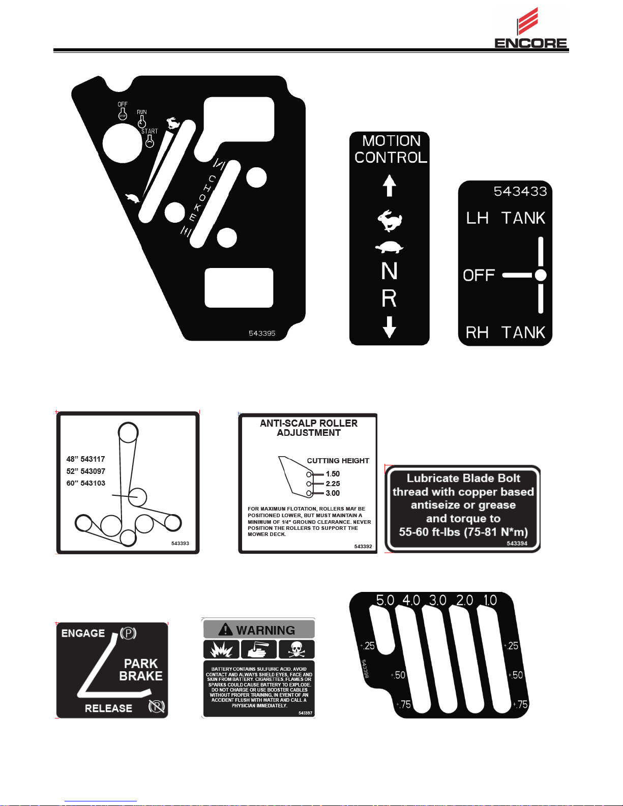
543395 8324 543433
543393 543392 543394
543391 543397 543398
12
Page 13

543396
543401
13
Page 14

52”
60”
Width without Deck
49.8”
55.0”
Width – Deflector Up
52.8”
61.1”
Width – Deflector Down
65.4”
73.6”
Length
76.6”
79.4”
Height – ROPS Up
68.6”
68.6”
Height – ROPS Down
46.6”
46.6”
Wheelbase
47.0”
49.75”
Curb Weight
1112
1051
SPECIFICATIONS
MODEL NUMBER
EC52FX730V3
EC52FX730V3CA
EC60FX730V3
EC60FX730V3CA
EC52FX730V5
EC52FX730V5CA
EC60FX801V5
EC60FX801V5CA
WEIGHT & DIMENSIONS
Battery Voltage:12V DC
Polarity: Neg. Ground
Fuses: (2) 20A
TRANSMISSION
Two Hydro Gear® integrated transaxles
Hydraulic Oil: 20w-50 Non- Synthetic
Speed:
o ZT-3400
0-9.6 mph Fwd
0-5.0 mph Reverse
o ZT-5400
0-12.0 mph Fwd
0-5.0 mph Reverse
CUTTING DECK
Cutting Width: 52” or 60”
Discharge: Side
Blade Size: 52”:18” ; 60”:20.5” (3 ea)
Deck Drive: Electric Clutch
Deck: 7 ga Welded Steel Floating Deck
Deck Depth: 5.5”
Cutting Height 1.0” to 5.5”Adjustment:
Mulching Kit: Optional
ENGINE
Kawasaki FX730V
Kawasaki FX801V
Specs: See your Engine Owner’s Manual
RPM: High Idle: 3600
Low Idle: 1550
FUEL SYSTEM
Capacity: 14 Gal
Type of Fuel: Regular Unleaded Gasoline
87 Octane or higher
Fuel Filter: In-line
ELECTRICAL SYSTEM
Charging System: 12 Volt, 15 Amp @
3600 RPM
Battery Type: Group Ul
Battery Class: 350 CCA Minimum
TIRES
Front: 13 x 6.50-122 Smooth
Pressure 12-14 psi (83-97 kPa)
Rear: WYK52FX730V5 (CA) – 24 X 9.5-12
EC60FX801V5 – 24 X 12.0-12
EC60FX801V5 (CA) ) – 24 X 12.0-12
Pressure 15 psi (103 kPa)
14
Page 15

OPERATION
OPERATOR CONTROLS
STEERING AND MOTION CONTROL:
The motion control levers control the forward
and reverse rotation of the respective tire.
Speed is proportional to amount the levers are
moved; moving the levers to the center (neutral)
position brakes the movement of the machine.
CHOKE CONTROL
The black paddle located on the control console.
The choke is used to aid in starting a cold
engine. Moving the choke lever forward will
move the choke into the “on” position, pulling
the choke lever back to the detent will return the
choke to the “off” position.
THROTTLE CONTROL
The red paddle located on the control console.
The throttle is used to control engine speed.
Moving the throttle lever forward will increase
engine speed and moving the throttle lever to
the rear will decrease engine speed. Moving
the throttle forward into the detent is full throttle.
SAFETY INTERLOCK
Pictorial indicators appear for the PTO, park
brake, drive levers, and operator
presence on the respective decals.
PTO must be disengaged, brake engaged,
and motion control levers out (neutral lock)
to start engine. (It is not necessary for the
operator to be in the seat to start the
engine.)
Operator must be in seat when PTO is
engaged, brake is disengaged, or motion
control levers are moved in or engine will
stop.
Engine will stop if either the left, the right, or
both levers are moved from neutral lock
position while brake is engaged.
PARK BRAKE LEVER
Located on left side of unit beside the LH
motion control lever.
To engage the brake, pull the lever
rearward.
To release, push the lever forward.
The unit must be tied down and brake
engaged when transporting.
Park brake must be disengaged before
moving.
15
Page 16

FUEL SHUT-OFF VALVE
Located on LH ROPS mount behind seat.
The fuel shut-off valve is used to shut off the
fuel when the machine will not be used for a
few days, during transport to and from the
jobsite, and when parked inside a building.
Align valve handle with the fuel line to open.
Rotate to horizontal position to close.
IGNITION SWITCH
Located on the control console.
The ignition switch is used to start and stop the
engine. The switch has three positions “OFF”,
“ON” and “START”. Insert key into switch and
rotate clockwise to the “ON” position. Rotate
clockwise to the next position to engage the
starter (key must be held against spring
pressure in this position). Allow the key to
return to the “ON” position immediately after the
engine starts.
WARNING
The engine and hydraulic drive units can
become very hot. Touching a hot engine or
hydraulic drive units can cause severe burns.
Allow the engine and hydraulic drive units to
cool completely before accessing the drive
wheel release valves.
ZT-3400 Hydro
Located on both sides of rear frame next to
engine.
To release drive wheels, pull wireform into short
leg of J-slot. To re-engage drive, return wire
form into long leg of J-slot
NOTE: To start the engine, the control levers
must be in the neutral positions, park brake
must be on, and blade switch must be off.
HOUR METER
Located on the control console
The hour meter records the number of hours
that the engine has run.
DRIVE WHEEL RELEASE VALVES
Drive wheel release valves are used to release
the hydrostatic drive system to allow the
machine to be moved by hand without the
engine running. Do Not tow machine
WARNING
Hands may become entangled in the rotating
drive components below the engine deck, which
could result in serious injury or death.
Stop engine, remove key, allow all the moving
parts to stop before accessing the drive wheel
release valves.
ZT-5400 Hydro
Located on inside face of hydro below the fan.
To release drive wheels, use a coin or flat
screwdriver to turn valve 90° clockwise.
To re-engage drive, turn valve 90° counterclockwise. Slot should be horizontal.
16
Page 17

DECK LIFT PEDAL
Located at the right front corner of the floor pan.
Push the pedal forward with your foot to raise
the cutting deck. Allow the pedal to move
rearward to lower the cutting deck to the cut
height that has been set.
TRANSPORT LOCK
PRE-START
Fill fuel tank on level ground. For best results
use only clean, fresh regular grade unleaded
gasoline with an octane rating of 87 or higher.
IMPORTANT: Never use methanol, gasoline
containing methanol, gasohol containing
more than 10% ethanol, premium gasoline,
or white gas because the fuel system could
be damaged.
Do Not add oil to gasoline
Do Not over fill fuel tank. Fill the fuel tank to
the bottom of the filler neck. The empty space
in the tank allows gasoline to expand.
Overfilling may result in fuel leakage or damage
to the engine or emission system.
Make sure you understand the controls, their
locations, their functions, and their safety
requirements.
Located at rear of height of cut plates on RH
side of floor pan. Transport pawl engages side
link when deck is raised to up-stop, preventing
deck from being lowered. To lower deck, apply
pressure to foot pedal, pull rearward on pawl
handle, and reduce pressure on foot pedal until
deck lowers to pre-selected cut height.
BLADE ENGAGEMENT SWITCH
Located on console.
Switch must be pulled out (up) to engage the
blades. Switch is pushed in to disengage the
blades.
Refer to the Maintenance section and perform
all the necessary inspection and maintenance
steps.
17
Page 18

OPERATING
INSTRUCTIONS
Perform daily maintenance
Check fuel level
Open Fuel valve
Adjust seat
RAISE THE ROLLOVER PROTECTION
STRUCTURE (ROPS)
IMPORTANT: The roll bar is an integral and
effective safety device. Keep the roll bar in
the raised and locked position when
operating the mower. Lower the roll bar
temporarily only when absolutely necessary.
STARTING THE ENGINE
1. Move both control levers to the neutral
position.
2. Pull the parking brake lever rearward to
engage the parking brake.
3. Push in (down) on the PTO switch to the
“disengage” position.
4. Place the throttle midway between the
“SLOW” and “FAST” positions.
5. On a cold engine, pull the choke lever up
into the “ON” position.
On a warm engine, leave the choke in the
“OFF” position.
6. Turn ignition switch to the “START” position.
Release the switch as soon as the engine
starts.
IMPORTANT: Do Not crank the engine
continuously for more than ten seconds
at a time. If the engine does not start,
allow a 60 second cool-down period
between starting attempts. Failure to
follow these guidelines can burn out the
starter motor.
BLADE ENGAGEMENT
DANGER
The rotating blades under the mower deck
are dangerous. Blade contact can cause
serious injury or death.
Do Not put hands or feet under the mower
or mower deck when the blades are
engaged.
DANGER
An uncovered discharge opening will allow
objects to be thrown in an operator’s or
bystander’s direction. Also, contact with
the blade could occur. Thrown objects or
blade contact can cause serious injury or
death.
Never operate the mower with the discharge
deflector raised, removed, or altered unless
there is a grass collection system or mulch
kit in place and working properly.
The PTO switch engages the cutting blades.
Be sure all persons are clear of mower deck
and discharge area before engaging the PTO.
1. Set throttle to an intermediate position
between slow and fast.
2. Pull up on the blade control switch (PTO).
The clutch should engage and the mower
blades begin rotating.
3. If engage PTO stalls engine, try partially
choking the engine. When PTO is engaged
return choke to OPEN.
4. Place the throttle in the “FAST” position to
begin mowing.
5. Disengage park brake before operating
machine.
7. If the choke is in the “ON” position,
gradually return choke to the “OFF”
position as the engine warms up.
18
Page 19

DISENGAGING THE BLADES
1. Set the throttle midway between the “SLOW”
and “FAST” positions.
2. Push down on the PTO switch to disengage
the blades.
STOPPING THE ENGINE
1. Bring the unit to a full stop.
2. Move the motion control levers to the
neutral position; move the control levers out
to the neutral lock position.
3. Engage the parking brake.
4. Push down on the PTO switch to disengage
the blades.
5. Place the throttle midway between the
“SLOW” and “FAST” positions.
6. Turn the ignition switch to the “OFF”
position to stop the engine.
7. Remove the key to prevent children or other
unauthorized persons from starting engine
8. Shut off fuel.
DRIVING THE MACHINE
TRAINING
Due to unique steering capabilities, zero turn
mowers are far more maneuverable than typical
riding mowers.
This section should be reviewed in its entirety
prior to attempting to move the mower under its
own power. When first operating the mower or
until becoming comfortable with controls, use a
reduced throttle speed and reduced ground
speed. DO NOT move control levers to the
furthest forward or reverse positions during
initial operation.
First time users should become familiar with the
mower’s movement on a hard surface, such as
concrete or blacktop PRIOR to attempting to
operate on turf. Until the operator becomes
comfortable with the mower controls and zero
turning capability, overly aggressive maneuvers
may damage turf.
Use slow and steady movement of the
control levers.
Use caution when making turns.
Slow the machine down before making
sharp turns.
IMPORTANT: To begin movement (forward
or backward) the operator must be in the
seat, the brake lever must be disengaged
(pushed down) before the motion control
levers can be moved in or the engine will
stop.
When the motion control levers are positioned
fully outward (apart) in the T-slot, the drive
system is in the neutral lock position (Figure 13).
When the motion control levers are moved
directly inward (together) the drive system is in
the neutral operate position.
DRIVING FORWARD
1. Release the parking brake.
2. Move motion control levers to neutral
operate position.
3. To move forward in a straight line, move
both levers forward with equal pressure.
To turn left or right, pull the motion control lever
back toward neutral in the desired turn direction.
The machine will move faster the farther the
motion control levers are moved from the
neutral position.
4. To stop, position both motion control levers
in the neutral operate position.
DRIVING IN REVERSE
1. Move the motion control levers to the
neutral operate position.
2. To move rearward in a straight line, slowly
move both levers rearward with equal
pressure.
CAUTION
Erratic movement of the control levers may
cause the Operator to lose control of the
machine, which may cause damage to the
machine or injury.
To turn left or right, release pressure on the
motion control lever toward the desired turn
direction.
3. To stop, position both motion control levers
in the neutral operate position.
19
Page 20

ADJUSTING THE CUTTING HEIGHT
The cutting height of the mower deck is
adjusted from 1.0 to 5.5 inches (2.5 cm to 14.0
cm) in 1/4 inch (6.4 cm) increments.
1. Stop the machine and move the motion
control levers to the neutral position.
2. Disengage the PTO.
3. Raise and lock the deck to the 5-1/2 inch
(14 cm) transport position.
The deck is raised by pushing the foot
operated deck lift pedal forward. The pedal
is located at the front right corner of the floor
pan.
Note: When changing the cutting height
positions, always come to a complete
stop and disengage the PTO.
4. Stop the engine, remove the key and wait
for all moving parts to stop.
5. Place the rollers in one of the positions
shown. Rollers will maintain 3/4 inch (19
mm) clearance to the ground to minimize
gouging and roller wear or damage.
For cutting heights above 3.5 inches (90 mm)
use the bottom hole. The rollers will still be
effective against scalping.
4. Insert the height adjustment pin into the
hole corresponding to the desired cutting
height.
See the decal on the side of the deck lift
plate for cut heights.
5. Push the deck lift pedal, hold back the
transport pawl handle and allow the deck to
lower to the cutting height.
ADJUSTING THE ANTI-SCALP ROLLERS
It is recommended to change the anti-scalp
roller position, when the height of cut has
changed.
1. Stop the machine and move the motion
control levers outward to the neutral locked
position.
2. Disengage the PTO.
3. Engage the park brake.
For Maximum Deck flotation, place the rollers
one hole position lower. Rollers should
maintain 1/4 (6.4 mm) clearance to the ground.
Do Not adjust the rollers to support the deck.
Note: The foot operated deck lift assist lever
can be used to momentarily lift the deck to clear
objects. Be sure that PTO is disengaged.
20
Page 21

TRANSPORTING
TRANSPORTING A UNIT
Use a heavy-duty trailer or truck to transport the
machine. Lock brake and block wheels.
Securely fasten the machine to the trailer or
truck with straps, chains, cable, or ropes. Be
sure that the trailer or truck has all necessary
lighting and marking as required by law.
Secure a trailer with a safety chain.
CAUTION
This unit does not have proper turn signals,
lights, reflective markings, or a slow moving
vehicle emblem. Driving on a street or
roadway without such equipment is
dangerous and can lead to accidents
causing personal injury. Driving on a street
or roadway without such equipment may
also be a violation of State laws and the
operator may be subject to traffic tickets
and/or fines.
Do Not drive a unit on a public street or
roadway.
Avoid sudden acceleration while driving
unit forward up a ramp to avoid tipping
backward.
Avoid sudden deceleration while backing
unit down a ramp to avoid tipping
backward.
LOADING A UNIT
Use extreme caution when loading units on
trailers or trucks. Backing unit onto trailer or
truck is recommended practice to avoid
rearward tip-over. However, condition such as
ramp angle and surface slickness can prevent
adequate drive wheel traction to accomplish
this. One full width ramp that is wide enough to
extend beyond the rear tires is recommended
instead of individual ramps for each side of the
unit. The lower rear section of the tractor frame
extends back between the rear wheels and
serves as a stop for tipping backward. Having
a full width ramp provides a surface for the
frame members to contact if the unit starts to tip
backward. If it is not possible to use one full
width ramp, use enough individual ramps to
simulate a full width continuous ramp.
WARNING
Loading a unit on a trailer or truck increases
the possibility of backward tip-over.
Backward tip-over could cause serious
injury or death.
Use extreme caution when operating a
unit on a ramp
Use only a single, full width ramp; Do
Not use individual ramps for each side of
the unit.
If individual ramps must be used, use
enough ramps to create an unbroken
ramp surface wider than the unit.
Do Not exceed a 15 degree angle
between ramp and ground or between
ramp and trailer or truck.
When possible, back machine onto
transport vehicle to avoid a rearward tipover.
Ramp should be long enough so that the angles
between the ramp and the ground and the ramp
and the trailer or truck do not exceed 15
degrees. A steeper angle may cause mower
deck components to get caught as the unit
moves from ramp to trailer or truck. Steeper
angles may also cause the unit to tip backward.
If loading on or near a slope, position the trailer
or truck so it is on the down side of the slope
and the ramp extends up the slope. This will
minimize the ramp angle. The trailer or truck
should be as level as possible.
IMPORTANT: Do Not attempt to turn the
unit while on the ramp, you may lose control
and drive off the side.
Avoid sudden acceleration when driving up a
ramp and sudden deceleration when backing
down a ramp. Both maneuvers can cause the
unit to tip backward.
21
Page 22

MAINTENANCE
Note: The left and right side of the machine is determined by sitting in the normal operator’s
position.
WARNING
Remove the key from the ignition switch,
engage parking brake, and pull the wire(s)
off the spark plug(s) before you do any
maintenance. Also push the wire(s) aside
so accidental contact with the spark plug
does not occur.
While maintenance or adjustments are being
made, someone could start the engine.
Accidental starting of the engine could
seriously injure you or other bystanders.
WARNING
Allow the engine to cool completely before
service or making repairs around the engine
area.
The engine can become very hot. Touching
a hot engine can cause severe burns.
22
Page 23

Maintenance Service Interval
Maintenance Procedure
Before each use or daily
Check the engine oil level
Check the mower blades
Check the safety interlock system
Check seat belt
Check for loose hardware
Check for belt obstructions
Check for fuel and oil leakage
Clean the engine and exhaust system area
Clean the grass and debris build-up from the machine and
cutting deck, including under the deck
After the first 8 hours
Change the engine oil
After the first 100 hours
Torque the wheel lug nuts
Change the hydraulic filter and fluid (20W50 engine oil)
Every 40 hours
Check the hydraulic oil level
Check the condition of the belts
Check the tire pressures
Lubricate the caster wheel bearings
Lubricate strut arms
Every 100 hours
Clean dust and dirt from cylinder and cylinder head fins
Change engine oil
Check V-Belts
Clean and regap spark plugs
Every 200 hours
Check front caster wheel rotation
Change engine oil filter
Every 250 hours
Replace the primary air cleaner
Check secondary air cleaner – replace if dirty. See the
Engine manual for additional information
Every 400 hours
Change hydro oil and filter
Every 500 hours
Check the wheel hub torque
Torque the wheel lug nuts
Replace the secondary air cleaner. See the Engine manual
for additional information.
Monthly
Check the battery charge
Yearly
Grease the front caster pivots
RECOMMENDED MAINTENANCE SCHEDULE(S)
23
Page 24

Voltage
Reading
Percent
Charge
Maximum
Charger
Settings
Charging
Interval
12.6 or
greater
100%
16 volts/7
amps
No
Charging
Required
12.4 – 12.6
75%-100%
16 volts/7
amps
30 Minutes
12.2 – 12.4
50- 75%
16 volts/7
amps
1 Hour
12.0 – 12.2
25 – 50%
14.4 volts/4
amps
2 Hours
11.7 – 12.0
0 – 25%
14.4 volts/4
amps
3 Hours
11.7 or less
0%
14.4 volts/2
amps
6 Hours or
More
CHECK ENGINE OIL LEVEL
Check the engine oil daily before starting the
engine otherwise shortage of the engine oil may
cause serious damage to the engine such as
seizure.
Allowing batteries to stand for an extended period
of time without recharging them will result in
reduced performance and service life. To preserve
optimum battery performance and life, recharge
batteries in storage when the open circuit voltage
drops to 12.4 volts.
Place the engine on a level surface. Clean
area around the oil gauge before removing it.
Remove the oil gauge and wipe it with a clean
cloth.
Reinsert the oil gauge to check the oil level.
The level should be between “ADD” and “FULL”
marks. Do not overfill.
Install and tighten the oil gauge
NOTE: To prevent damage due to freezing, battery
should be fully charged before putting away for
winter storage.
Check the voltage of the battery with a digital
voltmeter. Locate the voltage reading of the battery
in the table and charge the battery for the
recommended time interval to bring the charge up
to a full charge of 12.6 volts or greater.
CAUTION
Do not fill above the “FULL” mark. Excess oil
will cause a smoking condition, and may cause
the engine to overheat.
CHECK BATTERY CHARGE
Service Interval: Monthly
IMPORTANT INFORMATION
Do not attempt to open or remove caps or
covers. Adding or checking level of electrolyte
is not necessary.
Always use two wrenches for the terminal
screws.
WARNING
Do not short battery terminals by allowing a
wrench or any other object to contact both
terminals at the same time. Before connecting
battery, remove metal bracelets, wristwatch
bands, rings, etc.
IMPORTANT: Make sure the negative battery
cable is disconnected and the battery charger
used for charging the battery has an output of
16 volts and 7 amps or less to avoid damaging
the battery (see chart for recommended charger
settings).
Positive terminal must be connected first to
prevent sparks from accidental grounding.
WARNING
CALIFORNIA PROPOSITION 65
BATTERY POSTS, TERMINALS, AND RELATED
ACCESSORIES CONTAIN LEAD AND LEAD
COMPOUNDS, CHEMICALS KNOWN TO THE
STATE OF CALIFORNIA TO CAUSE CANCER
AND REPRODUCTIVE HARM. WASH HANDS
AFTER HANDLING.
24
Page 25

RECOMMENDED JUMP STARTING
PROCEDURE
Service Interval: As required
1. Check the weak battery for terminal corrosion
(white, green, or blue “snow”), it must be
cleaned off prior to jump starting, Clean and
tighten connections as necessary
CAUTION
Corrosion or loose connections can cause
unwanted electrical voltage spikes at anytime
during the jump starting procedure.
Do Not attempt to jump start with loose or
corroded battery terminals or damage to the
engine may occur.
WARNING
Batteries contain acid and produce explosive
gasses.
Shield the eyes and face from the batteries
at all times.
Do Not lean over the batteries.
NOTE: Be sure the vent caps are tight and level.
Place a damp cloth, if available, over any vent caps
on both batteries. Be sure the vehicles do not
touch and that both electrical systems are off and at
the same rated system voltage. These instructions
are for negative ground systems only.
DANGER
Jump starting a weak battery that is cracked,
frozen, has low electrolyte level, or an
open/shorted battery cell, can cause an
explosion resulting in serious personal injury.
Do Not jump start a weak battery if these
conditions exist.
2. Make sure the booster is a good and fully
charged lead acid battery at 12.6 volts or
greater. Use properly sized jumper cables (4 to
6 AWG) with short lengths to reduce voltage
drop between systems. Make sure the cables
are color coded or labeled for the correct
polarity.
CAUTION
Connecting the jumper cables incorrectly
(wrong polarity) can immediately damage the
electrical system.
3. Connect the positive (+) cable to the positive (+)
terminal of the discharged battery.
4. Connect the other end of the positive cable to
the positive terminal of the booster battery.
5. Connect the black negative (-) cable to the
other terminal (negative) of the booster battery.
6. MAKE THE FINAL CONNECTION ON THE
ENGINE BLOCK OF THE STALLED VEHICLE
(NOT TO THE NEGATIVE POST) AWAY
FROM THE BATTERY. STAND BACK.
7. Start the vehicle and remove the cables in the
reverse order of connection (the engine block
(black) connection is the first to disconnect).
Be certain of battery terminal polarity and
jumper cable polarity when hooking up
batteries.
NOTE: The following instructions are adapted from
the SAE J1494 Rev. Dec. 2001 – Battery Booster
Cables – Surface Vehicle Recommended Practice
(SAE – Society of Automotive Engineers).
25
Page 26

CHECK MOWER BLADES
Service Interval: Before each use or
daily
Stop engine, wait for all moving parts to stop,
and remove key. Engage parking brake.
1. Lift deck and secure in raised position as
stated in the Clean Grass Build-Up Under
Deck section.
2. Inspect blades and sharpen or replace as
required.
3. Reinstall the blades (if they were removed)
in the following order:
A. Install bushing through blade with
flange on bottom (grass) side of blade.
B. Install the bushing and blade onto
spindle.
C. Apply lubricant to threads of blade bolt
as needed to prevent seizing. Copperbased anti-seize preferable. Grease
acceptable substitute. Install blade bolt
finger tight then torque the blade bolts to
50-60 ft-lb (68-81 N-m).
WARNING
Incorrect installation of the blade or
components used to retain the blade can be
dangerous. Failure to use all original
components and assembled as shown could
allow a blade or blade component to be
thrown out from under the deck resulting in
serious personal injury or death.
Always use original equipment, i.e. blades,
blade bushings, and blade bolts as shown.
WARNING
Blades are sharp. Protect your hands
with gloves and/or wrap blades with a
heavy cloth when handling.
CHECK SAFETY INTERLOCK SYSTEM
Service Interval: Before each use or
daily
CAUTION
It is essential that operator safety
mechanisms be connected and in proper
operating condition prior to use.
Do not tamper with the interlock
switch.
Check the operation of the interlock
switches daily and replace any
damaged switches before operating
the machine.
Note: To prevent engine cut-outs on rough
terrain the seat kill switch has a 1/2 second
delay.
1. Check starting circuit. Starter should crank
with parking brake engaged, PTO
disengaged and motion control levers
moved out in the neutral lock position. The
operator does not need to be in the seat to
start the engine.
Try to start with operator in seat, parking
brake disengaged, PTO disengaged and
motion control levers in the neutral lock
position – starter must not crank.
Try to start with operator in seat, parking
brake engaged, PTO engaged and motion
control levers in the neutral lock position –
starter must not crank.
Try to start with operator in seat, parking
brake engaged, PTO disengaged, and the
left motion control lever in, starter must
not crank, repeat again with the right lever
in, then with both levers in – starter must
not crank.
2. Check the kill circuits. Run engine at onethird throttle, disengage parking brake and
raise off of seat (but do not get off of
machine) engine must initiate shutdown
after approximately 1/2 second has elapsed
26
Page 27

(seat has time delay kill switch to prevent
cut-outs on rough terrain).
Run engine at one-third throttle, engage
PTO and raise off of seat (but do not get
off of machine) engine must initiate
shutdown after one second has elapsed if
the handles are in. The delay will be 1/2
second if the handles are out.
Run engine at one-third throttle, with brake
disengaged, move levers in and raise off
seat (but do not get off of machine) engine
must initiate shutdown after 1/2 second
has elapsed.
Again, run engine at one-third throttle, brake
engaged, and move left motion control
lever in – engine must initiate shutdown
after 1/2 second has elapsed.
Repeat again moving the right lever in,
then moving both levers in – engine must
initiate shutdown after 1/2 second has
elapsed whether operator is on seat or not.
Note: If machine does not pass any of
these tests, do no operate. Contact
your authorized Worldlawn service
dealer.
Important: It is essential that
operator safety mechanisms be
connected and in proper operating
condition prior to use for mowing.
CHECK ROPS
Service Interval: Before each use or daily
Check that mounting hardware is tight. Make
sure pins are fully engaged and secured with
cotter hairpins.
CHECK SEAT BELT
Service interval: Before each use or daily
Visually inspect seat belt for wear, cuts, and
proper operation of retractor and buckle.
Replace before operating if damaged.
CHECK FOR LOOSE HARDWARE
Service Interval: Before each use or
daily
1. Stop engine, wait for all moving parts to
stop and remove key. Engage parking
brake.
2. Visually inspect machine for any loose
hardware or any other possible problem.
Tighten hardware or correct problem before
operating.
SERVICE AIR CLEANER
Service Interval: 250 Hours
1. Stop engine, wait for all moving parts to
stop and remove key. Engage parking
brake.
2. See the Engine Owner’s Manual for
maintenance instructions.
CHANGE ENGINE OIL
Service Interval: 100 hours
NOTE: Change oil and filter after first
eight (8) hours of operation.
1. Stop engine, wait for all moving parts to
stop and remove key. Engage parking
brake.
2. Drain oil while engine is warm.
3. The oil drain valve is located on the RH side
of the engine. Place the pan under the
machine to catch the oil. Loosen the oil
drain valve and allow the oil to drain.
Tighten the oil drain valve .
4. Clean around oil fill cap and remove cap.
Fill to specified capacity and replace cap.
5. Use oil recommended in the Engine
Owner’s Manual. DO NOT overfill. Wipe up
any spilled oil from engine deck mounting
surfaces.
6. Start the engine and check for leaks. Stop
engine and recheck oil level.
27
Page 28

FITTING
LOCATIONS
INITIAL
PUMPS
NUMBER
OF
PLACES
SERVICE
INTERVAL
1. Deck Struts
1 2 Yearly
2. Front Caster
Wheel Hubs
1 2 Weekly
3. Front Caster
Pivots
0 2 Yearly
CHANGE ENGINE OIL FILTER
Service Interval: 200 hours
1. Follow steps 1 through 3 above for engine
oil change
2. Replace the oil filter per the engine Owner’s
Manual. Clean around the oil filter and
carefully remove the filter by unscrewing it.
Make sure no oil drains onto the belt drive
or clutch through the holes in the engine
deck. Before the new filter is installed,
apply a thin coating of oil on the surface of
the rubber seal. Turn filter clockwise until
rubber seal contacts the filter adapter, then
tighten filter and additional 2/3 to 3/4 turn.
3. Follow steps 4 through 6 above to refill
engine oil.
CHECK HYDRAULIC OIL LEVEL
Service Interval: Every 40 hours
1. Stop engine, wait for all moving parts to
stop and remove key. Engage parking
brake.
2. Clean area around hydraulic reservoir cap
and remover cap. Oil level should be
between 1/4” – 3/4” when cold. Lower
levels can result in hydro damage/failure.
Higher levels can result in spillage fom hot
oil expansion. If necessary, add SAE
20W50 motor oil. Replace hydraulic
reservoir cap and tighten until snug. Do not
over- tighten.
CHECK TIRE PRESSURES
Service Interval: Every 40 hours
CHECK CONDITION OF BELTS
Service Interval: Every 40 hours
1. Stop engine, wait for all moving parts to
stop and remove key. Engage parking
brake.
2. Look on the top side of the cutting deck to
check the mower blade drive belt condition.
3. Look under the engine deck to check the
pump drive belt condition.
4. Check all idler arms to be sure they pivot
freely.
LUBRICATE GREASE FITTINGS
Note: See chart for service intervals.
1. Stop engine, wait for all moving parts to
stop and remove key. Engage parking
brake.
2. Lubricate fittings with NGLI #2 multipurpose grease.
CASTER WHEEL ROTATION
Service Interval: Every 200 hours
Removal and Installation
Remove nut and caster bolt. Pull the wheel out
of the fork. Install in reverse order. Tighten
caster bolt. Torque to 45 ft-lbs (61Nm), then
back nut off 1/2 turn.
NOTE: Tire should rotate freely but axle
spacers should not.
If wheels do not rotate freely take the unit to the
dealer for service.
Lubrication Chart
1. Stop engine, wait for all moving parts to
stop and remove key. Engage parking
brake.
2. Check tire pressure.
3. Inflate drive tires to 12-14 psi (83-97 kPa).
4. Inflate caster tires to 15 psi.
28
Page 29

CHECK SPARK PLUGS
Service Interval: Every 100 Hours
Remove spark plugs, check condition and reset
gaps, or replace with new plugs. See Engine
Owner’s Manual.
CHANGE HYDRAULIC SYSTEM FILTER
AND FLUID
Service Interval: Every 400 Hours
ZT-3400
This transaxle is designed with an external filter
for ease of maintenance. To ensure constant
fluid quality levels and longer life, an initial oil
and filter change at 75-100 hours, then every
400 hours thereafter is recommended.
The following procedure can be performed with
the transaxles installed in the vehicle, and the
vehicle on level ground. Apply the bypass
valve for each transaxle and lock the vehicle
parking brake.
1. Remove the three 1/4” filter guard screws
and filter guard. Clean any loose debris
from around the perimeter of the filter. See
figure below.
2. Place an oil drain pan (12” or more diameter
and 8 qt. capacity is optimal) beneath the oil
filter. Remove the oil filter from the
transaxle.
3. After the oil has drained, wipe the filter base
surface off and apply a film of new oil to the
gasket of the new replacement filter (HydroGear part number 52114).
4. Install the new filter by hand, turn 3/4 to one
full turn after the filter gasket contacts the
filter base surface.
5. Re-install the filter guard with three 1/4”
screws. Torque screws to 65 in/lbs (7.3 Nm)
each.
6. Repeat steps 1-5 on the opposite side
transaxle drive.
7. Drain old oil filters of all free flowing oil prior
to disposal. Place used oil in appropriate
containers and deliver to an approved
recycling collection facility.
8. Remove the top port plug from the left side
and right side transaxles prior to filling with
oil. This will allow the transaxles to vent
during oil fill.
9. Remove the cap from the transaxle’s
expansion tank located on the vehicle frame.
10. Fill with 20W50 motor oil until oil just
appears at the bottom of each transaxle’s
top port (approximately 2 qts. Per transaxle,
4 qts. Total). Install the top port plug into
each transaxle as the oil level reaches this
port. See figure below.
11. Install and torque the top port plugs to 180
in/lbs (20.3 Nm).
12. Continue to fill the transaxles through the
expansion tank until the “Full Cold” line is
reached on the Hydro-Gear expansion tank.
13. Re-install the expansion tank cap by hand.
Be careful to not over-tighten.
14. Proceed to the purge procedure.
29
Page 30

5. Install the top oil fill vent port plug and
CAUTION
Raising the mower for service or
maintenance relying solely on
mechanical or hydraulic jacks could be
dangerous. The mechanical or hydraulic
jacks may not be enough support or
may malfunction allowing the unit to fall,
continue filling the system with oil until the
fill line is reached in the expansion tank.
6. Drain old oil filter of all free flowing oil prior
to disposal. Place used oil in appropriate
containers and deliver to an approved
recycling collection facility.
7. Proceed to the purge procedure.
which could cause injury.
Do not rely solely on mechanical or
hydraulic jacks for support. Use
adequate jack stands or equivalent
support.
ZT-5400
This transaxle is designed with a serviceable
filter. To ensure constant fluid quality levels
and longer life, an initial oil and filter change at
10 hours is recommended. Subsequent
changes are recommended at 400 hour
intervals minimum, or yearly, whichever comes
first.
The following procedure can be performed with
the transaxle installed in the vehicle, and the
vehicle on level ground. Apply the bypass
valve and lock the vehicle parking brake.
1. Place an oil drain pan (12” or more in
diameter and 8 qt. capacity is optimal)
beneath the oil filter. Remove the oil filter
cover from the transaxle to drain the oil.
Remove the O-ring from the cover and
discard the O-ring.
2. After the oil has drained from the transaxle,
remove the oil filter from the transaxle
housing.
3. Install a new filter (Hydro-Gear part number
71943). Install a new O-ring onto the filter
cover and install the filter cover. See figure
below. Torque to 480-580 in-lbs [54.23-
65.53 Nm]
4. Remove the top oil fill vent port plug and fill
the transaxle with new 20W50 motor oil
through the expansion tank port/fill port until
oil reaches the oil fill vent port.
HYDRAULIC SYSTEM AIR PURGE
Service Interval: As Required
Due to the effects air has on efficiency in
hydrostatic drive applications, it is critical that
air is removed or purged from the system.
These purge procedures must be preformed
anytime a hydrostatic system has been opened
for maintenance or repair, or if any additional oil
has been added to the system.
Air creates inefficiency because it has
compression and expansion rates that are
higher than that of oil.
Air trapped in the oil may cause the following
symptoms:
Noisy operation.
Lack of power or drive after short-term
operation.
High operation temperature and excessive
expansion of oil.
Before starting make sure the reservoir is at the
proper oil level. If it is not, fill to the vehicle
manufacturer’s specifications.
30
Page 31

The following procedures should be performed
with the vehicle drive wheels off the ground,
then repeated under normal operating
conditions.
WARNING
POTENTIAL FOR SERIOUS INJURY
Certain procedures required the vehicle
engine to be operated and the vehicle to be
raised off of the ground. To prevent
possible injury to the servicing technician
and/or bystanders, insure the vehicle is
properly secured.
1. With the bypass valve open, (see Drive
Wheel Release in the Operation section)
and the engine running, slowly move the
directional control in both forward and
reverse directions (5 to 6 times). As air is
purged from the unit, the oil level in the
reservoir will drop.
2. With the bypass valve closed and the
engine running, slowly move the directional
control in both forward and reverse
directions (5 to 6 times). Check the oil level,
and add oil as required after stopping
engine.
3. It may be necessary to repeat steps 1 and 2
until all the air is completely purged from the
system. When the drive wheels rotate
forward and reverse at normal speed and
the reservoir oil remains at a constant level,
purging is complete.
THREAD LOCKING ADHESIVES
Thread locking adhesives such as “Loctite 242”
or “Fel-Pro, Pro-lock nut type” are used on the
following fasteners:
1. Clutch retaining bolt in end of engine
crankshaft.
COPPER-BASED ANTI-SEIZE
Copper-based anti-seize can be used in the
following locations:
1. On threads of Blade Bolts. See Check
Mower Blades section.
2. Between engine crankshaft, pump drive
sheave, and clutch.
DIELECTRIC GREASE
Dielectric grease can be used on all blade
type electrical connections to prevent
corrosion and loss of contact.
CHECK V-BELTS
Service Interval: Every 100 Hours
Deck Belt Removal:
1. Stop engine
2. Lower deck to lowest position
3. Remove belt shields
4. Place ratchet strap hook in notch on deck
idler arm (Loc A in Figure) and in hole in the
RH lower strap (Loc B in Figure)
5. Tighten ratchet strap to rotate idler arm and
relieve belt tension.
6. Remove deck belt
Deck Belt Installation
1. Perform steps 1-5 of Deck Belt Removal
2. Route belt onto deck sheaves and idlers.
Refer to routing decal located on cutting
deck
3. Roll belt onto clutch sheave
4. Loosen ratchet strap to return idler tension
to belt
5. Verify belt is routed properly and is seated
in all sheaves and idlers
6. Remove ratchet strap
7. Replace belt shields
31
Page 32

Pump Belt Removal:
1. Remove deck belt (see Deck Belt Removal)
2. Rotate idler arm to relieve belt tension. The
idler arm has a 1/2” square hole to accept a
1/2” breaker bar to gain leverage over the
spring.
3. Remove belt from engine and hydro
sheaves.
Note: Belt routed above park brake cross shaft.
It must pass between the shaft and clutch
housing. This necessitates the disconnection of
the clutch jumper harness from the clutch. It
may also be necessary to loosen or remove the
clutch anchor to allow the clutch to rotate
thereby creating more clearance to the cross
shaft.
Pump Belt Installation
1. From the rear of the machine, seat the belt
into engine sheave
2. Pass forward edge of belt up between the
cross shaft and clutch.
3. Route belt around hydro sheaves and
stationary idler (ZT-3400 models only).
4. Rotate idler arm and roll belt onto idler.
5. Re-install or re-tighten clutch anchor.
6. Reconnect jumper harness to clutch.
7. Re-install deck belt (see Deck Belt
Installation)
CASTER PIVOT BEARINGS PRE-LOAD
AND LUBRICATION
Service Interval: Once aYear
Tighten the nut until it is snug then back it off
1/8-1/4 turn. This will set the preload on the
bearing. You should feel a slight drag as you
rotate the caster fork clockwise and
counterclockwise
1. Remove the protective cap from the top.
2. Pump grease into the fitting until grease is
seen coming up through the bearing. Do no
over fill. Do not fill the housing.
3. Reinstall the protective cap and tap into
place
ADJUSTMENTS
Note: Disengage PTO, shut off engine, wait for
all moving parts to stop, engage parking brake,
and remove key before servicing, cleaning, or
making any adjustments to the unit.
CAUTION
Raising the mower for service or
maintenance relying solely on
mechanical or hydraulic jacks could be
dangerous. The mechanical or hydraulic
jacks may not be enough support or
may malfunction allowing the unit to fall,
which could cause injury.
Do Not rely solely on mechanical or
hydraulic jacks for support. Use
adequate jack stands or equivalent
support.
DECK LEVELING
Note: Small adjustments can be accomplished
by increasing the tire pressure in the tire on the
low side.
1. Park the machine on a level surface and
disengage the blade control switch.
2. Stop engine, wait for all moving parts to
stop, and remove key. Engage parking
brake.
3. Check the air pressure in the drive tires. If
needed, adjust to the recommended
inflation; refer to Checking the Tire
Pressure in the Drive System Maintenance
section.
4. Set the height of cut to the desired position.
5. Raise the discharge deflector.
6. Carefully rotate the blades front to rear.
Measure from the tip of the front blade to
the level surface.
NOTE: In most conditions, the back tips should
be adjusted 1/4 inch (6.4 mm) higher than the
fronts.
32
Page 33

7. Fine tune the front deck lift assembly by
loosening adjuster jam nut, then loosen nut
on upper bolt that connect chain to lift arm.
(no more than 1/4 turn), then turn the
adjustment screw until blade is at the
correct height.
8. Fine tune rear adjusters as required. The
single point adjustment can be utilized to
gain more adjustment.)
9. Re-measure until all four sides are the
correct height. Tighten all the nuts on the
deck lift arm assemblies.
10. Lower discharge deflector.
14. Re-tighten front and rear height-of-cut plate
mounting bolts.
Important: Torque the front and rear
height-of-cut plate mounting bolts to 2733 ft-lb (37-45 N-m).
15. Repeat steps 6 through 10.
PUMP DRIVE BELT TENSION
Self-tensioning – No adjustment necessary.
11. If the four deck links do not have enough
adjustment to achieve accurate cut height
with the desired rake, the single point
adjustment can be utilized to gain more
adjustment
12. To adjust the single point system, first
loosen the front and rear height-of-cut plate
mounting bolts.
13. If the deck is too low, tighten the single point
adjustment bolt by rotating it clockwise. If
the deck is too high, loosen the single point
adjustment bolt by rotating it
counterclockwise.
Note: Loosen or tighten the single point
adjustment bolt enough to move the heightof-cut plate mounting bolts at least 1/3 the
length of the available travel in their slots.
This will regain some up and down
adjustment on each of the four deck links.
MOWER DECK DRIVE BELT TENSION
Self-tensioning – No adjustment necessary.
PARK BRAKE ADJUSTMENT
Check to make sure brake is adjusted properly.
This procedure must be followed after the first
100 hours or when a brake component has
been removed or replaced.
1. Drive the machine onto a level surface.
2. Disengage the blade control switch (PTO),
move the motion control levers to the
neutral locked position and set the parking
brake.
3. Stop the engine, wait for all moving parts to
stop and remove the key.
4. Raise the back of the machine up and
support the machine with jack stands.
CAUTION
Raising the mower for service or
maintenance relying solely on
mechanical or hydraulic jacks could be
dangerous. The mechanical or hydraulic
jacks may not be enough support or
may malfunction allowing the unit to fall,
which could cause injury.
33
Page 34

Do Not rely solely on mechanical or
hydraulic jacks for support. Use
adequate jack stands or equivalent
support.
5. Lift park brake lever and hold in engaged
position.
6. Tighten brake spring nut on RH link
assembly until the swivel separates from
retainer. Use a feeler gage to detect when
this gap occurs.
7. Repeat step 6 for the LH side.
8. Disengage and re-engage park brake.
9. Repeat steps 6 and 7.
10. Remove jack stands.
MOTION CONTROL LINKAGE
ADJUSTMENT
Located on either side of the fuel tank, below
the seat are the pump control linkages.
Rotating the pump linkage with a 1/2 inch
wrench allows fine tuning adjustments so that
the machine does not move in neutral. Any
adjustments should be made for neutral
position only.
WARNING
Engine must be running and drive wheels
must be turning so adjustments can be
performed. Contact with moving pars or hot
surfaces may cause personal injury.
4. Temporarily install a jumper wire across
the terminals in the connector of the main
wiring harness.
5. Start engine. Brake must be engaged and
motion control levers out to start engine.
Operator does not have to be in the seat
because of the jumper wire being used.
Run engine at full throttle and release brake.
6. Run the unit at least 5 minutes with the
drive levers at full forward speed to bring
hydraulic oil up to operating temperature.
Note: The motion control lever needs to be
in neutral while making any necessary
adjustments
7. Bring the motion control levers into the
neutral position. Adjust pump control rod
lengths by rotating the double nuts on the
rod in the appropriate direction until the
wheels slightly creep in reverse. See figure
below. Move the motion control levers to
the reverse position and while applying
slight pressure to the lever allow the RTN
springs to bring the levers back to neutral.
The wheels must stop turning or slightly
creep in reverse.
Keep fingers, hands, and clothing clear of
rotating components an hot surfaces.
1. Prior to starting the engine, push the deck
lift pedal and remove the height of cut pin.
Lower deck to the ground.
2. Raise the rear of machine up and support
with jack stands (or equivalent support) just
hight enough to allow drive wheels to turn
freely.
3. Remove the electrical connection from the
seat safety switch, located under the bottom
cushion of the seat. The switch is a part of
the seat assembly.
8. Shut off unit. Remove jumper wire from
wire harness and plug connector into seat
switch.
9. Remove the jack stands.
10. Raise the deck and re-install the height of
cut pin.
11. Check that the machine does not ccreep in
neutral with the park brakes disengaged.
34
Page 35

NEUTRAL ADJUSTMENT
If the hydro RTN requires adjustment, please
refer to the appropriate Hydro Gear service
manual for adjustment procedure.
MOTION CONTROL DAMPER
ADJUSTMENT
Two positions are provided for installing the
forward damper stud to the motion control
assembly. The upper hole provides less
resistance, the lower provides more.
MOTION CONTROL HANDLE
ADJUSTMENT
Adjusting the height:
The motion control levers can be adjusted
highter or lower for maximum operator comfort.
1. Remove the two bolts holding the control
lever to the control arm shaft (A)
2. Move the control lever to the next set of
holes (B). Secure the lever with the two
bolts.
3. Repeat the adjustment for the opposite
control lever.
MOTION CONTROL NEUTRAL LOCK
PIVOT ADJUSTMENT
The flanged nut can be adjusted to obtain a
more desired motion control lever resistance
Tighten or loosen the upper flanged nut to the
desired feel.
For more resistance, tighten the flanged nut.
For less resistance, loosen the flanged nut.
Adjusting the Tilt
The motion control levers can be tilted fore or
aft for maximum operator comfort.
1. Loosen the upper bolt holding the control
lever to the control arm shaft.
2. Loosen the lower bolt just enough to pivot
the control lever fore or aft. Tighten both
bolts to secure the control in the new
position.
3. Repeat the adjustment for the opposite
control lever.
35
Page 36

CLEANING
Service Interval: Before each use or daily
(May be required more often in dry or dirty
conditions.)
CAUTION
Excessive debris around engine cooling air
intake and exhaust system area can cause
engine exhaust area and hydraulic system
to overheat which can create a fire hazard.
CLEAN ALL DEBRIS FROM ENGINE AND
EXHAUST SYSTEM AREA.
1. Stop engine, wait for all moving parts to
stop, and remove key. Engage parking
brake.
2. Clean all debris from rotating engine air
intake screen around engine shrouding, and
exhaust system area.
3. Wipe up any excessive grease or oil around
the engine and exhaust system area.
CLEAN DEBRIS FROM MACHINE
Service Interval: Before each use or daily
1. Stop engine, wait for all moving parts to
stop, and remove key. Engage parking
brake.
2. Clean off any oil, debris, or grass build-up
on the machine and cutting deck, especially
under deck belt shields, around the fuel tank,
around engine and exhaust area.
CLEAN GRASS BUILD-UP UNDER DECK
Service Interval: Before each use or daily
1. Stop engine, wait for all moving parts to
stop, and remove key. Engage parking
brake.
2. Raise deck to the transport (maximum
cutting height) position. Lift the front of unit
and support unit using jack stands or
equivalent support.
CAUTION
CLEAN DUST AND DIRT FROM
CYLINDER HEAD FINS.
Service Interval: Every 100 hours
1. Stop engine, wait for all moving parts to
stop, and remove key. Engage parking
brake.
2. Remove cooling shrouds from engine and
clean cooling fins. Also clean dust, dirt and
oil from external surfaces of engine which
can cause improper cooling.
3. Make sure cooling shrouds are properly
reinstalled. Operating the engine without
cooling shrouds will cause engine damage
due to overheating.
Raising the mower for service or
maintenance relying solely on
mechanical or hydraulic jacks could be
dangerous. The mechanical or hydraulic
jacks may not be enough support or
may malfunction allowing the unit to fall,
which could cause injury.
Do not rely solely on mechanical or
hydraulic jacks for support. Use
adequate jack stands or equivalent
support.
3. Clean out any grass build-up from
underside of deck and in discharge deflector.
36
Page 37

PROBLEM
POSSIBLE CAUSE
Engine will not start
Contamination in the carburetor or fuel line.
Fuel supply is closed or the tap for the fuel
tank is in the wrong position.
Clogged fuel filter or fuel line.
Faulty ignition system.
Starter does not turn the engine over.
Blade switch is engaged.
Steering controls are not locked in the neutral
position
Parking brake is not activated.
Dead battery.
Poor contacts on the battery terminal cable
connections.
Fuse blown.
Ignition system faulty.
Fault in the starter safety circuit See Safety
Interlock System in the Maintenance section.
Engine runs rough.
Faulty carburetor.
Choke control is pulled out with warm engine.
Clogged fuel filter or jet.
Clogged ventilation valve on the fuel cap.
Fuel tank nearly empty.
Fouled spark plug.
Spark plug is loose.
Rich fuel mixture or fuel-air mixture (gasoline).
Wrong fuel type (gasoline).
Water in the fuel (gasoline).
Clogged air filter
TROUBLESHOOTING
IMPORTANT: It is essential that all operator safety mechanisms be connected and in proper operating
condition prior to mower use.
When a problem occurs, do not overlook the simple causes. For example, starting problems could be
caused by an empty fuel tank.
The following table lists some of the common causes of trouble. Do not attempt to service or replace
major items or any items that call for special timing of adjustments procedures. Have this work done by
your Service Dealer.
37
Page 38

PROBLEM
POSSIBLE CAUSE
Engine seems weak
Clogged air filter
Fouled spark plugs.
Carburetor incorrectly adjusted
Machine vibrates.
Blades are loose.
Blades are incorrectly balanced.
Engine is loose.
Engine overheats.
Clogged air intake or cooling fins.
Engine overloaded.
Poor ventilation around engine.
Defective engine speed regulator.
Too little or no oil in the engine.
Fouled spark plug.
Battery not charging.
Poor contact with battery terminal cable
connectors.
Charging lead is disconnected.
Machine moves slowly, unevenly, or not at all.
Parking brake on.
Bypass valve on pump open.
Drive belt for the transmission has slack or has
come off.
Air in hydraulic system.
Mower deck not engaging.
Drive belt for the mower deck has come loose.
Electric connection to clutch has loosened.
Blade switch is faulty or has come loose from
the cable contact.
Fuse has blown.
Hydraulic drive leaks oil.
Damaged seals, housing, or gaskets.
Air trapped in hydraulic system.
Uneven mowing results.
Unequal tire pressure on the left and right
sides.
Bent blades.
Suspension for the mower deck is uneven.
Blades are dull.
Driving speed too high.
Grass is too long.
Grass collected under the mower deck.
TROUBLESHOOTING
38
Page 39

STORAGE
WINTER STORAGE
The machine should be readied for storage at
the end of the mowing season, or if it will not be
in use for more than 30 days.
Fuel allowed to stand for long periods of time
(30 days or more) can leave sticky residues that
can plug the carburetor and disrupt engine
function.
Fuel stabilizers are an acceptable option as
regards to the sticky residues that can occur
during storage.
Add stabilizer to the fuel in the tank or in the
storage container. Always use the mixing
rations specified by the manufacturer of the
stabilizer. Run the engine for at least 10
minutes after adding the stabilizer so that it
reaches the carburetor. Do not empty the fuel
tank and the carburetor if a stabilizer has been
added.
To ready the machine for storage, follow these
steps:
1. Thoroughly clean the machine, especially
under the mower deck. Touch up damage
to the paint and spray a thin layer of oil on
the underside of the mower deck to avoid
corrosion.
2. Inspect the machine for worn or damaged
parts and tighten any nuts or screws that
may have become loose.
3. Change the engine oil; dispose of properly.
4. Empty the fuel tanks or add a fuel stabilizer.
Start the engine and allow it to run until the
carburetor is drained of fuel or the stabilizer
has reached the carburetor.
5. Remove the spark plug and pour about a
tablespoon of engine oil into the cylinder.
Turn over the engine so that the oil is evenly
distributed and then refit the spark plug.
6. Lubricate all grease zerks, joints, and axles.
7. Remove the battery. Clean, charge, and
store the battery in a cool place, but protect
it from direct cold.
8. Store the machine in a clean, dry place and
cover it for extra protection.
39
Page 40

WIRING SCHEMATICS
40
Page 41

EVAPORATIVE EMISSION CONTROL WARRANTY STATEMENT
CALIFORNIA EVAPORATIVE EMISSION CONTROL WARRANTY STATEMENT
YOUR WARRANTY RIGHTS AND OBLIGATIONS
The California Air Resources Board and Worldlawn Power Equipment is pleased to explain the
evaporative emission control system's warranty on your 2014 model year lawn mower. In California,
new equipment that use small off-road engines must be designed, built, and equipped to meet the
State's stringent anti-smog standards. Worldlawn Power Equipment must warrant the evaporative
emission control system on your lawn mower for the period listed below provided there has been
no abuse, neglect or improper maintenance of your equipment.
Your evaporative emission control system may include parts such as: fuel tanks, fuel lines, fuel
caps, valves, canisters, vapor hoses, clamps, connectors, and other associated components. For
engines less than or equal to 80 cc, only the fuel tank is subject to the evaporative emission
control warranty requirements of this section.
MANUFACTURER'S WARRANTY COVERAGE:
This evaporative emission control system is warranted for two years. If any evaporative emissionrelated part on your equipment is defective, the part will be repaired or replaced by Worldlawn
Power Equipment.
OWNER'S WARRANTY RESPONSIBILITIES:
• As the lawn mower owner, you are responsible for performance of the required maintenance
listed in your owner's manual. Worldlawn Power Equipment recommends that you retain all
receipts covering maintenance on your lawn mower, but Worldlawn Power Equipment cannot deny
warranty solely for the lack of receipts.
• As the lawn mower owner, you should however be aware that Worldlawn Power Equipment may
deny you warranty coverage if your fuel tank has failed due to abuse, neglect, or improper
maintenance or unapproved modifications.
• You are responsible for presenting your lawn mower to a Worldlawn Power Equipment
distribution center or service center as soon as the problem exists. The warranty repairs should be
completed in a reasonable amount of time, not to exceed 30 days. If you have a question regarding
your warranty coverage, you should contact Worldlawn Power Equipment service at (402) 228-
4255.
DEFECTS WARRANTY REQUIREMENTS:
(a) The warranty period begins on the date the engine or equipment is delivered to an ultimate
purchaser. 0
(b) General Evaporative Emissions Warranty Coverage. The fuel tank must be warranted to the
ultimate purchaser and any subsequent owner that the evaporative emission control system when
installed was:
(1) Designed, built, and equipped so as to conform with all applicable regulations; and
-,----"----- ----------~.
(2) Free from defects in materials and workmanship that causes the failure of a warranted part for
a period of two years.
(c) The warranty on evaporative emissions-related parts will be interpreted as follows:
(1) Any warranted part that is not scheduled for replacement as required maintenance in the
written instructions must be warranted for the warranty period defined in subsection (b)-(2). If any
such part fails during the period of warranty coverage, it must be repaired or replaced by
41
Page 42

Worldlawn Power Equipment. Any such part repaired or replaced under the warranty must be
warranted for a time not less than the remaining warranty period.
(2) Any warranted part that is scheduled only for regular inspection in the written
instructions must be warranted for the warranty period defined in subsection (b)-(2). A statement in
such written instructions to the effect of "repair or replace as necessary" will ,not reduce the period
of warranty coverage. Any such part repaired or replaced under warranty must be warranted for a
time not less than the remaining warranty period.
(3) Any warranted part that is scheduled for replacement as required maintenance in the
written instructions must be warranted for the period of time prior to the first scheduled
replacement point for that part. If the part fails prior to the first scheduled replacement, the part
must be repaired or replaced by Worldlawn Power Equipment. Any such part repaired or replaced
under warranty must be warranted for a time not less than the remainder of the period prior to the
first scheduled replacement point for the part.
(4) Repair or replacement of any warranted part under the warranty provisions of this article'
must be performed at no charge to the owner at a warranty station.
(5) Notwithstanding the provisions of subsection (4) above, warranty services or repairs
must be provided at distribution centers that are franchised to service the subject engines or
equipment.
(6) The owner must not be charged for diagnostic labor that leads to the determination that
a warranted part is in fact defective, provided that such diagnostic work is performed at a warranty
station.
(7) Throughout the evaporative emission control system's warranty period set out in
subsection (b)(2), Worldlawn Power Equipment must maintain a supply of warranted parts
sufficient to meet the expected demand for such parts.
(8) Manufacturer approved replacement parts must be used in the performance of any
warranty maintenance or repairs and must be provided without charge to the owner. Such use will
not reduce the warranty obligations of the manufacturer issuing the warranty.
(9) The use of any add-on or modified parts will be grounds for disallowing a warranty claim
made in accordance with this article. Worldlawn Power Equipment will not be liable under this
Article to warrant failures of warranted parts caused by the use of an add-on or modified part.
(10) Worldlawn Power Equipment shall provide any documents that describe the warranty
procedures or policies within five working days of request by the Air Resources Board.
EMISSION WARRANTY PARTS LIST:
1) Fuel Tank, 2) Fuel line, 3) Fuel cap, 4) remote vent, 5) Carbon canister
Written instructions for the maintenance and use of the evaporative emissions control system by
the owner shall be furnished with each new engine or equipment.
42
Page 43

Caliber EC52/60Mowers
LIMITED WARRANTY:
Encore, A division of Worldlawn, warrants that the EC52/60 mower (“Mower”), purchased from an Authorized Encore Dealer,
will be free from defects in material and workmanship for a period of three years commercial/residential from the original date
of purchase (see details below). Encore also warrants the Mower’s deck shell will be free from defects in material and
workmanship for a period of ten years commercial/residential from the original date of purchase (see details below). During the
limited warranty period, Encore will repair or replace, at its discretion, any Mower or part thereof which is found to be defective
in material and workmanship. This limited warranty specifically excludes wear items, included but not limited to belts, blades,
and tires. This limited warranty also specifically excludes parts covered by another manufacturer’s warranty, in which parts are
covered only by that manufacturer’s warranty. This limited warranty does not extend to the engine or the hydro’s which
are warranted separately by the engine manufacturer and hydro manufacturer
This limited warranty extends only to the original retail purchaser (“Owner”) of a Mower. This limited warranty may not
be assigned or transferred without prior express written consent of Encore. This limited warranty extends only to those Mowers
purchased for private residential and commercial use. A Mower purchased for any other reason, for example as a rental unit,
shall have a (90) day limited warranty under the same terms and conditions as set forth herein.
Proof of purchase will be required to substantiate all warranty claims. All warranty work must be performed by an Authorized
Encore Dealer. Any work done on or to the Mower by anyone other than an Authorized Encore Dealer, including the original
purchaser, voids all provisions of the warranty except those provisions which limit Encore’s liability (as set forth below).
Any Mower or part thereof which, in Encore’s sole discretion, is deemed defective shall be repaired or replaced, at Encore’s
option, without charge for parts or labor up to three years of the original date of purchase. Any Mower deck shell, in Encore’s
sole discretion, is deemed defective shall be repaired or replaced, at Encore’s option, without charge for parts or labor for the
first five years of the original date of purchase, and without charge for parts only for years six through ten from the original date
of purchase. To take advantage of this limited warranty, the Mower must be returned to an Authorized Encore Dealer within the
warranty period. The cost of delivering the Mower to the Authorized Dealer and return delivery shall be the
responsibility of the Owner.
Encore’s sole responsibility with any claim made under this warranty is limited only to repairing or replacing the Mower or a
defective part thereof, and no claim of breach of warranty shall be cause for rescission, cancellation, or voiding the contract of
sale of the Mower.
This limited warranty does not extend to any Mower or part thereof which has been misused, neglected, damaged, abused, not
properly installed or maintained, altered or which has been operated in any way contrary to the operating instructions as
specified in the Owner/Operator Manual. This limited warranty does not extend to any repair or replacement made necessary
by normal use.
THE WARRANTY EXPRESSED HEREIN IS IN LIEU OF OTHER WARRANTIES, EXPRESSED OR IMPLIED,
INCLUDING, WITHOUT LIMITATION, ANY IMPLIED WARRANTY OR MERCHANTIBILITY OR FITNESS FOR A
PARTICULAR USE, AND IS IN LIEU OF ANY AND ALL OTHER OBLIGATIONS OR LIABILITY ON WORLDLAWN’S
PART.
UNDER ANY AND ALL CIRCUMSTANCES, WORLDLAWN’S TOTAL LIABILITY TO OWNER FOR ANY AND ALL
CLAIMS, LOSSES OR DAMAGES, INCLUDING LOSS OF PROFITS, ARISING OUT OF ANY CAUSE WHATSOEVER,
WHETHER BASED IN CONTRACT, NEGLIGENCE OR OTHER TORT, STRICTLIABILITY, BREACH OF WARRANTY
OR OTHERWISE, SHALL IN NO EVENT EXCEED THE PURCHASE PRICE OF THE MOWER. IN NO EVENT SHALL
ENCORE BE RESPONSIBLE FOR SPECIAL, INCIDENTAL, CONSEQUENTIAL OR EXEMPLARY DAMAGES.
43
Page 44

ALL RIGHTS RESERVED CALIBER OPERATORS MANUAL 933263
CONTENTS SUBJECT TO CHANGE 201402
 Loading...