

Page 1

2 6 S P 1 0 0
OPERATORS/PARTS
MANUAL
Page 2

OPERATORS MANUAL
SECTION
Page 3

WARNING:
CAUTION:
NOTES:
GENERAL
This manual contains techincal data on the
following Encore commercial mowers.
optimum performance and safety, always
purchase genuine Encore replacement parts
and accessories.
26SP100
INTRODUCTION
Your mower was built to the highest
standards in the industry. However, the
prolonged life and maximum efficiency of
your mower depends on you following the
operating, maintenance and adjustment
instructions in this manual.
We encourage you to contact your local
Encore dealer for repairs. All Encore dealers
are informed of the latest methods to service
this equipment and provide propmt and
efficient service. They carry a full line of
Encore service parts. This manual includes a
parts section to help in correctly ordering
parts when necessary.
SIGNAL WORDS
This symbol means “Attention! Become
Alert! Your Safety is Involved!” The symbol
is used with the following signal action words
to attract your attention to safety messages.
The message that follows the symbol contains important information about safety.
Signal Word:
A replacement Operator’s Manual is available
from your Encore Dealer or by contacting
Encore Manufacturing Co., Inc., Service
Department at PO Box 888, Beatrice, NE
68310. Please indicate the complete model
and serial number of your Encore product.
The “Right” and “Left”,”Front” and “Rear” of
the machine are referenced from the
operator’s perspective when in the normal
operating position and facing forward travel
direction.
GENERAL SAFETY INSTRUCTIONS
READ THIS OPERATOR’S MANUAL and
instructions furnished with attachments.
The signal action word “ WARNING” denotes
that a hazard exists on or near the machine
that can result in injury or death if proper
precautions are not taken.
The signal action word “CAUTION” is a
reminder of safety practices on or near the
machine that could result in personal injury if
proper precautions are not taken.
Perform only those maintenance procedures
described in this manual. If major repairs are
ever needed or assistance is desired, contact
an Authorized Encore Dealer. To ensure
The signal action word “NOTES” denotes
relevant information to assist you in the
performance of a task.
Page 4

GENERAL RULES OF SAFETY FOR
WARNING:
DO NOT allow children to operate the
machine. DO NOT allow any adult to operate
the machine without proper instruction.
CAUTION:
Never add fuel to a running engine. AL WA YS
WAIT at least five minutes before refueling
and REFUEL WITH THE ENGINE OFF.
KEEP FUEL AWAY FROM SPARKS OR
FLAMES. WIPE AWAY any fuel spillage
BEFORE starting unit.
OPERATION.
The follow general rules of safety should be
followed whenever THE MOWER IS
BEENING USED. Good judgement and
common sense should always prevail.
1. Read and thoroughly understand this
manual, and all decals on unit, before
attempting to operate.
2. DO NOT mow when children and/or
bystanders are present.
objects as damage to machine and/or others
may result.
9. Never mow on a surface angle greater
than 15 degrees. Mow across a slope less
than 15 degrees, NEVER up and down.
10. Do NOT alter governor setting on
engine. Engine over speed could result in
severe damage and/or injury.
11. Keep all shields and safety devices
intact. DO NOT try to circumvent or disable
these features.
12. DO NOT mow at night or in times of
low visibility.
13. DO NOT operate engine in confined
air space where carbon monoxide fumes can
collect.
3. ALWAYS WEAR SUITABLE
CLOTHING when operating machine, proper
boots, gloves, and eye protection- NO
LOOSE-FITTING APPERL that could get
caught in the moving parts of machine.
4. Always be alert when operating
machine. Do not let outside interests distract
you.
5. Always clear area to be mowed of any
foreign objects (stones, wire, cans, bottles,
etc. That could be picked up and thrown by
mower.
6. Always be certain that any selfpropelling unit is DISENGAGED before
attempting to start engine.
7. Always disengage power, stop engine,
and remove spark plug wire, before
attempting any inspection, adjustment,
cleaning, or repair .
8. Use care when mowing around fixed
objects. Never deliberately run over foreign
14. ALWAYS STOP ENGINE before
leaving mower unattended for any length of
time.
15. DO NOT operate machine without
muffler.
16. KEEP all nuts, bolts and screws tight.
Keep your High Wheel in good working
condition.
Page 5
SET -UP AND MAINTIANENCE
CAUTION:
Engine has not been serviced prior to delivery. Consult engine manual to
properly service engine before use.
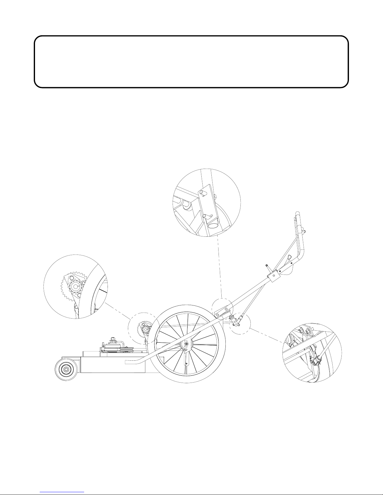
1. Install handle by flipping handle into place using the bolts located in the
handle support. See diagram a. (Note that the handle frame is slotted so the
handle can be adjusted to the right operator height for operator comfort).
Diagram A
Diagram C
2. Install wheel drive engaging rod and adjust so that the drive cogs engage
the tire. See diagram (b & c). Note that the tires should be inflated to 30
pounds.
Diagram B
Page 6
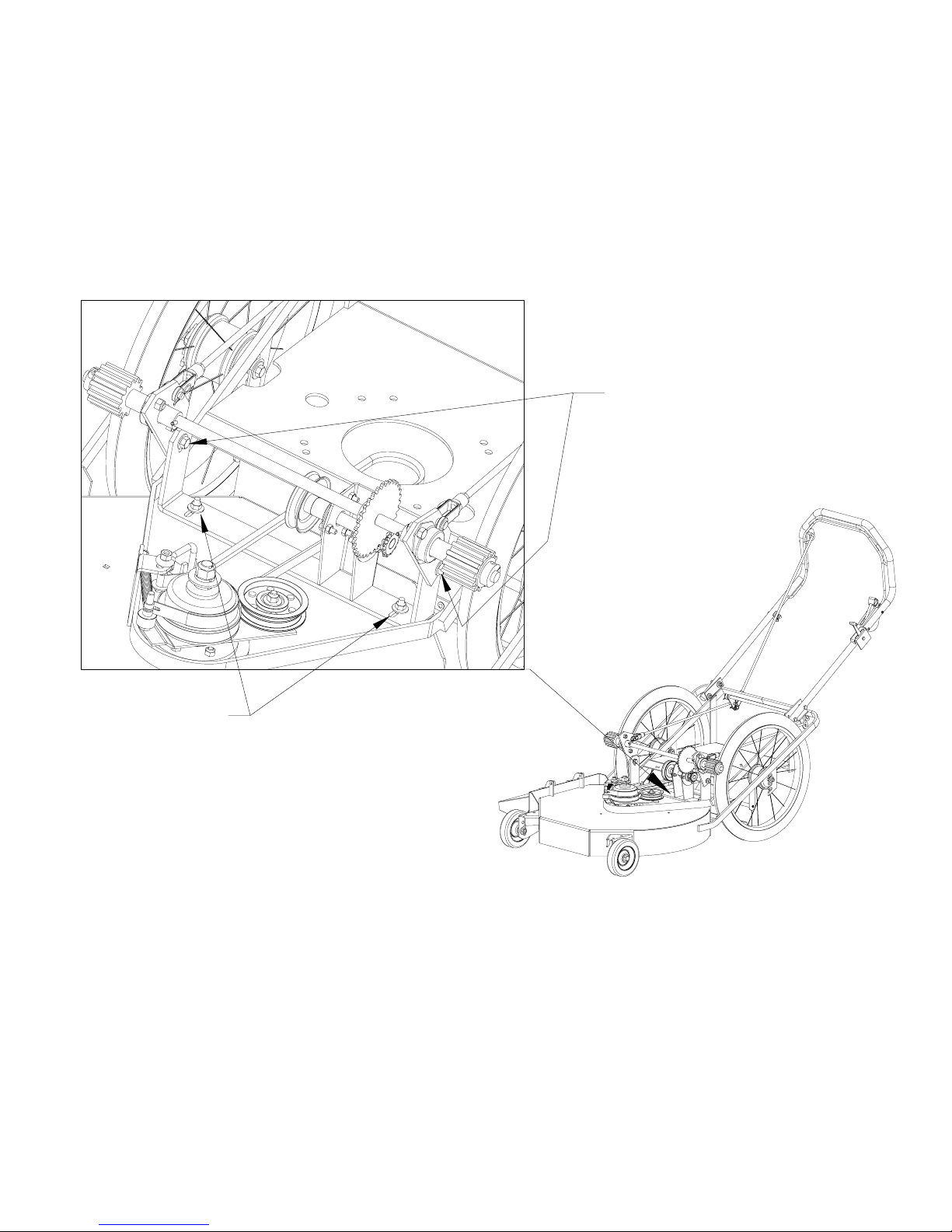
3. Drive chain may be adjusted by loosing the top bracket located by the cog
assemble (Refer to figure d) When adjusting the drive chain you must adjust
both sides equally. After adjusting the chain reset cog tension by removing the
pin in the yoke attached to the cog bracket and shortening the rod length to
increase cog pressure.
Figure D
Figure E
4. The drive belt maybe adjusted by loosening the bolts in the lower frame
support and shifting it forward of back. (Refer to f)
Page 7
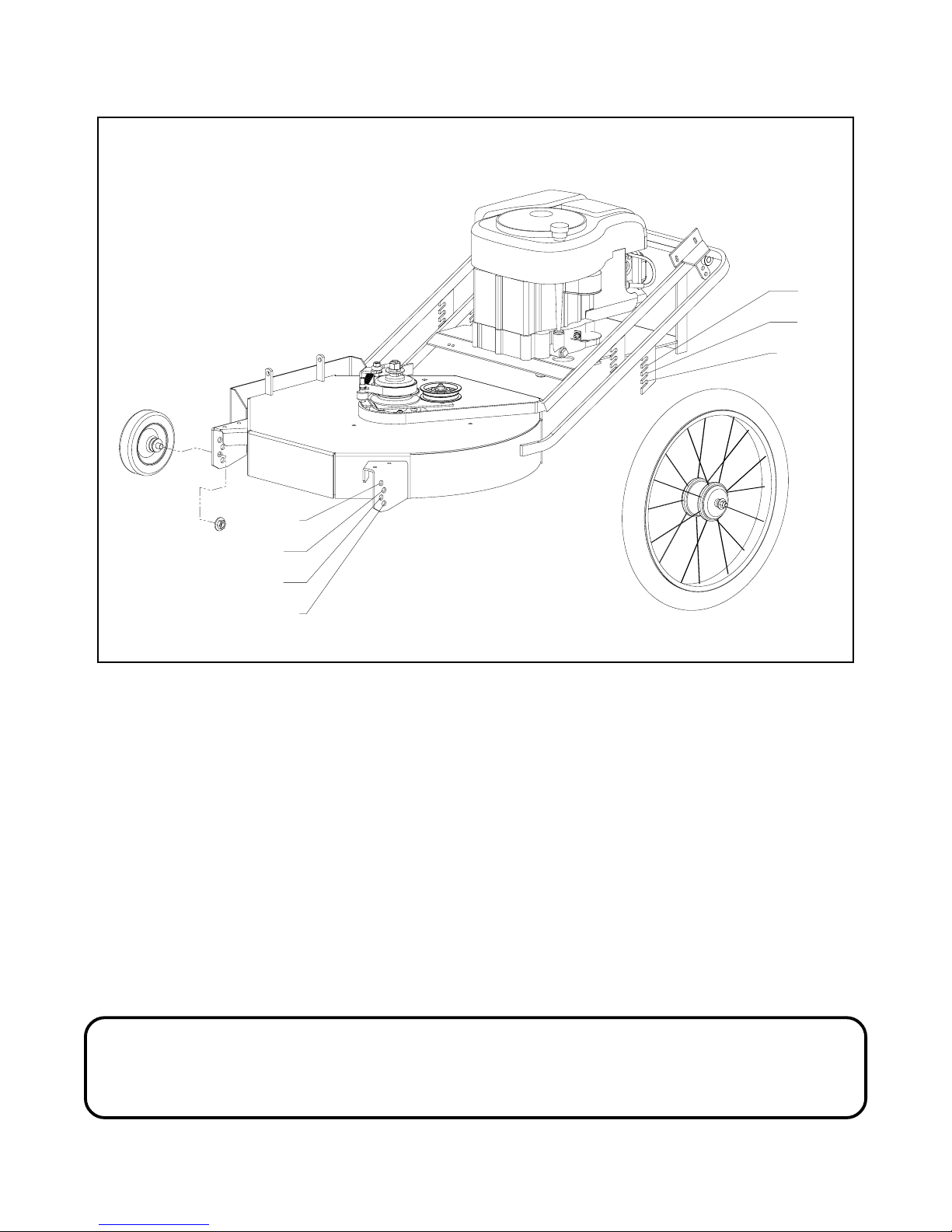
HEIGHTS ADJUSTMENTS:
CAUTION:
Stop engine and remove spark plug for safety.
1 1/2"
2"
3"
3 1/4"
2"
3"
3 1/4"
Figure C
Adjust cut setting by changing wheel heights according to figure (c).
Mower blade:
Check sharpness of mower blades after every 10 hours of operation. To sharpen
blades proceed as follows.
a. Block front of mower up.
Page 8
b. Remove blade by turning bolt counter clockwise.
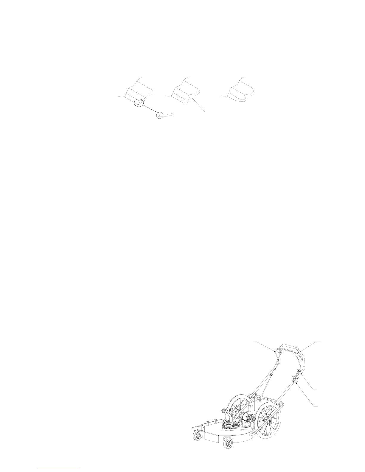
c. Blades should be discarded when worn excessively. See Sketch.
New Blade
25 Degrees
When Notch Starts
Discard Blade
Dangerous!
d. Sharpen blades with a hand file, electric grinder or blade sharpener. Wear
gloves and eye protection when sharpening. Grind blade at original bevel.
e. Check balance of blade by positioning the blade on a nail or blade balance
pedestal.
f. Reinstall blade making sure that the disc spring washer is bowl side up and re-
torque bolt to 90 ft pounds.
To Begin Operation
The throttle control/choke lever is located on left side of handlebar. To engage
choke, push throttle control lever all the way forward.
Choke as required and start engine.
With engine running, engage the brake bail by squeezing it to the handlebar.
Then push forward on the black plastic drive lever (located on left side of
handlebar just above the throttle control) until it locks into the forward position.
To drive machine forward, engage the
wheel drive bail (located on the
uppermost part of handlebar) by
squeezing it to the handlebar.
To stop machine from pulling forward,
release only the wheel drive bail.
To shut off engine: release the wheel
drive bail and the brake bail. Adjust the
throttle control to the engine stop
position.
Brake Bail Drive Bail
Drive Lever
Throttle Control
Page 9

6
5
7
8
12
13
4
3
2
1
11
1. 12 V electric starter
2. Oil dra in plug
3. F uel fill
4. Fuel tank
5. Oil fill/Dips tick
6. Finger guard
7. R ope ha ndle
8. Air cleaner
GENERAL INFORMATION
ENGINE MODEL
T his is a s ingle cylinde r, L -head, a ir-coole d e ngine. It is a
low emissions engine.
MODE L S E R IE S 280000
Bore 3-7/16 in. (87.31 mm). . . . . . . . . . . . . . . . . . . . . . . . . .
S troke 3-1/16 in. (77.78 mm). . . . . . . . . . . . . . . . . . . . . . . .
Displacement 28.42 cu. in. (465.7 cc). . . . . . . . . . . . . . . .
Note: For pra ctical opera tion, the hors e power loading s hould
not exceed 85% of rated horsepower. E ngine power will decrease 3-1/2% for each 1,000 feet (300 meters) above sea
level and 1% for each 10 F (5.6 C) above 77 F (25 C).
Engine will operate satisfactorily at an angle up to 15 .
9
10
9. E ngine Model Type Code
xxxxx xxxx xx xxxxxxxx
10. Muffler/(Muffler gua rd, if equipped)/
(S park a rres ter, if equipped)
11. S park plug wire
12 . R ota ting s cre e n
13. Blower housing
14. Fuel filter
15. Carburetor
OIL CAPACITY
E ngine Model Series 280000 holds about 1-1/2
qts (48 ozs or 1.4 ltrs).
TYPE OF OIL TO USE
Us e a high qua lity de tergent oil clas s ified “F or S ervice
SF, SG, SH, SJ” or higher, such as Briggs & Stratton
30W, P art Number 100005 (20 oz) or 100028 (48 oz).
Do not us e s pecia l additives .
Choose a viscosity according to the table opposite.
Note: Synthetic oil meeting ILSAC GF-2, API
ce rtification ma rk a nd A P I s ervice symbol
(shown at left) with “S J /C F E NE R GY C ONS E R V I N G ” or higher, is a n acce ptable oil a t all
temperatures. Us e of s ynthetic oil does not
alter required oil change intervals.
14
15
TUNE -UP S PE C IFIC ATIONS
Armature air gap 0.010 – 0.014 in. (0.25 – 0.36 mm). . .
S park plug gap 0.030 in. (0.76 mm). . . . . . . . . . . . . . . . . .
Va lve clea rance with valve s prings ins talle d a nd pis ton 1/4 in.
(6 mm) past top dead center (check when engine is cold).
S ee R epair Manual P/N 270962.
Model 280000 intake .005 – .007 in. (.13 – .18 mm). . . . .
Model 280000 exhaust .009 – .011 in. (.23 – .28 mm). . .
C AU T ION: T his engine is s hipped from B riggs &
S tratton without o il
e n gine . I f you s ta rt the e ngine withou t oil, the e ngine
will be da ma ged be yond repair a nd will not be
covered under warranty.
. C heck oil le vel before s tarting
SAE Viscosity Grades
**
*
-20 0 20 40 60 80 100
F
-30 -20 -10 0 10 20 30 40
C
STARTING TEMPERATURE RANGE ANTICIPATED BEFORE NEXT OIL CHANGE
* CAUT ION: Air cooled engines run hotter than
automotive engines. T he use of non-synthetic
multi-vis cos ity oils (5W-30 , 10W-30, e tc.) in
tempera ture s above 40 F (4 C ) will re s ult in higher
than norma l oil cons umption. W he n us ing a
multi-vis cos ity oil, check oil leve l more freque ntly.
** C A UTION: SAE 30 oil, if used below 40 F (4 C), will
res ult in hard s tarting and pos sible engine bore
damage due to inadequa te lubrication.
32
Page 10

PARTS MANUAL
SECTION
Page 11

HANDLE ASSEMBLY
16
16
1
151314
4
6
5
8
11
3
2
2
18
20
19
17
20
5
9
10
18
12
25
Page 12

26" High Wheel Walk-Behind
Handle Assembly
QTY
1
1
QTY
PART #
PART #
QTY
PART #
# QTY
1
12
22
31
41
53
61
71
81
91
10 1
11 1
12 1
13 1
14 1
15 1
16 2
17 1
18 4
19 7
20 4
DESCRIPTION
HANDLE ASSY.
DESCRIPTION
100258
101298
103003
103021
104255
105259
105507
262006
263036
263058
263062
263088
263089
363165
363196
FINAL ASSY
100295 3/8-16 X 1-3/4 HHCS
104257 3/8 – 16 NYLOC NUT
105260 3/8 STD FLAT WASHER
1/4 - 20 X 2.00 HHCS
# 10 – 24 x 2 1/4
#10-14 x 1/2 PLASTITE SCREW (FOR PLASTIC)
ROPE GUIDE
1/4 - 20 NYLOC NUT
3/8 SAE FLAT WASHER
POP RIVET BURR 3/16
DRIVE BAIL WELDMENT
DRIVE CABLE
HANDLE
BRAKE BAIL
BAIL PUSH NUT
THROTTLE CONTROL
ENGAGEMENT ROD ASSY.
PART # DESCRIPTION
104754 3/8 – 24 HEX JAM NUT
263066 DRIVE ENGAGEMENT ROD
363192 LARGE YOKE
# 3 HAIRPIN
CLEVIS PIN – 3/8
DESCRIPTION
Page 13

MOWER DECK ASSEMBLY
5
7
17
31
29
32
32
30
13
16
44
41
40
11
3
22
37
38
34
39
32
1
15
35
38
43
42
20
38
33
3
18
14
24
26
27
25
26
26
9
25
12
2
19
5
9
25
27
24
26
10
21
Page 14

26" High Wheel Walk-Behind
Mower Deck Assembly
# QTY
11
210
311
47
52
62
71
84
94
10 1
11 1
12 1
13 3
14 1
15 1
16 1
17 1
18 1
19 1
20 1
21 1
22 1
23 2
24 1
25 1
26 2
27 1
28 1
29 1
30 1
31 1
32 2
33 1
34 1
35 2
PART # DESCRIPTION
QTY
1
PART # DESCRIPTION
100273 5/16 – 18 X 1 HHCS
104256 5/16 – 18 NYLOC NUT
104257 3/8 – 16 NYLOC NUT
104512 5/8 – 18 HEX NUT
104755 1/2 - 20 HEX JAM NUT PLATED
105009 LOCKWASHER - .625
105260 3/8 STD FLAT WASHER
105264 1/2 STD. FLATWASHER
107009 WOODRUFF KEY
107266 3/16 X 3/16 X 2 MACHINE KEY
107503 5/16 – 18 x 3/4 CARRIAGE HEAD BOLT
109007 3/8 - 16 WHIZLOCK NUT
263008 BLADE SPINDLE PULLEY
263012 SPACER - BLADE SHAFT
263016 BLADE BRAKE HUB
263072 BRAKE CONDUIT HOLDER
263092 26” BLADE
263097 RETAINING RING
263098 BLADE DRIVER
263115 BLADE BRAKE - GUIDE
QTY
QTY
AR
QTY
DEFLECTOR SHIELD
FINAL ASSY
MAIN FRAME WELDMENT – PAINTED
FRONT WHEEL ASSY.
PART # DESCRIPTION
100537 1/2 - 20 x 2 1/2 HHCS UNF
104755 1/2 - 20 HEX JAM NUT
105264 1/2 STD. FLATWASHER
263087 FRONT WHEEL
SPINDLE HOUSING ASSY
PART # DESCRIPTION
262018 SPINDLE HOUSING WELDMENT
263023 BLADE SPINDLE
263097 RETAINING RING
553011 SPINDLE BEARINGS
THREAD LOCKER 242
BLADE BRAKE ARM ASSY
PART # DESCRIPTION
100295 3/8 – 16 X 1.75 HHCS
100296 3/8 – 16 x 2.0 HHCS
104257 3/8 – 16 NYLOC NUT
Page 15

26" High Wheel Walk-Behind
Mower Deck Assembly
# QTY
36 1
37 1
38 3
39 1
40 1
41 1
42 1
43 1
44 1
PART # DESCRIPTION
QTY
PART # DESCRIPTION
104753 3/8 – 16 JAM NUT
105259 3/8 SAE WASHER
105260 3/8 STD WASHER
262012 BLADE BRAKE WELDMENT
263028 BRAKE BAND
263076 BRAKE SPRING
363097 SPACER - TURNBUCKEL
523328 FLAT IDLER – MULE DRIVE
823309 FRAME SPACER – pltd.
Page 16

DRIVE ASSEMBLY
5
34
32
23
31
32
24
25
27
22
20
12
14
35
4
6
34
11
16
8
9
26
23
31
35
15
18
8
30
29
9
33
9
7
28
9
22
9
33
11
13
29
9
19
17
19
21
32
30
20
22
32
5
12
3
10
2
1
Page 17

26" High Wheel Walk-Behind
Drive Assembly
# QTY
12
21
31
41
51
61
72
82
96
10 1
11
12 2
13
14
15
16
17
18
19
20
21
22
23
24
25
26
27
28
29
30
PART # DESCRIPTION
FINAL ASSY
QTY
2
1
PART # DESCRIPTION
107509 5/16-18 X 1 CARR. BOLT
263050 BELT SHIELD
263063 DRIVE BELT
264012 DRIVE ROD ASSY
QTY
QTY
1
1
1
PART # DESCRIPTION
104754 3/8 – 24 HEX JAM NUT
263034 DRIVE ROD
363192 LARGE YOKE
FINAL DRIVE ASSY.
PART # DESCRIPTION
100293 3/8-16 X 1-1/4 HHCS
104257 3/8-16 NYLOC NUT
105258 5/16 STD. FLATWASHER
263090 DRIVE CHAIN
263091 CONN. LINK
QTY DESCRIPTION
6 1/4 -20 x 3/4 HHCS
6 1/4 - 20 NYLOC NUT
1 JACK SHAFT WELDMENT
1 CONVERSION PULLEY
1 MED. SPROCKET
1 17mm JACK SHAFT
1 BEARING SPACER
2 3 BOLT 17mm BEARING
QTY DESCRIPTION
4 3/8 – 16 X 3/4 HHCS
2 5/16 – 18 X 3/8 SET SCREW
4 3/8 – 16 NYLOC NUT
4 5/8 SAE WASHER
2 3/16 x 1.50 ROLLPIN
1 DRIVER w/ BEARING RIGHT
1 DRIVER w/ BEARING LEFT
1 DRIVE SHAFT
1 LARGE SPROCKET
2 DRIVE SHAFT SUPPORT
QTY DESCRIPTION
2 FLANGE BEARING
PART #
PART #
PART #
JACKSHAFT ASSY
100252
103293
104255
262010
263020
263056
263109
263111
263112
DRIVE ASSY
100291
103293
104257
105267
106328
262021
262022
263018
263024
263026
363292
SETSCREWS - KNURLED CUP
POINT
Page 18

26" High Wheel Walk-Behind
Drive Assembly
# QTY
31
32
33 2
34 4
35 2
PART # DESCRIPTION
QTY DESCRIPTION
2 5/8 CLAMP COLLAR
4 BLADE SPACER
363174 EYEBOLT SPACER
363165 COTTER PIN # 2 HAIRPIN
363196 CLEVIS PIN –3/8
PART #
363339
373086
Page 19

HEIGHT ADJUSTMENT ASSEMBLY
16
16
20
4
16
18
7
19
13
3
1
11
9
10 12
5
6
1
3
11
8
3
13
2
21
15
9
22
14
Page 20

26" High Wheel Walk-Behind
Height Adjustment Assembly
# QTY
12
27
34
41
51
61
71
82
94
10 1
11 2
12 1
13 2
14 2
15 2
16 2
17 4
18 1
19 1
20 1
21 2
22 4
PART # DESCRIPTION
QTY
1
1
PART # DESCRIPTION
QTY
QTY
FINAL ASSY
100306 3/8 – 16 x 5 HHCS
104257 3/8 – 16 NYLOC NUT
105260 3/8 STD FLAT WASHER
105266 1/2 SAE FLAT WASHER
106763 1/8 x 11/4 COTTER PIN
262008 DRIVE CRANK WELDMENT
263064 DECK DRIVE BELT
263086 DRIVE WHEELS
263117 DRIVE WHEEL SPACER
DRAG FLAP ASSY
PART # DESCRIPTION
262023 DRAG FLAP w/ STIFFENERS
263014 DRAG SHIELD STRAP
263075 DRAG FLAP ROD
363219 PUSH NUT
8.5 HP BRIGGS ENGINE ASSY.
PART # DESCRIPTION
100275 5/16 – 18 X 1 1/2 HHCS
100276 5/16 – 18 X 1 3/4 HHCS
103293 SET SCREWS 5/16 – 18 X 3/8
104256 5/16 – 18 NYLOC NUT
107259 .25 X .25 X 1.00 MACH. KEY
263085 ENGINE PULLEY
SEE NOTE 8.5 HP BRIGGS W/FUEL TANK
363075 BELT GUIDE
363226 DISC SPRING
NOTE:
ENCORE MFG. CO. DO NOT SERVICE OR STOCK PARTS FOR ENGINES ON OUR UNITS.
PLEASE CONTACT ENGINE MFG. FOR PART INFORMATION.
Page 21

DECAL LIST
Page 22

26" High Wheel Walk-Behind
Decal List
# QTY
11
21
31
41
52
61
71
81
91
PART # DESCRIPTION
263031 CLASSIC LABEL
263069 PRO 26 LABEL
263118 WHEEL DRIVE DECAL
363001
363023
363026
363317
363318 POLY ENCORE LOGO
823323 ROTATING PARTS DECAL
CAUTION DECAL
DANGER DECAL
SERIAL NO. PLATE
POLY ENCORE LABEL
Page 23

ENCORE WARRANTY
This warranty extends to the original retail purchaser only and commences on the date of
original retail purchase. Any part of the Encore commercial mower manufactured by Encore
Mfg. Co., Inc. and found in reasonable judgment of Encore Mfg. Co., Inc. to be defective in
material or workmanship, will be repaired or replaced by an authorized Encore Dealer without
charge for parts and labor. The Encore mower including any defective part must be returned to
an authorized Encore service dealer within the warranty period. The expense of delivering the
mower to the dealer for warranty work and the expense of returning it back to the owner after
repair or replacement will be paid by the owner. Should any part prove to be defective within
the two years (tires, belts and batteries are 90 days) of original purchase (90 days for rental
purposes), the part will be replaced F.O.B. Beatrice, Nebraska.
Cutter housings, electrical components, hydraulic components and electric clutch must be
returned before warranty will be paid.
The responsibility of Encore Mfg. Inc. In respect to claim is limited to making the required
repairs or replacements, and no claim of breach of warranty shall be cause for cancellation or
recession of the contract of sale of any Encore mower.
Proof of purchase is required by both Encore and servicing Dealer before any warranty will be
paid, and warranty work must be preformed by an authorized Encore service dealer.
This warranty does not cover any Encore mower that has been altered or modified so as to
adversely affect the intended use of the product, it operation, performance, or durability. As will
as any mower that has been subject to misuse, neglect, negligence, accident or that has been
operated in any way contrary to the operating instructions as specified in the Operators
Manual.
This warranty does not cover the engine, which is warranted separately by the engine
manufacturer. However this warranty covers the Peerless 5 Speed Transmission for a period of
one year.
Encore Mfg. Co., Inc. reserves the right to change or improve the design of any mower without
assuming any obligation of any mower without assuming any obligation to modify any mower
previously manufactured.
Encore Mfg. Co., Inc. obligation under warranty is strictly and excessively limited to repair or
replacement of defective parts. Encore Mfg. Co., Inc. does not assume or authorize anyone to
assume for them any other obligation.
ENCORE MFG. CO., INC. CANNOT BE RESPONSIBLE FOR THE WAY YOU
OPERATE, OR THE CONDITIONS IN WHICH YOU OPERATE THE MOWER.
USE COMMON SENSE AT ALL TIMES.
Page 24

0802 A
All rights reserved. Contents subject to change. Part Number
,ENCORE MANUFACTURING CO., INC.
26SP100 - OPERATORS/PARTS MANUAL
CLASSIC
933113
 Loading...