

Page 1

Encore
BSD – 4
Blind Spot Detection System
Part of the Encore ADAS System
(Advanced Driver Assistance System)
For professional installation only
Installation manual
Precautions:
This device is a driving aid and in no way will replaces safe driving habits. Proper use of your mirrors and looking over
your shoulder when changing lanes is always emphasized. Though this devise is state of the art, it should not solely
be relied upon during safe operation of a motor vehicle. The BSD-4 is an accessory that can help the driver change
lanes safely and aid in blind spot detection. Encore Automotive Systems and the installing dealer are not liable for
any and all damages as a result of using this product. Always use safe driving habits regardless of the assistive systems
in use.
Prior to Installation:
It is highly recommended that this unit be connected on a bench prior to installing it on the vehicle. This will confirm
correct function of all of the components of the system and will allow you to familiarize yourself with its wiring and
functions. The front sensors of the BSD-4 are not actively used like the rear sensors. These front sensors are only used
by the controller to help eliminate false detection. When testing on a bench it is recommended that the unit is switched
to enhanced mode to verify the units operation. This will turn OFF the front sensors making it easier to test. Once
testing has been completed, please switch the unit back to Normal mode for operation. If left in enhanced mode, the
unit will give false signals for stationary objects that could be along the side of the road.
NOTE: The front sensors will not aluminate the LED indicators or cause the Buzzer to sound.
Sensor installation:
The BSD-4 comes with 4 sensors and a large vehicle wiring harness with all connectors in place. These connectors are
clearly marked and thought should be given to the routing of these wires. The rear sensors are used for the detection of
vehicles that are in the blind spot of the vehicle. The front sensors will not activate a warning and they are only used in
the logic circuit to eliminate false readings.
Concept: When driving close to a wall of other stationary object, both the front and rear sensors will see the object.
When this happens, the logic controller knows that the object is in fact stationary and will not indicate an alert. Failure
to install these front sensors will make the system unreliable and will cause excessive false readings.
Page 2
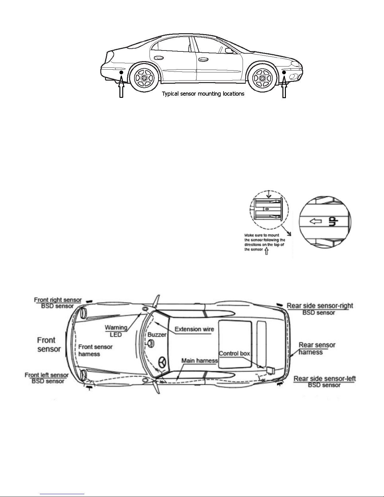
The 4 sensor should be installed in the front and rear quarter panels of the vehicle. They should be installed at a
minimum height above the ground of 18” and a maximum height of 28”. These sensors have a small arrow and the
word “up” and should always be installed with the up arrow facing UP. A hole saw included with this kit will cut the
correct size hole for the sensors. Please mark the desired installation location for these sensors and verify that you will
have access to the wires prior to drilling in any vehicle. Once the location has been finalized and access to the wires has
been confirmed, use the hole saw provided to drill the correct hole size for the sensors. Once drilled, please remove all
excess material and make sure that the hole is cleared of any burs or debris. Install the sensors with the UP indicator
facing UP and run the wires through the holes.
Carefully plan where the sensors will be mounted before drilling.
Insure that there is room to reach the sensor wires.
Drill the sensor holes with the supplies hole saw.
Clear the holes of all debris.
Insert the sensor with the arrow and up indicator facing UP.
Sensor and Component Locations:
Please insure that the wire harness is secure and away from all objects that may cut the protective coating. The wire
harness is clearly marked with Tags to insure a correct connection. Please insure these connections are completed
before applying power to the unit.
Page 3

Function
ON ( Default )
Normal operation
OFF
Unit is OFF
Response
NORMAL ( Default )
Front Sensors limit false alarms
Enhanced , NOT RECOMMENDED
No Limiting Logic and will trigger often
Active Mode
Always ( Default )
Always ON
Only Turning
ON Only when Turning
Sensitivity
Normal ( Default )
Sensor Range 10 ft. Length and 10 Ft. Width
Low
Reduced Sensor Range
Buzzer Adjustment:
The Buzzer volume can be adjusted by the
three way switch on the buzzer.
Parts List:
Encore Main Controller (1)
BSD-4 Sensors (4)
Adjustable Buzzer (1)
Warning Pillar Mount LED’s (2)
Main Wire Harness (1)
Front Sensor Harness (1)
Rear Sensor Harness (1)
Right Side LED Extension Harness (1)
Installation Kit (1)
Controller settings:
Because of the custom harness the controller should be mounted in the left side of the trunk area. Please
properly secure the controller and make sure it does not interfere with any moving parts in that area. The
controller is Factory preset with standard options but has several adjustments that can be made if needed for
specific applications. These are set by 4 dip switches at the right of the controller harness at the controller
itself.
Page 4

System Wiring:
Wire Description:
Black: Connect this wire to a stable chassis ground. (-)
Red: Connect this wire to 12 V + Ignition. This wire should be ON while the vehicle is in operation.
Green: Connect this wire to the Positive Left turn indicator wire. (+) when left turn indicator is activated.
Yellow: Connect this wire to the positive Right turn indicator wire. (+) when Right turn indicator is activated.
White: Connect this wire to the positive reverse light wire connection. (+) when in reverse.
Mounting the LED Indicators:
The LED Indicators should be mounted within the vehicle and as close to the side mirrors as possible. They have pre-
installed backings that can be affixed to any smooth surface. The kit also contains two metal mounting points that can
be used to mount the indicator between panels or molding should you chose to do so. Please insure that the wires for
the sensor are hidden and out of the customer’s sight. A hole can be drilled for the wires in certain custom installations.
If a hole is used, please be sure the connector will fit through the hole and is kept intact.
Testing and operation:
When the installation has been completed, the unit should be tested before delivery to the customer. Please do this in
an open area with the ignition in the ON position.
The unit should light the LED indicator when someone or something is within range of the rear sensors. When on the
right side the right indicator should light up and the same with the left. The unit will not trigger if there is anything in
the range of either of the front sensors. They are used to sense stationary object such as wall on a street or freeway and
will stop the rear sensors from triggering next to stationary object or moving objects that can be easily seen by the
driver.
Page 5

When the right or left turn indicator is ON and an object is seen by the rear sensor ONLY on that side the buzzer will
start to signal with a Bi..Bi.. Sound. This sound level can be adjusted at switch on the buzzer.
FAQ:
The unit does not respond at all. Please check the power and ground connections and insure that the inline
fuse is not damaged or blown.
The LED Indicators do not work correctly. Please insure that the sensors are plugged in to the correct points of
the harness. Please also make sure there is nothing that could cause the front sensors to activate.
Bring the vehicle to an open area and retest the install.
The sensors false or do not react to objects. Please ensure that the sensors are installed with the UP arrow
facing upward. Also insure that the sensors are not in contact with any metal part of the vehicles frame and are
clear of debris.
The front sensors do not activate the warning lights or buzzer. This is correct operation. The front sensors are
used to defeat false reading when in close contact to walls, railings or parked vehicles.
The buzzer only works when the turn indicators are on. This is correct operation. The lights should activate
when a vehicle is in the blind spot and detected. The buzzer will only operate when the turn indicator is applied
in that direction.
Can the sensors be painted? Yes, however a light coat is recommended for best sensing results.
The unit is too sensitive. By default the system is set at normal sensitivity giving maximum detection range.
This can be set to a lower setting
The unit gives false readings. Please insure that the response switch is set to the normal setting.
This product is covered by a one year manufacturer’s warranty that covers all manufacturing defects of this
product. This warranty does not cover abuse or installation related problems that may occur. Proof of purchase
and installation by a certified Encore dealer will be needed for all warranty claims.
This device is a driving aid and in no way will replaces safe driving habits. Proper use of your mirrors and looking over
your shoulder when changing lanes is always emphasized. Though this devise is state of the art, it should not solely
be relied upon during safe operation of a motor vehicle. The BSD-4 is an accessory that can help the driver change
lanes safely and aid in blind spot detection. Encore Automotive Systems and the installing dealer are not liable for
any and all damages as a result of using this product. Always use safe driving habits regardless of the assistive systems
in use.
For Dealer Tech Support please call 855-463-6267: Ext 3
Customerservice@encoreautomotivesystems.com
Encore
Automotive Systems
27240 Turnberry Lane Suite 200, Valencia CA 91355
(855) 463-6267
 Loading...