

Page 1

EncorerMobile Powder Spray
System with Feed Hopper
Customer Product Manual
Part 1102771A
Issued 6/10
For parts and technical support, call the
Finishing Customer Support Center at (800) 433-9319.
This document is subject to change without notice.
Check http://emanuals.nordson.com/finishing for the latest version.
NORDSON CORPORATION AMHERST, OHIO USA
C
APPROVED
FM
US
Page 2

Contact Us
Nordson Corporation welcomes requests for information, comments, and
inquiries about its products. General information about Nordson can be
found on the Internet using the following address:
http://www.nordson.com.
Address all correspondence to:
Nordson Corporation
Attn: Customer Service
555 Jackson Street
Amherst, OH 44001
Notice
This is a Nordson Corporation publication which is protected by copyright.
Original copyright date 2009. No part of this document may be
photocopied, reproduced, or translated to another language without the
prior written consent of Nordson Corporation. The information contained
in this publication is subject to change without notice.
Trademarks
Encore, iFlow, Nordson, and the Nordson logo are registered trademarks
of Nordson Corporation.
Part 1102771A
E 2010 Nordson Corporation
Page 3

Table of Contents i
Table of Contents
Safety 1-1..................................................
Introduction 1-1.............................................
Qualified Personnel 1-1......................................
Intended Use 1-1...........................................
Regulations and Approvals 1-1...............................
Personal Safety 1-2.........................................
Fire Safety 1-2.............................................
Grounding 1-3..............................................
Action in the Event of a Malfunction 1-3........................
Disposal 1-3...............................................
System Setup 2-1..........................................
Introduction 2-1.............................................
Specifications 2-2........................................
Applicator Certification Label 2-2.........................
Power Unit and Gun Interface Controllers
Certification Label 2-2..................................
System Connections 2-3.....................................
System Diagram 2-3......................................
Controller Connections 2-3................................
Hopper Installation 2-5......................................
Pump Installation 2-6........................................
Pump Mounting 2-6.......................................
Pump Connections 2-7....................................
Spray Gun Connections 2-8..................................
Gun Cable 2-8...........................................
Spray Gun Air Tubing Connections 2-9......................
Spray Gun Powder Tubing Connection 2-10...................
Bundling Tubing and Cable 2-10.............................
System Air and Electrical Connections 2-11.....................
System Air Supply 2-11....................................
Electrical Connections 2-12.................................
System Ground 2-12.......................................
E 2010 Nordson Corporation
Part 1102771A
Page 4

ii
Table of Contents
Operation 3-1..............................................
European Union, ATEX, Special Conditions for Safe Use 3-1.....
Daily Operation 3-1.........................................
Startup 3-1..............................................
Factory Set Presets 3-2...................................
Spray Gun Operation 3-3..................................
Changing Presets with the Settings Trigger 3-3.............
Changing Powder Flow with the Settings Trigger 3-3........
Purging the Gun 3-3....................................
Standby Button 3-4.......................................
Electrode Air Wash Operation 3-4..........................
Changing Flat Spray Nozzles 3-4...........................
Changing Deflectors or Conical Nozzles 3-5..................
Installing the Optional Pattern Adjuster Kit 3-6................
Shutdown 3-6...............................................
Maintenance 3-7............................................
Using the Controller Interface 3-8.............................
Help Codes 3-9.............................................
Maintenance Timer, Configuration, and Versions 3-9.............
Preset Setup 3-10...........................................
Selecting Presets 3-10.....................................
Electrostatic Settings 3-10....................................
Select Charger Mode 3-10..................................
Custom Mode 3-11........................................
Classic Mode 3-11.........................................
Classic Standard (STD) Mode 3-11........................
Classic AFC Mode 3-12..................................
Powder Flow Settings 3-13....................................
Smart Flow Mode Settings 3-13.............................
Setting Smart Flow Setpoints 3-14.........................
Smart Flow Settings -- Metric Units 3-15....................
Smart Flow Settings -- English Units 3-16...................
Classic Flow Mode Settings 3-17............................
Controller Configuration 3-17..................................
Opening the Function Menu and Making Settings 3-17.........
Vibratory Box Feeder On Continuously 3-18...................
Saving and Loading Preset and Function Settings 3-19.........
Setting the Number of Presets 3-19..........................
Part 1102771A
Troubleshooting 4-1........................................
Help Code Troubleshooting 4-1...............................
Viewing Help Codes 4-1...................................
Clearing Help Codes 4-1..................................
Help Code Troubleshooting Chart 4-2.......................
General Troubleshooting Chart 4-5............................
Re-Zero Procedure 4-9....................................
Spray Gun Power Supply Resistance Test 4-10..................
Electrode Assembly Resistance Test 4-10.......................
Gun Cable Continuity Test 4-1 1................................
Controller Interconnect Cable Test 4-11.........................
System Wiring Diagrams 4-12.................................
E 2010 Nordson Corporation
Page 5

Table of Contents iii
Repair 5-1.................................................
Spray Gun Repair 5-1.......................................
Display Module Replacement 5-1...........................
Display Module Removal 5-1............................
Display Module Installation 5-1...........................
Power Supply Replacement 5-3............................
Power Supply Removal 5-3..............................
Power Supply Installation 5-3............................
Trigger Switch, Gun Cable, and Handle Replacement 5-4......
Gun Disassembly 5-5...................................
Gun Re-assembly 5-8..................................
Interface Module Repair 5-12..................................
Power Unit Repair 5-13.......................................
Removing the Sub Panel 5-13..............................
Sub Panel Components 5-14................................
Regulator Replacement 5-14................................
iFlow Module Repair 5-15...................................
Testing iFlow Modules 5-15...............................
Flow to Pressure Chart 5-17..............................
Solenoid Valve Replacement 5-17.........................
Proportional V alve Cleaning 5-17..........................
Proportional V alve Replacement 5-19......................
Parts 6-1...................................................
Introduction 6-1.............................................
System Part Numbers 6-1...................................
Spray Gun Parts 6-2........................................
Spray Gun Options 6-5......................................
Miscellaneous Spray Gun Options 6-5.......................
Flat Spray Nozzles 6-5....................................
Conical Nozzle and Deflectors 6-6..........................
Optional Cross Cut Nozzles 6-6............................
Optional Pattern Adjuster Kit 6-7...........................
Controller Parts 6-8.........................................
Interface Parts Exploded View 6-8..........................
Interface Parts List 6-9....................................
Power Unit Parts Exploded View 6-10........................
Power Unit Parts List 6-11..................................
iFlow Module Parts 6-12....................................
System Components and Parts 6-13...........................
Powder Hose and Air Tubing 6-13...........................
Options 6-14..............................................
Pump Parts 6-14..........................................
Pump Adapter Kit 6-14.....................................
E 2010 Nordson Corporation
Part 1102771A
Page 6

iv
Table of Contents
Part 1102771A
E 2010 Nordson Corporation
Page 7

Introduction
Safety
Section 1
Safety
Read and follow these safety instructions. Task- and equipment-specific
warnings, cautions, and instructions are included in equipment
documentation where appropriate.
Make sure all equipment documentation, including these instructions, is
accessible to all persons operating or servicing equipment.
1-1
Qualified Personnel
Equipment owners are responsible for making sure that Nordson equipment
is installed, operated, and serviced by qualified personnel. Qualified
personnel are those employees or contractors who are trained to safely
perform their assigned tasks. They are familiar with all relevant safety rules
and regulations and are physically capable of performing their assigned
tasks.
Intended U se
Use of Nordson equipment in ways other than those described in the
documentation supplied with the equipment may result in injury to persons
or damage to property.
Some examples of unintended use of equipment include
S using incompatible materials
S making unauthorized modifications
S removing or bypassing safety guards or interlocks
S using incompatible or damaged parts
S using unapproved auxiliary equipment
S operating equipment in excess of maximum ratings
Regulations and A pprovals
E 2010 Nordson Corporation
Make sure all equipment is rated and approved for the environment in which
it is used. Any approvals obtained for Nordson equipment will be voided if
instructions for installation, operation, and service are not followed.
All phases of equipment installation must comply with all federal, state, and
local codes.
Part 1102771A
Page 8

1-2
Safety
Personal Safety
To prevent injury follow these instructions.
S Do not operate or service equipment unless you are qualified.
S Do not operate equipment unless safety guards, doors, or covers are
intact and automatic interlocks are operating properly. Do not bypass or
disarm any safety devices.
S Keep clear of moving equipment. Before adjusting or servicing any
moving equipment, shut off the power supply and wait until the
equipment comes to a complete stop. Lock out power and secure the
equipment to prevent unexpected movement.
S Relieve (bleed off) hydraulic and pneumatic pressure before adjusting or
servicing pressurized systems or components. Disconnect, lock out,
and tag switches before servicing electrical equipment.
S Obtain and read Material Safety Data Sheets (MSDS) for all materials
used. Follow the manufacturer’s instructions for safe handling and use
of materials, and use recommended personal protection devices.
S To prevent injury, be aware of less-obvious dangers in the workplace
that often cannot be completely eliminated, such as hot surfaces, sharp
edges, energized electrical circuits, and moving parts that cannot be
enclosed or otherwise guarded for practical reasons.
Fire Safety
To avoid a fire or explosion, follow these instructions.
S Do not smoke, weld, grind, or use open flames where flammable
materials are being used or stored.
S Provide adequate ventilation to prevent dangerous concentrations of
volatile materials or vapors. Refer to local codes or your material MSDS
for guidance.
S Do not disconnect live electrical circuits while working with flammable
materials. Shut off power at a disconnect switch first to prevent
sparking.
S Know where emergency stop buttons, shutoff valves, and fire
extinguishers are located. If a fire starts in a spray booth, immediately
shut off the spray system and exhaust fans.
S Clean, maintain, test, and repair equipment according to the instructions
in your equipment documentation.
S Use only replacement parts that are designed for use with original
equipment. Contact your Nordson representative for parts information
and advice.
Part 1102771A
E 2010 Nordson Corporation
Page 9

Grounding
Safety
WARNING: Operating faulty electrostatic equipment is hazardous and can
cause electrocution, fire, or explosion. Make resistance checks part of your
periodic maintenance program. If you receive even a slight electrical shock
or notice static sparking or arcing, shut down all electrical or electrostatic
equipment immediately. Do not restart the equipment until the problem has
been identified and corrected.
Grounding inside and around the booth openings must comply with NFPA
requirements for Class II, Division 1 or 2 Hazardous Locations. Refer to
NFPA 33, NFPA 70 (NEC articles 500, 502, and 516), and NFPA 77, latest
conditions.
1-3
S All electrically conductive objects in the spray areas shall be electrically
connected to ground with a resistance of not more than 1 megohm as
measured with an instrument that applies at least 500 volts to the circuit
being evaluated.
S Equipment to be grounded includes, but is not limited to, the floor of the
spray area, operator platforms, hoppers, photoeye supports, and
blow-off nozzles. Personnel working in the spray area must be
grounded.
S There is a possible ignition potential from the charged human body.
Personnel standing on a painted surface, such as an operator platform,
or wearing non-conductive shoes, are not grounded. Personnel must
wear shoes with conductive soles or use a ground strap to maintain a
connection to ground when working with or around electrostatic
equipment.
S Operators must maintain skin-to-handle contact between their hand and
the gun handle to prevent shocks while operating manual electrostatic
spray guns. If gloves must be worn, cut away the palm or fingers, wear
electrically conductive gloves, or wear a grounding strap connected to
the gun handle or other true earth ground.
S Shut off electrostatic power supplies and ground gun electrodes before
making adjustments or cleaning powder spray guns.
S Connect all disconnected equipment, ground cables, and wires after
servicing equipment.
Action in the Event of a Malfunction
Disposal
E 2010 Nordson Corporation
If a system or any equipment in a system malfunctions, shut off the system
immediately and perform the following steps:
S Disconnect and lock out electrical power. C lose pneumatic shutoff
valves and relieve pressures.
S Identify the reason for the malfunction and correct it before restarting the
equipment.
Dispose of equipment and materials used in operation and servicing
according to local codes.
Part 1102771A
Page 10

1-4
Safety
Part 1102771A
E 2010 Nordson Corporation
Page 11
Introduction
System Setup
2-1
Section 2
System Setup
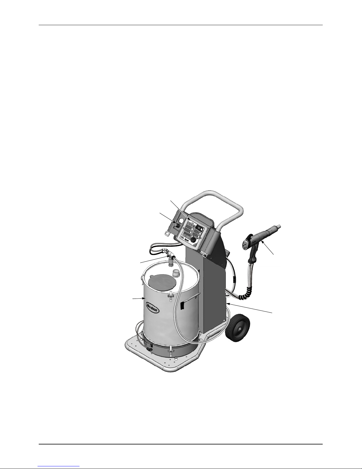
See Figure 2-1. The Encore Mobile Powder Spray System is a complete
manual powder spray system mounted on a sturdy four-wheel cart. The
system includes a manual spray gun, two-piece controller, powder pump
and pick-up tube, 25- or 50-lb (11.3- or 22.7-kg) powder feed hopper, and all
powder and air tubing required for operation.
Follow the procedures in this section to prepare the system for operation.
6
5
1
4
2
3
E 2010 Nordson Corporation
Figure 2-1 Encore Mobile Powder Spray System with Powder Feed Hopper
1. Encore spray gun
2. Powder feed hopper
3. Cart tower
Note: Power unit portion of controller is installed in rear of cart tower.
4. Encore powder feed pump
5. Fluidizing air regulator
6. Spray gun controller
Part 1102771A
Page 12
2-2
System Setup
Specifications
Model Input Rating Output Rating
ENCORE Applicator +/-- 19 VAC, 1 A 100 KV, 100 A
ENCORE Interface Control Unit 24 VDC, 2.75 A +/-- 19 VAC, 1A
ENCORE Controller Power Unit 100--240 VAC, 50/60 Hz, 85 VA 24 VDC, 2.75 A
S Input Air: 6.0--7.6 bar (87--110 psi), <5 particulates, dew point <10 _C
(50 _F)
S Max Relative Humidity: 95% non-Condensing
S Ambient Temperature Rating (Encore System): +15 to +40 _C
(59--104 _F)
S Hazardous Location Rating for Applicator: Zone 21 or Class II, Division 1
S Hazardous Location Rating for Controls: Zone 22 or Class II, Division 2
S Dust Ingress Protection: IP6X
S Hopper Capacity: 11.3 or 22.7 kg (25 or 50 lb)
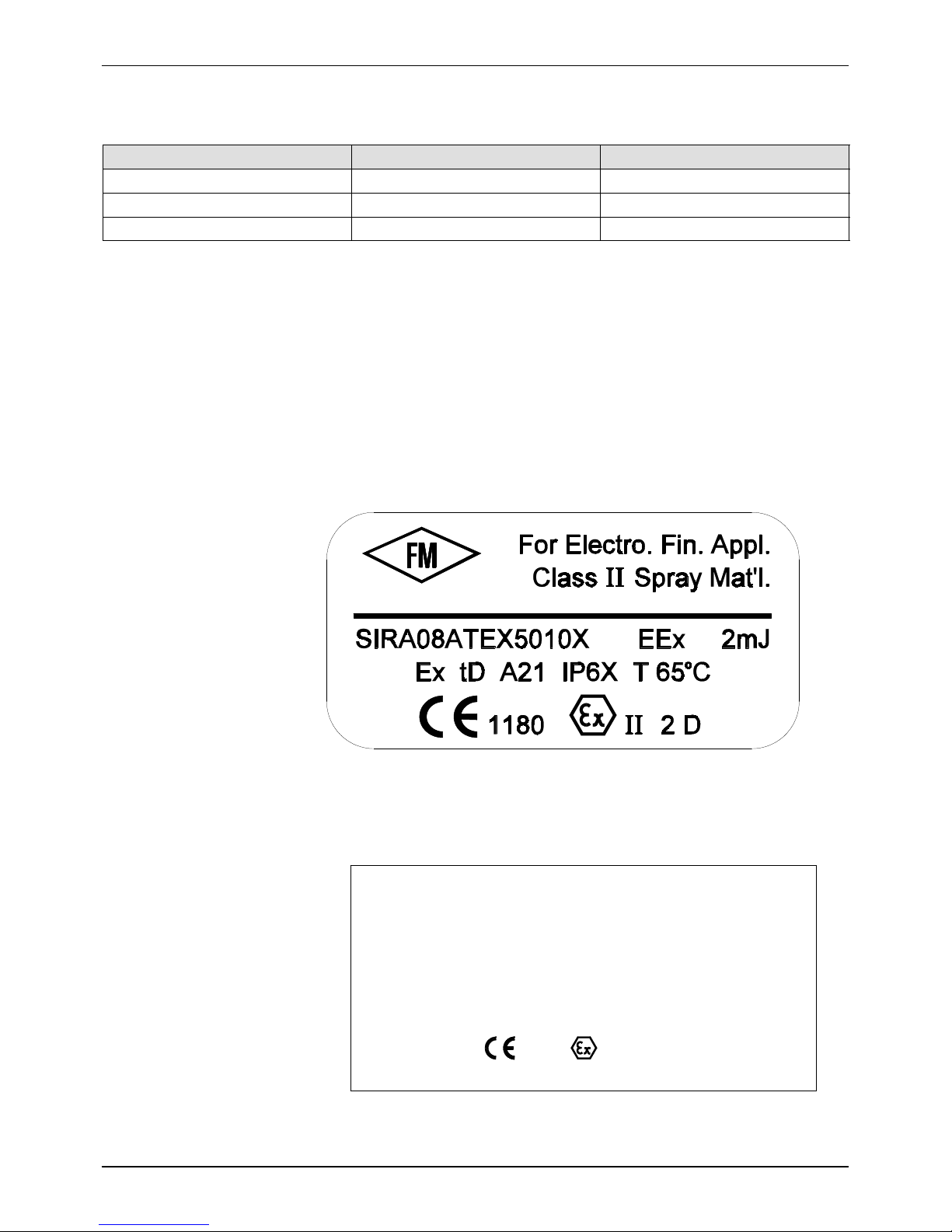
Applicator Certification Label
C
US
APPROVED
Power Unit and Gun Interface Controllers Certification
Label
ELECTROSTATIC HAND--HELD POWDER
SPRAY EQUIPMENT TYPE ENCORE
NORDSON CORPORATION, AMHERST, OHIO U.S.A.
SIRA08ATEX5010XEN 50 050
Ta: + 15_CTO+40_C
PWR UNIT OUTPUT: Vo=24VDC Io=2.75A
INTERFACE OUTPUT: Vo=19VAC Io=1A
Ex tD A22 IP6X
Vn=100--240 VAC, fn = 50/60 Hz
T60_C
r
Pn=85 VA
Part 1102771A
1180 II 3 (2) D
DO NOT OPEN WHEN EXPLOSIVE ATMOSPHERE IS PRESENT
E 2010 Nordson Corporation
Page 13
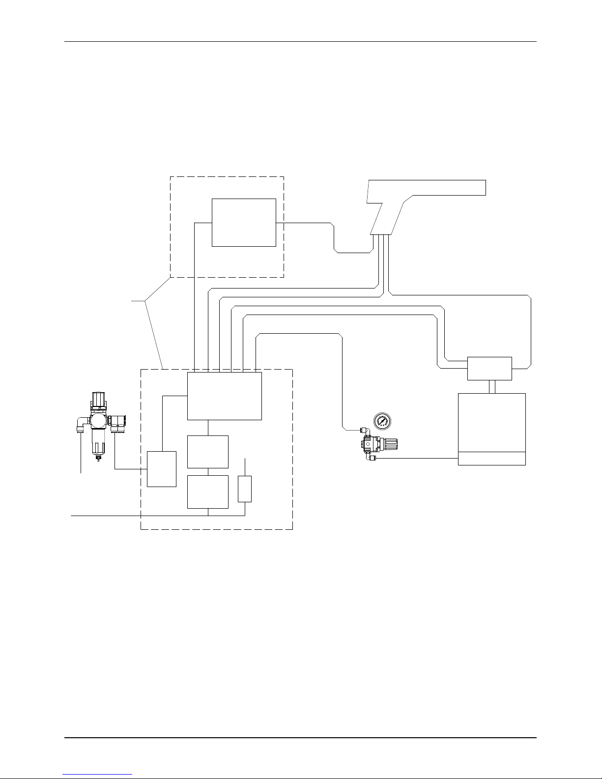
System Connections
System Diagram
NOTE: This diagram does not show system grounds. The system and its
components must all be connected to a true earth ground.
System Setup
2-3
Encore Controller
Filter/Regulator
Input Air
10mm
10mm
AC Power Cord
Reg
85 PSI
Interface
Module
CAN/+24V
Power Unit
Main Control
Air Wash Air
Purge Air
Atomizing Air
iFlow Module
Power
Supply
Switch
Fuses
Board
Flow-Rate Air
Relay*
Fluidizing Air
Gun cable
4mm clear
6mm black
8mm blue
8mm black
6mm blue
Fluidizing Air
Gauge and Regulator
60
40
4
3
80
2
5
20
6
1
0
7
0
BAR
100
psi
* Relay disabled when controller
configured for hopper system
Spray Gun
Powder hose
Pump
Hopper
6mm blue
Figure 2-2 Encore Manual Powder System Block Diagram
Controller Connections
E 2010 Nordson Corporation
The Encore Spray Gun Controller is a two piece unit, consisting of a
interface module and a power unit, connected by a network/power
interconnect cable.
The power unit houses a 24Vdc power supply, circuit board, and iFlowr air
control manifold.
The interface module houses the operator interface panel, which contains
the displays and controls used to make controller function settings and
spray settings, and the spray gun driver board.
Part 1102771A
Page 14
2-4
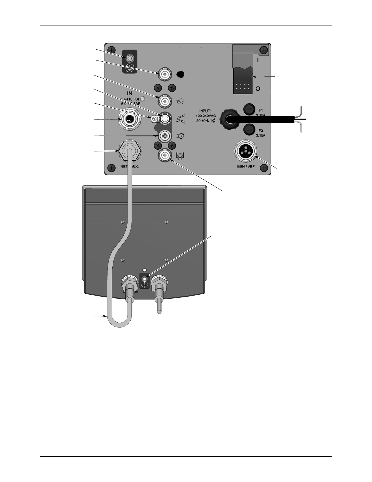
System Setup
Ground
Flow Air
(8 mm)
Atomizing Air
(8 mm)
Electrode Air Wash
Needle Valve
Electrode Air Wash
(4 mm)
Air Supply
(10 mm)
Purge Air (6 mm)
Net
(Manual System)
or Auxiliary
POWER UNIT
INTERFACE MODULE
System Power Switch
L1
(Brown)
L2
(Blue)
GND
(Green/Yellow)
Power Cord
(15 ft)
VBF Power
(Cap if not used)
Fluidizing Air
Check Valve
(8 mm, reduced to 6-mm)
Network/Power
Interconnect
Cable
Figure 2-3 Encore Gun Controller Connections
Gun Cable
(to Gun)
Ground
Part 1102771A
E 2010 Nordson Corporation
Page 15

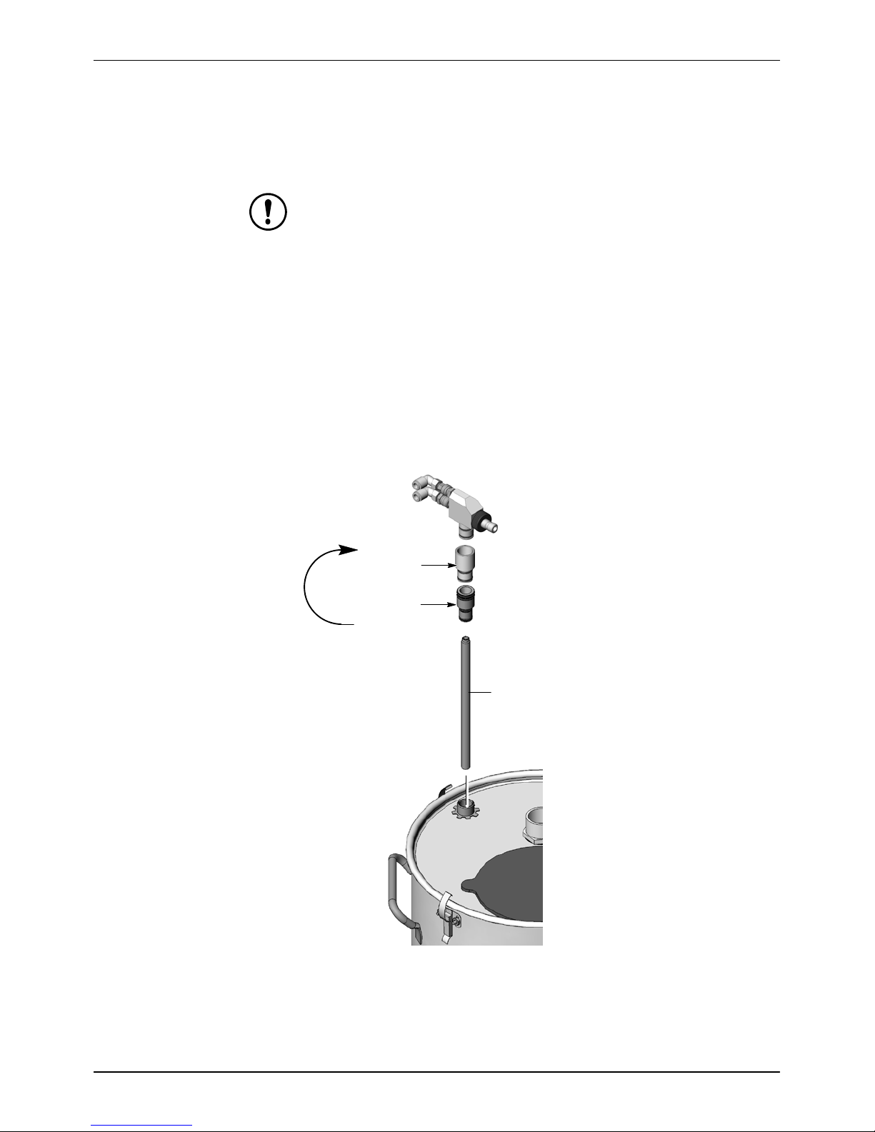
Hopper Installation
1. Unclamp the hopper lid and remove the vent hose and hose clamps.
2. Place the hopper on the cart platform so that the bottom of the fluidizing
3. Connect the 10-mm stem x 6-mm tube reducer to the 10-mm elbow
4. Connect the 6-mm blue fluidizing air tubing to the reducer.
5. Connect the ring-tong terminal on the 1-ft green/yellow ground cable
6. Install the hose clamp over the end of the vent hose and connect the
NOTE: Before turning on the controller interface, route the other end of the
vent hose into the spray booth. This prevents the very fine powder particles
in the vented fluidizing air from contaminating the spray room.
System Setup
2-5
pan fits into the cutout in the cart platform.
fitting on the fluidizing pan.
shipped with the system to the ground stud on the side of the fluidizing
pan, then plug the cable into the grounding socket on the cart base.
hose to the vent stack on the lid. Tighten the clamp to secure the hose.
Vent Stack
Ground
Plug/Socket
Vent Hose
Ground Stud
Fluidizing Air
Fitting
E 2010 Nordson Corporation
Ground
Cable
Figure 2-4 Hopper Installation
Hopper
Fluidizing
Pan
Reducer
Fluidizing
Air
Tubing
Part 1102771A
Page 16
2-6
System Setup
Pump Installation
Pump Mounting
CAUTION: Pump adapter O-rings are conductive silicone, to provide a
ground connection between the pump body and the pickup tube or hopper
lid. Do not replace these O-rings with non-conductive O-rings.
The system is shipped with pump adapter for the Encore pump. The
hopper is shipped with a pump adapter used for other types of pumps. To
mount the pump on the hopper:
1. See Figure 2-5. Pull the pickup tube assembly out of the pump mount.
2. Unscrew the adapter from the pickup tube.
3. Screw the new adapter onto the pickup tube.
4. Re-install the pickup tube assembly into the pump mount then install the
pump into the new adapter with a slight twisting motion.
Replace
With This
Adapter
Remove
This
Adapter
Pickup Tube
Part 1102771A
Figure 2-5 Pump Mounting
E 2010 Nordson Corporation
Page 17
Pump Connections
System Setup
2-7
1. Plug the blue atomizing air and black flow-rate air tubing into the pump
tube fittings as shown in Figure 2-6.
2. Push the powder feed hose onto the barbed throat holder.
Blue 8-mm Tubing (Atomizing AIr
Quick-Disconnect Coupling
Black 8-mm Tubing
(Flow-Rate Air)
Figure 2-6 Pump Connections
)
Throat Holder
Powder Hose
NOTE: The pump is equipped with quick-connect couplings that allow you
to quickly disconnect the air tubing when cleaning or repairing the pump.
Pull back on the knurled coupling rings to disconnect them.
E 2010 Nordson Corporation
Part 1102771A
Page 18
2-8
System Setup
Spray Gun Connections
Unpack the spray gun. Uncoil the spray gun cable and the included 4-mm
clear and 6-mm black air tubing. Make the following connections:
Gun Cable
SeeFigure2-7.
1. Feed the spray gun cable into the back of the tower and up through the
top front. This will allow you to bundle the cable with the purge and
electrode air wash tubing.
2. Connect the cable to the interface module receptacle. The cable plug
and receptacle are keyed.
3. Thread the cable nut onto the receptacle and tighten the nut securely.
Gun Cable
Figure 2-7 Connecting the Gun Cable to the Controller Interface Module
Part 1102771A
Net Cable
(To Power Unit)
E 2010 Nordson Corporation
Page 19
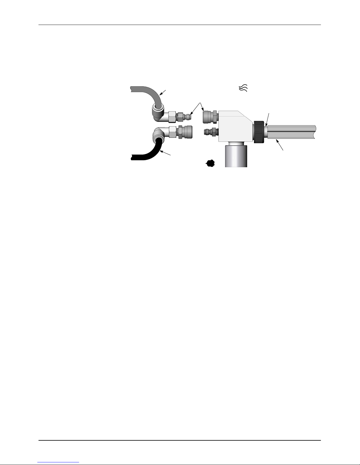
Spray Gun Air Tubing Connections
See Figures 2-8 and 2-9.
Clear 4-mm and black 6-mm air tubing is shipped with the spray gun.
1. Connect the 6-mm black air tubing to the quick-disconnect fitting in the
gun handle.
2. Connect the 4-mm clear electrode air wash tubing to the barbed fitting in
the gun handle.
4-mm Clear
Electrode Air Wash
Tubing
System Setup
2-9
Figure 2-8 Connecting Purge and Air Wash Tubing to the Spray Gun
3. Route the air tubing around the cart to the rear of the tower.
4. Connect the 4-mm clear electrode air wash tubing to the electrode air
wash quick-disconnect fitting.
5. Connect the 6-mm black purge air tubing to the purge air
quick-disconnect fitting.
4-mm Clear
Electrode Air
Wash Tubing
6-mm Black
Purge Air Tubing
6-mm Black
Purge Air Tubing
Figure 2-9 Connecting Purge and Air Wash Tubing to the Controller
E 2010 Nordson Corporation
Part 1102771A
Page 20
2-10
System Setup
Spray Gun Powder Tubing Connection
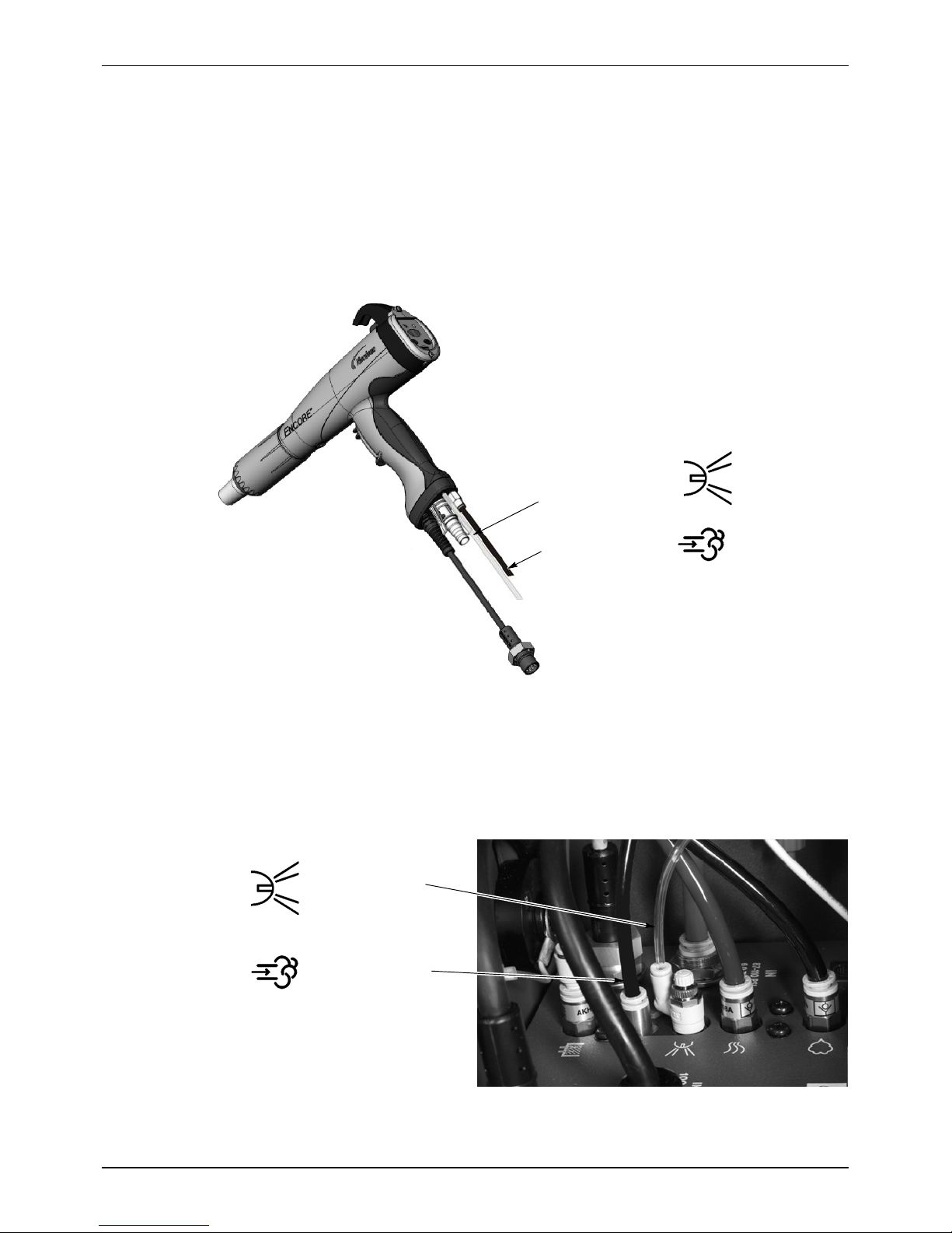
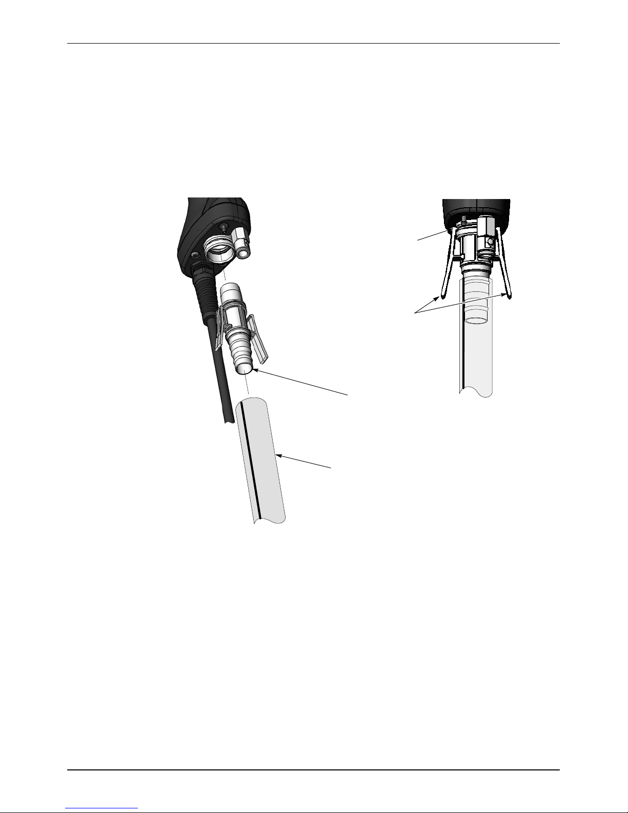
See Figure 2-10.
Push the barbed hose adapter into the end of the powder feed hose, then
plug the adapter into the receptacle in the bottom of the spray gun handle.
Make sure the adapter clips snap into the groove in the receptacle.
(To quickly remove the hose adapter and hose from the gun, press in on the
bottom ends of the clips to release them from the groove.)
Make sure clips
are seated in
groove
Press IN on
clips when
installing or
removing
adapter
Figure 2-10 Connecting the Powder Tubing to the Spray Gun
Bundling Tubing and Cable
Use the sections of black spiral wrap supplied with the system to bundle
together the spray gun cable, air tubing, and powder feed tubing.
Barbed Hose
Adapter
Powder Tubing
11-mm or
to Pump
1
/2in.
Part 1102771A
E 2010 Nordson Corporation
Page 21
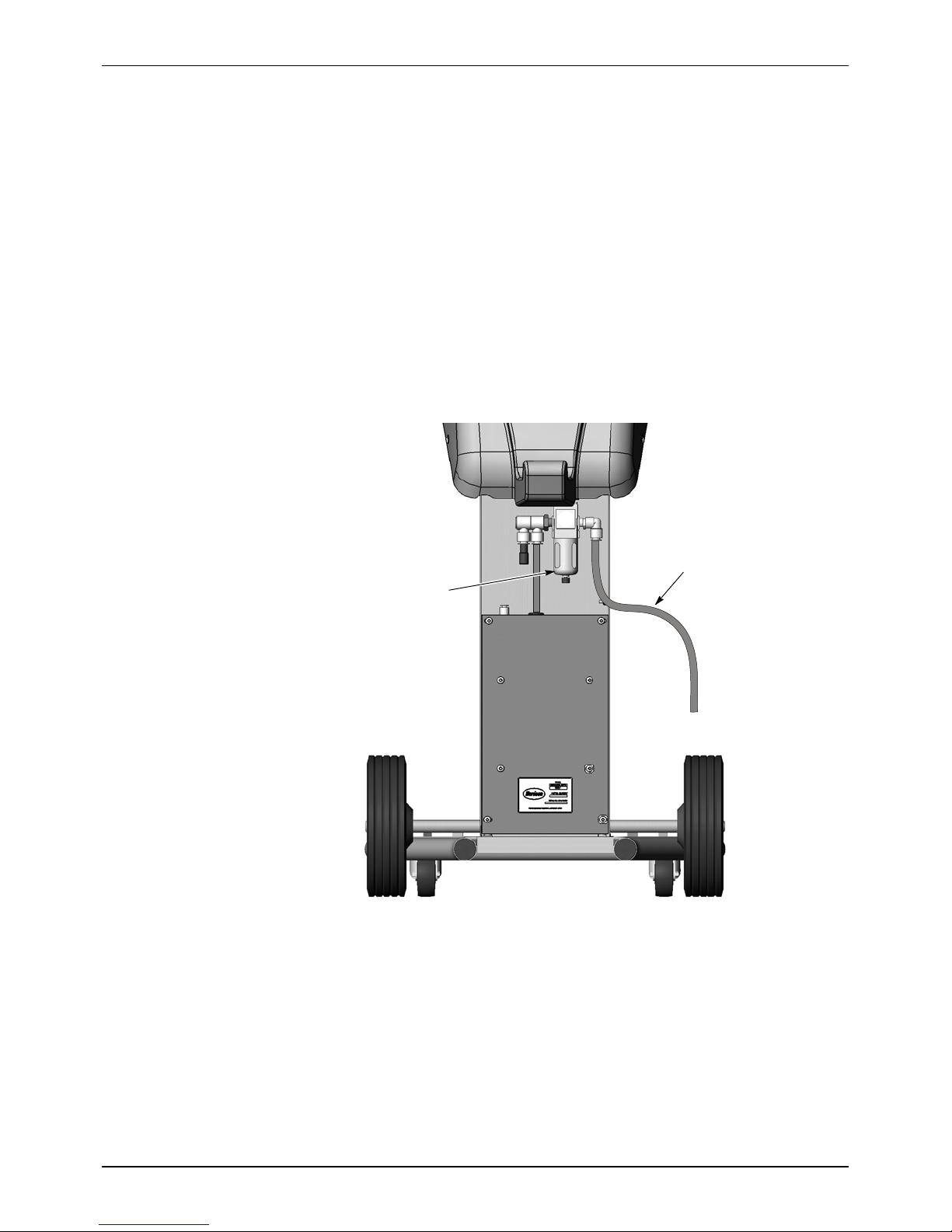
System Air and Electrical Connections
System Air Supply
See Figure 2-11. Connect 10-mm air tubing from your compressed air
supply to the system air filter in the power unit cabinet. The air supply
pressure should be 6.0--7.6 bar (87--110 psi).
An optional input air kit with connectors, couplings, and 20 ft of 10 mm
tubing is available. Refer to the Parts section for the kit contents and
ordering information.
NOTE: Compressed air should be supplied from an air drop equipped with
a self-relieving shutoff valve. The air must be clean and dry. A refrigerant
or desiccant-type air drier and air filter/separators are recommended.
System Setup
2-11
Air Filter
Regulator
Figure 2-11 System Air Supply Connection
10-mm
Air Tubing
E 2010 Nordson Corporation
Part 1102771A
Page 22
2-12
System Setup
Electrical Connections
System Ground
The controller is rated for 100--240 Vac at 50/60 Hz, single phase.
Wire the system power cord to a customer-supplied three-prong plug.
Connect the plug to an electrical outlet that supplies the rated power.
Wire Color Function
Blue N (neutral)
Brown L (hot)
Green/Yellow GND (ground)
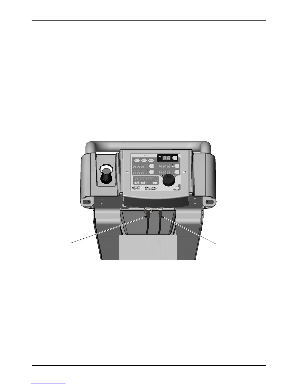
See Figure 2-12. Use the ground cable attached to the lower ground stud
on the cart to ground the system to a true earth ground.
Part 1102771A
Figure 2-12 System Ground Connection
E 2010 Nordson Corporation
Page 23

Operation
3-1
Section 3
Operation
WARNING: Allow only qualified personnel to perform the following tasks.
Follow the safety instructions in this document and all other related
documentation.
WARNING: This equipment can be dangerous unless it is used accordance
with the rules laid down in this manual.
WARNING: All electrically conductive equipment in the spray area must be
grounded. Ungrounded or poorly grounded equipment can store an
electrostatic charge which can give personnel a severe shock or arc and
cause a fire or explosion.
European Union, ATEX, Special Conditions for Safe Use
1. The Encore Manual Applicator shall only be used with associated
Encore Interface Control Unit and Encore Controller Power Unit.
2. Equipment may only be used in areas of low impact risk.
Daily Operation
NOTE: The controller is shipped with a default configuration that will allow
you to start spraying powder as soon as you finish setting up the system.
Refer to Controller Configuration on page 3-17 for a list of the defaults and
instructions on how to change them, if desired.
Startup
1. Turn on the spray booth exhaust fan.
2. Make sure the vent hose is connected to the vent stack on the hopper
lid and routed into the spray booth.
3. Turn on the system air supply.
4. Remove the black rubber fill plug from the hopper lid and fill the hopper
half full of powder.
E 2010 Nordson Corporation
NOTE: Do not fill the hopper more than half full. The fluidizing air will
cause the powder to increase in volume.
Part 1102771A
Page 24
3-2
Operation
Startup (contd)
Controller
Power
Switch
Figure 3-1 System Controls
Fluidizing Air
Regulator/Gauge
On
Off
Controller
Interface
Standby
Button
Spray
Gun
Interface
5. Make sure the spray gun is not triggered, then turn on controller power.
The displays and icons on the controller interface and gun interface will
light.
6. The fluidizing air turns on when the interface is turned on. Adjust the
fluidizing air pressure to 0.3--0.7 bar (5--15 psi). The pressure should be
just enough so the powder in the hopper “boils” gently. Fluidize the
powder for 5--10 minutes before spraying powder.
7. Point the spray gun into the booth and press the trigger to start spraying
powder.
NOTE: If using Total F low mode, the total air setpoint must be greater than
zero or you will not be able to set % Flow Air and the gun will not spray
powder. R efer to page 3-13 for more information.
8. Select the desired preset and start production.
The controller interface displays actual output when the gun is spraying and
the current preset setpoints when the gun is off.
Factory Set Presets
Presets are recipes with electrostatic and powder flow setpoints for a
particular part or application. 20 presets are available. Presets 1--3 are
setup for you. Refer to Preset Setup on page 3-10 for preset setting
instructions.
Setpoints
Preset Electrostatic Output and Powder Flow
1 Max kV, 150 g/min (20 lb/hr) 100 30 45 3.0
2 Max kV, 300 g/min (40 lb/hr) 100 30 75 3.0
3 Select Charge 3 (deep recess), 150 g/min (20 lb/hr) 100* 60* 45 3.0
* Select Charge Mode settings are factory set and cannot be changed.
kV A %
Part 1102771A
E 2010 Nordson Corporation
Page 25
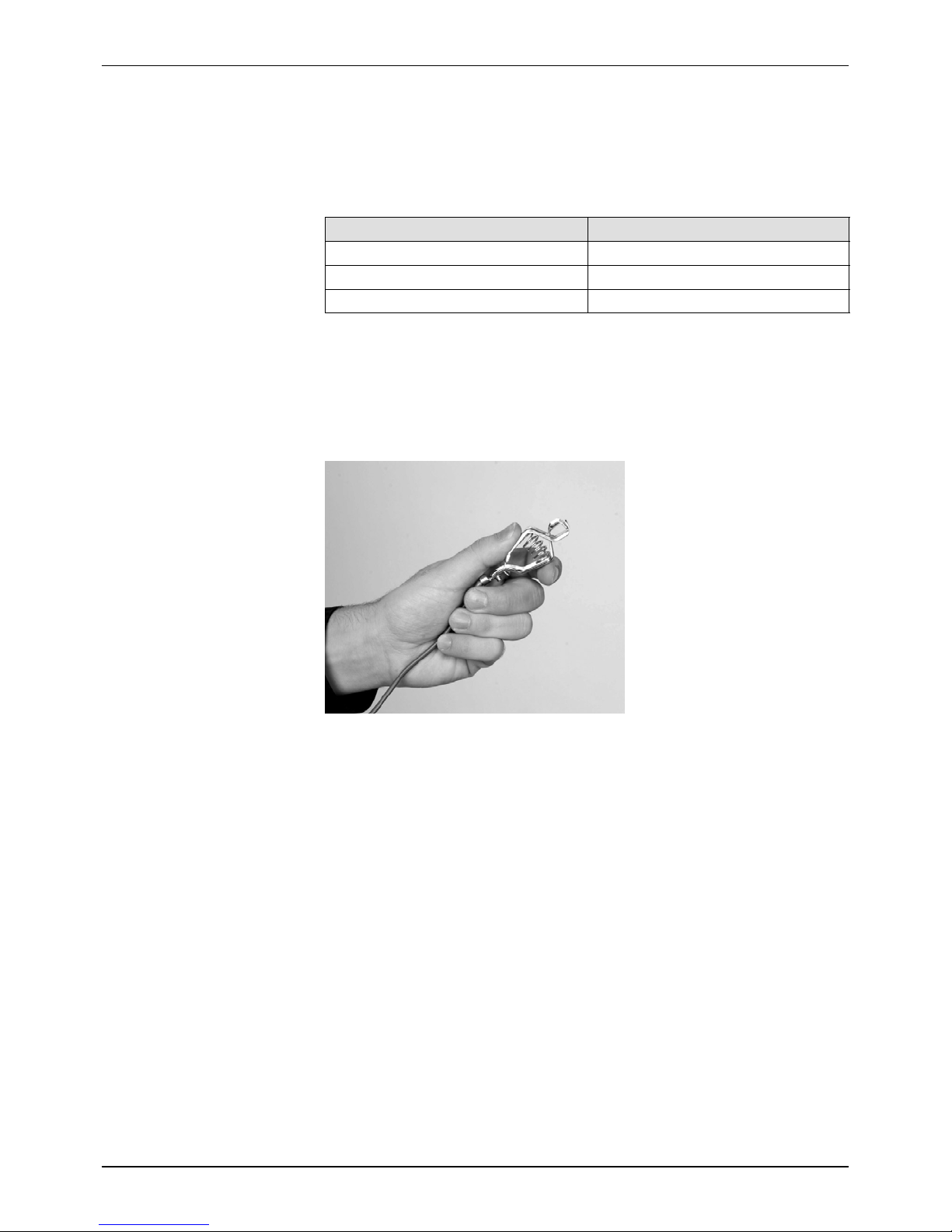
Spray Gun Operation
Operation
3-3
The spray gun interface and settings trigger allow you to change presets or
powder flow settings, or purge the gun as needed, without using the
controller Interface.
Preset
Mode
Icon
Display
Mode
Button
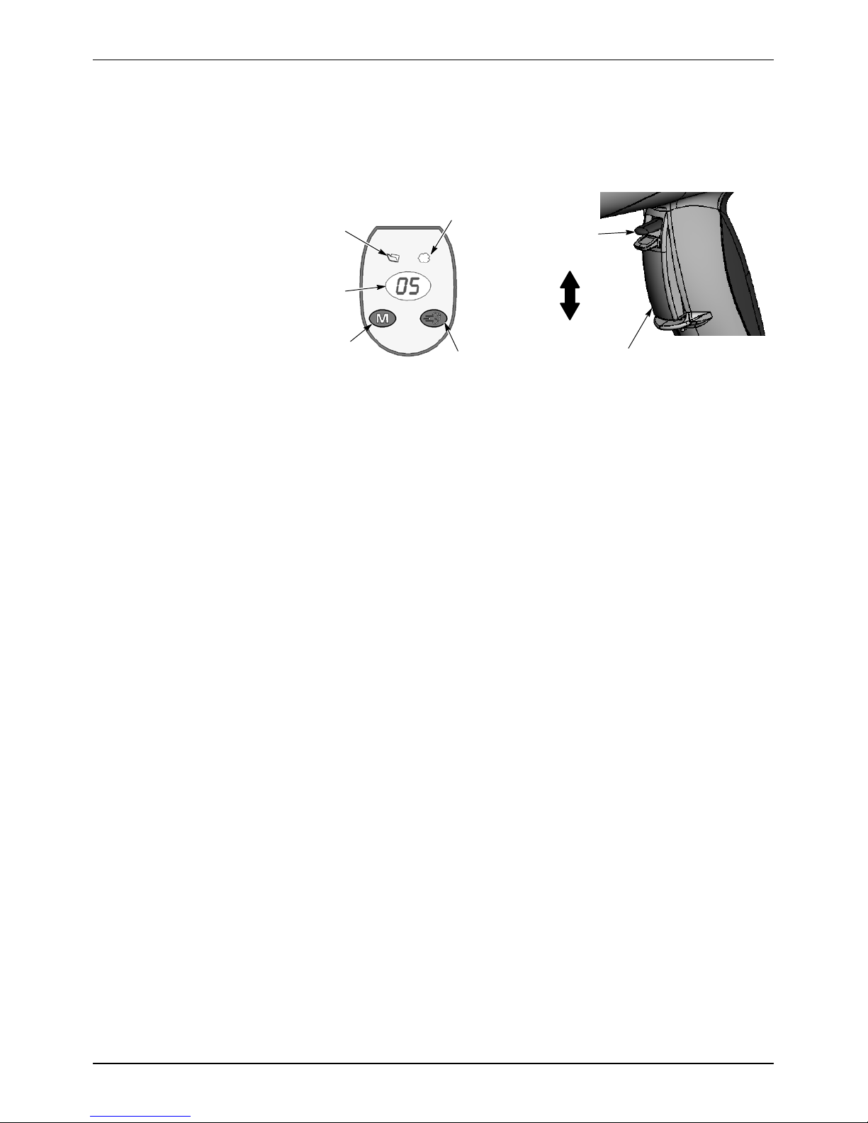
Spray Gun
Interface
Figure 3-2 Gun Controls
Flow
Mode Icon
Purge
Button
Settings
Trigger
Increase/On
Decrease/Off
Main Trigger
Changing Presets with the Settings Trigger
1. See Figure 3-2. Release the main trigger. Presets cannot be changed
while the gun is triggered on.
2. Press the Mode button until the Preset Mode Icon is lit. The display
shows the current preset number.
3. Push the settings trigger up or down until the desired preset number is
displayed on the spray gun interface.
NOTE: Unprogrammed preset numbers (presets where all setpoints are
zero) are automatically skipped.
4. Press the main trigger. The system now sprays with the new preset
settings.
Changing Powder Flow with the Settings Trigger
1. See Figure 3-2. Press the Mode button until the Flow Mode icon is lit.
2. Push the settings trigger up or down to change the flow setpoint. This
can be done without releasing the main trigger.
The powder flow immediately changes. The new flow setpoint is
displayed on both the spray gun interface and the controller interface.
NOTE: In Tot al Flow mode, the total air setpoint must be greater than zero
or you will not be able to set % Flow Air and the gun will not spray powder.
Refer to page 3-13 for more information.
Purging the Gun
1. See Figure 3-2. Point the gun into the booth and release the main
trigger.
2. Press the Purge button. The purge will continue as long as the purge
button is pressed.
E 2010 Nordson Corporation
Part 1102771A
Page 26
3-4
Operation
Standby Button
NOTE: If the settings trigger is configured for Purge, then pressing up or
down on the settings trigger purges the gun. Refer to Controller
Configuration on page 3-17 for configuration instructions.
Purge the gun periodically to keep the powder path inside the spray gun
clean. The purge length and frequency needed depend on the application.
NOTE: The purge air only cleans the spray gun powder path. To purge the
powder hose, disconnect it from the pump and the gun, place the gun end
inside the booth, and blow it out from the pump end with compressed air.
Use the Standby button shown in Figure 3-1 to shut off the interface and
disable the spray gun during breaks in production. When the controller
interface is off the spray gun cannot be triggered, and the spray gun
interface is disabled.
To shut off the controller power, use the controller power switch on the
power unit.
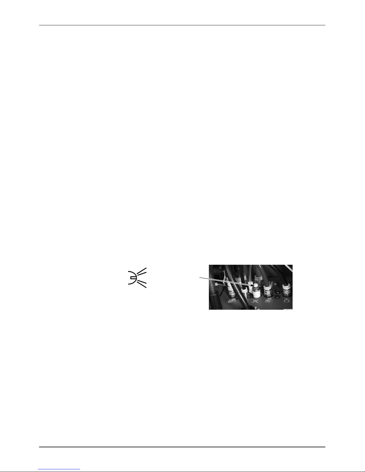
Electrode Air Wash Operation
Electrode air wash air continually washes the spray gun electrode to
prevent powder from collecting on it. Electrode air wash turns on and off
automatically when the spray gun is triggered on and off.
The air flow needle valve on the power unit is set at the factory for the most
common applications (1be adjusted if needed.
Electrode Air Wash
Figure 3-3 Electrode Air Wash Needle Valve Location
Changing Flat Spray Nozzles
WARNING: Release the spray gun trigger, turn off the interface, and
ground the electrode before performing this procedure. Failure to observe
this warning could result in a severe electrical shock.
1
Needle Valve
/2turns CCW from fully closed position), but can
Part 1102771A
1. Purge the spray gun and press the standby button to turn off the
interface and prevent accidental gun triggering.
2. Unscrew the nozzle nut counterclockwise.
3. Pull the flat spray nozzle off the electrode assembly.
E 2010 Nordson Corporation
Page 27
Operation
3-5
NOTE: Re-install the electrode if it comes out of the powder outlet tube.
4. Install a new nozzle on the electrode assembly. The nozzle is keyed to
the electrode assembly. Do not bend the electrode wire.
5. Screw the nozzle nut onto the gun body clockwise until finger-tight.
Nozzle Nut
Figure 3-4 Changing a Flat Spray Nozzle
Flat Spray Nozzle
Changing Deflectors or Conical Nozzles
WARNING: Release the spray gun trigger, turn off the interface, and
ground the electrode before performing this procedure. Failure to observe
this warning could result in a severe electrical shock.
1. Purge the spray gun and press the standby button to turn off the
interface and prevent accidental gun triggering.
2. Gently pull the deflector off the electrode assembly. If only changing the
deflector, install the new one on the electrode assembly, being careful
not to bend the electrode wire.
3. To change the entire nozzle, unscrew the nozzle nut counterclockwise.
4. Pull the conical nozzle off the electrode assembly.
NOTE: If the electrode assembly comes out of the powder outlet tube,
re-install it.
5. Install a new conical nozzle on the electrode assembly. The nozzle is
keyed to the electrode assembly.
Electrode Assembly
Electrode Holder
Deflector
Figure 3-5 Changing a Conical Nozzle
E 2010 Nordson Corporation
6. Screw the nozzle nut onto the gun body clockwise until finger-tight.
7. Install a new deflector on the electrode assembly. Do not bend the
electrode wire.
Electrode
Nozzle Nut
Assembly
Nozzle
Part 1102771A
Page 28
3-6
Operation
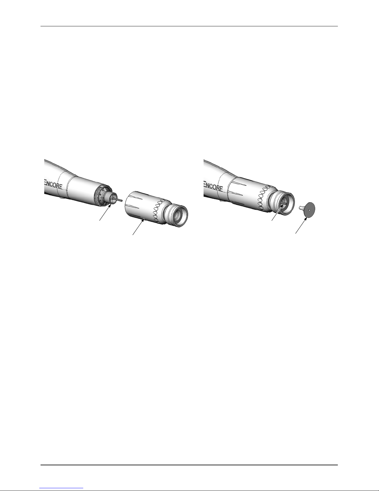
Installing the Optional Pattern Adjuster Kit
An optional pattern adjuster kit with integral conical nozzle can be installed
in place of a standard flat spray or conical nozzle.
NOTE: Deflectors are not included with the pattern adjuster kit; they must
be ordered separately. The 38-mm deflector cannot be used with the kit.
1. Remove the deflector, nozzle nut, and conical nozzle, or the nozzle nut
and flat spray nozzle.
2. Blow off the electrode assembly.
3. Install the integral conical nozzle onto the electrode assembly and screw
the nozzle nut clockwise until finger-tight
4. Install a 16, 19, or 26-mm deflector onto the electrode holder.
Electrode
Assembly
Figure 3-6 Pattern Adjuster Kit Installation
Pattern
Adjuster Kit
Shutdown
1. Purge the spray gun by pressing the Purge button until no more powder
is blown from the gun.
2. Press the standby button to turn off the spray gun and interface.
3. Turn off the system air supply and relieve the system air pressure.
4. If shutting down for the night or a longer period of time, move the power
unit switch to the OFF position to shut off system power.
5. Perform the Daily Maintenance procedures on page 3-7.
Electrode Holder
Deflector
Part 1102771A
E 2010 Nordson Corporation
Page 29

Maintenance
WARNING: Allow only qualified personnel to perform the following tasks.
Follow the safety instructions in this document and all other related
documentation.
WARNING: Before performing the following tasks, turn off the controller
and disconnect system power. Relieve system air pressure and disconnect
the system from its input air supply. Failure to observe this warning may
result in personal injury.
NOTE: If necessary, remove O-rings and clean parts using a cloth
dampened with isopropyl or ethyl alcohol. Do not immerse plastic parts in
alcohol. Do not get alcohol on the O-rings; it will cause them to swell. Do
not use any other solvents.
Perform the Shutdown procedure before performing these procedures.
Component Procedure
Spray Gun
(Daily)
1. Point the spray gun into the booth and purge the spray gun.
2. Shut off the system air supply and power.
Operation
3-7
Pump
(Daily)
Controller
(Daily)
System Air
Filter
(Periodically)
System
Grounds
Hopper and
Pickup Tube
(Periodically)
3. Disconnect the powder feed hose adapter and blow out the spray gun powder path.
4. Disconnect the powder feed hose at the pump. Place the gun end of the hose inside
the booth and blow out the hose from the pump end.
5. Remove the nozzle and electrode assembly and clean them with low-pressure
compressed air and clean cloths. Check them for wear and replace if necessary.
6. Blow off the gun and wipe it down with a clean cloth.
1. Disconnect the pump air hoses and remove the pump from the pickup tube.
2. Disassemble the pump and clean all parts using low-pressure compressed air.
3. Replace any worn or damaged parts.
Refer to the Encore Powder Pump manual for instructions and spare parts.
Blow off the cart and controller with a blow gun. Wipe powder off the controller with a
clean cloth.
Check the system air filter/regulator inside the cart tower. Drain the filter and change
the filter element as needed. See Figure 2-11 for the filter location.
Refer to Parts for the correct filter element. Older units had a white 5 micron particulate
filter element, new units have a yellow 0.3 micron oil/water filter element. The elements
are not interchangeable. If necessary, compare the OEM part number on the side of the
filter/regulator with the OEM part number in the part description to ensure that you order
the correct element.
Daily: Make sure the system is securely connected to a true earth ground before
spraying powder.
Periodically: Check all system ground connections.
Empty the hopper and clean the interior. Remove and clean the pickup tube. Clean the
fluidizing plate and inspect it for signs of air contamination. If the plate is discolored and
appears to be contaminated, replace it. Check your air supply and correct any
contamination problems.
E 2010 Nordson Corporation
Part 1102771A
Page 30

3-8
Operation
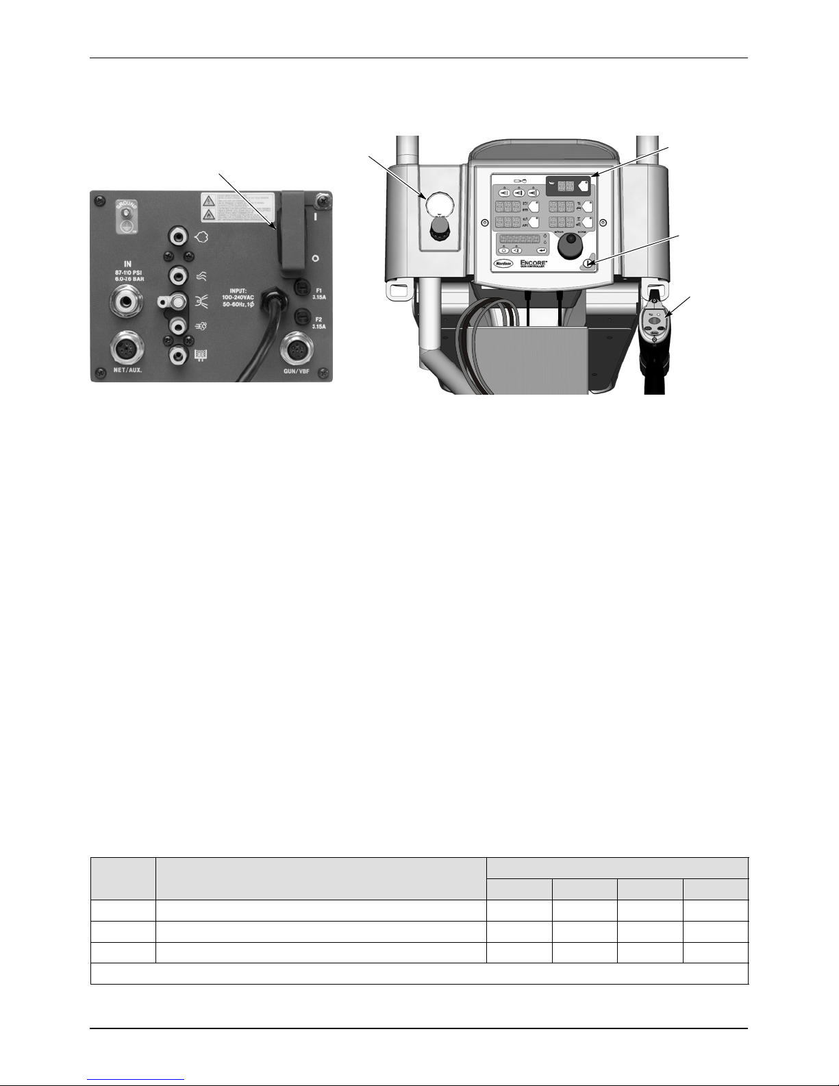
Using the Controller Interface
Use the controller interface to make preset settings, view help codes,
monitor system operation, and configure the controller.
Gun Triggered On Indicator
Select Charge
Modes
KV Setpoint
Current
Preset
Number
Button
LEDs
Preset Select
Button
%ofFlowor
Flow Air Flow
Setpoint Button
A
Setpoint
Function/Help
Display
Help
Button
Nordson Button
(Configuration)
Figure 3-7 Controller Interface
Setpoint Icons
TotalFlowor
Atomizing Air
Flow Setpoint
Button
Rotary
Knob
Standby Button
View Button
Enter Button
The Setpoint icons light to indicate the configured or selected setpoints.
Setpoints include Select Charge, KV, A, % of Flow and Tot al Fl ow, or
Flow Air and Atomizing Air flow rates.
To select a Preset or change a Preset setpoint, press the Preset Select
button or a Setpoint button. The button LED lights to indicate that it is
selected.
Use the Rotary Knob to change the selected setpoint: clockwise to
increase, counter-clockwise to decrease. The setpoints reset to the
minimum if increased past their maximum.
Part 1102771A
Selecting a Setpoint to Change Changing a Selected Setpoint
Figure 3-8 Selecting and Changing Setpoints
E 2010 Nordson Corporation
Page 31

Help Codes
Operation
The Help icon in the Function/Help display lights if a problem occurs.
Display Codes Clear Codes
Figure 3-9 Displaying and Clearing Help Codes
Press the Help button to display the Help codes. The controller
retains the last 5 codes in memory. Rotate the knob to scroll through the
codes. The display blanks if there is no activity for 5 seconds.
To clear the Help codes, scroll through them until CLr is displayed,
then press the Enter button. The Help icon stays lit until the controller
clears the codes.
3-9
Refer to Section 4, Troubleshooting for help code troubleshooting, general
system troubleshooting, resistance and continuity tests, and system wiring
diagrams.
Maintenance Timer, Configuration, and Versions
Press the View button and turn the rotary knob to view, in the
following order: Maintenance hours, Total hours, Gun Controller (GC), Gun
Display (Gd), iFlow Module (FL) software versions and Hardware version
(Hd). The Maintenance hour timer is set through the Controller
Configuration on page 3-17. Total hours cannot be reset.
The Help icon lights if the maintenance timer is set and runs out.
To reset the maintenance timer, press the View button.
The Timer icon lights when the maintenance hours are displayed.
While they are displayed, press the Enter button.
E 2010 Nordson Corporation
Figure 3-10 Displaying Maintenance Hours
Part 1102771A
Page 32

3-10
Operation
Preset Setup
Selecting Presets
Presets are recipes with electrostatic and powder flow settings for specific
parts or applications. The operator can quickly change spray settings
simply by changing the preset number.
The controller can store 20 presets. Presets 1, 2, and 3 are programmed at
the factory for the most common applications. Refer to page 3-2 for their
setpoints. These setpoints can be adjusted as needed. Presets 4--17 can
be programmed as needed.
1. Press the Preset button. The button LED lights.
2. Turn the rotary knob. The preset number increases from 1 to 20 then
rolls over to 1.
The setpoints for the selected preset are displayed when the gun is off.
Figure 3-11 Preset Select
Electrostatic Settings
Electrostatic output can set in Select Charge mode, Custom mode, or
Classic mode.
Select ChargerMode
The Select Charge modes are non-adjustable electrostatic settings. The
LEDs above the Select Charge mode buttons indicate the selected mode.
The Select Charge Modes and electrostatic setpoints are:
Mode 1 Re-Coat 100 kV, 15 A
Mode 2 Metallics 50 kV, 50 A
Mode 3 Deep Recesses 100 kV, 60 A
Mode 1 Mode 2 Mode 3
Preset Button
Part 1102771A
Figure 3-12 Select Charge Mode
NOTE: If the operator tries to adjust kV or A values while a Select Charge
mode is selected, the controller will switch to Custom or Classic mode.
E 2010 Nordson Corporation
Page 33

Custom Mode
Operation
Custom Mode is the factory default mode. In this mode, both kV and A
can be adjusted independently. The STD and AFC icons are not displayed.
NOTE: Refer to Controller Configuration on page 3-17 for a list of the mode
defaults and configuration instructions.
1. To set or change the kV setpoint, press the KV button. The button LED
lights to show that kV is selected.
2. Turn the rotary knob to increase or decrease the kV setpoint. The
setpoint is automatically saved if it does not change for 3 seconds, or
when any button is pressed.
3. To set or change the A setpoint, press the A button. The button LED
lights to indicate that A is selected.
4. Turn the rotary knob to increase or decrease the A setpoint. The
setpoint is automatically saved if it does not change for 3 seconds, or
when any button is pressed.
NOTE: The default A range is 10--50 A. The limits of the range can be
adjusted. Refer to Controller Configuration on page 3-17.
3-11
Classic Mode
S When the gun is not triggered the KV and A setpoints are displayed.
S When the gun is triggered the actual KV and A outputs a re displayed.
Custom Mode -- Preset Setpoints
Figure 3-13 Custom Mode -- Setpoints and Gun Triggered Displays
To use Classic mode, the controller must be configured for it. Refer to
Controller Configuration on page 3-17.
In Classic mode you can choose to control kV (STD) output or A(AFC)
output, but not both at the same time.
Custom Mode -- Gun Triggered
E 2010 Nordson Corporation
Classic Standard (STD) Mode
Use the Standard mode to set kV. In Standard mode you cannot set A.
1. To set the kV setpoint, press the KV button. The button LED lights to
show that kV is selected.
Part 1102771A
Page 34

3-12
Operation
Classic Standard (STD) Mode (contd)
2. Turn the rotary knob to increase or decrease the kV setpoint. The
setpoint is automatically saved if it does not change for 3 seconds, or
when any button is pressed.
S When the gun is not triggered the kV setpoint is displayed.
S When the gun is triggered the actual kV and A outputs are displayed.
STD Mode -- kV Setpoint
Figure 3-14 STD Mode -- Setpoint and Gun Triggered Displays
STD Mode -- Gun Triggered
Classic AFC Mode
Use the AFC mode to set A output limits. In AFC mode you cannot adjust
KV, it is automatically set to 100 KV.
1. To set the A setpoint, press the A button. The button LED lights to
show that A is selected.
2. Turn the rotary knob to increase or decrease the A setpoint. The
setpoint is automatically saved if it does not change for 3 seconds, or
when any button is pressed.
NOTE: The default A range is 10--50 A. The limits of the range can be
adjusted. Refer to Controller Configuration on page 3-17.
S When the gun is not triggered the A setpoint is displayed.
Part 1102771A
AFC Mode -- A Setpoint AFC Mode -- Gun Triggered
Figure 3-15 AFC Mode -- Setpoint and Gun Triggered Displays
E 2010 Nordson Corporation
Page 35

Powder Flow Settings
Two modes of powder flow control are available:
Smart Flow -- This is the factory default mode. In this mode, you set Total
Air (powder velocity) and Flow Air % (powder flow) setpoints. The controller
automatically adjusts flow-rate and atomizing air flows to the pump based
on the setpoints. When the controller is configured for Smart Flow mode,
the % and icons are lit.
Classic Flow -- This is the standard method of setting powder flow and
velocity, by setting flow air and atomizing air flow separately and balancing
them manually for optimum results. When the controller is configured for
Classic Flow mode, the flow and atomizing air icons are lit.
NOTE: Refer to Controller Configuration on page 3-17 for a list of the mode
defaults and configuration instructions.
%
Figure 3-16 Powder Flow Icons
Operation
Flow Air Atomizing AirFlow Air % Total Air
3-13
Smart Flow Mode Settings
In Smart Flow mode, Total Flow sets the velocity of the powder flow, while
Flow Air % sets the powder flow rate. Powder velocity is inversely related to
transfer efficiency; the higher the velocity the lower the transfer efficiency.
When making Smart Flow settings, set the Total Flow setpoint first to obtain
the desired pattern size and penetration, then set the Flow Air % setpoint for
the desired powder flow.
Flow Air %: 0--100%. The actual percentage range available varies
depending on the total air setpoint and the maximum and minimum outputs
for flow and atomizing air.
Total Flow : 2.55--10.2 M
1.5--6.0 SCFM, minimum 0.1 SCFM increments.
See Tables 3-1 and 3-2 for examples of possible Smart Flow settings and
their equivalents in Atomizing and Flow-rate Air pressures and flows.
Figure 3-17 shows the effects of changes in Total Flow and Flow Air %
settings.
The Smart Flow tables provide a range of possible Total Flow and Flow Air
% setpoints. Read across to the vertical axis for the equivalent atomizing
air flows and pressures. Read down to the horizontal axis for the equivalent
flow-rate air flows and pressures.
3
/HR, minimum 0.17 M3/HR increments, or
E 2010 Nordson Corporation
The tables show that as you increase Total Flow powder velocity increases
while the maximum Flow Air % remains the same. Conversely, for a given
Total Flow setting, each increase in Flow Air % increases powder flow.
Part 1102771A
Page 36

3-14
Operation
Smart Flow Mode Settings (contd)
Increase velocity,
no change in flow
50% Flow Air % Setpoint
3.00 Total Flow Setpoint
Increase flow,
no change in velocity
Figure 3-17 Reading the Smart Flow Tables
Max Flow
Max Velocity
Setting Smart Flow Setpoints
To set flow air % or total flow :
1. Press the % or button. The LED on the selected button lights.
2. Turn the knob to increase or decrease the setpoint. The setpoint is
automatically saved if it does not change for 3 seconds or when any
button is pressed.
NOTE: If Total Flow is set to zero, the Flow Air % setpoint cannot be set to
anything but zero, and powder cannot be sprayed. To set Flow Air %, set
Total Flow to a value greater than zero.
S When the spray gun is not triggered the setpoints are displayed.
S When the spray gun is triggered the displays show actual flows.
Flow Air %
3
Total Flow Air in M
Figure 3-18 Smart Flow Mode -- Flow Air % or Total Flow
/HR or SCFM
Part 1102771A
E 2010 Nordson Corporation
Page 37

Smart Flow Settings -- Metric Units
A
AirFlowSettings
:
g
P
owder
Out
put
g
/
150g/mi
n
Operation
3-15
0.4 0.85 X X
0.6 1.27 X
0.9 1.70
1.2 2.12
1.6 2.55
33%
2.55
29%
2.97
25%
3.40
50%
2.54
43%
2.97
37%
3.39
33%
3.82
Powder Velocity (M3/Hr)
Sure Coat w/100+ Pump: z
(Total Flow)
Low <3.40
Soft 3.40--4.25
Medium 4.25--5.53
1.0 bar Atomizing
2.0 bar Flow
150
Firm 5.53--7.23
High >7.23
Max. Powder Flow Rate: L
Table 3-1 Smart Flow Settings -- Metric Units
67%
2.55
57%
2.97
50%
3.40
45%
3.82
40%
4.25
71%
2.97
63%
3.39
55%
3.82
50%
4.24
45%
4.67
75%
3.40
67%
3.82
60%
4.25
55%
4.67
50%
5.10
78%
3.82
70%
4.24
64%
4.67
58%
5.09
54%
5.52
80%
4.25
73%
4.67
67%
5.10
62%
5.52
57%
5.95
82%
4.67
75%
5.09
69%
5.52
64%
5.94
60%
6.37
ir Flow Settings:
:
min.
.
83%
5.10
77%
5.52
71%
5.95
67%
6.37
63%
6.80
85%
5.52
79%
5.94
73%
6.37
69%
6.79
65%
7.22
86%
5.95
80%
6.37
75%
6.80
71%
7.22
67%
7.65
87%
6.37
81%
6.79
76%
7.22
72%
7.64
68%
8.07
88%
6.80
l
82%
7.22
78%
7.65
74%
8.07
70%
8.50
1.9 2.97
2.3 3.40
ing
2.7 3.82
omiz
At
3.1 4.25
3.5 4.67
3.6 5.10
5.52
5.95
M3/Hr 0.85 1.27 1.70 2.12 2.55 2.97 3.40 3.82 4.25 4.67 5.10 5.52 5.95
BAR 0.2 0.3 0.5 0.8 1.1 1.4 1.7 2.0 2.3 2.6 2.9 3.2 3.5
22%
3.82
20%
4.25
18%
4.67
17%
5.10
15%
5.52
14%
5.95
13%
6.37
13%
6.80
30%
4.24
27%
4.67
25%
5.09
23%
5.52
21%
5.94
20%
6.37
19%
6.79
18%
7.22
36%
4.67
33%
5.10
31%
5.52
29%
5.95
27%
6.37
25%
6.80
24%
7.22
22%
7.65
42%
5.09
38%
5.52
36%
5.94
33%
6.37
31%
6.79
29%
7.22
28%
7.64
26%
8.07
46%
5.52
43%
5.95
40%
6.37
38%
6.80
35%
7.22
33%
7.65
32%
8.07
30%
8.50
50%
5.94
47%
6.37
44%
6.79
41%
7.22
39%
7.64
37%
8.07
35%
8.49
33%
8.92
53%
6.37
50%
6.80
47%
7.22
44%
7.65
42%
8.07
40%
8.50
38%
8.92
36%
9.35
56%
6.79
53%
7.22
50%
7.64
47%
8.07
45%
8.49
43%
8.92
41%
9.34
39%
9.77
59%
7.22
56%
7.65
53%
8.07
50%
8.50
48%
8.92
45%
9.35
44%
9.77
42%
10.20
61%
7.64
58%
8.07
55%
8.49
52%
8.92
50%
9.34
48%
9.77
46%
10.19
63%
8.07
60%
8.50
57%
8.92
55%
9.35
52%
9.77
50%
10.20
X X X X
65%
8.49
62%
8.92
59%
9.34
56%
9.77
54%
10.19
X X
X X X
Flow
67%
8.92
64%
9.35
61%
9.77
58%
10.20
X
E 2010 Nordson Corporation
Part 1102771A
Page 38

3-16
A
AirFlowSetting:
p
g
P
owder
Out
put
/
20lb/hr
n
o
Operation
Smart Flow Settings -- English Units
5 0.50 X X
9 0.75 X
13 1.00
18 1.25
23 1.50
28 1.75
33%
1.50
29%
1.75
25%
2.00
22%
2.25
50%
1.50
43%
1.75
38%
2.00
33%
2.25
30%
2.50
Powder Velocity (SCFM) (Total
Flow)
Low <2.00
Soft 2.00--2.50
Medium 2.75--3.25
Sure Coat w/100+ Pump: z
ir Flow Setting:
15 psi Atomizing
20 psi Flow
20 lb
Firm 3.50--4.25
High >4.25
Max. Powder Flow Rate: L
Table 3-2 Smart Flow Settings -- English Units
67%
1.50
57%
1.75
50%
2.00
44%
2.25
40%
2.50
36%
2.75
71%
1.75
63%
2.00
56%
2.25
50%
2.50
45%
2.75
42%
3.00
75%
2.00
67%
2.25
60%
2.50
55%
2.75
50%
3.00
46%
3.25
78%
2.25
70%
2.50
64%
2.75
58%
3.00
54%
3.25
50%
3.50
80%
2.50
73%
2.75
67%
3.00
62%
3.25
57%
3.50
53%
3.75
82%
2.75
75%
3.00
69%
3.25
64%
3.50
60%
3.75
56%
4.00
83%
3.00
77%
3.25
71%
3.50
67%
3.75
63%
4.00
59%
4.25
hr
85%
3.25
79%
3.50
73%
3.75
69%
4.00
65%
4.25
61%
4.50
:
86%
3.50
80%
3.75
75%
4.00
71%
4.25
67%
4.50
63%
4.75
87%
3.75
81%
4.00
76%
4.25
72%
4.50
68%
4.75
65%
5.00
L88%
4.00
82%
4.25
78%
4.50
74%
4.75
70%
5.00
67%
5.25
34 2.00
ng
40 2.25
mizi
At
45 2.50
51 2.75
52 3.00
3.25
3.50
SCFM 0.50 0.75 1.00 1.25 1.50 1.75 2.00 2.25 2.50 2.75 3.00 3.25 3.50
PSI 3 5 8 12 16 20 24 29 34 38 42 47 51
20%
2.50
18%
2.75
17%
3.00
15%
3.25
14%
3.50
13%
3.75
13%
4.00
27%
2.75
25%
3.00
23%
3.25
21%
3.50
20%
3.75
19%
4.00
18%
4.25
33%
3.00
31%
3.25
29%
3.50
27%
3.75
25%
4.00
24%
4.25
22%
4.50
38%
3.25
36%
3.50
33%
3.75
31%
4.00
29%
4.25
28%
4.50
26%
4.75
43%
3.50
40%
3.75
38%
4.00
35%
4.25
33%
4.50
32%
4.75
30%
5.00
47%
3.75
44%
4.00
41%
4.25
39%
4.50
37%
4.75
35%
5.00
33%
5.25
50%
4.00
47%
4.25
44%
4.50
42%
4.75
40%
5.00
38%
5.25
36%
5.50
53%
4.25
50%
4.50
47%
4.75
45%
5.00
43%
5.25
41%
5.50
39%
5.75
56%
4.50
53%
4.75
50%
5.00
48%
5.25
45%
5.50
43%
5.75
42%
6.00
58%
4.75
55%
5.00
52%
5.25
50%
5.50
48%
5.75
46%
6.00
60%
5.00
57%
5.25
55%
5.50
52%
5.75
50%
6.00
X X X X
62%
5.25
59%
5.50
57%
5.75
54%
6.00
X X
X X X
Flow
64%
5.50
61%
5.75
58%
6.00
X
Part 1102771A
E 2010 Nordson Corporation
Page 39

Classic Flow Mode Settings
To use Classic Flow mode, the controller must be configured for it. Refer to
Controller Configuration on page 3-17.
In Classic Flow mode, flow air and atomizing air ranges are:
Operation
3-17
S Flow air from 0--5.95 M
S Atomizing air from 0 --5.95 M
Tosetfloworatomizingair:
1. Press the Flow or Atomizing button. The LED on the selected button
lights.
2. Turn the knob to increase or decrease the setpoints. The s etpoints are
automatically saved if they do not change for 3 seconds, or when any
button is pressed.
Figure 3-19 Classic Mode -- Flow Air or Atomizing Air Setpoints
3
/HR (0--3.5 SCFM in 0.05 increments).
3
/HR (0--3.5 SCFM in 0.05 increments).
Flow
Atomizing
S When the spray gun is not triggered the setpoints are displayed.
S When the spray gun is triggered the actual flows are displayed.
Controller Configuration
Opening the Function Menu and Making Settings
Press and hold the Nordson button for 5 seconds. The
Function/Help display lights to show the Function numbers and values. Use
the Functions to configure the controller for your application.
The Function numbers are in the form F00--00 (Function number--value).
To scroll through the function numbers rotate the knob. To select the
displayed function number, press the Enter button.
When the function is selected the function value blinks. To change the
function value, rotate the knob. Press the Enter button to save the change
and exit the value, so that rotating the knob now scrolls through the function
numbers.
E 2010 Nordson Corporation
Part 1102771A
Page 40

3-18
Operation
Function 01, Value 00 Function 01, Value 01
Figure 3-20 Displaying and Changing Configuration Functions
Table 3-1 Function Settings
Function
Number
Function
Name
Function
Values
F00 Gun Type 00=Encore 00
F01 Fluidizing 00=Hopper, 01=Box, 02= Disable 00
F02 Display Units 00=SCFM, 01=M3/HR 00
F03 Electrostatic Control 00=Custom, 01=Classic (STD, AFC) 00
F04 Powder Flow Control 00=Smart, 01=Classic 00
F05 Keypad Lockout 00=Unlocked, 01=Locked 00
F06 Vibratory Box Delay Off on, 00--90 seconds, (on=continuous operation) 30 sec
F07 Maintenance Timer 00=Disable, 00--999 hours 00
F08 Settings Trigger
Function
00=Increase/Decrease Preset or Flow,
01=Disable, 02=Flow only, 03=Preset only,
04=Purge, 05=Trigger
F09 Help Codes 00=Enable, 01=Disable 00
F10 Zero Reset (Flow) 00=Normal, 01=Reset (See Note below) 00
F11 Gun Display Errors 00=Flashing, 01=Disable 00
F12 A Lower Limit 00=10 A, 01=5A, 02=1 A 00
F13 A Upper Limit 00=50 A, 01=100 A 00
F14 Total Hours View Only --
F15 Save/Restore/Reset 00=System Save, 01=System Restore,
02=Factory Reset
F16 Gun Display Brightness 00=Low, 01=Medium, 02=Maximum 01
F17 Number of Presets 01--20 presets 20
Default
Value
00
00
Vibratory Box Feeder On Continuously
Part 1102771A
NOTE: Refer to Section 4, Troubleshooting for the Zero Reset procedure.
NOTE: These instructions are only for systems equipped with vibratory box
feeders. If your system uses a feed hopper, set function F01 to F01--00.
To set the vibrator motor to continuous operation, do the following:
1. Press the Nordson button for 5 seconds.
2. Set custom function F01 to F01--01 (Box Feeder).
3. Set F06 to F06--On. The default setting is F06--30. To set it to On,
rotate the knob counterclockwise to decrement the numbers past 0 to
On.
E 2010 Nordson Corporation
Page 41

4. Press Enter to set the value to On, then press the Nordson button to exit
the Functions menu.
5. To turn the vibrator on, press and release the spray gun trigger. The
vibrator will stay on when the trigger is released.
6. To turn the vibrator off, press the Standby button or turn off controller
power. To turn the vibrator back on press and release the spray gun
trigger again.
Saving and Loading Preset and Function Settings
To save the current preset and function settings, set F15 to F15--00 and
press Enter. All current preset and function settings are saved to memory.
To restore the saved preset and function settings, set F15 to F15--01 and
press Enter. All the previously saved preset and function settings will be
restored from memory.
To restore the system to the factory defaults, set F15 to F15--02, then press
Enter.
Operation
3-19
Setting the Number of Presets
Custom Function F17 allows the user to set the number of valid presets
between 1 and 20. For example, if the function is set to F17--05, then only 5
presets can be set up and toggled between on the interface and gun.
If the function is set to F17--01, then only the current settings on the
interface are used, as if there are no presets.
E 2010 Nordson Corporation
Part 1102771A
Page 42

3-20
Operation
Part 1102771A
E 2010 Nordson Corporation
Page 43

Troubleshooting
4-1
Section 4
Troubleshooting
WARNING: Allow only qualified personnel to perform the following tasks.
Follow the safety instructions in this document and all other related
documentation.
WARNING: Before making repairs to the controller or spray gun, shut off
system power and disconnect the power cord. Shut off the compressed air
supply to the system and relieve the system pressure. Failure to observe
this warning could result in personal injury.
These troubleshooting procedures cover only the most common problems.
If you cannot solve a problem with the information given here, contact your
local Nordson representative for help.
Help Code Troubleshooting
The Help icon in the Function/Help display lights if a problem occurs
that the controller can sense.
Figure 4-1 Displaying and Clearing Help Codes
Viewing Help Codes
Press the Help button to display the Help codes. The controller
retains the last 5 codes in memory. Rotate the knob to scroll through the
codes. The display will blank if there is no activity for 5 seconds.
Clearing Help Codes
E 2010 Nordson Corporation
To clear the help codes, press the Help button, then scroll through
them until CLr is displayed, then press the Enter button. The Help icon will
stay lit until the controller clears the codes.
Part 1102771A
Page 44

4-2
Troubleshooting
Help Code Troubleshooting Chart
Code Message Correction
H07 Gun Open Trigger the gun and check the display. If A feedback is 0,
check for a loose gun cable connection at the gun receptacle.
Check for a loose connection to the power supply inside the
gun. Perform the Gun Cable Continuity Tests on page 4-11. If
the cable and the connections are okay, check the spray gun
power supply.
H10 Gun Output Stuck Low With the gun triggered on and the kV set to maximum, use a
multimeter set for VRMS to check for voltage between J4 pins
1 and 2 on the main control board. If no voltage is present
replace the main control board.
H11 Gun Output Stuck High Make sure kV is set to 0 and the gun is triggered OFF. The A
display should read 0. If A display is greater than 0, replace
the main control board. Make sure trigger icon on the
interface is off.
H12 Communications Fault CAN
Bus
H15 Over Current Fault (Cable or
Gun Short)
H19 Maintenance Timer Expired The Maintenance Timer has exceeded its setting. Perform the
H21 Atomizing Air Valve Fault Refer to the controller wiring diagrams in this section. Check
H22 Flow-Rate Air Valve Fault Refer to the controller wiring diagrams in this section. Check
Check the power unit/interface interconnect cable. Make sure
the cable connections are secure and the cable is not
damaged. Refer to page 4-11 for the cable continuity test.
Check the connections from the cable receptacle to the J1
terminal block on the main control board.
If all connections are secure but the fault persists replace the
cable.
This fault can occur if the gun tip touches a grounded part
while spraying. This fault will turn the electrostatic output off.
Clear the help codes to reset the fault and resume spraying.
If the fault reoccurs, disconnect the spray gun power supply
from the gun cable inside the gun and trigger the gun on.
Refer to the Power Supply Replacement procedure in Section
5, Repair.
If the H15 code does not reappear, then the power supply is
shorted. Replace the spray gun power supply.
If the help code reappears, check the gun cable continuity and
replace it if shorted. Perform the Gun Cable Continuity Tests
on page 4-11.
scheduled maintenance, then reset the maintenance timer.
Refer to Section 3, Operation, for reset instructions.
the wiring harness connection to J8 and the proportional valve
solenoid. Check the solenoid operation. Replace the valve if
the solenoid is not working.
the wiring harness connection to J7 and the proportional valve
solenoid. Check the solenoid operation. Replace the valve if
the solenoid is not working.
Continued..
Part 1102771A
E 2010 Nordson Corporation
Page 45

H23 Flow-Rate Air Flow Low Fault
blocked.Disconnecttheairtubingatthepump,clearthehel
p
pgg
p
r
t
H24 Atomizing Air Flow Low Fault
H25 Flow-Rate Air Flow High
Fault
H26 Atomizing Airflow High Fault
Troubleshooting
4-3
CorrectionMessageCode
The flow setting may be too high for the system to achieve.
Maximum air flow is dependent on factors including air tubing
length, diameter, and pump type.
Switch to Classic Flow mode. This mode lets you set and
view actual flow-rate and atomizing air flow to help in
diagnosing the problem.
Check the tubing from the iFlow module to the powder pump
for kinks or blockage. Make sure the check valves are not
blocked. Disconnect the air tubing at the pump, clear the help
codes, and trigger the gun. If the help code does not
reappear, clean or replace the pump venturi nozzle or throat.
Check the system air supply pressure. Pressure must be
above 5.86 bar (85 psi). Check the system filter and the
tubing from the filter to the power unit for kinks or blockage.
Refer to Section 5, Repair for procedures for using the iFlow
Air Flow Verification Kit to check the operation of the iFlow
module proportional valves and the output of the precision air
pressure regulator.
Switch to Classic Flow mode. This mode lets you set and
view actual flow-rate and atomizing air flow to help in
diagnosing the problem.
If the spray gun is triggered off when the help code appears,
disconnect the air tubing from the appropriate air output fitting
and plug the fitting. Clear the help codes. If the code does
not reappear then the proportional valve is stuck open. Refer
to Section 5, Repair for cleaning instructions.
If the spray gun is triggered on when the help code appears,
disconnect the air tubing from the appropriate output fitting
and set the flow to zero. If air is still flowing from the fitting
then plug the fitting and clear the help codes. If the code does
not reoccur then the proportional valve is stuck open. Refe
Section 5, Repair for cleaning instructions.
If the help code reoccurs and the controller interface is
showing air flow, then check for leaks around the proportional
valves or transducers on the iFlow module.
If the help code persists, re-zero the module as described on
page 4-9.
Refer to Section 5, Repair for procedures for using the iFlow
Air Flow Verification Kit to check the operation of the iFlow
module proportional valves and the output of the precision air
pressure regulator.
o
H27 Trigger On during Power Up
Fault
H28 EEPROM Data Version
Changed
E 2010 Nordson Corporation
This code appears if the gun was triggered on when the
interface was turned on. Turn off the interface, wait for several
seconds, then turn the interface back on, making sure the
spray gun is not triggered on. If the fault reoccurs, check for a
bad trigger switch.
Software version has been changed. This code will appear
after a software update. Clear the fault. It should not
reappear.
Continued..
Part 1102771A
Page 46

4-4
onthesolenoidandtriggeringtheappropriatefunction.(The
Troubleshooting
CorrectionMessageCode
H31 Boost Valve Fault (J6) Refer to the power unit wiring diagrams in Figures 4-6 and
4-7. Check the wiring harness connections to the valve
solenoids. Check the solenoid operation by placing a finger
on the solenoid and triggering the appropriate function. (The
boost air solenoid should open when flow air is set to above
3.0SCFMor5.10M
3
/Hr.) You should be able to feel the
solenoid open and close if it is functioning correctly.
H32 Electrode Air Wash Valve
Fault (J4)
Refer to the power unit wiring diagrams in Figures 4-6 and
4-7. Check the wiring harness connections to the valve
solenoids. Check the solenoid operation by placing a finger
on the solenoid and triggering the appropriate function. (The
H33 Fluidizing Air Valve Fault ( J5)
boost air solenoid should open when flow air is set to above
3.0SCFMor5.10M
3
/Hr.) You should be able to feel the
solenoid open and close if it is functioning correctly.
H34 Purge Air Valve Fault (J10) Refer to the controller wiring diagrams in this section. Check
the wiring harness connections to the valve solenoids. Check
the solenoid operation by placing a finger on the solenoid and
triggering the appropriate function. You should be able to feel
the solenoid open and close if it is functioning correctly.
H35 Vibratory Motor Valve Fault
(VBF units only)
Check the J9 connection for the relay inside the power unit. If
the harness becomes disconnected or the relay coil is
damaged, this fault will appear.
H36 Communications Fault LIN
Bus
See Figure 4-4. Check the gun cable connection at the main
controller receptacle. See Figure 5-1. Check the
cable/display module J3 connector inside the gun. Make sure
the connectors and pins are not damaged and connection is
secure. Check the gun cable for opens or shorts. If the gun
display lights up, but shows CF and cable and connections are
OK replace gun display module.
H41 24V Fault Check the DC power supply located in the power unit. See
Figure 4--6 for pinout. If the voltage is less than 22 Vdc
replace the power supply. Turn on the power unit for this test.
H42 Main Board Fault
(Interface)
Clear the fault and make sure KV is set to maximum 100 kV,
trigger gun ON and check for the H--code to reappear. Check
for a defective gun power supply or a gun cable. If the cable
and the gun power supply are OK, replace the main board.
H43 A Feedback Fault Make sure KV is set to maximum 100 kV, trigger gun ON and
check A display. If A display always reads >75 A, even
when the gun is more than 3 ft from a grounded surface,
check the gun cable or the gun power supply. If the A display
reads 0 with the gun triggered on and close to a part, check
the gun cable or the gun power supply. When the gun is
triggered on and kV is set >0, the A display should always
read >0.
Part 1102771A
E 2010 Nordson Corporation
Page 47

General Troubleshooting Chart
Problem Possible Cause Corrective Action
1. Uneven pattern,
unsteady or
inadequate powder
flow
2. Voids in powder
pattern
Blockage in spray gun, powder
feed hose, or pump
Nozzle, deflector, or electrode
assembly worn, affecting pattern
Damp powder Check the powder supply, air filters,
Low atomizing or flow air pressure Increase the atomizing and/or flow air
Improper fluidization of powder in
hopper
iFlow module out of calibration Perform the Re-Zero Procedure on
Worn nozzle or deflector Remove and inspect the nozzle or
Troubleshooting
1. Purge the spray gun. Remove
the nozzle and electrode
assembly and clean them.
2. Disconnect the powder feed hose
from the spray gun and blow out
the gun with an air gun.
3. Disconnect the feed hose from
the pump and gun and blow out
the feed hose. Replace the feed
hose if it is c logged with powder.
4. Disassemble and clean the pump.
5. Disassemble the spray gun.
Remove the inlet and outlet tubes
and elbow and clean them.
Replace components as
necessary.
Remove, clean, and inspect the
nozzle, deflector, and electrode
assembly. Replace worn parts as
necessary.
If excessive wear or impact fusion is
a problem, reduce the flow rate and
atomizing air flow.
and dryer. Replace the powder
supply if contaminated.
flow.
Increase the fluidizing air pressure.
If the problem persists, remove the
powder from the hopper. Clean or
replace the fluidizing plate if
contaminated.
page 4-9.
deflector. R eplace worn parts.
4-5
Plugged electrode assembly or
powder path
Electrode air wash flow too high Adjust the needle valve at the power
E 2010 Nordson Corporation
Remove the electrode assembly and
clean it. Remove powder path if
necessary and clean it.
unit to decrease the electrode air
wash flow.
Continued...
Part 1102771A
Page 48

4-6
pyg(p
y
Troubleshooting
3. Loss of wrap, poor
transfer efficiency
4. No kV output from the
spray gun (display
shows 0 kV when gun
triggered), but powder
is spraying
5. Powder build up on
the electrode tip
6. No kV output from the
spray gun (display
shows voltage or A
output), but powder is
spraying
Corrective ActionPossible CauseProblem
NOTE: Before checking possible causes, check the help code on the
controller and perform the corrective actions recommended in this section.
Low electrostatic voltage Increase the electrostatic voltage.
Poor electrode connection Remove the nozzle and electrode
assembly. Clean the electrode and
check for carbon tracking or damage.
Check the electrode resistance as
shown on page 4-10. If the electrode
assembly is good, remove the gun
power supply and check its
resistance as shown on page 4-10.
Poorly grounded parts Check the conveyor chain, rollers,
and part hangers for powder buildup.
The resistance between the parts
and ground must be 1 megohm or
less. For best results, 500 ohms or
less is recommended.
NOTE: Before checking possible causes, check the help code on the
controller and perform the corrective actions recommended in this section.
Damaged gun cable Perform the Gun Cable Continuity
Checks on page 4-11.
If an open or short is found, replace
the cable.
Spray gun power supply shorted Perform the Power Supply
Resistance Test on page 4-10.
Insufficient electrode air wash flow Adjust the electrode air wash needle
valve at the power unit to increase
the electrode air wash flow.
NOTE: Before checking possible causes, check the help code on the
controller and perform the corrective actions recommended in this section.
Spray gun power supply open Perform the Power Supply
Resistance Test on page 4-10.
7. No kV output and no
powder output
Part 1102771A
Damaged gun cable Perform the Gun Cable Continuity
Test on page 4-11.
If an open or short is found, replace
the cable.
Malfunctioning trigger switch,
display module, or cable
Check “Gun Triggered On” icon at
top center of controller interface. If
icon is not lit, check for H36 help
code. Check trigger switch
connections to display module,
replace switch if necessary.
Perform the Gun Cable Continuity
Test on page 4-11.
NOTE: Itmaybepossibletousethe
settings trigger as the main trigger
until repairs are made. Set Function
F08 to F08--05. Refer to page 3-17.
Continued...
E 2010 Nordson Corporation
Page 49

8. No purge air when
Purge button is
pressed
9. Low Powder Flow or
Powder Flow surging
Troubleshooting
4-7
Corrective ActionPossible CauseProblem
Malfunctioning spray gun display
module, gun cable, or iFlow
module purge solenoid valve; no
air pressure, or kinked air tubing
If display module does not show PU
when purge button is pressed, then
module membrane switch is
defective. Replace display module.
If display module shows PU:
Check the purge air tubing and
solenoid valve on the iFlow manifold.
Perform the Gun Cable Continuity
Test on page 4-11.
Low supply air pressure Input air must be greater than 5.86
bar (85 psi).
Air pressure regulator set too low Adjust the input regulator so that the
pressure is greater than 5.86 bar (85
psi).
Supply air filter plugged or filter
bowl full -- water contamination of
flow controller
Remove bowl and drain water/dirt.
Replace filter element if necessary.
Clean system, replace components if
necessary.
Flow valve plugged (H24 or H25) See Proportional Valve Cleaning in
this section.
Air tubing kinked or plugged (H24
or H25)
Check flow and atomizing air tubing
for kinks.
Pump throat worn Replace pump throat.
Pump not assembled correctly Check and re-assemble pump.
Pick-up tube blocked Check for debris or bag (VBF units)
blocking pick-up tube.
Vibratory box feeder disabled
(VBF units only)
Set the Custom Function F01 for a
box feeder (F01--01). See Controller
Configuration on page 3-17.
Fluidizing air too high If fluidizing air is set too high the ratio
of powder to air will be be too low.
Fluidizing air too low If fluidizing air is set too low the pump
will not operate at peak efficiency.
Powder hose plugged Blow out powder hose with
compressed air.
Powder hose kinked Checked for a kinked powder hose.
Powder hose too long Shorten hose.
Gun powder path plugged Check powder inlet tube, elbow, and
electrode support for impact fusion or
debris. Clean as necessary with
compressed air.
Flow and atomizing air tubing
reversed
Check flow and atomizing air tubing
routing and correct if incorrect.
Continued...
E 2010 Nordson Corporation
Part 1102771A
Page 50

4-8
Troubleshooting
10. Gun display module
shows CF
11. Preset cannot be
changed from the
spray gun
12. Powder flow cannot
be changed from the
spray gun
13. VBF doesn’t turn ON
and Off with the gun
trigger
14. Fluidizing Air is on all
the time even when
the gun is triggered
Off
15. No KV when gun is
triggered ON, powder
flow OK
16. No powder flow when
gun is triggered ON,
kV OK
17. Gun f low % does not
increment, always 0
Corrective ActionPossible CauseProblem
Loose gun display connection See Figure 4-7. Check connector J3
(cable/display module) inside the
gun. Check for loose or bent pins.
Defective gun cable or gun display
module (H36 code)
Perform the Gun Cable Continuity
Test on page 4-11. Replace cable if
damaged. Replace gun display
module if cables and connections are
good.
Settings trigger disabled Check Custom Function F08 and set
to enabled (F08--00). See Controller
Configuration on page 3-17.
No programmed preset available Presets with no set values for flow
rate and electrostatics are
automatically skipped.
Loose or defective trigger switch See Figure 4-7. Check for a loose
trigger switch connection. The trigger
switch is plugged into the gun display
module.
Settings trigger disabled Check Custom Function F08 and set
to enabled (F08--00). See Controller
Configuration on page 3-17.
Tota l air s e t t o zero If the total air is set to zero the flow
percent cannot be adjusted. Change
the total flow to a non-zero number.
Loose or defective trigger switch See Figure 4-7. Check for a loose
trigger switch connection. The trigger
switch is plugged into the gun display
module.
VBF turned off Set the Custom Function F01 for a
box feeder (F01--01). See Controller
Configuration on page 3-17.
System is setup for a hopper Set the Custom Function F01 for a
box feeder (F01--01). See Controller
Configuration on page 3-17.
KV set to zero Set KV to a non-zero value.
Check for Help Codes Refer to Help Code Troubleshooting
starting on page 4-2.
Tota l air s e t t o zero Change total flow to a non-zero
number.
Input air turned OFF Check the gauge on the filter
regulator and make sure the air is
turned ON. See Figure 2-11.
Check for Help Codes Refer to Help Code Troubleshooting
starting on page 4-2.
Tota l air s e t t o zero If the total air is set to zero the flow
percent cannot be adjusted. Change
the total flow to a non-zero number.
Part 1102771A
E 2010 Nordson Corporation
Page 51

Re-Zero Procedure
Troubleshooting
Perform this procedure if the controller interface indicates air flow when the
spray gun is not triggered on, or if a Flow Air or Atomizing Air Flow High
Help code (H25 or H26) appears.
Before performing a re-zero procedure:
4-9
S Make sure the air pressure being supplied to the system is higher than
the minimum 5.86 bar (85 psi).
S Make sure no air is leaking through the module output fittings or from
around the solenoid valves or proportional valves. Re-zeroing modules
with leaks will result in additional errors.
1. At the power unit, disconnect the flow and atomizing air tubing and
install 8-mm plugs in the output fittings.
2. Press the Nordson button for 5 seconds to display the controller
functions. F00--00 is displayed.
3. Rotate the knob until F10-- 0 0 is displayed.
4. Press the Enter button, then rotate the knob to display F10--01.
5. Press the Enter button. The controller will re-zero the flow and
atomizing air and reset the function display to F10 --00.
6. Remove the plugs from the flow and atomizing air output fittings and
reconnect the air tubing.
E 2010 Nordson Corporation
Part 1102771A
Page 52

4-10
Troubleshooting
Spray Gun Power Supply Resistance Test
Use a megohm meter to check the resistance of the power supply, from the
J2--3 feedback terminal at the connector to the contact pin inside the front
end. The resistance should be between 280--320 megohms. If the reading
is infinite, switch the meter probes. If the resistance falls outside this range,
replace the power supply.
280--320 Megohms at 500 VDC
J2--1 (RED)
OSC
J2--2 (BLACK)
COMMON
J2--3 (YELLOW)
FEEDBACK
Figure 4-2 Power Supply Resistance Test
Electrode Assembly R esistance Test
Use a megohm meter to measure the resistance of the electrode assembly
from the contact ring on the back to the antenna wire in the front. The
resistance should be 19--21 megohms. If the resistance is out of this range
replace the electrode assembly.
19--21 Megohms
Figure 4-3 Electrode Assembly Resistance Test
Part 1102771A
E 2010 Nordson Corporation
Page 53

Gun Cable Continuity Test
Test for continuity as follows:
S J1--1 and J3 --3
S J1--2 and J2 --2
S J1--2 and J3 --2
S J1--3 and J2 --1
S J1--4 and J3 --1
S J1--5 and J2 --3
S J1--6 and Ring-tong terminal on gun end.
Troubleshooting
4-11
J1
POWER UNIT END
(FACE VIEW)
J1--1
(ORANGE)
J1--6
(GREEN)
+12V
J1--1
COMMON
J1--2
OSC
J1--3
LIN
J1--4
FEEDBACK
J1--5
GND
J1--6
J1 (FACE VIEW)
J1--2
(BLACK
AND BLUE)
J1--5
(YELLOW)
BRAIDED SHIELD
J1--3
(RED)
J1--4
(WHITE)
Figure 4-4 Gun Cable Wiring
BLU
ORG
BLK
RED
WHT
YEL
GRN
GRN
WHT
BLU
ORG
RED
BLK
CABLE GND
TO GUN GROUND STUD
+12V COM
+12V
OSC
COMMON
FEEDBACKYEL
LIN
J3--1
J3--2
J3--3
J2--1
J2--2
J2--3
J3
TO DISPLAY MODULE
J2
TO POWER SUPPLY
J3 (FACE VIEW)
DISPLAY MODULE CONNECTOR
J3--2
(BLUE)
J3--1
(WHITE)
J2--3
(YELLOW)
POWER SUPPLY CONNECTOR
J2--2
(BLACK)
J2 (FACE VIEW)
J3--3
(ORANGE)
J2--1
(RED)
Controller Interconnect Cable Test
Power Unit End
(Male)
5Drain
1CAN--
4V+
2CAN+
3V--
Figure 4-5 Controller Interconnect Cable Wiring
E 2010 Nordson Corporation
J1--1
J1--2
J1--3
J1--4
J1--5
CAN -CAN +
V-V+
SHIELD/DRAIN
BLUE
WHITE
BLACK
RED
BARE
P1--1
P1--2
P1--3
P1--4
P1--5
1CAN--
2CAN+
Interface End
(Female)
5Drain
4V+
3V--
Part 1102771A
Page 54

4-12
Troubleshooting
System Wiring Diagrams
Power Unit Wiring
FLOW
ATOMIZING
MODULE
DIGITALAIRFLOW
6 (GREEN) +24VDC
4 (WHITE) DC COM
2 (BLACK) CAN+
1 (RED) CAN--
FLUIDIZING
(BLACK)
(RED)
2 1
J5
6
21345
J3 (NET/PWR)
(RED)
PURGE
(BLACK)
21
J10
(RED)
GUN
(BLACK)
2 1
J4
(BLUE)
(BROWN)
(GREEN/YELLOW)
FLOW CONTROLLER
(GREEN/YELLOW)
(BLUE)
(BROWN)
321J8321
J7
J6
21
J9
(VBF)
21
PCA
6
J2
21 435
(POWER)
BOOST
(BLACK)
(RED)
(BLACK)
(BLACK)
6 (RED) +24VDC
5 (RED) +24VDC
4 (BLACK) DC COM
3 (BLACK) DC COM
RELAY
(BLACK) DC COM
(BLACK) DC COM
(RED) +24VDC
(RED) +24VDC
3(WHITE)DCCOM
4 (GREEN) +24VDC
5(GRAY)DRAIN
GND
1 (RED) CAN--
2 (BLACK) CAN+
SK2
NET/PWR
23456
1
RECEPTACLE
DC
SK1
(BROWN)
LN
POWER
SUPPLY
(BLUE)
(BLUE)
(WHITE)
(BROWN)
(BLACK)
(WHITE)
MOTOR CAP
(BLUE)
(BROWN)
2
5
6
3
SWITCH
(BLUE)
(BROWN)
(GREEN W/YELLOW)
(BLUE)
(BROWN)
(WHITE)
(BLACK)
(GREEN)
(RED)
VBF MOTOR
RECEPTACLE
LINE FILTER
(BROWN)
(GREEN W/YELLOW)
F1
L(L1--HOT)
(BROWN)
(BLUE)
F2
N (L2 -- NEUTRAL)
(LT BLUE)
GND
(GREEN W/YELLOW)
(GREEN W/YELLOW)
GND
CABINET
CONTROLLER
Figure 4-6 Power Unit Wiring Diagram
Part 1102771A
E 2010 Nordson Corporation
Page 55

Controller Interface Wiring
OSC
(RED)
(BLACK) DC COM
(YELLOW) FEEDBACK
4321
12
J2
J4
J7
(ORANGE) +12VDC
123
J1
Troubleshooting
4-13
GND
GROUND
(WHITE) LIN
1 (ORANGE)
+12VDC
J8
J5
243 56
(RED)
(WHITE)
(GREEN)
(BLUE)
(BLACK)
+24VDC
CHASSIS
CAN--
DC COM
CAN+
1
1 4352
2 (BLACK) DC COM
3(RED)
OSC
4(WHITE)
LIN
5 (YELLOW)
FEEDBACK
6 (GREEN)
GUN
RECEPTACLE
CONTROLLER PCA
DC COM
J6
3 (BLACK)
4(WHITE)
5(BLUE)
CAN+
CAN--
Gun Cable
J3
NET
1(GREEN)
2(RED)
CHASSIS
+24VDC
RECEPTACLE
J10
Module
Display
J3
CONTROLLER DIS PLAY P CA
Main
J2
Spray Gun
Trigger Switch
Settings
%
KV
STD
SCFM
3
M/HR
uA
AFC
CONTROLLER KEYPAD PANEL
Figure 4-7 Controller Interface Wiring Diagram
E 2010 Nordson Corporation
Power Supply
Part 1102771A
Page 56

4-14
Troubleshooting
Part 1102771A
E 2010 Nordson Corporation
Page 57

WARNING: Allow only qualified personnel to perform the following tasks.
Follow the safety instructions in this document and all other related
documentation.
Spray Gun Repair
Display Module Replacement
Repair
5-1
Section 5
Repair
Display Module Removal
1. See Figures 5-1 and 5-3. Unscrew the top and bottom screws (12)
holding the bezel (11), hook (10) and display module (9) onto the gun
body.
2. Remove the bezel and slide the hook off the display module.
3. Carefully pull the display module away from the gun.
4. Insert a small screwdriver into the recess in the J3 gun cable/display
module connectors to release the catch and disconnect them.
5. Carefully remove the adhesive support pad and the trigger switch
header from the display module.
6. If the adhesive s upport pad remains stuck to the trigger switch header,
carefully peel the pad off. Both the display module kit and trigger switch
kit include new adhesive support pads.
Display Module Installation
1. On the display module (9), carefully clean the trigger switch header
mounting surface and surrounding area with isopropyl alcohol. Allow
the surface to dry completely before proceeding.
2. If you are installing a new trigger switch, remove the two liners from the
connector side of the trigger switch header as shown in Figure 5-1.
E 2010 Nordson Corporation
3. Align the trigger switch header with the display module receptacle and
push on the header to connect it. Apply even pressure on the header to
seal it tightly against the display module.
Part 1102771A
Page 58

5-2
Repair
Display Module Installation (contd)
4. Remove the liner from the new adhesive support pad and install it over
the trigger switch header. Apply even pressure on the support pad to
seal it to the display module.
5. Connect the J3 display module and cable connector together. The
display module ground connector (A) is not used for this version of the
gun.
6. Gently fold the trigger switch ribbon cable and display module cable into
the gun, and install the display module onto the gun.
7. Slide the hook (10) onto the display module, then install the bezel (11).
8. Secure the module w ith the screws (12).
10
A
9
Display Module and Cable J3 Connectors
11
Switch
Header
12
12
Remove 2 liners
(new switch)
Adhesive
Support Pad
Figure 5-1 Display Module Replacement
9. Display module
10. Hook
Part 1102771A
1 1. Bezel
12. M3 x 35 screws
A. Ground wire connector
E 2010 Nordson Corporation
Page 59

Power Supply Replacement
Power Supply Removal
1. See Figure 5-1. Remove the display module as described in Display
Module Replacement.
2. See Figure 5-2. Insert a small screwdriver into the recess in the J2 gun
cable/power supply connectors to release the catch and disconnect the
connectors.
3. Pull on the top of the bulkhead (8) to remove it from the gun.
4. Slide the power supply (6) out of the gun body and pull the power supply
leads and connector out of the bulkhead.
5. Check the gasket on the bulkhead and replace it if it is damaged.
Power Supply Installation
1. Slide the new power supply into the upper cavity of the gun body,
guiding the gun body ribs between the grooves on the power supply.
2. Press on the end of the power supply to ensure that the contact tip at
the end of the gun body is firmly seated against the brass contact inside
the power supply end.
Repair
5-3
3. Feed the power supply J2 connector through the bulkhead and connect
it to the gun cable J2 connector.
4. Insert the bottom of the bulkhead behind the ground pad boss, then rock
the top of the cover forward and snap it into place in the gun body.
5. Gently fold the trigger switch ribbon cable and gun cable/display cable
and tuck them back into the gun.
6. Reinstall the display module and hook.
J2
Figure 5-2 Power Supply Replacement
6. Power supply 8. Bulkhead
8
Align Ribs and Grooves
6
E 2010 Nordson Corporation
Part 1102771A
Page 60

5-4
Repair
Trigger Switch, Gun Cable, and Handle Replacement
See Figure 5-3 and the figures accompanying the disassembly steps.
11A
11
27
10
27A
9
23
15A
27B
5
26
8
7
6
13
14
24
5
4
3
3A
2
1
15
25
22
21
18
20
12
Figure 5-3 Exploded View of Spray Gun (Numbering is same as parts list)
1. Nozzle nut
2. Nozzle
3. Electrode assembly
3A. Electrode holder and electrode
4. Filter assembly
4A. Electrode air wash tubing
5. Gun Body
6. Power supply (multiplier)
7. Gasket
8. Bulkhead
9. Display module
19
10. Hook
1 1. Bezel
11A. M3 x 35 screws
12. M3 x 20 screws
13. Elbow
14. Outlet tube with O-rings
15. Trigger switch
15A. Adhesive support
16. Settings trigger
17. Main trigger
18. Trigger actuator
19. Retaining ring (cable)
16
17
28
20. Dual barbed fitting
21. Check valve (purge air)
22. Handle base
23. Inlet tube with O-rings
24. Nylon M5 x 10 screw
25. Right handle
26. Left handle
27. Ground pad
27A. M3 lockwasher
27B. M3 x 6 screw
28. Cable (6 meter)
Part 1102771A
E 2010 Nordson Corporation
Page 61

Repair
5-5
Gun Disassembly
1. Remove the nozzle nut, nozzle, and electrode assembly (1, 2, and 3)
from the gun.
2. Disconnect the powder feed hose adapter, black purge air tubing, and
clear electrode air wash tubing from the gun handle.
3. Disconnect the gun cable from the controller interface module.
4. Remove the display module and power supply as described in Display
Module Replacement and Power Supply Replacement.
5. See Figure 5-4. Remove the M5 x 10 nylon screw (24) from the gun
body.
24
Figure 5-4 Removing Gun Body Screw
6. See Figure 5-5. Grasp the handle in one hand and the gun body in the
other. Press the thumbs of each hand together while pulling in opposite
directions to separate the gun body from the handle.
E 2010 Nordson Corporation
Figure 5-5 Separating Handle and Gun Body
Part 1102771A
Page 62

5-6
Repair
7. See Figure 5-6. Remove the elbow (13) from the inlet tube (23).
8. Remove the two M3 x 20 screws (12) securing the handle base (22) to
the handle assembly.
9. Pull the base away from the handle assembly about 25--50 mm
(1--2 in.).
10. Pull the clear 4-mm tubing (4A, part of filter assembly) off the barbed
fitting (20).
2313 12 4A 2022 2023
Figure 5-6 Removing the Elbow and Separating the Base from the Handle
4A. Clear 4-mm tubing
12. M3 x 20 screws
13. Elbow
20. Dual barbed fitting
11. See Figure 5-7. Gently pull the ground pad (27) away from the handle,
starting with the bottom and rotating it up and away.
Figure 5-7 Removing the Ground Pad
22. Handle base
23. Inlet tube
27
Part 1102771A
12. See Figure 5-8. Remove the M3 x 6 screw and M3 lockwasher (27A,
27B) and disconnect the ring-tong ground terminal (part of cable, 28)
from the ground pad (27).
13. See Figure 5-9. Separate the right and left handles (25, 26).
14. Remove the main trigger, settings trigger, and trigger actuator (16, 17,
18) from the right handle half.
E 2010 Nordson Corporation
Page 63

27A
27B
27
28
Repair
Figure 5-8 Removing the Ground Terminal from the Ground Pad (Top View)
5-7
15. If replacing the trigger switch (15), peel it off the right handle half.
16. Remove the inlet powder tube (23) from the base with a twisting motion.
17. Carefully remove the retaining ring (19) from the cable (it can spring off
and get lost), then remove the cable (28) from the base.
25
16
17
18
22
28
Figure 5-9 Completing Gun Disassembly
15. Trigger switch
16. Settings trigger
17. Main trigger
18. Actuator
15
26
19. Retaining ring
22. Handle base
23. Inlet tube
25. Right handle
27
22
23
55_
26. Left handle
27. Ground pad
28. Gun cable
19
E 2010 Nordson Corporation
Part 1102771A
Page 64

5-8
Repair
Gun Re-assembly
1. See Figure 5-9. Feed the cable (28) through the handle base (22) and
secure it to the base with the retaining ring (19). Position the retaining
ring at the angle shown.
2. Install the inlet tube with O-rings installed (23) into the handle base (22).
3. See Figure 5-10. If removed, install the trigger switch (15) on the
mounting flat of the right handle half (25), up against the tabs and
bottom flat. Press firmly on the switch to secure it in place.
4. Assemble the actuator (18) on the main trigger (17) boss. Note the
orientation of the settings trigger (16) gusset, then insert it into the main
trigger. Align the pivot holes in the triggers then slide the triggers over
the trigger pivot pin on the right handle half.
25
Pivot Pin
Tabs
Bottom Flat
15
Gusset
16
18
17
Part 1102771A
Figure 5-10 Trigger Switch and Trigger Mounting
15. Trigger switch
16. Settings trigger
17. Main trigger
18. Actuator
25. Right handle half
E 2010 Nordson Corporation
Page 65

Repair
Gun Re-assembly (contd)
5. Align the right and left handle hex pins with their mating sockets and
press the handles together.
6. See Figure 5-11. Feed the cable connectors and ground wire into the
front of the handle, then slide the inlet tube through the tube guides into
the handle assembly while routing the cable through the handle as
shown. Stop when the base is about 1.5--2 inches from the bottom of
the handle assembly.
7. Connect the 4-mm clear tubing (part of filter assembly, item 4) to the
barbed fitting (20) in the handle base.
5-9
Tube Guides
2220
Figure 5-11 Assembling Handles and Base
20. Dual barbed fitting
22. Handle base
23
8. See Figure 5-8. Connect the cable ground terminal to the inside boss of
the ground pad (27) with the lockwasher and screw (27A, 27B).
Clear tubing
28
23. Inlet tube 28. Cable
E 2010 Nordson Corporation
9. See Figure 5-12. Hook the ground pad (27) behind the locator tabs on
the rear of the handles and rotate the ground pad into position against
the handle assembly.
Part 1102771A
Page 66

5-10
Repair
10. Push up on the handle base (22) to seat it in the handle, then secure the
handle base to the handle assembly with the two M3 x 20 screws (12).
Hand tighten the screws only.
27
Locator Tabs
Figure 5-12 Assembling Ground Pad and Base to Handles
12. M3 x 20 screws 22. Handle base 27. Ground pad
27
22
12
11. See Figure 5-2. If you removed the power supply, slide it into the upper
cavity of the gun body, guiding the guide ribs inside the gun body
between the mating grooves on the power supply.
12. Press on the end of the power supply to ensure that the contact tip at
the end of the gun body is firmly seated against the brass contact inside
the power supply end.
13. See Figure 5-13. Position the lower edge of the bulkhead (8) behind the
locator tabs in the rear of the handle assembly and rotate the top of the
bulkhead forward until it snaps into place on the handle and gun body.
14. Feed the power supply J2 connector through the top opening in the
bulkhead.
15. Route the trigger switch header and gun cable connectors through the
bottom opening in the bulkhead.
Power
Supply
Connector
Bulkhead
Figure 5-13 Assembling Bulkhead and Routing Cables
Part 1102771A
Gun
Cable
Connectors
Trigger
Switch
Header
Locator Tabs
E 2010 Nordson Corporation
Page 67

Repair
5-11
Gun Re-assembly (contd)
16. See Figure 5-14. Insert the outlet tube (14) with O-rings installed
through the front of the gun body until the end is even with the end of
the gun body.
17. Make sure the O-ring is installed in the groove on the inlet powder tube.
Install the elbow (13) onto the end of the inlet tube.
18. Align the gun body assembly with the handle and slide them together,
engaging the internal ribs of the gun body with the tabs in the handle.
14
Figure 5-14 Outlet Powder Tube Installation
13. Elbow 14. Outlet powder tube
Internal Ribs
Handle Tabs
13
19. See Figure 5-4. Install the M5 x 10 flat head nylon screw into the gun
body to secure it to the handle.
E 2010 Nordson Corporation
20. Align the inside end of the powder tube with the elbow then push on the
tube to seat it in the elbow.
21. Connect the J2 cable connector to the power supply connector.
22. Install the display module as described in Display Module Replacement
on page 5-1. Make sure you remove both liners from the trigger switch
header before connecting it to the display module.
23. See Figure 5-3. Install the electrode assembly into the front of the gun
body. Make sure the electrode is not bent or broken.
24. Install the nozzle on the electrode assembly, making sure the keys in the
electrode assembly slide into the slots on the nozzle.
Part 1102771A
Page 68

5-12
Repair
25. Install the nozzle nut over the nozzle and rotate clockwise to secure.
26. Connect the 6-mm blue purge air tubing, 4-mm clear electrode air wash
tubing, and powder feed hose adapter and hose to the gun.
27. Connect the gun cable to the controller interface module.
28. Turn on the interface and check the gun functions.
Interface Module Repair
WARNING: Shut off the controller and disconnect the power cord or
disconnect and lock out power at a breaker or disconnect ahead of the
controller before opening the controller enclosures. Failure to observe this
warning could result in a severe electrical shock and personal injury.
CAUTION: Electrostatic sensitive device. To avoid damaging the controller
circuit boards, wear a grounding wrist strap and use proper grounding
techniques when making repairs.
Refer to Section 4, Troubleshooting, for the interface electrical schematic
and harness connections. Refer to Section 6, Parts for repair kits.
External
Enclosure Ground
2C
3
Internal
Enclosure
Ground
2
Connect to
2A, J6
2B
Figure 5-15 Interface Module Assembly
1. Bezel
2. Keypad/PCB Assembly
Part 1102771A
J6
1
2A. Main Control Board
2B. Main Display Board
2C. Keypad Panel
2A
3. Enclosure
E 2010 Nordson Corporation
Page 69

Power Unit Repair
WARNING: Shut off the controller and disconnect the power cord or
disconnect and lock out power at a breaker or disconnect ahead of the
controller before opening the controller enclosures. Failure to observe this
warning could result in a severe electrical shock and personal injury.
CAUTION: Electrostatic sensitive device. To avoid damaging the controller
circuit boards, wear a grounding wrist strap and use proper grounding
techniques when making repairs.
Refer to Section 4, Troubleshooting, for the power unit electrical schematic
and harness connections.
Removing the Sub Panel
Repair
5-13
External
Enclosure
Ground
3
1
2
Internal
Enclosure
Gound
Figure 5-16 Sub Panel Removal
1. Enclosure 2. Sub Panel 3. Power Switch Guard
E 2010 Nordson Corporation
Part 1102771A
Page 70

5-14
Repair
Sub Panel Components
Figure 5-17 is an exploded view of the components of the sub-panel. The
major replaceable parts are called out. Refer to the following when making
repairs:
S Section 6, Parts for parts and service kits.
S Section 4, Troubleshooting, for wiring diagrams and circuit board
S iFlow Module Repair and Regulator Replacement for repair procedures.
1
connections.
2
8
Figure 5-17 Sub Panel Parts Replacement
1. Regulator
2. iFlow module
3. Relay (VBF)
7
4. Power supply
5. Line filter
6. Capacitor (VBF)
3
4
5
6
7. Fuses and fuse holders
8. Rocker switch
Regulator Replacement
Part 1102771A
Use the iFlow Air Verification Kit and this procedure to adjust the precision
regulator (1) that supplies air to the iFlow module after replacing it.
NOTE: The plugs and connectors in the regulator ports are not supplied
with a replacement regulator. Re-use the plugs and fittings from the old
regulator.
E 2010 Nordson Corporation
Page 71

Regulator Replacement (contd)
1. Disconnect the 4-mm electrode air wash tubing from the electrode air
wash output. Disconnect the air tubing from the other outputs and plug
them with 8-mm and 6-mm plugs.
2. Connect the manometer to the electrode air wash fitting by removing the
orifice assembly from the clear 4-mm tubing and plugging the tubing into
the fitting.
Repair
5-15
iFlow Module Repair
3. On the controller interface, set the flow-rate and atomizing air flows to
1 SCFM (1.70 m
4. Point the spray gun into the booth and trigger the gun on. The
manometer should show a pressure reading.
5. Pull out the r egulator knob and adjust it to slightly more than 85 psi (5.86
bar). The manometer reading should occasionally bounce higher, but
never fall below 85.
6. Push in the regulator knob to lock the setting.
The iFlow module consists of a circuit board and air manifold, on which are
mounted two proportional valves, transducers, and four solenoid valves.
CAUTION: The module circuit board is an electrostatic sensitive
device (ESD). To prevent damage to the board when handling it, wear a
grounding wrist strap connected to ground. Handle the board only by its
edges.
Repair of the flow module is limited to cleaning or replacing the proportional
valves, and replacing the solenoid valves, check valves, and fittings. Field
replacement of other parts is not possible, due to the need to calibrate the
module at the factory using equipment not available to the field.
3
/h).
E 2010 Nordson Corporation
Testing iFlow Modules
Use the iFlow Air Flow Verification Kit to check the output of the proportional
valves for correct air flow output. Use the following procedure:
CAUTION: Handle the orifice assembly with care. Rough handling can
damage the orifice and affect the manometer reading.
1. Disconnect the air tubing from the flow or atomizing air fitting and plug in
the orifice assembly.
2. Set the controller Powder Flow mode to Classic Flow, then set the flow
of the function (flow or atomizing air) you are checking to the lowest
valueintheFlow to Pressure chart on page 5-17.
3. Turn on the manometer. If desired, change the scale to read bar instead
of psi. Refer to manometer documentation for instructions.
4. Point the spray gun into the booth and trigger the gun on.
Part 1102771A
Page 72

5-16
Repair
5. Note the manometer reading.
6. Refer to the Flow to Pressure chart on the following page. Compare the
manometer reading with the min/max acceptable range for the air flow.
Check the output pressure at different flow settings. If the manometer
reading is within the acceptable range then the digital flow module is
working correctly. If the reading is not within the acceptable range refer
to the Troubleshooting procedures in Section 4, Troubleshooting.
2
3
6
5
4
1
Figure 5-18 Air Verification Kit Usage
1. Manometer
2. Clear 4-mm tubing
3. 4-mm tube connector
Orifice Assembly
4. Orifice
5. Tee
6. 8-mm quick disconnect
adapter
Part 1102771A
E 2010 Nordson Corporation
Page 73

Flow to Pressure Chart
Repair
5-17
Air Flow Setting
m3/hr (scfm)
0.00 0 0
0.85 (0.50) 0.1 (1) 0.2 (3)
1.25 (0.75) 0.1 (2) 0.3 (5)
1.65 (1.00) 0.3 (5) 0.5 (7)
2.10 (1.25) 0.5 (8) 0.7 (10)
2.50 (1.50) 0.8 (11) 1.0 (14)
2.95 (1.75) 1.0 (14) 1.2 (17)
3.35 (2.00) 1.2 (18) 1.5 (21)
3.75 (2.25) 1.4 (21) 1.7 (24)
4.20 (2.50) 1.7 (25) 1.9 (28)
4.60 (2.75) 2.0 (29) 2.2 (32)
5.05 (3.00) 2.3 (33) 2.5 (36)
5.50 (3.25) 2.5 (37) 2.8 (40)
5.95 (3.50) 2.8 (41) 3.0 (44)
6.35 (3.75) 3.0 (45) 3.3 (48)
6.80 (4.00) 3.4 (49) 3.6 (52)
Manometer Reading
Minimum bar (psi)
Manometer Reading
Maximum bar (psi)
Solenoid Valve Replacement
See Figure 5-19. To remove the solenoid valves (13), remove the two
screws in the valve body and lift the valve off the manifold.
Make sure the O-rings furnished with the new valves are in place before
installing the new valve on the manifold.
Proportional Valve Cleaning
See Figure 5-19. A dirty air supply can cause the proportional valve (6) to
malfunction. Follow these instructions to disassemble and clean the valve.
1. Disconnect the coil (3) wiring from the circuit board (1). Remove the nut
(2) and coil from the proportional valve (6).
2. Remove the two long screws (4) and two short screws (5) to remove the
proportional valve from the manifold.
CAUTION: The valve parts are very small; be careful not to lose any. Do
not mix the springs from one valve with those from another. The valves are
calibrated for different springs.
3. Remove the valve stem (8) from the valve body (11).
E 2010 Nordson Corporation
4. Remove the valve cartridge (10) and spring (9) from the stem.
Part 1102771A
Page 74

5-18
2
3
5
4
6
Repair
Proportional Valve Cleaning
13
2
3
7
1
8
9
10
11
4
5
12
Valve Body -- Bottom Valve Body -- Top
Figure 5-19 iFlow Module Repair -- Solenoid Valve Replacement and Proportional Valve Cleaning or Replacement
1. Circuit board
2. Nut--coil to proportional valve (2)
3. Coil--proportional valve (2)
4. Long screws--valve to manifold (2)
6. Proportional valve (2)
7. Direction of flow arrow
8. Stem
9. Spring
10. Cartridge
1 1. Valve body
12. Orifice
13. Solenoid valves
5. Short screws--valve stem to body (2)
Part 1102771A
E 2010 Nordson Corporation
Page 75

Repair
5-19
5. Clean the cartridge seat and seals, and the orifice in the valve body.
Use low-pressure compressed air. Do not use sharp metal tools to
clean the cartridge or valve body.
6. Install the spring and then the cartridge in the stem, with the plastic seat
on the end of the cartridge facing out.
7. Make sure the O-rings furnished with the valve are in place on the
bottom of the valve body.
8. Secure the valve body to the manifold with the long screws, making sure
the arrow on the side of the body points toward the outlet fittings.
9. Install the coil over the valve stem, with the coil wiring pointing toward
the circuit board. Secure the coil with the nut.
10. Connect the coil wiring to the circuit board.
Proportional Valve Replacement
See Figure 5-19.
If cleaning the proportional valve does not correct the flow problem then
replace the valve. Remove the valve by performing steps 1 and 2 of
Proportional Valve Cleaning.
Before installing a new valve, remove the protective cover from the bottom
of the valve body. Be careful to not lose the O-rings under the cover.
E 2010 Nordson Corporation
Part 1102771A
Page 76

5-20
Repair
Part 1102771A
E 2010 Nordson Corporation
Page 77

Introduction
Parts
Section 6
Parts
To order parts, call the Nordson Finishing Customer Support Center at
(800) 433-9319 or contact your local Nordson representative.
This section covers parts for the spray gun, controller, and mobile system.
Refer to the following manuals for pump and hopper parts and repair
information.
Encore System Operator Card: 1088668
Encore Generation II Powder Feed Pump: 1095927
Encore 150 and 300-mm Lance Extensions: 1093657
Pattern Adjuster Kit for Lance Extensions: 1100013
Pattern Adjuster Kit for Encore Manual Spray Guns: 10984490
Hoppers: 1062942, Nordson NHR-X-XX Powder Feed Hoppers
6-1
System Part Numbers
Use these part numbers to order complete systems.
Part Description Note
1097075 SYSTEM, mobile powder, 25-lb hopper, Encore
1097074 SYSTEM, mobile powder, 50-lb hopper, Encore
E 2010 Nordson Corporation
Part 1102771A
Page 78

6-2
Parts
Spray Gun Parts
4
11A
10
5
30
4
3A
3
3B
2
29
29A
11
27
27A
23A
23B
23
9
27B
15A
26
1
8
7
6
13
14A
14
14B
24
25
31A
31
Figure 6-1 Exploded View of Encore Manual Spray Gun and Accessories
Part 1102771A
21
22
20
12
19
18
15
16
17
28
E 2010 Nordson Corporation
Page 79

Parts
SeeFigure6-1.
Item Part Description Quantity Note
-- 1102650 HANDGUN assembly, Encore 1
1 1081638
2 1081658
3 1083137
3A 1085023
3B 1092352
4 1088558
5 1088506
6 1084821
7 1088502
8 1102624
9 1100986
NS 1085631
10 1087760
11 1102648
11A 345071
12 760580
13 1081532
14 1085024
14A 1081785
14B 941113
15 1101872
NS 1085631
16 1081540
17 1089095
18 1087783
19 1081777
20 1081616
21 1081617
22 1087762
23 1085026
23A 1084773
23B 1081785
24 1088601
25 1087550
26 1087551
27 1102621
27A 983520
27B 982427
28 1102625
29 1083206
S NUT, nozzle, handgun
S NOZZLE, flat spray, 4 mm
S ELECTRODE ASSEMBLY, handgun, packaged
SS ELECTRODE, spring contact, 0.094 in.
diameter, packaged
SS HOLDER, electrode, M3, handgun, Encore
S FILTER ASSEMBLY, handgun
S KIT, body assembly, handgun, Encore
S POWER SUPPLY, 100 kV, negative, Encore,
packaged
S GASKET, multiplier cover, handgun
S COVER, bulkhead, multiplier, handgun
S KIT, handgun display module, Encore
SS SUPPORT, adhesive, handgun, Encore
S HOOK, handgun
S BEZEL, shield, plated
S SCREW, pan head, recessed, M3 x 35, BZN
S SCREW, philips head, M3 x 20, zinc plate
S ELBOW, powder tube, handgun
S KIT, powder outlet tube, Encore
SS O-ring, silicone, 0.468 x 0.568 x 0.05 in.
SS O-ring, silicone, 0.438 x 0.625 x 0.094 in.
S KIT, trigger switch, Encore
SS SUPPORT, adhesive, handgun, Encore
S TRIGGER, setting, handgun
S TRIGGER, main, handgun, Encore
S ACTUATOR, main trigger switch
S RETAINING RING, external, 10 mm
S FITTING, bulkhead, barb, dual, 10--32 x 4 mm
S CHECK VALVE, male, M5 x 6 mm
S BASE, handle, handgun
S KIT, powder inlet tube, Encore
SS O-ring, silicone, 18 mm ID x 2 mm wide
SS O-ring, silicone, 0.468 x 0.568 x 0.05 in.
S SCREW, flat head, recess, M5x 10, Nylon
S HANDLE, handgun, right
S HANDLE, handgun, left
S HANDLE, ground pad, handgun, Encore
S WASHER, lock, internal, M3, zinc
S MACHINE SCREW, pan head, recessed,
M3 x 6, zinc
S CABLE ASSEMBLY, handgun, 6 meter
S DEFLECTOR assembly, conical, 26 mm
1
1 A
1
1
1
1
1
1
1 G
1 G
1
1 E
1
1 G
2 G
2
1 F
1 F
1
1
1
1 E
1
1
1
1
1
1
1
1
2
1
1
1
1
1 G
1 G
1 G
1 G
1 A
Continued...
6-3
E 2010 Nordson Corporation
Part 1102771A
Page 80

6-4
Parts
29A 1098306
30 1082060
31 1085025
31A 940156
NS 900617
NS 900741
NS 900620
NS 1085168 CABLE, 6-wire, shielded, handgun, 6 meter
NOTE A: Standard flat spray nozzle, and conical nozzle and deflector shipped with spray gun. Refer to the
following pages for optional nozzles.
B: This O-ring is a component of all deflectors.
C: Order in increments of one foot or one meter.
D: Optional part, not included with spray gun. Order separately.
E: Use to secure and seal trigger switch header to display module.
F: Also available in wear or impact resistant materials. Refer to Options.
G: Available in 1102653 Kit, Upgrade, handgun, Encore to upgrade older guns to 1102650 gun configuration.
SS O-RING, Viton, 3 mm x 1.1 mm wide
S NOZZLE, conical
S KIT, hose adapter, hose, handgun, Encore
SS O-ring, silicone, 0.563 x 0.688 x 0.063 in.
S TUBE, polyurethane, 4 mm OD, clear
S TUBING, polyurethane, 6/4 mm, black
S TUBING, poly, spiral cut,3/8in. ID
extension
1 B
1 A
1
1
AR C
AR C
AR C
1 D
NoteQuantityDescriptionPartItem
Part 1102771A
E 2010 Nordson Corporation
Page 81

Spray Gun Options
Miscellaneous Spray Gun Options
SeeFigure6-1.
Item Part Description Quantity Note
13 1096695 ELBOW, powder tube, Encore, wear resistant 1
13 1096696 ELBOW, powder tube, Encore, impact resistant 1
23 1096698 KIT, powder outlet tube, wear resistant 1
14A 1081785
14B 941113
NS 1093604 EXTENSION, lance, 150 mm, Encore 1
NS 1093605 EXTENSION, lance, 300 mm, Encore 1
NS 1100012 KIT, pattern adjuster, Encore, lance extensions 1
S O-ring, silicone, 0.468 x 0.568 x 0.05 in.
S O-ring, silicone, 0.438 x 0.625 x 0.094 in.
Flat Spray Nozzles
The 4-mm flat spray nozzle is shipped with the spray gun. All other flat
spray nozzles are optional.
1
1
Parts
6-5
1081656
2.5 mm Flat Spray
1081658
4mmFlatSpray
Figure 6-2 Flat Spray Nozzles
1081657
3mmFlatSpray
1081659
6mmFlatSpray
E 2010 Nordson Corporation
Part 1102771A
Page 82

6-6
Parts
Conical Nozzle and Deflectors
A conical nozzle and 26-mm deflector is shipped with the spray gun. All
other deflectors are optional.
NOTE: All deflectors include the O-ring, item 23A, listed in the spray gun
parts list.
1082060
Conical Nozzle
Figure 6-3 Conical Nozzle and Deflectors
1083201
16-mm Deflector
Optional Cross Cut Nozzles
1082184
60 Degree Cross-cut
Figure 6-4 Cross-cut Nozzles
1083205
19-mm Deflector
1082185
90 Degree Cross-cut
1083206
26-mm Deflector
1083207
38-mm Deflector
1082186
2.5 mm Castle
Part 1102771A
E 2010 Nordson Corporation
Page 83

Optional Pattern Adjuster Kit
The pattern adjuster kit includes an integral conical nozzle. 16, 19, and
26-mm deflectors can be used with the kit. The deflectors are not included
with the kit; they must be ordered separately.
Kit, Pattern Adjuster, Manual Gun, Encore
1098417
Parts
6-7
Figure 6-5 Pattern Adjuster Kit
E 2010 Nordson Corporation
Part 1102771A
Page 84

6-8
Parts
Controller Parts
Interface Parts Exploded View
16
12
11
9
10
GUN
13
17
NET
14
15
13
18
1
10
11
12
Figure 6-6 Interface Parts
Part 1102771A
2
8
7
5
3
6
4
E 2010 Nordson Corporation
Page 85

Interface Parts List
RefertoFigure6-6.
Item Part Description Quantity Note
-- 1087276 CONTROL UNIT, interface, Encore, packaged 1
1 1087271
2 1085084
3 1085085
4 1085080
5 982308
6 983403
7 982636
8 983127
9 982286
10 984702
11 983401
12 983021
13 240674
14 939122
15 984526
16 1082709
17 1082759
18 1080719 CABLE, interface/controller, 30 in. 1 B
NOTE A: Receptacles include harnesses.
B: The cable is not included with the interface. Order replacements separately.
S PANEL, keypad, Encore controller, packaged
S KIT, PCA, main controller display, Encore,
packaged
S KIT, PCA, main control, Encore, packaged
S KIT, PCA, control unit, interface, Encore
S SCREW, pan head, recessed, M4 x 10, zinc
S WASHER, lock, split, M4, steel, zinc
S SCREW, button, socket, M5 x 12, zinc
S WASHER, lock, internal, M5, zinc
S SCREW, flat, slotted, M5 x 10, zinc
S NUT, hex, m5, brass
S WASHER, lock, split, M5, steel, zinc
S WASHER, flat, 0.203 x 0,406 x 0.040, brass
S TAG, ground
S SEAL, conduit fitting,1/2in., blue
S NUT, lock,1/2in. conduit
S RECEPTACLE, gun, Encore
S RECEPTACLE, net, controller interface, Encore
1
1
1
1
8
8
2
2
4
2
2
2
2
2
2
1 A
1 A
Parts
6-9
E 2010 Nordson Corporation
Part 1102771A
Page 86

6-10
Parts
Power Unit Parts Exploded View
1
19
19
12
11
20
21
10
22
8
16
18
23
7
7
24
20
17
25
23
2
3
4
7
5
3
3
14
15
Figure 6-7 Power Unit Parts
Part 1102771A
13
6
3
8
9
10
11
12
E 2010 Nordson Corporation
Page 87

Power Unit Parts List
RefertoFigure6-7.
Item Part Description Quantity Note
-- 1082815 POWER UNIT, controller, Encore, packaged 1
1 1082714
2 1068173
3 982824
4 1083053
5 1082764
6 1083021
7 939122
8 240674
9 933469
10 983021
11 983401
12 984702
13 1027067
14 288804
15 1009090
16 322404
17 972808
18 971109
19 900740
20 972283
21 --
22 --
23 984526
24 1082771
25 1082770
NOTE A: Refer to iFlow Module Parts in this section for repair parts.
B: Order in increments of one foot.
C: Receptacles include harnesses.
AR: As Required
S MODULE, iFlow, Encore, packaged
S RELAY, two pole, 30 amp, PCB/panel mount
S SCREW, pan head, recessed, M3 x 8
w/internal lockwasher
S POWER SUPPLY, 24 VDC, 60 watt
S FILTER, line, w/terminals
S CAPACITOR, film, type 7124, 2.0 F
S SEAL, conduit fitting,1/2in. blue
S TAG, ground
S LUG, 90, double, 0.250, 0.438 in.
S WASHER, flat, 0.203 x 0.406 x 0.040 in., brass
S WASHER, lock, split, M5, steel, zinc
S NUT, hex, M5, brass
S CORD, power, 15 ft (4.6 meters)
S FUSE HOLDER, panel mount, 5 x 20
S FUSE, time delay, 215 series, 3.15A, 5 x20mm
S SWITCH, rocker, DPST, dust-tight
S CONNECTOR, strain relief,1/2in. NPT
S UNION, bulkhead, 10 mm x 10 mm tube
S TUBING, polyurethane, 10/6.5--7 mm
S CONNECTOR male, w/internal hex, 10 mm
tube x1/4in. unithread
S PLUG, pipe, socket, standard,1/8in. RPT,
steel, zinc
S REGULATOR,1/
S NUT, lock,1/2in. conduit
S RECEPTACLE, net, controller, Encore
S RECEPTACLE, output, VBF, controller, Encore
1
/4in. NPT, 7--125 psi
8,
1 A
1
9
1
1
1
3
3
1
3
3
3
1
2
2
1
1
1
AR B
2
2
1
2
1 C
1 C
Parts
6-11
E 2010 Nordson Corporation
Part 1102771A
Page 88

6-12
Parts
iFlow Module Parts
2
1
5
3
4
1
6
3
Figure 6-8 iFlow Module Parts
Item Part Description Quantity Note
-- 1082714 MODULE, iFlow, Encore, packaged 1
1 1099288
2 1027547
3 1030873
4 972399
5 972125
6 1082612
S VALVE, solenoid, 3-way, w/connector
S VALVE, proportional, solenoid, sub-base
S VALVE, check, M8 tube x1/8in. unithread
S CONNECTOR, male, w/internal hex, 6 mm
tube x1/8in. unithread
S CONNECTOR, male, elbow, 10 mm tube x1/
in. unithread
S VALVE, flow control, 4 mm X1/8in. unithread
4
4
2
3
1
1
1
Part 1102771A
E 2010 Nordson Corporation
Page 89

System Components and Parts
Part Description Quantity Note
1018157 REGULATOR assembly, 0--25 psi, 0--1.7 bar, vertical 1 A
1070536 HOPPER, packaged, NHR-2-50 1 B
1071420 HOPPER, packaged, NHR-2-25 1 B
972286 REDUCER, 8-mm stem x 6-mm tube 1 C
972262 REDUCER, 10-mm stem x 6-mm tube 1 D
148256 PLUG, 10-mm, tubing 1 E
1101092 FILTER/REGULAT OR, assembly, coalescing, with fittings (SMC,
1101127
NOTE A: Fluidizing air regulator mounted next to interface module.
AWM--20--02BE--CR)
S FILTER ELEMENT, air, coalescing, 0.3 micron
B: Hopper is shipped with manual 1062942. Refer to this manual for hopper parts, including the pickup tube.
C: Installed in power unit fluidizing air output fitting.
D: Install in 10-mm elbow in hopper fluidizing pan.
E: Plugs unused port in system air filter/regulator output fitting.
F: To replace the original Festo filter/regulator element, order 1085664
G: This filter/regulator replaces the SMC 5-micron particulate filter/regulator, which is now an option. To
order the 5-micron filter/regulator or filter element, refer to Options on page 6-14.
1 F, G
1 F, G
Parts
6-13
Powder Hose and Air Tubing
Powder hose and air tubing must be ordered in increments of one foot.
Part Description Note
768176 Powder hose, 11 mm antistatic
768178 Powder hose, 12.7 mm (1/2in.) antistatic
900648 Powder hose, 11 mm blue
900650 Powder hose, 12.7 mm (1/2in.) blue
900617 Air tubing, 4 mm, clear
900742 Air tubing, 6 mm, blue
900741 Air tubing, 6 mm, black
900618 Air tubing, 8 mm, blue
900619 Air tubing, 8 mm, black
900740 Air tubing, 10 mm, blue
E 2010 Nordson Corporation
Part 1102771A
Page 90

6-14
Parts
Options
Part Description Quantity Note
1091429 KIT, input air, Encore manual systems 1
972841
971102
973500
973520
900740
1096786 FILTER/REGULATOR, assembly, with fittings (particulate) 1 B
1097103
NOTE A: Order replacement tubing in increments of one foot.
B: OEM assembly part number AW20--02BE--CR. Order the correct filter element for your filter/regulator.
S CONNECTOR, male, 10 mm tube x1/4in. unithread
S CONNECTOR, male, 10 mm tube x3/8in. unithread
S COUPLING, pipe, hydraulic,1/4in., steel, zinc
S COUPLING, pipe, hydraulic,3/8in., steel, zinc
S TUBING, polyurethane, 10 mm, blue
S FILTER ELEMENT, air, 5 micron
Elements are not interchangeable.
1
1
1
1
20 ft A
1 B
Pump Parts
Each Encore pump is shipped with a manual containing installation, repair,
and parts information. Encore pump manuals can also be downloaded from
the internet in PDF format from http://emanuals.nordson.com/finishing.
Encore Generation II Powder Feed Pump
Refer to manual part number 1095927
Figure 6-9 Encore Pump Versions
Encore Generation I Powder Feed Pump
Refer to manual part number 1093013
Pump Adapter Kit
The system is shipped with an Encore pump adapter for use with the
Encore Powder Pump. This adapter replaces the pump adapter with four
external O-rings shipped with the hopper.
Item Part Description Quantity Note
1 1085679 KIT, pump adapter, Encore pump 1
2 941145
Figure 6-10 Encore Pump Adapter Kit
S O-RING, silicone, conductive, 0.625 x 0.812 in.
1
2
2
Part 1102771A
E 2010 Nordson Corporation
Page 91

DECLARATION of CONFORMITY
PRODUCT: Encore Manual Powder Spray System
Models: Encore, Fixed Mount or Mobile Dolly Unit
Description: This is a manual electrostatic powder spray system, including applicator, control cable and
associated controllers.
Applicable Directives:
2006/42/EC - Machinery Directive
2004/108/EEC - EMC Directive
94/9/EC - ATEX Directive
Standards Used for Compliance:
EN/ISO12100-1 (2003) EN60079-0 (2009) EN61000-6-3 (2007) FM7260 (1996)
EN1953 (1998) EN50050 (2006) EN61000-6-2 (2005)
EN60204-1 (2006) EN60079-31 (2009) EN55011 (2009)
Principles:
This product has been manufactured according to good engineering practice.
The product specified conforms to the directive and standards described above.
Type of Protection:
- Ambient Temperature: +15_C to 40_C
- Ex tD A21 IP6X T65_C / Ex II 2D = (Applicator)
- EX tD A22 IP6X T60_C / Ex II 3 (2)D = (Controllers)
Certificates:
- SIRA08ATEX5010X (Eccleston, Chester, UK)
ATEX Surveillance:
- 1180 Baseefa (Buxton, Derbyshire, UK)
Mike Hansinger
Manager Engineering Development
Industrial Coating Systems
Nordson Authorized Representative in the EU
Contact: Operations Manager
Industrial Coating Systems
Nordson Deutschland GmbH
Heinrich-Hertz-StraBe 42-44
D-40699 Erkrath
Date: 09 March 2010
Nordson Corporation S Westlake, Ohio
DOC14028A
Page 92

Page 93

 Loading...