

Page 1

Operating Manual
Model: ENC-900
900 MHz Spread Spectrum OEM Transceiver
Revision 1.00, February 23, 2005
Encom Wireless Data Solutions Inc.
#7-640, 42nd Ave. N.E.
Calgary, Alberta T2E 7J9
Phone: (403) 230-1122
Fax: (403) 276-9575
http://www.encomwireless.com/
Page 2

RF EXPOSURE
This module has been designed to comply with FCC RF exposure requirements outlined in Parts 2.1091,
2.1093, and 15.247(b)(4). Deviation from the recommended installation may violate RF exposure
requirements.
The manual for end users of the final product which incorporates the ENC-900 module must contain the
following statement in a prominent location:
To comply with FCC RF exposure requirements for mobile transmitting devices,
this transmitter should only be used or installed at locations where there is at
least 20cm separation distance between the antenna and all persons.
FCC NOTIFICATIONS
The ENC-900 module generates radio frequency energy. It must be installed according to the manufacturer’s
guidelines or it has the potential to cause interference with other radio devices. Testing has been performed to
assure that it conforms with the FCC Part 15 rules for intentional and unintentional radiators.
No further EMI compliance testing of the transmitter is required as long as the 20 cm separation and colocation requirements are observed. Each new use of the module will, however, always need to be scanned for
unintentional radiation from digital clocks, etc.
All necessary calibration has been performed at the time of manufacture. Any modification of the device after
it leaves the factory is a violation of FCC rules.
Compliance Statement (Part 15.19)
This device complies with Part 15 of the FCC Rules and with RSS-210 of Industry Canada.
Operation is subject to the following two conditions:
1. This device may not cause harmful interference, and
2. This device must accept any interference received, including interference that may
cause undesired operation.
Warning (Part 15.21)
Changes or modifications not expressly approved by the party responsible for compliance could
void the user’s authority to operate the equipment.
RF Exposure (OET Bulletin 65)
To comply with FCC RF exposure requirements for mobile transmitting devices, this
transmitter should only be used or installed at locations where there is at least 20cm
separation distance between the antenna and all persons.
Page 3

LABELING REQUIREMENTS
The FCC requires that the Part 15 statement be installed on the outside of the final product in a manner which
allows it to be seen and read. The accepted statement and a sample label format are as follows:
This device complies with Part 15 of the FCC Rules.
Operation is subject to the following two conditions:
1. This device may not cause harmful
interference, and
2. This device must accept any interference
received, including interference that may
cause undesired operation.
Contains TX FCC ID: PLQENC900
Canada: 3966A-ENC900
S/N: XXXYYYZZZ
MODEL: ENC-900
Made in Canada
The label should be printed or molded into the case using a type front and size that is readable with the unaided
eye. The FCC identification number is required.
Industry Canada Statement
The term “IC” before the certification / registration number only signifies that the Industry Canada technical
specifications were met.
Page 4

t
d
t
d
r
t
r
j
y
y
g
d
r
m
d
900 MHz
Spread-Spectrum OEM
Radio Modem
WARNING
In order to comply with the FCC/IC
adopted RF exposure requirements, this
transmitter system will only be installed
according to manufacturer’s Installation
Guidelines. Installation of all antennas must
be performed in a manner that will provide
at least 20cm clearance from the front
radiating aperture, to any user or member
of the public.
EQUIPMENT LABELING
The manufacturer, product name, and FCC
and Industry Canada identifiers of this
product must appear on the outside label of
the end-user equipment.
Encom Wireless Data Solutions Inc
#7-640 42
Calgary, Alberta T2E 7J9
Phone: (403) 230-1122Fax: (403) 276-9575
http://www.encomwireless.com/
nd
Ave. N.E.
This manual contains information of proprietary
interest to Encom Wireless Data Solutions Inc. It
has been supplied in confidence to purchasers and
users of the ENC-900, and by accepting this material
the recipient agrees that the contents will not be
copied or reproduced, in whole or in part, withou
prior written consent of Encom Wireless Data
Solutions Inc.
Encom Wireless Data Solutions Inc. has made every
effort to assure that this document is accurate an
complete. However, the company reserves the righ
to make changes or enhancements to the manual
and/or the product described herein at any time an
without notice. Furthermore, Encom Wireless Data
Solutions Inc. assumes no liability resulting from
any omissions in this document, or out of the
application or use of the device described herein.
Encom’ products are appropriate for home, office, o
industrial use, but are not authorized for utilization in
applications where failure could result in damage to
property or human injury or loss of life.
The electronic equipment described in this manual
generates, uses, and radiates radio frequency energy.
Operation of this equipment in a residential area may
cause radio interference, in which case the user, a
his own expense, will be required to take whateve
measures necessary to correct the interference.
FCC Declaration of Conformity
This device complies with Part 15 of the FCC Rules.
Operation is sub
device ma
device must accept an
interference that may cause undesired operation.
Encom Wireless Data Solutions Inc., products are warrante
against all failures which occur as a result of defective material
or workmanship within 24 months of purchase by the user.
This warranty does not extend to products that, in the opinion
of Encom Wireless Data Solutions Inc.., have been subject to
misuse, accidents, lightning strikes, improper installation o
application, nor shall it extend to units which have, in Enco
Wireless Data Solutions Inc.’s opinion, been opened, tampere
with or repaired by an unauthorized facility.
All Rights Reserved. COMMPAK, ControlPAK are registered
trademarks of Encom Wireless Data Solutions Inc. Microsoft and Windows are
registered trademarks of Microsoft Corporation. All other products mentioned
in this document are trademarks or registered trademarks of their respective
holders.
Revision 1.00, August 27, 2004
ect to the following two conditions: (1) this
not cause harmful interference, and (2) this
interference received includin
Page 5

RF EXPOSURE.............................................................................................................................................................2
FCC NOTIFICATIONS ................................................................................................................................................2
LABELING REQUIREMENTS ...................................................................................................................................3
1. Introduction ...............................................................................................................................................................3
1.0 Product Overview................................................................................................................................................3
1.1 Features................................................................................................................................................................3
1.2 About this Manual ...............................................................................................................................................4
2. Electrical/Physical .....................................................................................................................................................6
2.0 Functional Block Diagram..................................................................................................................................6
2.1 Pin-out .................................................................................................................................................................7
2.2 Mounting Location ..............................................................................................................................................8
2.3 Antenna................................................................................................................................................................9
2.4 LED Operation ..................................................................................................................................................10
2.5 DC Characteristics.............................................................................................................................................12
3. Modes of Operation.................................................................................................................................................14
3.1 Data Mode .........................................................................................................................................................14
3.2 Command Mode ................................................................................................................................................15
3.2.1 AT Command Interface ..............................................................................................................................16
3.3 Switching Between Command and Data Modes................................................................................................16
4. Configuration...........................................................................................................................................................18
4.1 Quick Start Approach ........................................................................................................................................18
4.1.1 Checking the Link.......................................................................................................................................19
4.2 AT Commands...................................................................................................................................................19
A Answer.....................................................................................................................................................20
E Command Echo........................................................................................................................................20
I Identification............................................................................................................................................20
O On-line Mode...........................................................................................................................................20
Q Quiet Mode ..............................................................................................................................................20
V Result Codes display................................................................................................................................20
W Connection Result....................................................................................................................................21
Z Reset and load stored configuration.........................................................................................................21
&C DCD (Data Carrier Detect) ......................................................................................................................21
&D DTR (Data Terminal Ready)....................................................................................................................21
&F Load Factory Default Configuration........................................................................................................21
&K Handshaking ............................................................................................................................................22
&S DSR (Data Set Ready) .............................................................................................................................22
&V View Configuration .................................................................................................................................22
&E Framing Error Check ...............................................................................................................................22
&W Write Configuration to Memory ..............................................................................................................22
Sxxx? Read S register value ...............................................................................................................................22
Sxxx=yyy Set S register value..........................................................................................................................22
AT Command Result Codes ................................................................................................................................22
4.3 S Registers.........................................................................................................................................................23
S Register 0 - Auto Answer................................................................................................................................23
S Register 2 - Escape Code................................................................................................................................23
S Register 101 - Operating Mode ........................................................................................................................24
S Register 102 - Serial Baud Rate .......................................................................................................................26
S Register 103 - Wireless Link Rate....................................................................................................................26
S Register 104 - Network Address ......................................................................................................................27
S Register 105 - Unit Address .............................................................................................................................27
S Register 106 - Primary Hopping Pattern ..........................................................................................................27
S Register 206 - Secondary Hopping Pattern ......................................................................................................27
S Register 107 - Encryption Key.........................................................................................................................29
S Register 108 - Output Power Level ..................................................................................................................29
S Register 109 - Hopping Interval.......................................................................................................................30
S Register 110 - Data Format ..............................................................................................................................31
ENC-900 Operating Manual: Chapter 1 Introduction. 1
Page 6

S Register 111 - Packet Minimum Size...............................................................................................................31
S Register 112 - Packet Maximum Size ..............................................................................................................31
S Register 116 - Packet Character Timeout.........................................................................................................31
S Register 113 - Packet Retransmissions.............................................................................................................32
S Register 114 - Sleep Mode ...............................................................................................................................32
S Register 115 - Packet Repeat Interval ..............................................................................................................33
S Register 117 - Radio Buffer Mode ...................................................................................................................33
S Register 118 - Roaming....................................................................................................................................33
S Register 119 - Quick Enter to Command .........................................................................................................34
S Register 120 - RTS/DCD Framing...................................................................................................................34
S Register 121 - DCD Timeout............................................................................................................................34
S Register 123 - Remote RSSI Reading ..............................................................................................................35
S Register 124 - Master RSSI Reading................................................................................................................35
S Register 213 - Packet Retry Limit ....................................................................................................................35
4.4 Diagnostics, Statistics and Remote Control.......................................................................................................36
4.4.1 Spectrum Analyzer Feature (ATG).............................................................................................................36
4.4.2 Statistics (ATP)...........................................................................................................................................36
4.4.3 Remote Control and Diagnostics (S101=5)................................................................................................37
A. Modem Command Summary..................................................................................................................................41
b. Factory Default Settings ..........................................................................................................................................43
C. Technical Specifications .........................................................................................................................................45
D. Glossary..................................................................................................................................................................47
Page 7

1. INTRODUCTION
1.0 Product Overview
The ENC-900 is a high-performance embedded wireless data transceiver.
Operating in the 902 - 928 MHz ISM band, this frequency-hopping spreadspectrum module is capable of providing reliable wireless data transfer
between almost any type of equipment which uses an asynchronous serial
interface. The small-size and superior RF performance of this module make
it ideal for many applications. Typical uses for this module include:
• SCADA
• Traffic Control
• Remote Monitoring
• Fleet Management;
• Telemetry;
• Remote Camera/Robot Control;
• Security Systems; and,
• Display Signs.
While a pair of ENC-900 modules can link two terminal devices (“point-topoint” operation), multiple modules can be used together to create a network
of various topologies, including “point-to-multipoint” and “repeater”
operation. Multiple independent networks can operate concurrently, so it is
possible for unrelated communications to take place in the same or a nearby
area without sacrificing privacy or reliability.
1.1 Features
Key features of the ENC-900 include:
• transmission within a public, license-exempt band of the radio
spectrum
as those incurred by cellular airtime);
• a serial I/O data port with handshaking and hardware flow control,
allowing the ENC-900 to interface directly to any equipment with
an asynchronous serial interface.
• 64 sets of user-selectable pseudo-random hopping patterns,
intelligently designed to offer the possibility of separately operating
multiple networks while providing security, reliability and high
tolerance to interference;
• encryption key with 65536 user-selectable values to maximize
security and privacy of communications;
• built-in CRC-16 error detection and auto re-transmit to provide
100% accuracy and reliability of data;
• ease of installation and use – the ENC-900 module uses a subset of
standard AT style commands, very similar to those used by
traditional telephone line modems.
While the typical application for the ENC-900 is to provide a short- to midrange wireless communications link between DTEs, it can be adapted to
1
902-928 MHz, which is license-free within North America; may need to be factory-configured
differently for some countries.
1
– this means that it can be used without access fees (such
ENC-900 Operating Manual: Chapter 1 Introduction. 3
Page 8
almost any situation where an asynchronous serial interface is used and data
intercommunication is required.
1.2 About this Manual
This manual has been provided as a guide and reference for installing and
using ENC-900 wireless modem modules. The manual contains instructions,
suggestions, and information which will help you set up and achieve optimal
performance from your equipment using the ENC-900 module.
It is assumed that users of the ENC-900 module have either system
integration or system design experience. Chapter 2 details the
electrical/physical attributes of the module. Chapter 3 explains the different
modes of operation, and Chapter 4 provides complete details of all
configuration parameters. The Appendices, including the Glossary of Terms,
are provided as informational references which you may find useful
throughout the use of this manual as well as during the operation of the
wireless modem.
Throughout the manual, you will encounter not only illustrations that further
elaborate on the accompanying text, but also several symbols which you
should be attentive to:
With that in mind, enjoy extending the boundaries of your communications
with the ENC-900 module.
Caution or Warning: Usually advises against some action which could
result in undesired or detrimental consequences.
Point to Remember: Highlights a key feature, point, or step which is worth
noting, Keeping these in mind will make using the ENC-900 more useful or
easier to use.
Tip: An idea or suggestion is provided to improve efficiency or to make
something more useful.
4 ENC-900 Operating Manual: Chapter 1 Introduction
Page 9

ENC-900 Operating Manual: Chapter 2 Electrical/Physical 5
Page 10
2. ELECTRICAL/PHYSICAL
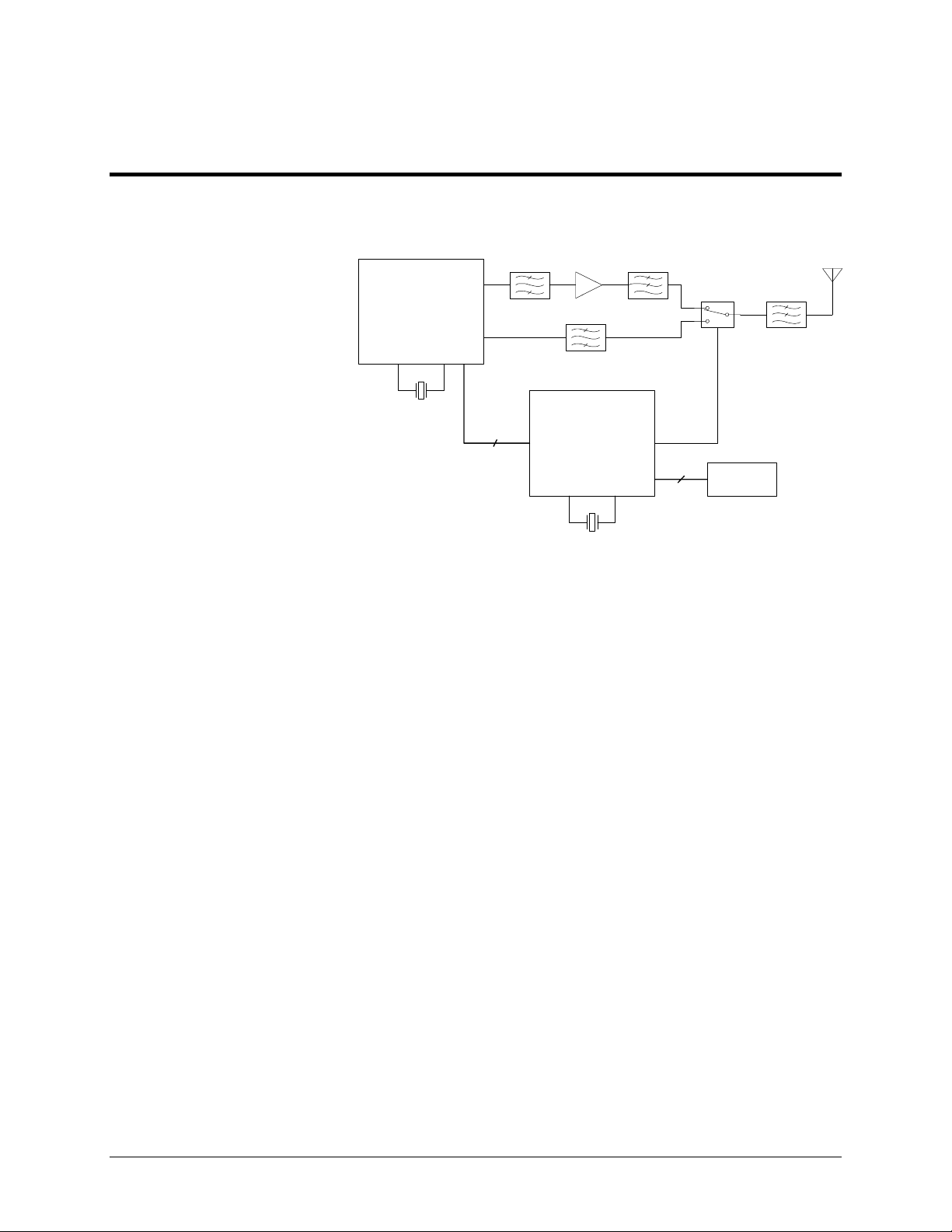
2.0 Functional Block Diagram
Bandpass
Filter
Transceiver
Intrgrated
Circuit
39.00 MHz
Crystal
10
Figure 1. Functional Block Diagram
Power
Amplifier
Bandpass
Filter
Microcontroller
32.768 kHz
Crystal
Lowpass
Filter
6
T/R
Switch
Host
Connector
Lowpass
Filter
6 ENC-900 Operating Manual: Chapter 1 Introduction
Page 11
2.1 Pin-out
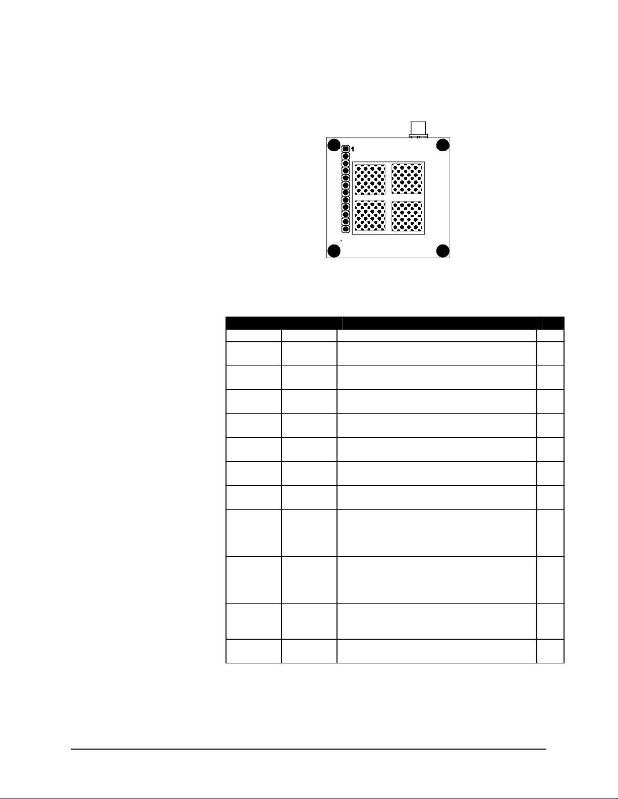
Figure 2 provides a top-view pin-out drawing of the ENC-900 module.
Figure 2 – Pin-out (Top View)
Table 1. Pin Description
No. Pin Name Description I/O
1 GND Ground reference for logic, radio and I/O pins.
2 VCC Positive Supply for Radio Circuitry. See
Section 2.3 for DC Characteristics
3 TXD Serial Data Input. Active low (TTL Level)
input.
4 RXD Serial Data Output. Active low (TTL Level)
output.
5 DTR RS-232 Data Terminal Ready. Active low
(TTL level) input.
6 CTS RS-232 Clear to Send. Active low (TTL
level) output.
7 RTS RS-232 Request to Send. Active low (TTL
level) output.
8 DSR RS-232 Data Set Ready. Active low (TTL
level) output.
9 RSSI1 Receive Signal Strength Indicator 1. This
output is the first of the three RSSI indicators
to become active high as the signal strength
increases.
10 RSSI2 Receive Signal Strength Indicator 2. This
output is the second of the three RSSI
indicators to become active high as the signal
strength increases.
11 RSSI3 Receive Signal Strength Indicator 3. This
output is the third RSSI indicator to become
active high as the signal strength increases.
12 DCD RS-232 Data Carrier Detect. Active low (TTL
level) output.
I
O
I
O
I
O
O
O
O
O
ENC-900 Operating Manual: Chapter 2 Electrical/Physical 7
Page 12

2.2 Mounting Location
Mounting is accomplished via the 12 pin 0.1” header and 4 mounting
holds along the edge of the board.
In order to maintain compliance with the FCC modular certification it
is necessary to mount the module in such a way that user is never closer
than 20 cm to the antenna.
The manual for end users of the product must contain a warning about
the 20 cm separation as outlined in the beginning of this manual.
Additionally, the transceiver may not be co-located with any other
antenna or transmitter.
8 ENC-900 Operating Manual: Chapter 2 Initial Setup and Configuration
Page 13
2.3 Antennas and Cabling
This section describes the recommended procedure for installing
cabling and antennas for use with ENC-900 module.
2.3.1 Antennas
Compliance with FCC regulations may only be maintained using the
specified antennas and maximum output power cannot be exceeding 36
dBm EIRP.
See appendix A for a list of approved antennas that can be used
with the ENC-900 radio modem. All the antennas listed on the
appendix A can be purchased from Encom Wireless Data Solutions
Inc. If you require another type of antenna, please contact Encom
Wireless Data Solutions Inc. The ENC-900 cannot be used with any
antenna that does not appear in Appendix A.
2.3.2 Cabling
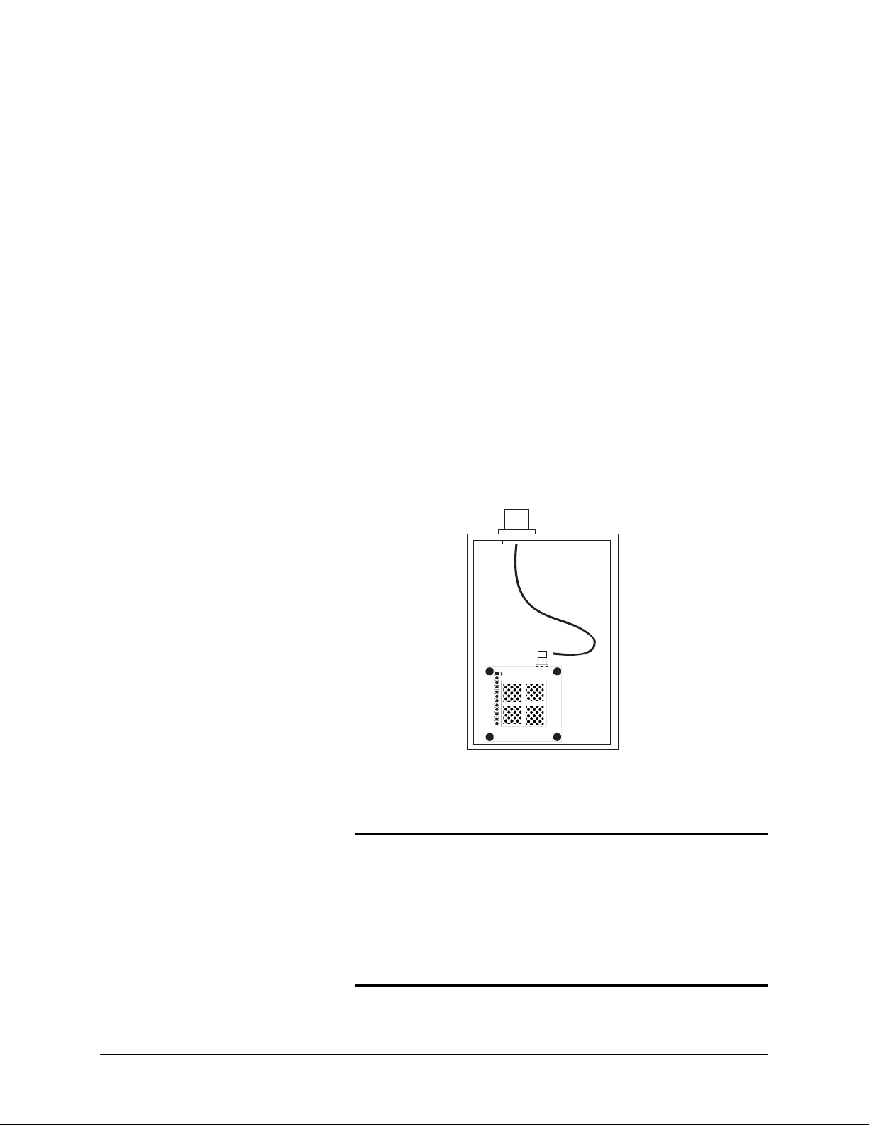
The most common method for installing the module is to run a short RF
Jumper cable from the module’s MCX connector to a reverse TNC
bulkhead connector on the chassis of the equipment as shown in the
following figure. These cables can be purchased from Encom Wireless
Data Solutions Inc.
Reverse TNC Connector
RG174 Cable
with MCX male
connector
and Reverse TNC
bulkhead
connector
MCX female connector
Cable losses are negligible for the short piece used within the chassis.
Additional losses up to 0.5 dB may be present in the MCX and Reverse
TNC connectors.
FCC Regulations allow up to 36dBm effective radiated power (ERP).
Therefore, the sum of the transmitted power (in dBm), the cabling loss and
the antenna gain cannot exceed 36dBm with respect to the isotropic
radiator.
ERP is calculated as follows:
ERP = Tx Power (dBm) – Cable/Connector Loss (dB) +Ant Gain (dBi)
Antenna Gain must be in dBi when calculating the 36dBm ERP limit.
1dBd = 2.15dBi
ENC-900 Operating Manual: Chapter 2 Electrical/Physical 9
Page 14

2.4 LED Operation
LED functionality is dependent on the mode of operation. Lines RX/SYNC,
TXMODE, and RSSI1,2 and 3 are designed to drive LED’s (active high).
Table 2 explains LED operation for the various modes.
MODE RSSI1,2,3
Power Up (S0=1) off
Power Up (S0=0) off
Command Mode off
Data Mode - Master RSSI mode based on all received packets
See Table 3
Data Mode - Repeater
During Sync.
Acquisition
Data Mode - Repeater
When Synchronized
Data Mode - Remote
During Sync.
Acquisition
Data Mode - Remote
When Synchronized
alternating 300ms ON
RSSI mode based on packets received from
Remotes*
See Table 3
alternating 300ms ON
RSSI mode based on packets received from the
Repeater or Master with which it
communicates
See Table 3
*If Remote have been silent for 2 seconds, repeater will base its RSSI on
packets received from the Master.
Table 2. LED Operation
10 ENC-900 Operating Manual: Chapter 2 Initial Setup and Configuration
Page 15

Signal strength, which is also reported in Register S123, is calculated based
on the last four valid received packets with correct CRC, and represented by
RSSI1, 2 and 3.
For Remotes, packets are received on every single hop either from a repeater,
or the master.
When calculating RSSI, the master takes into consideration all packets
received from Remotes and repeaters. Repeaters and Remotes only transmit
back to the master when they have information to send. Therefore, if no data
is coming back to the master then RSSI will never get updated at the master,
and the LED’s will be off.
Signal Strength
RSSI1 RSSI2 RSSI3
(dBm)
-95 50% duty cycle off off
-90 on solid off off
-85 on solid 50% duty cycle off
-80 on solid on solid off
-75 on solid on solid 50% duty cycle
-70 on solid on solid on solid
Table 3 - RSSI mode operation
ENC-900 Operating Manual: Chapter 2 Electrical/Physical 11
Page 16
IMPORTANT:
For best performance, it is
strongly recommended to use
a separate, linearly regulated
supply for Vcc Radio. Do
not directly feed a switching
power supply into Vcc
Radio.
Caution: Using any other power
supply which does not provide the
proper voltage or current could
damage the ENC-900 module.
2.5 DC Characteristics
Characteristic Min Typ Max Units
Supply Voltage 3.80 V
Transmit Current at 1W 900 mA
Receive Current 28 mA
Sleep Current 1 mA
12 ENC-900 Operating Manual: Chapter 2 Initial Setup and Configuration
Page 17

ENC-900 Operating Manual: Chapter 2 Electrical/Physical 13
Page 18

Refer to Appendix A for a
summary of the modem
commands
Configuration options are not
stored in non-volatile
memory until the WRITE
command (&W) is executed
3. MODES OF OPERATION
The ENC-900 modem can be easily configured to meet a wide range of
needs and applications. The module is designed such that all communication
is through one serial port. This port has two functions:
It provides the asynchronous interface with the host equipment for data that
is sent/received on the RF channel. When operating in this fashion, the
module is said to be in data mode.
It is also used for configuring and programming the module. When
operating in this fashion, the module is said to be in command mode.
In addition to data mode and command mode, there is a third mode of
operation called diagnostics mode. The module will always be in one of
these three modes.
3.1 Data Mode
Data mode is the normal operating mode of the ENC-900. When in data
mode, the ENC-900 is communicating with other ENC-900 modules, and
facilitating wireless asynchronous serial communication amongst two or
more terminal devices. There are three basic elements to any ENC-900
communications network:
• One module configured as the Master
• Zero or more modules configured as Repeaters
• One or more modules configured as Remotes
The function of the Master is to provide synchronization for the entire
network, and to control the flow of data. There is always one Master per
network. The Master is the ultimate destination for all data collected at the
various Repeater’s and Remote’s serial ports. With the network set up for
Point-to-Multipoint communication, all data received at the Master’s serial
port is transmitted to every Repeater and Remote in the network. The ENC900 is a frequency hopping transceiver, meaning that it “hops” to a new
frequency after a predetermined time interval. This time interval is a fixed
time set by the user, and can range from 8ms to 200ms. The ENC-900 hops
according to a pseudorandom pattern of 50 different channels.
When configured as a Remote, the ENC-900 searches for synchronization
with a Master. Network topologies consisting of a single Master and
virtually any combination of Remotes and Repeaters may be deployed. The
functionality of any particular ENC-900 can be configured as follows:
14 ENC-900 Operating Manual: Chapter 3 Configuration Options
Page 19

M
Network 1
MSRM
Network 2
S
M
Network 3
M
S
Network 4
Master Point-to-Point: The modem is configured to communicate
with a single Remote, either directly, or through one or more
Repeaters.
Master Point-to-Multipoint: The modem is configured to
communicate with one or more Remotes and/or Repeaters.
S
Remote: The modem is configured to communicate with one
Master either directly or through one or more Repeaters..
Repeater: The modem is configured to pass information from
either a Master or another Repeater onto subsequent Repeaters
and/or Remotes and vice versa. The Repeater also acts as a Remote
in the sense that, like a Remote, it passes information to/from its
SR
serial port.
Examples of different network topologies are shown in Figure 4. Network 1
shows Point-to-Point communication between a Master and Remote.
Network 2 makes use of a Repeater to communicate with the Remote.
Network 3 illustrates a simple Point-to-Multipoint network with no
Repeaters. Networks 4 and 5 gives examples of Point-to-Multipoint
networks consisting of both Repeaters and Remotes. There is effectively no
restriction to the number of Repeaters and Remotes that can be added to a
S
S
network. As seen in Network 4, a Master can communicate directly with
both Remotes and Repeaters.
3.2 Command Mode
The ENC-900 firmware has been designed to allow the user to customize the
operation of the modem through an AT Command Interface. This interface
is ideal for direct interface with another microcontroller or for higher level
Windows-based software applications, but also contains user-friendly built-in
register descriptions. These descriptions make it easy for the user to
S
configure the unit by manually inputting AT Commands and modifying SRegister parameters, using any standard terminal program. The ENC-series
R
development board is a useful tool for familiarizing yourself with the various
operating parameters and user interface. Reference schematics for the
S
development board can be found in the development kit user’s manual. To
access the ENC-900’s command mode using the development board:
1. Insert the module into the socket with the antenna connector at the
end near the power jack.
SR
2. Attach the supplied antenna.
3. Connect a straight through serial cable between the DB9 connector
and the serial port on your PC
MR
S
Network 5
Figure 4 - Sample Network
Topologies. Virtually any
Combination of Remotes and
Repeaters May be Used.
4. Run any terminal application program such as Hyperterminal
5. Set the serial port to 9600 baud, 8N1
6. Apply power to the development board
7. While the three RSSI LED’s are blinking, type ‘ENC’ (you have
about 5 seconds to do this). The modem should respond with ‘OK’.
8. Type ‘AT&V <ENTER>’
ENC-900 Operating Manual: Chapter 3 Configuration Options 15
Page 20

3.2.1 AT Command Interface
At this point you should see a menu similar to the following appear:
BAUD = 9600
E1 Q0 V1 W0
DCD &C1 DTR &D0 Framing &E0 Handshaking &K3 DSR &S1
S0=1 S2=43 S3=13 S4=10 S5=8
Operating Mode S101=1 Serial Baud Rate S102=7
Wireless Link Rate S103=2 Network Address S104=1
Unit Address S105=1 Hop Pattern S106=0
Encryption Key S107=1 Output Power S108=2
Hop Interval S109=4 Data Format S110=1
Packet Min Size S111=1 Packet Max Size S112=43
Packet Retransmissions S113=1 Quick enter to command S119=1
Packet Repeat Interval S115=1 Character Timeout, ms S116=8
RTS/DCD Framing, ms S120=0 DCD Timeout, ms S121=0
Secondary Hop Pattern S206=2 Packet Retry Limit S213=2
Average RSSI value S123= -0 dBm Buffer Mode S117=0
Roaming S118=0 Packet Size Control S114=0
Remote Control S122=0
OK
The ENC-900 is controlled through an AT Command line interface using a
command set which is very similar to a traditional Hayes telephone modem
command set.
All line entries must be preceded by the characters ‘AT’. The characters
‘AT’ are known as the attention characters and must be typed at the
beginning of each command line. For example, to change the operating
mode, type:
ATS101=2 <ENTER>
The modem should respond with ’OK.’ The above command will set the
operating mode to Master Point-to-Point.
Register settings are not immediately stored to non-volatile memory,
therefore if the modem is powered down at this point, the Operating Mode
would revert to its previous value. To store any recently updated command
registers, the following “write” command must be entered.
AT&W <ENTER>
3.3 Switching Between Command and Data Modes
Your modem must be in command mode for it to execute a command. If you
send characters when the modem is in data mode, the modem transmits the
characters over the air.
Depending on its settings, the modem will either power up in command
mode or data mode. Normally, when first received from the factory, the unit
will power up into data mode. During the first five seconds after power-up,
the user is given the opportunity to avoid entering into data mode but instead
enter into command mode by typing ‘enc’.
16 ENC-900 Operating Manual: Chapter 3 Configuration Options
Page 21
DATA
)
MODE
d
n
a
m
m
o
C
O
T
A
r
o
A
T
A
(
COMMAND
e
c
n
r
e
o
u
q
R
e
T
S
D
e
p
a
c
s
E
USER TYPES 'mhx'
MODE
Figure 5A. S0=1, S119=1
(factory default)
5 sec elapses
or
characters
other than
'mhx'
entered by
the user
POWER-UP
SEQUENCE
The terminal must be set for 9600 baud 8N1 in order for the modem to
accept these characters. If ‘enc’ is typed incorrectly, the modem will
immediately enter into data mode. If the five seconds elapses without any
response from the user, the modem will go into data mode.
In command mode, the module “autobauds,” meaning that it will adapt to the
baud rate of the DTE equipment to which it is connected. Therefore, when in
command mode, you may change the baud rate of your equipment, and the
ENC-900 will automatically adjust to this baud rate once an AT string is
issued. The new baud rate is stored in register S102. Several baud rates
ranging from 1200 to 115200 may be selected.
You can place the modem into Data Mode from Command Mode either by:
• Issuing the answer command (ATA <ENTER>); or,
DATA
)
MODE
d
n
a
m
m
o
C
O
T
A
r
o
A
T
A
(
e
c
n
r
e
o
u
q
R
e
T
S
D
e
p
a
c
s
E
COMMAND
MODE
Figure 5B. S0=1, S119=0
DATA
)
MODE
d
n
a
m
m
o
C
O
e
T
c
A
n
r
r
e
o
o
u
q
R
A
e
T
T
S
D
A
e
(
p
a
c
s
E
COMMAND
MODE
Figure 5C. S0=0
The escape sequence will not
be accepted unless both the
ENC-900 and the terminal
are set to the same baud rate
POWER-UP
SEQUENCE
500 msec
POWER-UP
SEQUENCE
500 msec
• Issuing the online command (ATO <ENTER>).
With traditional telephone line modems, these two commands serve different
purposes, however, with the ENC-900, these commands are identical. The
modem will now attempt to communicate with other ENC-900 modules.
While in Data Mode, the modem will communicate through the serial port at
the same baud rate as was last used in Command Mode
2
.
To return to Command Mode, you can either:
• Send the escape sequence. (The escape sequence consists of 1
second of inactivity, followed by the characters ‘+++’ followed by
another second of inactivity.); or,
• Toggle the DTR line (depending on the &D parameter).
The escape sequence must be issued at the baud rate that the modem has
been set to. If the modem is set to 19200 baud, and the escape sequence is
issued at 9600 baud, for example, the modem will not recognize it, and will
not go into Command Mode.
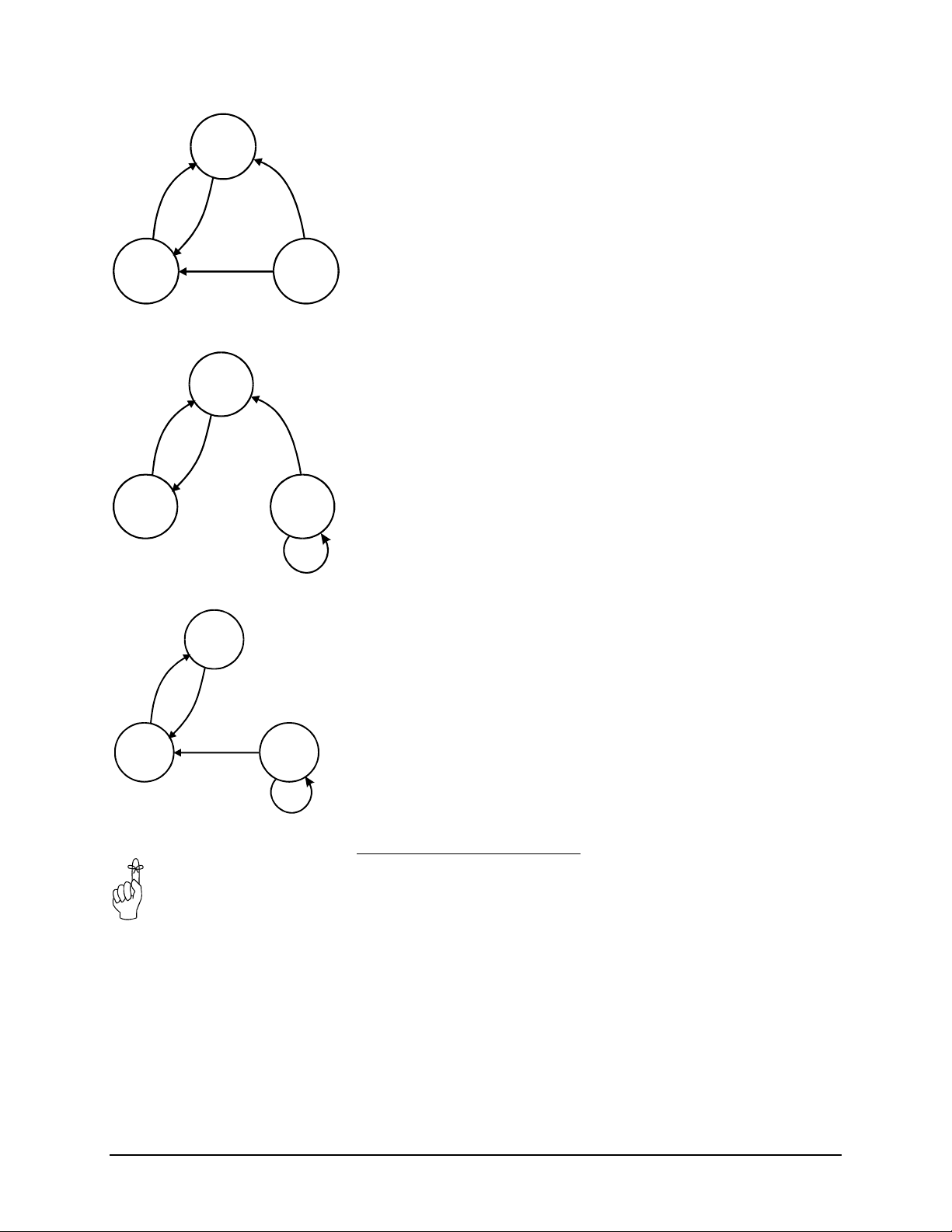
Figure 5 provides a state diagram for power-up, command mode, and data
mode. Note that there are three different variants of the state diagram which
depend on the values of registers S0 and S119. See the appropriate sections
for more details about these registers. The factory defaults are S0=1 and
S119=1.
2
It is possible to enter into Data Mode at a different baud rate from what is
currently being used in Command Mode by issuing the command
ATS102=x, where x is one of the valid baud rates. Care must be taken when
setting the baud rate in this manner. If you issue another AT string after
attempting to set the baud rate using ATS102 <ENTER>, the modem will
again autobaud and automatically revert to the baud rate of the host
equipment. For example, if your equipment is running at 9600 baud and you
wish to set up the modem to run at 19200 baud, the following command line
entry would be suitable:
ATS102=5&WA <ENTER>
The first part (S102=5) sets the baud rate to 19200. The next characters
(&W) write this baud rate to memory. The last character (A) puts the
modem into Data Mode. Once in Data Mode, the modem is unable to
autobaud, and is fixed at 19200 baud. By combining several commands into
one command line entry, and then immediately putting the modem online,
the modem is not given a chance to autobaud back to 9600.
ENC-900 Operating Manual: Chapter 3 Configuration Options 17
Page 22

4. CONFIGURATION
Warning: After testing the units
for correct operation using the
quick-start approach, be sure to
modify some of the security
parameters such as Network
Address and Encryption Key, to
avoid unintentional
communication with other users of
ENC-900 products..
This chapter provides a detailed description of the various operating
parameters of the ENC-900. Section 4.1 provides a quick-start approach
which outlines the minimum requirements for establishing communication
between two ENC-900 modules. The settings will not necessarily provide
optimal performance for your application, but will verify that the modules
are functioning correctly.
Section 4.2 describes the AT Command interface, and the various AT
Commands. Section 4.3 covers all S-Register parameters which affect the
operation of the modem, and Section 4.4 provides a description of all
diagnostic features of the modem.
4.1 Quick Start Approach
There are several parameters that must be set in order to establish
communication between a pair of ENC-900 modules.
The ENC-900 is equipped with four standard factory default settings.
Instead of manually configuring each individual operating parameter, a
global command may be used to quickly configure the modem for a
particular type of operation. For example, to quickly implement Network 1,
Factory default 1 would be applied to the Master, and Factory default 2
would be applied to the Remote. To quickly set up Network 2, apply Factory
1 to the Master, Factory 3 to the Repeater, and Factory 4 to the Remote.
These defaults will get you started and only ensure that a link can be
established, but do not necessarily provide the best performance.
Optimization of the communications link is discussed in later sections.
To implement the basic network illustrated in Figure 6, Network 1,
M
S
Network 1
MSRM
Network 2
Figure 6. Basic Networks
1. Insert the module into the development board socket with the
antenna connector at the end near the power jack.
2. Attach the supplied antenna.
3. Connect a straight through serial cable between the DB9 connector
and the serial port on your PC
4. Run any terminal application program such as Hyperterminal and
set the terminal application’s serial port settings to 9600 baud, 8N1
5. Apply power to the development board
6. While the three RSSI LED’s are blinking, type ‘ENC’ (you have
about 5 seconds to do this). The modem should respond with ‘OK’.
SR
7. Configure the unit to Factory Setting 1 by typing AT&F1 <return>. This
puts the unit into Master Point-to-point mode.
8. Store these settings to memory by typing AT&W <return>.
9. Put the modem into Data Mode by typing ATA (or ATO) <return>
10. Perform above steps for the second unit, using Factory Setting 2 instead of
Factory Setting 1. This will configure the second unit as a Remote.
18 ENC-900 Operating Manual: Chapter 3 Configuration Options
Page 23

The units should now be communicating. Remember, the parameters defined
by Factory Settings 1 and 2 will likely not be the most ideal for your
application, but will quickly allow you to test the units. A complete
summary of the settings defined by all four factory settings can be found in
Appendix D. Factory Default Settings.
Settings are not immediately stored in non-volatile memory, therefore, the
command &W is issued to store the current configuration into non-volatile
memory. Settings are retained even after powering down. All user
selectable parameters for the ENC-900 are described in detail in Sections 4.2
and 4.3:
The escape sequence will not
be accepted unless both the
ENC-900 and the terminal
are set to the same baud rate
4.1.1 Checking the Link
To check if the units are communicating, observe the LED indicators on the
development board which houses the Remote unit. If the link is good, up to
three RSSI LEDs on the Remote modem should be active along with the
RX/Sync LED, and if the link is absent (due to a fault at one end or another,
such as misconfiguration), the LED’s will be in either “scanning mode” or
inactive. See Section 2.2 for complete LED operation.
Characters typed at the Master terminal should appear at the Remote’s
terminal, and vice versa. Also, verify that the RX LED blinks as packets of
data are received at the Master modem. As data is sent from Remote to
Master, the RX indicator should blink on as correct packets of data are
received. At this point, the Master’s RSSI LED’s should become active. It
is recommended that if the ENC-900 will be deployed in the field where
large distances separate the units, the modems should be configured and
tested in close proximity (e.g., in the same room) first to ensure a good link
can be established and settings are correct. This will facilitate
troubleshooting, should problems arise.
4.2 AT Commands
Several AT Commands are supported by the ENC-900. These commands
affect the operation of the modem in command mode and the transition
between data and command modes. More commands and S-Register settings
are discussed in Sections 4.3 and 4.4.
To make the command line more readable, you can insert as many spaces as
desired. The command line holds up to 16 characters, not including the AT
prefix. If you want to send more than one command line, wait for a response
before entering the AT prefix at the start of the next command line. To reexecute the previous command, enter A/. The modem will execute the
previous command line.
When in Command Mode, the modem “autobauds”, meaning that it will
automatically adjust to the baud rate of the terminal. You may change the
terminal baud rate while in Command Mode without losing communication
with the modem.
For the AT command protocol, an escape sequence consists of three
consecutive escape codes preceded and followed by at least 1 second of
inactivity. Typically, the ‘+’ character is used as the escape code.
+++ preceded and followed by 1 second of inactivity
ENC-900 Operating Manual: Chapter 4 Configuration 19
Page 24

Note that the terminal must be configured to the same baud rate as the
modem in order for the modem to recognize the escape sequence. The
modem is unable to “autobaud” while in Data Mode.
The following is a description of all available commands. ‘*’ denotes
standard factory settings. All of the following commands must be preceded
by “AT”.
A Answer
The A command puts the modem into data mode, where the modem
attempts to communicate with other compatibly configured modems
(Type ATA <return>).
Dxxxxx, DTxxxxx, DPxxxxx Dial
The D, DT or DP are identical commands which change the unit
address to xxxxx and puts the modem into data mode (Type
ATDxxxxx <return>).
E Command Echo
Your modem is preset to return (or echo) commands to the host
microprocessor when in Command Mode.
E0 No Command Echo
*E1 Command Echo
I Identification
The I command returns various modem information settings.
I0= String up to 15 characters stored in non-volatile memory
I1 Product Code
I2 Self Test Result
I3 Product Identification (Firmware Version)
I4 Firmware Date
I5 Firmware Copyright
I6 Firmware Time
I7 Serial Number
O On-line Mode
The O command puts the modem into data mode. This command is
identical to the A command.
Q Quiet Mode
Your modem is preset to send responses when it executes
commands, and there after to keep the host informed of its status.
*Q0 Enable modem responses
Q1 Disable modem responses
V Result Codes display
Your modem can either display result codes as words or numbers.
V0 Display Result Codes as numbers
*V1 Display Result Codes as words
20 ENC-900 Operating Manual: Chapter 4 Configuration
Page 25

Refer to Appendix A (page
49) for a summary of the
modem commands
W Connection Result
This parameter determines the modem response at the transition to
Data Mode from Command Mode
*W0 Reports computer (DTE) baud rate as CONNECT xxxx
W1 Reports wireless rate between modems as CARRIER
xxxx.
Z Reset and load stored configuration
The Z command resets the modem and loads the stored
configuration.
&C DCD (Data Carrier Detect)
The &C command controls the modem’s DCD output signal to the
host microprocessor. This command determines when the DCD is
active.
&C0 DCD is always ON
*&C1 DCD on when modems are synchronized. DCD is always
on when unit is configured as Master.
&C2 DCD used for output data framing
&C3 DCD is always ON, but S120 & S121 timing is still valid
&F1
Master Slave
&F1
Master
&F2
&F3
Repeater
&D DTR (Data Terminal Ready)
The &D command controls what action the modem performs when
the DTR input line is toggled. The DTR input is controlled by the
&F4
Slave
host microprocessor.
*&D0 DTR line is ignored
&D1 Not Supported
&D2 De-assert DTR to force the modem into command mode
from data mode. DTR must be asserted before putting the
modem back into data mode (The modem is put back into
data mode in the normal manner using ATA or ATO)
&D3 De-asserting DTR disconnects and resets modem. Modem
will remain in this state until DTR again goes active.
&F Load Factory Default Configuration
The &F command resets the modem and loads the default factory
configuration.
&F1 Master Point-to-Multipoint. Designed to communicate
with modems configured as &F2 or &F3.
&F2 Remote. Designed to communicate with another modem
configured as &F1.
&F3 Repeater. Designed to communicate with modems
configured as &F1 and &F4.
&F4 Remote working with factory default Repeater and factory
default Master. Communicates directly with Repeater
configured as &F3.
ENC-900 Operating Manual: Chapter 4 Configuration 21
Page 26

&K Handshaking
The &K command controls the handshaking between the modem
and host microprocessor.
&K0 Disable handshaking
&K2 RTS/CTS input data framing.
*&K3 Enable hardware handshaking (RTS/CTS)
Configuration options are not
stored in non-volatile
memory until the WRITE
command (&W) is executed
&S DSR (Data Set Ready)
The &S command controls the DSR line for the modem, and
determines when it is active
&S0 DSR is always ON
*&S1 DSR is ON in Data Mode, OFF in Command Mode
&V View Configuration
The &V command displays all S registers and their current values.
&E Framing Error Check
This command enables or disables Framing Error Check. When
enabled, the modem looks for the stop bit. If the stop bit is absent,
the byte is thrown out. When enabled, the modem also does a parity
check. Note that the data format (number of data bits, parity type,
and number of stop bits) is defined by S register 110.
*&E0 Disable Framing Error Check
&E1 Enable Framing Error Check
&W Write Configuration to Memory
The &W command stores the active configuration into the modem’s
non-volatile memory.
Sxxx? Read S register value
This command causes the modem to display the current setting of S
register xxx.
Sxxx=yyy Set S register value
This command sets the specified S register to a value specified by
yyy.
AT Command Result Codes
The ENC-900 module can display the results of a command as
either text strings or numerical data. The following chart shows
resulting text string and corresponding numeric result.
0 OK
3 NO CARRIER
4 ERROR
22 ENC-900 Operating Manual: Chapter 4 Configuration
Page 27

4.3 S Registers
Refer to Appendix A for a
summary of the S-Registers.
S Registers 2 cannot be
stored to non-volatile
memory.
The S Registers described in this section affect the operating characteristics
of the modem.
S Register 0 - Auto Answer
If this register is set to zero, the modem will power up in command mode. If
this register is set to one, the modem will power up in data mode.
S Register 2 - Escape Code
This register contains the ASCII value of the escape character.
The default value (decimal 43) is equivalent to the ASCII character ‘+’.
Values greater than 127 disable the escape feature and prevent you from
returning to the Command Mode. This register cannot be stored to nonvolatile memory. If the modem is reset, or powered down, the default value
is restored.
Default is ‘+’ (decimal 43).
ENC-900 Operating Manual: Chapter 4 Configuration 23
Page 28

S Register 101 - Operating Mode
Only one Master can exist
for each network.
The Operating Mode (register S101) partly defines the “personality” of the
ENC-900 module. Allowable settings for this register are 1 through 6 as
follows:.
• S101=1 Master Point to Multipoint
• S101=2 Peer-to-Peer Mode
• S101=3 Remote
• S101=4 Repeater
• S101=5 Master - Diagnostics
The default for this register depends on which factory default is selected as
shown below:
• Default for Factory Setting &F1 is 1 (Master Point-to-Multipoint)
• Default for Factory Setting &F2 is 3 (Remote)
• Default for Factory Setting &F3 is 4 (Repeater)
• Default for Factory Setting &F4 is 3 (Remote)
1) Master - Point to Multipoint. In any given network,
there is always only one Master. All other units should be configured as
either Remotes or Repeaters. When defined as a Point-to-Multipoint
Master, the modem broadcasts data to all Remotes and Repeaters in the
network, and is also the ultimate destination for data transmitted by all
Remotes and Repeaters. In addition, the Master defines the following
network parameters to be utilized by all other modems in the network (See
the appropriate sections for a complete description of these parameters):
Maximum Packet Size (S112)
Minimum Packet Size (S111)
Wireless Link Rate (S103)
Hop Interval (S109)
2) Master – Point to Point. This mode of operation provides
for communication between the master and a single repeater or Remote.
The master will communicate only with the Remote or repeater which
shares a common unit address with the master. For example, if a Remote
has been assigned Unit Address 100, and the Master wishes to communicate
with that Remote, the Master’s unit address must also be set to 100. If there
are Repeaters in the network, they will pass the packet through to the
Remote, and vice versa. Because Repeaters also have Remote functionality
(i.e., a Repeater can be connected to a terminal), the Master can choose to
communicate solely with a Repeater. This would be accomplished by
assigning the same Unit Address to both the Master and the Repeater.
24 ENC-900 Operating Manual: Chapter 4 Configuration
Page 29
3) Remote. Up to 255 Remotes may exist in a network, all of which
communicate with the common Master (either directly or via Repeater(s)).
Remotes cannot directly communicate with other. Remotes only provide
acknowledgement for packets of data sent by the Master when the Master is
in Point-to-Point mode. In multipoint mode, multiple Remotes would
conflict with one another if they were all trying to acknowledge the Master
at the same time. The Master does, however, send acknowledgements to all
messages it receives from Remotes. The Master initiates communications
by sending a broadcast message to all Remotes. Each Remote can choose
one of several windows in which to transmit. If there happens to be two
Remotes attempting to talk at the same time, the Master may not receive the
data, and the Remotes therefore would not get an acknowledgement. At
this point, the Remotes would attempt to get the information through at
random time intervals, thus attempting to avoid any more conflicts. Special
parameters which control the Remote’s response characteristics can be
modified with S Registers S115 and S213.
Network 50
Hop Pattern 2
PHP=1
Master
Hop Pattern 1
PHP=1
SHP=2
Repeater
PHP=2
Slave
Figure 7 - Repeater
Operation
Hop Pattern 3
Repeater
PHP=2
SHP=3
Master Repeater
PHP=1
HopPatt er n 1
PHP=1
SHP=2
Hop Pattern 2
Slave
PHP=2
Figure 8 - A Network
Utilizing Three Hopping
Patterns
If there is no DTE connected
to the Repeater, turn off
handshaking (&K0) and set
the baud rate to 115K.
Slave
PHP=3
4) Repeater. A more precise title would be Repeater/Remote, because
a Repeater also has much of the same functionality as a Remote. A terminal
can be connected at the Repeater location and communicate with the Master
terminal. There is no restriction to the number of Repeaters in a network,
allowing for communication over virtually limitless distances. The
presence of one Repeater in a network automatically degrades system
throughput by half. Additional Repeaters, regardless of the quantity, do not
diminish system throughput any further. To understand Repeater operation,
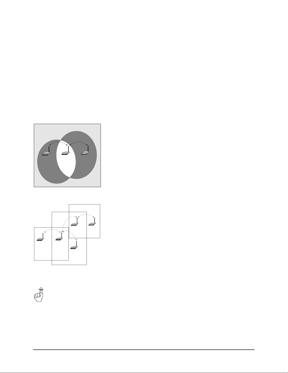
consider the module as belonging to two hopping patterns at the same time:
The Primary Hopping Pattern and the Secondary Hopping Pattern. In
Figure 7, the Master belongs to Hopping Pattern 1, and communicates with
the Repeater on this hopping pattern. The Remote belongs to Hopping
Pattern 2, and communicates with the Repeater on this hopping pattern.
The whole system belongs to Network 50 (i.e., all units must be assigned
the same Network Address (S104), which in this case was selected to be 50.
Note that Remotes and Master only communicate on their respective
Primary Hopping Pattern. Repeaters communicate on the Primary Hopping
Pattern when communicating with the Master (or with another Repeater
between itself and the Master). Repeaters communicate on their Secondary
Hopping Pattern when communicating with Remotes (or with another
Repeater between itself and the Remotes). Figure 8 shows another
example.
If the Repeater is not also being used as a Remote (there is no DTE
connected to the serial port), it is recommended that the Repeater’s baud
rate be set to 115K, and that handshaking be disabled (&K0). This will help
ensure a smooth flow of data through the network.
ENC-900 Operating Manual: Chapter 4 Configuration 25
Page 30

S Register 102 - Serial Baud Rate
The Serial Baud Rate is the current speed that the modem is using to
communicate with the DTE. In command mode, the module “autobauds,”
meaning that it will adapt to the baud rate of the DTE equipment to which it
is connected. Therefore, when in command mode, you may change the
baud rate of your equipment, and the ENC-900 will automatically adjust to
this baud rate once an AT string is issued. The new baud rate is stored in
register S102. If you issue a command to change the value of S102, the
instant you issue another command, the baud rate will revert back to that of
the DTE equipment. Therefore, it is advisable to operate in Command Mode
at the desired baud rate for Data Mode.
The possible values are:
1 115200
2 57600
3 38400
4 28800
5 19200
6 14400
*7 9600
8 7200
9 4800
10 3600
11 2400
12 1200
It is generally advisable to choose the highest rate that your terminal
equipment will handle to maximize performance, unless a limitation on the
available bandwidth is desired. If the DTE is a personal computer, the port
can usually be used reliably at 115200. Issuing the &Fx command (factory
default) does not affect the current setting of S102.
The Master determines the
Wireless Link Rate. This
setting on all other modems
is ignored..
S Register 103 - Wireless Link Rate
The Wireless Link Rate is the optimization method for which modems will
communicate over the RF link. It is only necessary to set this parameter on
the Master unit. Units configured as Repeaters and Remotes will ignore this
setting, and adjust automatically to the rate of the Master.
The allowable settings are:
*2 Fast without Forward Error Correction
4 Fast with Forward Error Correction
Depending on the application requirements, each mode will provide
different throughput and performance.
In general, Forward Error Correction (FEC) reduces throughput, but in
some environments will actually increase throughput. FEC can reduce the
number of bad data packets, and hence reduce the need to retransmit.
26 ENC-900 Operating Manual: Chapter 4 Configuration
Page 31

Select a Network Address
and assign it to all units
which will be included in the
network.
Warning: Encom Wireless
strongly recommends changing the
Network Address to a value
different from the factory default
before deploying the network.
S Register 104 - Network Address
The Network Address defines the membership to which individual units can
be a part of. By establishing a network under a common Network Address,
the network can be isolated from any other concurrently operating network.
As well, the Network Address provides a measure of privacy and security.
Only those units which are members of the network will participate in the
communications interchange. Valid values for the Network Address range
from 0 to 255, inclusive.
To enhance privacy and reliability of communications where multiple
networks may operate concurrently in close proximity, it is suggested that a
typical value be chosen – perhaps something meaningful yet not easily
selected by chance or coincidence.
Default is 1.
S Register 105 - Unit Address
Use the same Unit Address
on both units for point-topoint mode. In multipoint
mode, set each Remote and
Repeater to a different Unit
Address.
Valid Unit Addresses are 1
to 65535.
In point-to-point operation, the Unit Address on both the Master and
Remote (or Repeater) units must be the same. In a multipoint system, the
Unit Address uniquely identifies each Remote and Repeater from one
another. Each unit in a multipoint system must have a unique Unit Address
ranging from 0 to 255.
S Register 106 - Primary Hopping Pattern
S Register 206 - Secondary Hopping Pattern
Since the ENC-900 is a frequency-hopping modem, the carrier frequency
changes periodically according to one of 64 pseudo-random patterns,
defined by the Primary and Secondary Hopping Patterns. Valid entries for
each are 0 through 63.
The concept of Primary and Secondary Hopping Patterns was introduced in
the discussion of S Register 101 (Operating Mode).
Using the designations M[a,] Rx[a,b] and Sx[a] where:
- M indicates Master;
- R indicates Repeater;
- S indicates Remote;
- x is the Unit Address;
- a is the primary hopping pattern; and,
- b is the secondary hopping pattern;
ENC-900 Operating Manual: Chapter 4 Configuration 27
Page 32
Master Slave
Master
Repeate r
Master
Repeater1
Slave
Repeater2
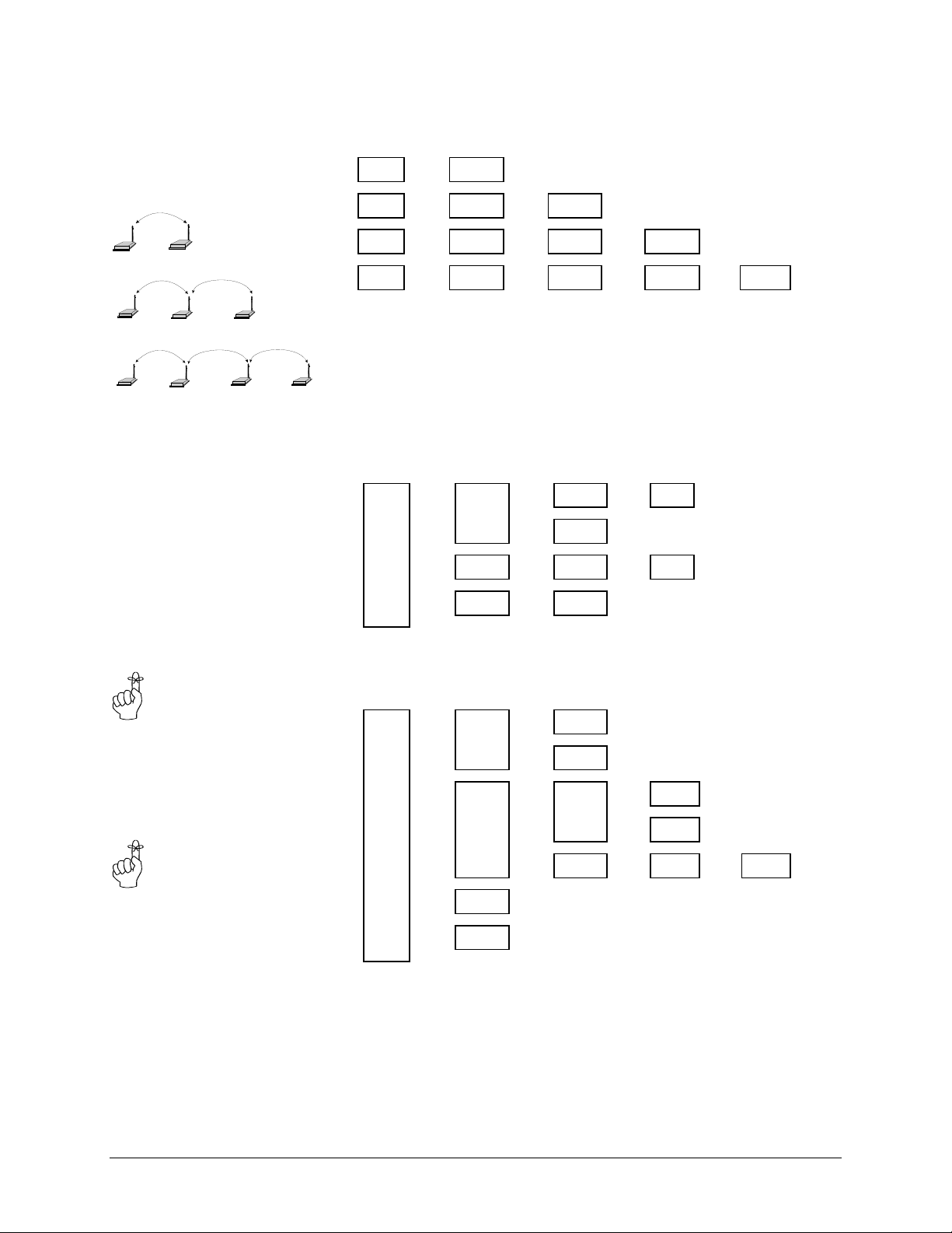
the following diagrams illustrate the methodology for deploying simple to
complicated networks:
M[1]
←→
M[1]
←→
M[1]
←→
M[1]
←→
It is reasonable to consider a Repeater as being both a Remote and a Master,
S1[1]
R1[1,2]
R1[1,2]
R1[1,2]
←→
←→
←→
S2[2]
R2[2,3]
R2[2,3]
←→
←→
S3[3]
R3[3,4]
←→
S4[4]
alternating between Primary and Secondary Hopping Patterns as the unit
changes channel. Consider R1 in the illustration below. When
Slave
communicating with the Master, R1 is acting like a Remote on Primary
Hopping Pattern 1. When communicating with R2 and S4, R1 is acting like
a Master on Secondary Hopping Pattern 2. If multiple Repeaters are used,
they should have different Secondary Hopping Patterns:
M[1]
←→
←→
←→
R1[1,2]
R5[1,3]
R8[1,4]
R2[2,5]
←→
S4[2]
←→
R6[3,6]
←→
S9[4]
←→
S3[5]
←→
S7[6]
←→
Remotes and Masters do not
use Secondary Hopping
Patterns
Remember to assign a
unique Unit Address (1 to
65535) to each unit in the
system
Note that all units have a unique Unit Address.
Networks of any complexity can be created by linking multiple Repeaters
and Remotes:
M[1] R4[1,3]
R1[1,2]
←→
←→
←→
←→
S11[1]
S12[1]
S2[2]
←→
S3[2]
←→
←→
←→
R5[3,6]
R8[3,7]
S6[6]
←→
S7[6]
←→
←→
R9[7,8]
S10[8]
←→
With a limitation of 64 hopping patterns, one might suspect that there is a
limitation to the number of repeaters in a system. However, if the units are
far enough away from one another, hopping patterns may be reused in
different sections of the network, without causing interference.
28 ENC-900 Operating Manual: Chapter 4 Configuration
Page 33

All units within a network
must use the same
encryption key.
Warning: Encom Wireless
strongly recommends changing the
Encryption Key to a value
different than the factory default
before deploying the network.
S Register 107 - Encryption Key
The Encryption Key provides a measure of security and privacy of
communications by rendering the transmitted data useless without the
correct key on the receiver. Valid Encryption Keys range from 0 to 255.
Keep in mind that all units within the network must use the same key for
communications to succeed.
S Register 108 - Output Power Level
Not all the power levels are available on all radio modules.
• Product code (ATI1): ENC-900L, will be factory limited to
transmit up to 100mW output power, and will ignore all the level 3
setting.
• Product code (ATI1): ENC-900, will accept the level 3 setting and
transmit up to 1W output power
The Output Power Level determines at what power the ENC-900 transmits.
The ENC-900’s sensitive receiver can operate with very low power levels,
so it is recommended that the lowest power necessary is used; using
excessive power contributes to unnecessary “RF pollution”.
The allowable settings are:
0 1 mW
1 10 mW
*2 100 mW
3 1000 mW (not available for ENC-900L model)
Ideally, you should test the communications performance between units
starting from a low power level and working upward until the RSSI is
sufficiently high and a reliable link is established. Although the conditions
will vary widely between applications, typical uses for some of the settings
are described below:
Power Use
1 mW For in-building use, typically provides a link up to 300 feet on the
same floor or up/down a level. Outdoors, distances of 10 km can
be achieved if high-gain (directional) antennas are placed high
above ground level and are in direct line-of-sight.
10 mW 200-500 ft indoors, 8-15 km* outdoors.
100 mW 400-800 ft indoors, 15-25 km* outdoors.
1000 mW Typically provides communications up to a distance of 1000 feet
or more in-building on the same floor or up/down a few levels,
depending on building construction (wood, concrete, steel, etc.).
In ideal line-of-sight conditions, up to 30 km* or more can be
achieved.
(If the antennas of directional gain greater than 6 dBi (≈3.85
dBd) are used, the peak power from the radio should be
reduced by the amount in dB that the directional gain of the
antenna exceeds 6 dBi (≈3.85dBd) (see next page for
maximum allowed output power calculation example)
• These outdoor distances assume antennas are mounted at least 100
ft above ground level.
ENC-900 Operating Manual: Chapter 4 Configuration 29
Page 34

The hopping interval is
controlled by the master.
The Remote and repeater
units will use the hopping
interval setting from the
master.
IMPORTANT:
FCC Regulations allow up to 36 dBi effective radiated power (ERP).
Therefore, the sum of the transmitted power (in dBm) and the antenna
gain cannot exceed 36 dBi.
1 mW = 0 dBm
10 mW = 10 dBm
100 mW = 20 dBm
1000 mW = 30 dBm
For example, when transmitting 1000 mW (30 dBm), the antenna gain
cannot exceed 36 - 30 = 6dBi (≈3.85dBd). If an antenna with a gain
higher than 6dBi (≈3.85dBd) were to be used, the power setting must be
adjusted appropriately. Violation of FCC regulations can result in
severe fines.
S Register 109 - Hopping Interval
This option determines the frequency at which the modems change channel.
Note that the Master controls this parameter for the entire network. This
setting is ignored in units configured as Remotes or Repeaters.
The allowable settings are:
*1 8 msec
2 12 msec
3 16 msec
4 20 msec
5 30 msec
6 45 msec
7 80 msec
8 120 msec
Some of the shorter hop intervals are incompatible in combination with:
30 ENC-900 Operating Manual: Chapter 4 Configuration
• repeaters in the system;
• the value set for link rate (S103); and,
• larger maximum packet sizes (S112).
See Appendix E for optimal Hopping Interval settings in relation to packet
size and link rate.
Page 35

S Register 110 - Data Format
This register determines the format of the data on the serial port. Allowable
settings are:
*1 8 bits, No Parity, 1 Stop
2 8 bits, No Parity, 2 Stop
3 8 bits, Even Parity, 1 Stop
4 8 bits, Odd Parity, 1 Stop
5 7 bits, No Parity, 1 Stop
6 7 bits, No Parity, 2 Stop
7 7 bits, Even Parity, 1 Stop
8 7 bits, Odd Parity, 1 Stop
9 7 bits, Even Parity, 2 Stop
10 7 bits, Odd Parity, 2 Stop
11 9 bits, No Parity, 1 Stop
S Register 111 - Packet Minimum Size
S Register 112 - Packet Maximum Size
S Register 116 - Packet Character Timeout
These settings determine the conditions under which the modem will
transmit accumulated data over the air.
S Register 111 - Minimum Size
Valid entries for this register are 1 to 255 bytes, which defines the minimum
number of bytes to receive from the DTE before encapsulating them in a
packet and transmitting over the air.
Note that if register S114=0 at any particular Repeater or Remote, that
Repeater or Remote will ignore its own S111 register and abide by the
Master’s S111 setting. If S114=1 at any particular Repeater or Remote, that
Repeater or Remote will use its own local S111 setting. The default for
S111 is 1 byte.
S Register 112 - Maximum Size
This setting has a range of 2 to 255, and defines the maximum number of
bytes from the DTE which should be encapsulated in a packet. This value
should be greater than the minimum packet size, but not smaller than is
necessary for reliable communications. If the wireless link is consistently
good and solid, a maximum size of 255 will yield the best throughput
(depending on the higher level protocols of the connected equipment).
However, if the link is poor (e.g., experiencing excessive interference) and
data is frequently retransmitted, the maximum packet size should be
reduced. This decreases the probability of errors within packets, and
reduces the amount of traffic in the event that retransmissions are required.
Note that if register S114=0 at any particular Repeater or Remote, that
Repeater or Remote will ignore its own S112 register and abide by the
Master’s S112 setting. If S114=1 at any particular Repeater or Remote, that
Repeater or Remote will use its own local S112 setting. The default for
S112 is 255 bytes.
ENC-900 Operating Manual: Chapter 4 Configuration 31
Page 36

S Register 116 - Packet Character Timeout
This register has valid entries of 0 to 254 milliseconds. The Packet
Character Timeout timer looks for gaps in the data being received from the
DTE. The timer is only activated after the Minimum Packet Size has been
accumulated in the modem. After which, if the timer detects a gap in the
data exceeding the Packet Character Timeout value, the modem will
transmit the data.
The ENC-900 will accumulate data in its buffers from the DTE until one of
the following requirements is met (whichever occurs first):
• The Maximum Packet Size (in bytes) has been accumulated;
• The Minimum Packet Size has been accumulated AND the Packet
Character Timeout interval has elapsed.
The default for the Packet Character Timeout is 5 ms. If set to 0 ms, the
unit will buffer exactly the minimum packet size before transmitting.
S Register 113 - Packet Retransmissions
This register applies to both Master and Repeater operation. It does not
apply to Remote operation. In point-to-multipoint mode, the Master will
retransmit each data packet exactly the number of times defined by the
Packet Retransmissions parameter. In point-to-point mode, the Master will
only retransmit the packet if it does not get an acknowledgement from the
Remote with which it is communicating. In this case, the Master will
continue to retransmit until an acknowledgement is received, or the
retransmission limit is reached. When the retransmission limit is reached,
the Master discards the packet. The Master retransmits once at the
beginning of each hopping interval until the limit is reached. This
parameter is not necessary in Remote units since all Remotes receive
acknowledgement from the Master, and needn’t blindly retransmit if it has
knowledge that the Master has received the packet.. As discussed
previously, the Repeater effectively behaves as both a Master and a Remote.
When the Repeater is tuned to its Secondary Hopping Pattern (acting as a
Master), the Packet Retransmissions Parameter comes into play. The
Repeater will re-send packets of data on to Remotes or other Repeaters
exactly the number of times defined by the Packet Retransmissions
parameter.
Recipients of the packet will discard any duplicates. The valid settings for
this parameter are 0 to 255 retransmissions. The default is 1.
S Register 114 - Sleep Mode
Depend on the level of setting; the radio will turn most of the internal
circuit off to save the power consumption. The allowable settings for this
register are:
*0 Disabled
1 Level 1- recommend to use in Point-to-Multipoint
protocol, radio will turn most of the internal
circuit off as well as skip certain hop to save
power.
2 Level 2 – recommend to use in Peer-to-Peer protocol,
radio will turn off all of the internal circuit
except the I/O and Serial Data Input Interrupt.
32 ENC-900 Operating Manual: Chapter 4 Configuration
Page 37

S Register 115 - Packet Repeat Interval
A parameter that is specific to Remotes and Repeaters is the Packet Repeat
Interval.
The allowable settings are 1 through 255. The default is 1.
This parameter defines a range of random numbers that the Remote will use
as the next slot in which it will attempt to send the packet. For example, if
this register is set to 7, the Remote will choose a number between one and
seven as the next slot in which to transmit. Suppose the random number
generator picks 5, then the Remote will transmit in the fifth time slot. A
Remote will transmit a maximum of once per hopping interval, however,
depending on the duration of the hopping interval and the maximum packet
size, more than one slot per hop is potentially available. The Remote will
transmit more frequently when a Repeat Interval with a smaller range is
selected. Choose 1 to have the Remote transmit in the first available slot.
Choose higher intervals for less frequent transmission, or to avoid collisions
between many Remotes in the system.
This register is always disregarded and taken as S115=1 in Point-to-Point
mode.
S Register 117 - Radio Buffer Mode
Radio Buffer Mode controls the ENC-900 TX buffer behaviors.
The allowable settings for this register are:
*0 High Throughput Mode
1 Quick Turn-Around Mode
S Register 118 - Roaming
This mode is activated on Remotes and repeaters by setting register
S118=1. In this mode, a Remote/repeater looks for synchronization with a
Master having the same network address and encryption key, but without
regard for the hopping pattern S106. Once the Remote/repeater finds such a
master, it tunes to that master’s hopping pattern. If synchronization is lost,
the Remote/repeater will again begin searching for a new master. Using
this algorithm, a mobile unit can ‘roam’ and automatically synchronize with
a new master once it loses communication with the previous one. It is
essential that all Masters with which a roaming Remote/repeater will be
communicating with use a hopping pattern from within the same group.
See Appendix F. The allowable settings for this register are:
*0 Disabled
1 Enabled
ENC-900 Operating Manual: Chapter 4 Configuration 33
Page 38
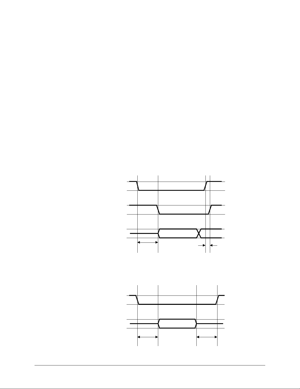
S Register 119 - Quick Enter to Command
By setting this register to 1, a delay of 5 seconds is introduced at power-up
before the modem goes into data mode. If, during these 5 seconds, the user
enters ‘enc’ the modem will instead go into Command Mode, and reply
with ‘OK’. The terminal baud rate must be set to 9600 baud. If an
incorrect character is entered, the modem will immediately go into Data
Mode. The allowable settings for this register are:
*0 Disabled
1 Enabled
S Register 120 - RTS/DCD Framing
S Register 121 - DCD Timeout
The ENC-900 supports two special types of data framing:
• Input (or RTS/CTS) Data Framing; and,
• Output (or DCD) Data Framing
Input Data Framing is enabled by configuring the Handshaking Parameter
as &K2. This type of framing makes use of the S120 parameter as
illustrated in Figure 9. Parameter S120 can be set to any value between 0
and 254 ms.
RTS
CTS
TXD
S120 (ms)
To enable output (DCD) data framing, set the Data Carrier Detect parameter
as &C2. This type of framing uses both S120 and S121 registers as shown
in Figure 10. Valid ranges for each parameter are 0 to 254 ms
Data going into MHX-910
0 to 1 ms
Figure 9 - Input Data Framing
DCD
RXD
Data leaving MHX-910
S120 (ms) S121 (ms)
Figure 10 - Output Data Framing
34 ENC-900 Operating Manual: Chapter 4 Configuration
Page 39

S Register 123 - Remote RSSI Reading
This register displays the average received signal strength in dBm over the
previous four hop intervals. In repeater mode, this register is referring the
RSSI from last received Remote radios. The value in this register is also
reflected in status lines RSSI1,2 and 3.
S Register 124 - Master RSSI Reading
This register will only be used in repeater configuration and display the
received signal strength from Master radio.
S Register 213 - Packet Retry Limit
Packet Retry Limit is analogous to Packet Retransmissions, but specifically
applies to Remotes and Repeaters. This parameter is not used by the
Master. Because the Remote has the advantage of receiving
acknowledgements from the Master, it is not necessary to blindly retransmit
each packet. If the Remote does not get an acknowledgement on the next
hop, it will retransmit its packet. This will continue until the Packet Retry
Limit is reached or an acknowledgement is received. If the limit is reached,
the modem will give up and discard the data. Valid settings are 0 to 255
retries. The default value is 2.
The Repeater makes use of this parameter when it is tuned to its Primary
Hopping Pattern and is acting like a Remote.
ENC-900 Operating Manual: Chapter 4 Configuration 35
Page 40

4.4 Diagnostics, Statistics and Remote Control
The ENC-900 provides several commands which are very useful for
troubleshooting and analyzing the performance of the radio system.
4.4.1 Spectrum Analyzer Feature (ATG)
Issuing the command ATG <return>,causes the ENC-900 to perform a
sweep of the entire operating spectrum, giving a signal strength read-out in
dBm for each channel as shown below:
Noise level, '*'- mean value, '.'- max value
ch 1 -138dBm *
ch 2 -139dBm *
ch 3 -139dBm *
ch 4 -139dBm *
ch 5 -139dBm *
ch 6 -139dBm *
ch 7 -130dBm *
ch 8 -116dBm *
ch 9 -135dBm *
...
ch 127 -135dBm *
Paging -135dBm *
Channel 1 is at frequency 902.4 MHz, with all subsequent channels in 200
kHz increments. This feature also displays average received signal strength
for 12 channels above the 902-928 MHz ISM band. This area of the
spectrum is used by paging networks.
When deploying a network, the spectrum analyzer feature is useful for
determining which parts of the ISM band may be noisy. This knowledge
can be used to select an appropriate hopping pattern, or for creating a
custom hopping pattern which avoids those frequencies.
4.4.2 Statistics (ATP)
The ATP <return> command provides a list of several statistics as follows:
# of data packets sent = 0
# of data packets received = 0
# of Remote's retries = 0
# of Remote's packets dropped = 0
# of Remote's sync errors = 0
# of CRC errors = 0
OK
The ENC-900 starts the statistics count at zero each time the unit is
powered up, or after the ATP command has been issued. By entering the
ATP command, all statistics are cleared back to zero. The maximum limit
for each statistic is 65535.
36 ENC-900 Operating Manual: Chapter 4 Configuration
Page 41

4.4.3 Remote Control and Diagnostics (S101=5)
This is a very powerful tool which allows user to remotely configure and
interrogate all units in a multipoint system from the Master unit. Simply by
having knowledge of the unit address of each Remote/repeater in the
system, users can set the unit address of the master to match that of the
Remote/repeater of interest, set S101=5, go online, and interrogate/modify
virtually all parameters of the remote repeater/Remote unit. It should be
noted that when the master goes online, all other units belonging to the
network will synchronize with the master, but only the unit whose unit
address matches the master’s will respond to the master’s diagnostic
commands.
In addition, in diagnostics mode, the master can change its unit address ‘onthe-fly,’ avoiding the delays of going into command mode, modifying the
unit address, going back online and re-synchronizing with the entire
network, before interrogating a new Remote/repeater. The master’s unit
address can be changed while still maintaining synchronization with the
entire network, allowing for quick and efficient diagnostic sessions with all
remote units. Ensure that register S122=1 on any Remote/repeater that you
wish to remotely modify.
Table 4 provides a diagnostics command summary. The first column is a
list of commands that may be issued at the master. The second column is
the corresponding remote register. In general, any command issued without
any additional parameters is a read command. For example, if you type:
0 <return>
The remote Remote/repeater will send back the value if its S101 register.
On the Master terminal screen, you would see:
0 (this is the 0 that you typed, echoed back locally)
3 (this indicates that the remote’s S101=3)
If you type:
04 <return>
This command would change the remote’s operating mode to S101=4
(repeater). The remote unit should return ‘OK’. Remember, if the remote’s
S122=0 (remote control disabled), the remote will respond with ‘ERROR’.
In Table 4, Column 1, the meanings of the format is as follows:
COMMAND A command without (x) indicates that you may not add any
additional parameters. i.e., you may only read back the value
of the remote’s register. You may not modify that register.
The only exception to this is the WRITE command ‘e’. Type
‘e’ to force the write command (&W) at the remote modem.
COMMAND(x) Indicates this command may be sent with or without a
parameter. Issuing this command without a parameter reads
the corresponding remote’s register. Issuing this command
with the additional parameter ‘x’ changes the corresponding
remote’s register to ‘x’. Remember, any changes you wish to
retain in the event of a power down or reset should be stored to
non-volatile memory by issuing the write command ‘e’.
ENC-900 Operating Manual: Chapter 4 Configuration 37
Page 42

Table 4 - Remote Control and Diagnostics
Command Remote Register Description
0(x) S101 Operating Mode
1(x) S102 Baud Rate
2(x) S108 Output Power
3(x) S110 Data Format
4(x) S115 Repeat Interval
5(x) S116 Character Timeout
6(x) S120 RTS/DCD Framing
7(x) S121 DCD Timeout
8(x) S117 Radio Buffer Mode
9(x) S213 Retry Limit
a test string Read back a test string from remote
b(x) &E Framing
c(x) &C DCD
d(x) &K Handshaking
e &W Write
f S123 RSSI
g(x) S104 Network Address
h(x) S106 Hopping Pattern
I(x) S206 Secondary Hopping Pattern
j(x) S113 Retransmissions
k1 statistics Read # of data packets sent
k2 statistics Read # of data packets received
k3 statistics Read # of Remote's retries
k4 statistics Read # of Remote's packets dropped
k5 statistics Read # of Remote's sync errors
k6 statistics Read # of CRC errors
k255 statistics Clear statistics
l(x) S124 Master’s RSSI
m(x) S118 Roaming
o(x) S119 Quick enter to command
/(x) S114 Low Current Mode
38 ENC-900 Operating Manual: Chapter 4 Configuration
Page 43

As mentioned previously in this section, there are some settings that can be
changed to the master’s own registers while in diagnostics mode. The most
useful is the unit address. By changing the master’s unit address to that of
another Remote in the network while in diagnostics mode, users can quickly
interrogate/modify many different Remote’s settings without the delays
associated with switching between command and data modes. The
commands which apply to the master’s own registers are shown in Table 5.
Table 5 - Master Diagnostics Commands
Command Master Register Description
n(x) - Remote Hop loading
p - Remote IO string read
r(x) S105 Unit Address
s S101 back to normal operating mode
t(x) S109 Hopping Interval
u(x) S104 Network Address
v(x) S106 Hopping Pattern
w S123 Local RSSI
y - Remote IO string write
z S108 Output power level
ENC-900 Operating Manual: Chapter 4 Configuration 39
Page 44

40 ENC-900 Operating Manual: Chapter 4 Configuration
Page 45

A. MODEM COMMAND SUMMARY
The following provides a command summary for the ENC-900 module. Factory settings are denoted with a ‘*’.
AT Commands
A Answer
E Command Echo
E0 No Echo
* E1 Command Echo
I Identification
I0 Product Code
I2 ROM Checksum test
I3 Firmware Version
I4 Firmware Date
I5 Copyright
I6 Firmware Time
O On-line ModeQ Quiet Mode
* Q0 Enables Result Codes
Q1 Disables Result Codes
V Result Codes Display
V0 Display as Numbers
* V1 Display as Words
W Connection Result
* W0 Reports DTE as CONNECT xxxx
W1 Reports computer (DTE) rate and wireless rate
between modems as CARRIER xxxx.
W2 Reports DCE as CONNECT xxxx
Z Reset and load stored configuration
&C DCD (Data Carrier Detect)
&C0 DCD is always on
* &C1 DCD is on when modems are synchronized
&C2 DCD used for output data framing
&D DTR (Data Terminal Ready)
&D0 DTR ignored
* &D2 DTR disconnects and switches to command
&D3 DTR disconnects and resets modem
&E Framing Error Check
*&E0 Framing Error Check Disabled
&E1 Framing Error Check Enabled
&F Load Factory Default
&F1 Master
&F2 Remote
&F3 Repeater
&F4 Remote through Repeater
&K Handshaking
&K0 Disable Handshaking
&K2 RTS/CTS Input Framing
* &K3 Enable Handshaking
&S DSR (Data Set Ready)
&S0 DSR is always on
* &S1 DSR on in data, off in command mode
&V View Configuration
&W Write configuration to memory
Sxx? Read S register value
Sxx=yy Set S register value
Result Codes
0 OK
3 NO CARRIER
4 ERROR
S Registers
S0 Auto Answer [0...255]
0 = power up in Command Mode,
non-zero = power up in Data Mode
S2 Escape code [0...255] default ‘+’
S101 Operating Mode
1 - Master Point to Multipoint
2 - Reserved
3 - Remote
4 - Repeater
S102 Serial Baud Rate
1 = 115200, 2 = 57600, 3 = 38400
4 = 28800, 5 = 19200, 6 = 14400
*7 = 9600, 8 = 7200, 9 = 4800,
10 = 3600, 11 = 2400, 12 = 1200
S103 Wireless Link Rate
*2 = Fast w/o FEC
4 = Fast with FEC
S104 Network Address [0...255]
S105 Unit Address [1...255]
S106 Primary Hopping Pattern [0...61]
S107 Encryption Key [0...255]
S108 Output Power Level
0 = 1 mW, 1 = 10 mW, *2 = 100 mW
3 = 1000 mW
S109 Hopping Interval
*1 = 8 msec, 2 = 12 msec, 3 = 16 msec,
4 = 20 msec, 5 = 30 msec, 6 = 45 msec,
7 = 80 msec, 8 = 120 msec
S110 Data Format
* 1 = 8N1, 2 = 8N2, 3 = 8E1, 4 = 8O1
5 = 7N1, 6 = 7N2, 7 = 7E1, 8 = 7O1
9 = 7E2, 10 = 7O2, 11 = 9N1
S111 Packet Minimum Size [1...Maximum Size]
S112 Packet Maximum Size [2...255]
S113 Packet Retransmissions [0...255]
S114 Low Current Mode
*0 = Disabled, 1 = Enabled
S115 Packet Repeat Interval [1..255]
Default = 1
S116 Packet Character Timeout [0...254 ms]
S117 Radio Buffer Mode
*0 = High Throughput, 1 = Quick Turn Around
S118 Roaming
*0 = Disabled, 1 = Enabled
S119 Quick Enter to Command
*0 = Disabled, 1 = Enabled
S120 RTS/DCD Framing Interval [0...254 ms]
S121 DCD Timeout [0...254 ms]
S123 Remote RSSI value
S124 Master RSSI value
S206 Secondary Hopping Pattern [0...61]
S213 Packet Retry Limit [0...255]
ENC-900 Operating Manual: Appendix A Modem Command Summary 41
Page 46

42 ENC-900 Operating Manual: Appendix A Modem Command Summary
Page 47

B. FACTORY DEFAULT SETTINGS
AT&F1 - Master Default Settings
E1, Q0, V1, W0, S0=0, S2=43, S3=13, S4=10, S5=8
DCD &C2
DTR &D0
Framing &E0
Handshaking &K0
DSR &S1
Operating Mode S101=1
Serial Baud Rate S102=5
Wireless Link Rate S103=2
Network Address S104=1
Unit Address S105=1
Primary Hop Pattern S106=0
Encryption Key S107=*****
Output Power S108=2
Hop Interval S109=1
Data Format S110=1
Packet Minimum Size S111=1
Packet Maximum Size S112=14
Packet Retransmissions S113=0
Low Current Mode S114=0
Packet Repeat Interval S115=1
Character Timeout (ms) S116=1
Radio Buffer Mode S117=0
Roaming S118=0
Quick Enter to Command S119=0
RTS/DCD Framing (ms) S120=5
DCD Timeout (ms) S121=0
Secondary Hop Pattern S206=2
Packet Retry Limit S213=0
AT&F2 - Remote Default Settings
E1, Q0, V1, W0, S0=1, S2=43, S3=13, S4=10, S5=8
DCD &C2
DTR &D0
Framing &E0
Handshaking &K0
DSR &S1
Operating Mode S101=3
Serial Baud Rate S102=5
Wireless Link Rate S103=2
Network Address S104=1
Unit Address S105=2
Primary Hop Pattern S106=0
Encryption Key S107=*****
Output Power S108=2
Hop Interval S109=1
Data Format S110=1
Packet Minimum Size S111=1
Packet Maximum Size S112=14
Packet Retransmissions S113=0
Low Current Mode S114=0
Packet Repeat Interval S115=1
Character Timeout (ms) S116=1
Radio Buffer Mode S117=0
Roaming S118=0
Quick Enter to Command S119=0
RTS/DCD Framing (ms) S120=5
DCD Timeout (ms) S121=0
Secondary Hop Pattern S206=2
Packet Retry Limit S213=0
AT&F3 - Repeater Default Settings
E1, Q0, V1, W0, S0=1, S2=43, S3=13, S4=10, S5=8
DCD &C2
DTR &D0
Framing &E0
Handshaking &K0
DSR &S1
Operating Mode S101=4
Serial Baud Rate S102=5
Wireless Link Rate S103=2
Network Address S104=1
Unit Address S105=3
Primary Hop Pattern S106=0
Encryption Key S107=*****
Output Power S108=2
Hop Interval S109=1
Data Format S110=1
Packet Minimum Size S111=1
Packet Maximum Size S112=14
Packet Retransmissions S113=0
Low Current Mode S114=0
Packet Repeat Interval S115=1
Character Timeout (ms) S116=1
Radio Buffer Mode S117=0
Roaming S118=0
Quick Enter to Command S119=0
RTS/DCD Framing (ms) S120=5
DCD Timeout (ms) S121=0
Secondary Hop Pattern S206=2
Packet Retry Limit S213=0
AT&F4 -Remote Through Repeater Default Settings
E1, Q0, V1, W0, S0=1, S2=43, S3=13, S4=10, S5=8
DCD &C2
DTR &D0
Framing &E0
Handshaking &K0
DSR &S1
Operating Mode S101=3
Serial Baud Rate S102=5
Wireless Link Rate S103=2
Network Address S104=1
Unit Address S105=4
Primary Hop Pattern S106=2
Encryption Key S107=*****
Output Power S108=2
Hop Interval S109=1
Data Format S110=1
Packet Minimum Size S111=1
Packet Maximum Size S112=14
Packet Retransmissions S113=0
Low Current Mode S114=0
Packet Repeat Interval S115=1
Character Timeout (ms) S116=1
Radio Buffer Mode S117=0
Roaming S118=0
Quick Enter to Command S119=0
RTS/DCD Framing (ms) S120=5
DCD Timeout (ms) S121=0
Secondary Hop Pattern S206=2
Packet Retry Limit S213=0
ENC-900 Operating Manual: Appendix B. Factory Default Settings 43
Page 48

44 ENC-900 Operating Manual: Appendix B. Factory Default Settings
Page 49

C. TECHNICAL SPECIFICATIONS
Electrical/Physical
Data Interface Asynchronous Serial Port, TTL Levels
Signals GND, TX, RX, DCD, DSR, DTR, RTS, CTS
Bandwidth / Data Rate 1200 - 115,200 bps, uncompressed half-duplex,
Approx. 50 kbps sustained in intelligent asymmetrical full-duplex
transmission mode
Communications Range1 30 kilometers (19 miles)
Power Requirements 3.8 VDC, 1 Amp
Typical Power Consumption 900 mA at 1W transmit; 28 mA receive and less than 1mA in sleep
Operating Frequency 902-928 MHz
Sensitivity -103 dBm
Output Power 1, 10, 100, 1000mW (user-selectable)
Spreading Code Frequency Hopping
Hopping Patterns 64 pseudo-random, user-selectable
Error Detection CRC-16 with auto re-transmit
Error Correction User-selectable Forward Error Correction (FEC)
Adjacent Channel Rejection > 40 dB
Out-of-band Rejection > 80 dB
Dimensions (LxWxH) 1.7” x 1.7” x 0.5” (42 mm x 42 mm x 13 mm)
Operating Environment Temperature: -40 to +80°C
Humidity: 5 to 95%, non-condensing
Storage Temperature -40 to 90°C
1. Clear line-of-sight, elevated high-gain antennas.
ENC-900 Operating Manual: Appendix C. Technical Specifications 45
Page 50

46 ENC-900 Operating Manual: Appendix C. Technical Specifications
Page 51

Terminology Used in the ENC-900 Operating Manual
D. GLOSSARY
Asynchronous communications A method of
telecommunications in which units of single bytes of
data are sent separately and at an arbitrary time (not
periodically or referenced to a clock). Bytes are
“padded” with start and stop bits to distinguish each
as a unit for the receiving end, which need not be
synchronized with the sending terminal.
Attenuation The loss of signal power through
equipment, lines/cables, or other transmission
devices. Measured in decibels (dB).
Bandwidth The information-carrying capacity of a
data transmission medium or device, usually
expressed in bits/second (bps).
Baud Unit of signaling speed equivalent to the
number of discrete conditions or events per second.
If each signal event represents only one bit condition,
then baud rate equals bits per second (bps) – this is
generally true of the serial data port, so baud and bps
have been used interchangeably in this manual when
referring to the serial port; this is not always the case
during the DCE-to-DCE communications, where a
number of modulation techniques are used to increase
the bps rate over the baud rate.
Bit The smallest unit of information in a binary
system, represented by either a 1 or 0. Abbreviated
“b”.
Bits per second (b/s or bps) A measure of data
transmission rate in serial communications. Also see
baud.
Byte A group of bits, generally 8 bits in length. A
byte typically represents a character of data.
Abbreviated “B”.
Characters per second (cps) A measure of data
transmission rate for common exchanges of data. A
character is usually represented by 10 bits: an 8-bit
byte plus two additional bits for marking the start and
stop. Thus, in most cases (but not always), cps is
related to bits per second (bps) by a 1:10 ratio.
CRC (Cyclic Redundancy Check) An error-detection
scheme for transmitted data. Performed by using a
polynomial algorithm on data, and appending a
checksum to the end of the packet. At the receiving
end, a similar algorithm is performed and checked
against the transmitted checksum.
Crossover cable (Also known as rollover, null-
modem, or modem-eliminator cable) A cable which
allows direct DTE-to-DTE connection without
intermediate DCEs typically used to bridge the two
communicating devices. Can also be used to make
cabled DCE-to-DCE connections. The name is
derived from “crossing” or “rolling” several lines,
including the TX and RX lines so that transmitted
data from one DTE is received on the RX pin of the
other DTE and vice-versa.
Data Communications Equipment (DCE, also
referred to as Data Circuit-Terminating Equipment,
Data Set) A device which facilitates a
communications connection between Data Terminal
Equipment (DTEs). Often, two or more compatible
DCE devices are used to “bridge” DTEs which need
to exchange data. A DCE performs signal encoding,
decoding, and conversion of data sent/received by the
DTE, and transmits/receives data with another DCE.
Common example is a modem.
Data Terminal Equipment (DTE) An end-
device which sends/receives data to/from a DCE,
often providing a user-interface for information
exchange. Common examples are computers,
terminals, and printers.
dBm Stands for “Decibels referenced to one
milliwatt (1 mW)”. A standard unit of power level
commonly used in RF and communications work. n
dBm is equal to 10
10dBm = 0.1mW, -20dBm = 0.01mW, etc.
DCE See Data Communications Equipment.
DTE See Data Terminal Equipment.
Flow Control A method of moderating the
transmission of data so that all devices within the
communications link (DTEs and DCEs) transmit and
receive only as much data as they can handle at once.
This prevents devices from sending data which
cannot be received at the other end due to conditions
such as a full buffer or hardware not in a ready state.
This is ideally handled by hardware using flowcontrol and handshaking signals, but can be
controlled also by software using X-ON/X-OFF
(transmitter on/off) commands.
(n/10)
milliwatt, so 0dBm = 1mW, -
ENC-900 Operating Manual: Appendix D Glossary 47
Page 52

Frequency-hopping A type of spread spectrum
communication whereby the carrier frequency used
between transmitter and receiver changes repeatedly
in a synchronized fashion according to a specified
algorithm or table. This minimizes unauthorized
jamming (interference) and interception of
telecommunications.
Full-duplex Where data can be transmitted,
simultaneously and independently, bi-directionally.
Half duplex Exists when the communications
medium supports bi-directional transmission, but data
can only travel in one direction at the same time.
Handshaking A flow-control procedure for
establishing data communications whereby devices
indicate that data is to be sent and await appropriate
signals that allow them to proceed.
Line-of-sight Condition in which a transmitted
signal can reach its destination by travelling a straight
path, without being absorbed and/or bounced by
objects in its path.
Master The station which controls and/or polls one
or more Remote stations in a point-to-point or pointto-multipoint network. Often functions as a server or
hub for the network.
Non-volatile memory Memory which retains
information which is written to it.
Null modem cable See Crossover cable.
the EIA, a widely known standard electrical and
physical interface for linking DCEs and DTEs for
serial data communications. Traditionally specifies a
25-pin D-sub connector, although many newer
devices use a compact 9-pin connector with only the
essential signaling lines used in asynchronous serial
communications. Lines have two possible states:
“high” (on, active, asserted, carrying +3 to +25 V) or
“low” (off, inactive, disasserted, carrying -3 to -25
V).
RTU (Remote Terminal Unit) A common term
describing a DTE device which is part of a wide-area
network. Often a RTU performs data I/O and
transmits the data to a centralized station.
Serial communications A common mode of
data transmission whereby character bits are sent
sequentially, one at a time, using the same signaling
line. Contrast with parallel communications where
all bits of a byte are transmitted at once, usually
requiring a signal line for each bit.
Shielded cable Interface medium which is
internally shrouded by a protective sheath to
minimize external electromagnetic interference
(“noise”).
Remote A station which is controlled and/or polled
by the Master station for communications. Typically
represents one end of a point-to-point connection, or
one of the terminal nodes in a point-to-multipoint
network. Often a RTU is linked by a Remote DCE.
Point-to-point A simple communications network
in which only two DTEs are participants.
Point-to-multipoint A communications network
in which a Master DTE communicates with two or
more Remote DTEs.
Repeater A device which automatically amplifies
or restores signals to compensate for distortion and/or
attenuation prior to retransmission. A repeater is
typically used to extend the distance for which data
can be reliably transmitted using a particular medium
or communications device.
RS-232 (Recommended Standard 232; more
accurately, RS-232C or EIA/TIA-232E) Defined by
Spread spectrum A method of transmitting a
signal over a wider bandwidth (using several
frequencies) than the minimum necessary for the
originally narrowband signal. A number of
techniques are used to achieve spread spectrum
telecommunications, including frequency hopping.
Spread spectrum provides the possibility of sharing
the same band amongst many users while increasing
the tolerance to interference and noise, and enhancing
privacy of communications.
Throughput A measure of the rate of data trans-
mission passing through a data communication
system, often expressed as bits or characters per
second (bps or cps).
48 ENC-900 Operating Manual: Appendix D Glossary
Page 53
E. APPROVED ANTENNAS
Part
Number
AN-116 2dBi, 900MHz Rubber Duck Antenna Astron, RPTNC 1 W
AN-149 6dBd, 900MHz Omni Directional Antenna Antenex, RPTNC Pigtail 100mW
AN-158 10dBd, 900MHz Yagi Directional Antenna Bluewave, RPTNC Pigtail 100mW
WARNING:
Change or modifications not expressly approved by Encom Wireless Data Solutions Inc. could void the user’s
authority to operate the equipment. This device has been tested with MCX and Reverse Polarity TNC connectors
with the antennas listed in Appendix A.
Maximum allowed TX power on the radio will be factory reduced if antenna gain higher than 6 dBi is ordered. An
ordered antenna will be shipped with the radio module, if a buyer has both modules and substitutes the antennas
between the modules or use another type of antenna, EIRP may be exceed. Violation of FCC regulations can
result in severe fines.
Description Maximum Allowed TX
Power
ENC-900 Operating Manual: Appendix E Approved Antennas 49
Page 54

50 ENC-900 Operating Manual: Appendix E Approved Antennas
 Loading...