

Page 1

Operating Manual
COMMPAK-900
900 MHz Spread Spectrum Transceiver
Rev ision 1.00 March 6, 2001
Encom Wireless Data Solutions Inc.
#7-640, 42nd Ave. N.E.
Calgary, Alberta T2E 7J9
Phone: (403) 230-1122
Fax: (403) 276-95 75
www.encomrs.com
Page 2

COMMPAK-900
900 MHz
Spread-Spectrum
Ra dio Modem
WARNING
In order to comply with the
FCC/IC adopted RF exposure
requirements, this transmitter
system will be installed by the
manu f act urer’s resell er
pro f ession al. Inst allation o f all
antennas must be performed in a
manner that will provide at least
23 cm clearance from the f ront
radi at ing aperture, to any user or
member of the public.
This manual contai ns informatio n of propr iet ar y interest to
Encom Wireless Data Solutions Inc.. It has been
supplied in confidence to purchasers and users of the
COMMPAK-900
recipient agrees that the contents will not be copied or
reproduced, in whole or in part, without prior written
consent of Encom Wireless Data So lutions Inc.
Encom Wireless Data Solutions Inc.. has made every
effort to assure that this document is accurate and
complete. However, the company reserves the right to
make changes or enhancements to the manual and/or
the product described herein at any time and without
notice. Furt hermore, Encom Wireless Data Sol utions Inc.
assumes no liability resulting from any omissions in this
document, or out of the application or use of the device
described herei n.
Encom ’ products are appropriate for home, office, or
industrial use, but are not authorized for utilization in
applications where failure could result in damage to
propert y or human injury or loss of life.
The electronic equipment described in this manual
generates, uses, and radiates radio frequency energy.
Operation of this equipment in a residential area may
cause radio interference, in which case the user, at his
own exp ense, will b e required to ta k e whatever measures
necessary t o corr ect the inter f erence.
, and by accepting this material the
EQUIPMENT LABEL ING
The manufacturer, product
name, and FCC and Industry
Canad a iden t ifiers of this
product must appear on the
outside label of the end-user
equipment.
Encom Wireless D a ta Solu tions Inc
#7-640 42nd Ave. N.E.
Calgary, Alberta T2E 7J9
Phone: (403) 230- 1122Fax: ( 403) 276-9575
www.encomrs.com
FCC Declaratio n of Conf or mity
This device complies with Part 15 of the FCC Rules.
Operat ion is subjec t to the following two condit ions:
(1) this device may not cause harmful interference,
and (2) this device must accept any interference
received including interference that may caused
undesired oper at ion.
Encom Wireless Data Solutions Inc., products are
warranted against all failures which occur as a result of
defective material or workmanship within 24 months of
pur c has e by the use r . T his w ar r ant y do es not ext e nd t o
products that, in the opinion of Encom Wireless Data
Solutions Inc.., have been subject to misuse, accidents,
lightning strikes, improper installation or application, nor
shall it extend to units which have, in Encom Wireless
Data Solutions Inc.’s opinion, been opened, tampered
with or r ep a ired by a n unauthorize d facility.
All Ri ghts Re s e rved . COMMPAK,
tradem ar ks of Encom Wireless Dat a Solution s Inc. Microsoft and
Window s are register ed tradem arks of Microsoft Cor poration.
pcANYW H ERE and Symantec are regist er ed tradem arks of Symantec
Corp. All other products mention ed in this docum ent are tradem arks or
registered t r adem arks of their respective holder s.
Manu al Rev ision 1.00, March 6, 2001.
ControlPAK
are register ed
Page 3

NTRODUCTION
1. I
.................................................................................................................................................................................................2
1.0 Product Overview..............................................................................................................................................2
1.0. 1 DC Characteristics.........................................................................................................................4
OWER CONNECTION
2. P
ODES OF OPERATION
3. M
.....................................................................................................................................................................................5
..................................................................................................................................................................................6
3.1 Master Mode............................................................................................................................................... 6
3.2 Repea ter Mode ...........................................................................................................................................6
3.3 Slave Mod e.................................................................................................................................................6
3.4 Network Topologies.....................................................................................................................................7
ATA PORT
4. D
.......................................................................................................................................................................................................2
4.1 RS232 C onfiguration...................................................................................................................................2
4.1. 1 Sleep M ode ................................................................................................................................... 3
4.2 4 W ire RS485 C onfiguration ........................................................................................................................ 3
4.3 2 W ire RS485 C onfiguration ........................................................................................................................ 4
5. LED I
NDICATORS
............................................................................................................................................................................................5
5.1 PW R (R ed) .................................................................................................................................................5
5.2 TXD (Red) .................................................................................................................................................. 5
5.3 RXD (Red)..................................................................................................................................................5
5.4 RSSI........................................................................................................................................................... 5
5.4.1 MASTER....................................................................................................................................... 5
5.4.2 LOCAL..........................................................................................................................................5
5.4. 3 MAS TER and LOCAL....................................................................................................................5
5.4.4 REPEATER...................................................................................................................................5
NSTALLATION
6. I
..................................................................................................................................................................................................6
6.1 Antenna, Fee dline & Inter nal R F Jumper Sel ection......................................................................................6
6.1.1 Antennas....................................................................................................................................... 6
6.1.2 Feedlines......................................................................................................................................7
6.1. 3 Inter n al RF Jumper........................................................................................................................8
6.2 How Much Output Power Can be Used?......................................................................................................9
6.3 Antennas, Feedline & Lightning Arre stors Install ation.................................................................................. 10
6.3. 1 Antenna Installation..................................................................................................................... 10
6.3. 2 Feedline I nst allation..................................................................................................................... 11
6.3. 3 Lightni ng A rrestors Installation..................................................................................................... 11
ONTROL
7. C
7.1 ControlPAK
CONFIGURATION SOFTWARE
PAK
Software Installation............................................................................................................ 12
......................................................................................................................................12
7.2 Seri al Con nection...................................................................................................................................... 12
7.3 ControlPAK
Operati on ............................................................................................................................ 13
7.3. 1 Log In.......................................................................................................................................... 13
7.3. 2 Ini tia l Menu.................................................................................................................................. 13
7.3. 3 Conf ig uration Menu ..................................................................................................................... 14
7.3. 4 Soft w are - Connecti on ................................................................................................................. 15
7.3. 5 Soft w are - D isconnec t.................................................................................................................. 17
7.3. 6 Conf ig uration - Radi o Option s ...................................................................................................... 18
7.3. 7 Output Power Se lection ............................................................................................................... 18
7.3. 8 Hopping Patterns......................................................................................................................... 20
7.3. 9 Unit Address................................................................................................................................20
7.3. 10 Encrypti on Key.......................................................................................................................... 21
7.3. 11 Confi gur ation – Ad vance d Radi o Options................................................................................... 22
7.3. 12 Conf ig ur ati on –Radi o Ti ming Par am eter s................................................................................... 23
7.3. 13 Confi gur ation –Radio Ha ndsha king Para m eters.......................................................................... 25
7.3. 14 ControlPAK Version................................................................................................................... 26
7.3. 15 Radio Program ming................................................................................................................... 27
7.3. 16 Saving Configurati ons To Files .................................................................................................. 27
7.3. 17 Loadi ng Conf igura ti ons From Fi les............................................................................................. 27
8. COMMPAK-900
TECHNICAL SPECIFICATIONS
..................................................................................................................................28
8.3. 1 Electri cal/Environm ent S pecification s: .......................................................................................... 28
8.3. 2 Mechanical S pecification s:........................................................................................................... 28
8.3. 3 Seri al Da ta Inter face S pec ifications:............................................................................................. 28
8.3. 4 Radio Specificati ons: ................................................................................................................... 28
1
Page 4

1.
Introduction
1.0 Product Overview
The
COMMPAK-900
- 928 MHz ISM band, this frequency-hopping spread-spectrum module is capable of providing reliable
wireless data transfer between almost any type of equipment which uses an asynchronous serial
interface. The small-size and superior RF performance of this module make it ideal for many
applications. Typical uses f or this module incl ude:
SCADA
!
Traffic Control
!
Remote Monitoring
!
Telemetry;
!
Remote Camera/Robot Control;
!
Security Syst ems; and,
!
Display Signs.
!
While a pair of
multiple modules can be used together to create a network of various topologies, including “point-tomultipoint” and “repeater” operation. Multiple independent networks can operate concurrently, so it is
possible for unrelated communications to take place in the same or a nearby area without sacrificing
privacy o r re liability.
is a high-performance embedded w ireless data tr ansceiver. Oper ating in the 902
COMMPAK-900
modules can link two terminal devices (“point-to-point” operation),
1.1 Featur es
Key features of t he
COMMPAK-900
include:
transmission within a public, license-exempt band of the radio spectrum1 – this means that it
!
can be used without access fees ( such as those incurred by cell ular airti me);
a serial I/O data port with handshaking and hardwar e flow control, allowing the
!
to interface directly to any equipment with an asynchronous serial interface.
900
64 sets of user-selectable pse udo-random hopping patterns, i ntelligently desig ned to off er the
!
possibility of s epar at ely operating multiple networks w hile providing securit y, r eliabilit y and
high tolerance to interference;
encryption key with 65536 user-select able values to maximize sec urity and privacy of
!
communications;
built-in CRC-16 err or det ection and auto re- transmit to provide 100% accuracy and reliability
!
of data;
ease of installatio n and use – the
!
configur ation utility nam ed ControlPAK. This software provide simple access to all
parameters w it hin the radio module.
While the typical application for the
communications li nk betw een DTEs, it can be adapt ed to almost any sit uatio n where a n as ynchronous
serial interfac e is used and data intercommunicat io n is req uired.
1
902-928 MHz, which is license-free within North America; may need to be fac tory-configured differe ntly fo r some co untries.
COMMPAK-900
COMMPAK-900
modul e uses a Windows based
is to provide a short- to mid-range wireless
COMMPAK-
2
Page 5
1.2 About this Manual
This manual has been provided as a guide and reference for installing and using
COMMPAK-900
wireless modem modules. The manual co ntai ns instructi ons, suggestions, and informatio n which will help
you set up and achieve optimal perfor mance f r om your equipment usi ng the
It is assumed that users of t he
COMMPAK-900
module have either system integr at io n or system desig n
COMMPAK-900
module.
experi e nce. Thro ugho ut the ma nual, you w ill e ncou nter not only ill us tr at ions tha t f urt her elaborat e on the
accompanying text, but also several symbols which you should be attentive to:
Caution or W ar ning:
coul d result in undesired or detrim ent al consequences.
Point to Remember:
is worth n oting, Keeping these in mind will make using the
COMMPAK-900
An idea or suggestion is provided to improve efficiency or to
Tip:
make something more useful.
With that in mind, enjoy extending the boundaries of your communications with the
Usually advises against some action which
Highlights a key feature, point, or step which
more useful or easier to use.
COMMPAK-900
module.
3
Page 6

1.0. 1 DC Characterist ics
Pins Characteristic Min Typ Max Units
AV
DV
V
V
AI
AI
AI
AI
AI
DI
V
V
I
SRCE
POT
RST
CCR
CCT0
CCT1
CCT2
CCT3
V
V
CC
IL
IH
OL
OH
Radio Supply Voltage 4.9 5.0 5.5 V
CC
Logic Supply Voltage 4.75 5.0 5.5 V
CC
Power On Reset Threshol d Voltage 1.8 2 2.2 V
Reset Pin Threshold Voltage DVCC/2 V
Radio Supply Cu rrent in Receive
Mode
Radio Supply Cu rrent at 1mW
Transmit
Radio Supply Cu rrent at 10mW
Transmit
Radio Supply Cu rrent at 100mW
Transmit
Radio Supply Cu rrent at 1W Transmit 398 442 486 mA
Logic Supply Cur r ent 95 105 115 m A
In put Low Voltage (Pins 23,24,27) -0.5 .3DV
In put High Voltage ( Pins 23,24, 27) 0.6V
Output Low Voltage (Pin s
21,22,26,28-33)
Output High Volt age (Pins
21,22,26,28-33)
Sourcing Current (Pins 21,22,26, 28-
33)
96 107 117 mA
68 108 119 mA
111 123 135 mA
157 174 191 mA
V
CC
CC
VCC+.5 V
0.6 V
4.2 V
10 mA
Caution:
Using any other power supply which does not provide the proper voltage or current could damage the
COMMPAK-900
module.
IMPORTANT:
For best pe r f or m anc e, it is
strongly recomme nded t o use a
separat e, linearly r egulated supply
for Vcc Radi o. Do not directly
feed a swi t ching power supply
into Vcc Radi o.
4
Page 7

2.
Power Connection
The
COMMPAK-900
The
COMMPAK-900
30 VDC fused power source and is designed for use in ne gative ground systems only. The a ntenna must
be connected to the radio prior to applying pow er t o it.
Power connection to the
Power Cable Red lead To power supply fused +VDC
Power Cable Black lead To power supply ground
power port provides a polarized locking power connection for the power cable.
is supplied w ith a 72-inch power cable. The
COMMPAK-900
Cable Leads Power Supply Connect i ons
is as fo llows:
COMMPAK-900
requires a 10 to
5
Page 8

3.
Modes of Operation
The
COMMPAK-900
The module is designed such that all communication is through one serial port (Pins 21 to 28 on the
module). There are t hree basic mode of operations to any
One and only one module configured as the
•
Zero or more modules config ured as
•
One or more modules configured as
•
modem can be easi ly configured to meet a wide range of needs and applications.
COMMPAK-900
Master
Repeaters
Slaves
communications netw or k:
3.1 Master Mode
The function of the Master is to provide sync hroni zation for the entire networ k, and t o control the f low of
data. There is always one Master per network. The Master is the ultimate destination for all data
collected at the various Repeater’s and Slave’s serial ports. With the network set up for Point-toMultipoint comm unicati on, all data received at the Master’s serial port is transm it ted to every Repeater
and Slave in the network. The
“hops” to a new fr equency after a predetermined time i nterval. This time interval is a fixed time set by the
user, and can range from 8ms to 120ms. The
patter n of 50 diff erent channels. There are two Master modes can be select ed:
1.
Master Point-to-Point
directly, or through one or more Repeater s.
2.
Master Point-to-Multipoint
Slaves and/or Repeater s.
COMMPAK-900
: The modem is conf i gured to communicate w it h a single Slave, either
: The modem is configured to communicate with one or more
is a frequency hopping transceiver, meaning that it
COMMPAK-900
hops according to a pseudorandom
3.2 Repeater Mode
Any
COMMPAK-900
configured to pass information from either a Master or another parent Repeater onto subsequent
Repeaters and/or Slaves and vice versa. The Repeater also acts as a Slave in the sense that, like a
Slave, it passes information to/ f r om its ser ial port .
can be configured as Repeater Mode. In Repeater mode, the modem is
3.3 Slave Mode
When configured as a Slave, The modem communicat es with one Master eit her directly or t hrough o ne or
more Repeaters. Before establishing any communication, the slave configured
search and synchro nize with t he direct Mas t er or the parent Repeater.
COMMPAK-900
will
6
Page 9
3.4 Network Topologies
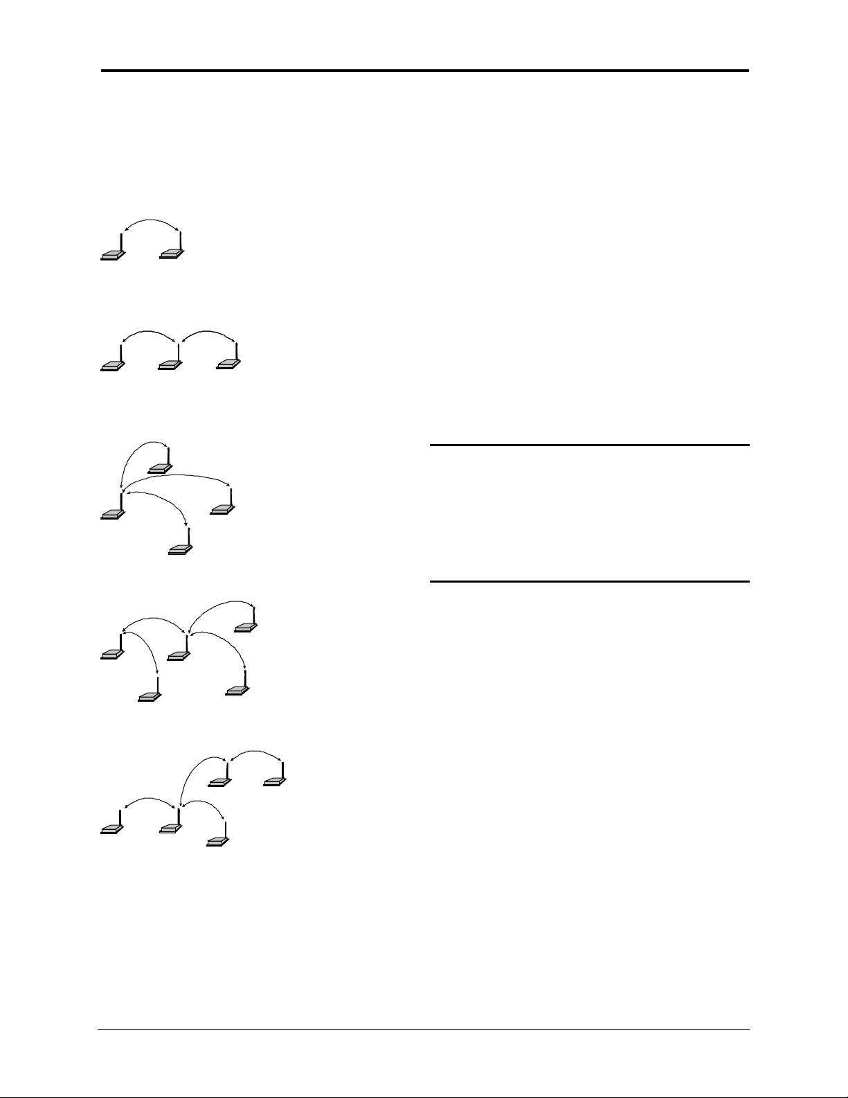
Networ k topologies consisting of a single Master and virtually any com bination of Sla ves a nd Repeat ers
may be deployed.
Examples of differ ent net work t opologies are shown
M
Network 1
MSRM
Network 2
S
M
Network 3
Network 1
S
between a Mast er and Slave.
Network 2
shows Point-to-Point communication
makes use of a Repeater to
communicate with the Slave.
Network 3
illustrates a simple Point-to-Multipoint
network w ith no Repeaters.
SR
Networks 4 and 5
Multipoint networks consisting of both Repeaters
give examples of Point-to-
and Slaves.
NOTE:
There is effectively no restriction to the
number of Repeaters and Slaves that can
S
be added to a network. As seen in
Network 4, a Master can communicate
directly wit h both Slaves and Repeaters
S
S
M
R
S
S
Network 4
MR
S
Network 5
SR
7
Page 10

Data Port
The
COMMPAK-900
2 Wire RS485 or 4 Wire RS485 or HART operatio n. Radios configured for RS485 or HART operation
are supplied with a programmi ng cable, w hich permits direct connecti on to a comput er f or pr ogr amming.
is availab le with a standard RS232 data configuratio n or optionally co nfigured f or
3.1 RS232 Configuration
The standard
that supports the RS-232 type format. This serial interface port meets the EIA RS-232C interface
standard and is provided on a DE-9 female connector. A standard RS232 modem cable is used for
programmi ng the RS232 config ured
COMMPAK-900
Pin
Number
1OUTPUT
2OUTPUT
3INPUT
4INPUT
5
RS232 serial port is used to connect the radio to peripheral eq uipme nt
COMMPAK-900
Input or
Output
DCD
RXD
Outputs RX data to the connected device.
TXD
Accepts TX data f r om the connected device.
DTR
Low = Enables Sleep Mode.
High = Disables Sleep Mode and reactivates the radi o
Signal Gr ound
.
Pin Desc ript ion
–Data Car r ier Det ect .
– Recei ved Data.
– Transmitted Data.
– Sleep Mode Enable. *** see below
– Common DC ground.
6 Not Used
– Request to send.
7INPUT
8OUTPUT
9 Not Used
RTS
– Clear to send.
CTS
2
Page 11
3.1.1 Sleep Mode
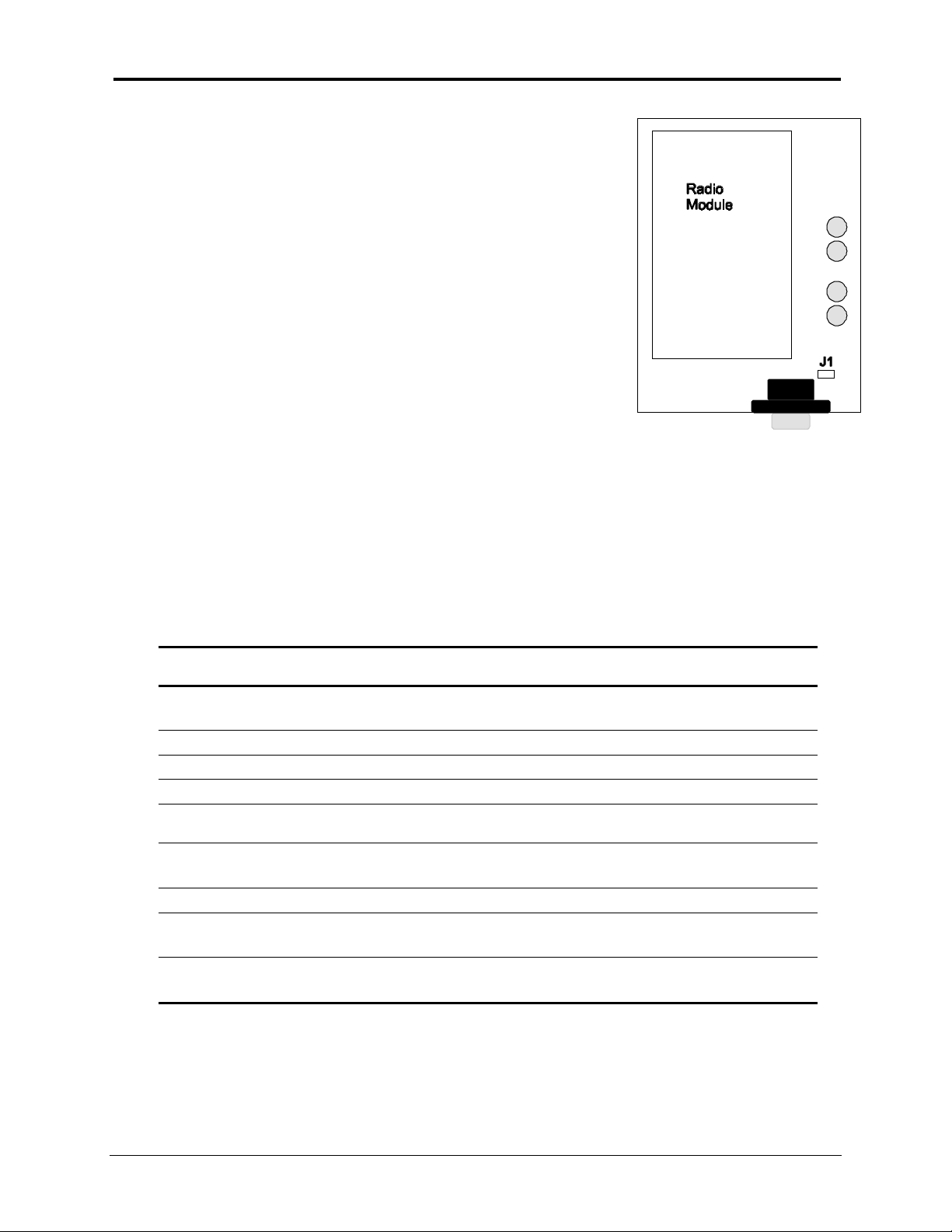
The COMMPAK-900
Sleep Mode function disabled. The Sleep Mode function is
enabled by removing J1, the diagram on the left indicates the
location of J1.
With J1 removed the radio Sleep Mode can be activated by tying
Pin 4 of the RS232 dat a port low. The radio is reactivated and S leep
Mode deactivated by ty ing this pin high.
When J1 is removed to activate the Sleep Mode function, Pin 4 m ust
be tied eit her hig h or low . The radio will not f unctio n cor rect ly if J 1 is
removed and Pin 4 of the data port is left unconnected.
is normally configured with the
3.2 4 Wire RS485 Configuration
The
COMMPAK-900
either Full or Half Duplex mode. The 4 Wire RS485 Data Port connections are provided on the DE-9
female connector and are o utlined below.
The
COMMPAK-900
configured radio directly to your computer for progr amming.
radio configured f or 4 Wire RS485 operation may be programmed to oper ate in
radio is provided w ith a programming cable that allows you to connect the RS485
Pin
Number
1OUTPUT
2 Not Used
3 Not Used
4 Not Used
5
6OUTPUT
7 Not Used
8INPUT
9INPUT
Input or Out put Pin Descriptio n
RX+
Outputs RX data to the connected device.
Signal Gr ound
RX-
Outputs RX data to the connected device.
TX+
Accepts TX data f r om the connected device.
TX-
Accepts TX data f r om the connected device.
Received Dat a .
Received Data.
Transmitted Data.
Transmitted Data.
3
Page 12

3.3 2 Wire RS485 Configuration
The 2 Wire RS485 Data Port connectio ns are pr ovided on t he DE-9 female connec tor and are outlined
below.
Pin
Number
1 INPUT / OUTPUT
2 Not Used
3 Not Used
4 Not Used
5
6 INPUT / OUTPUT
7 Not Used
8 INPUT / OUTPUT
9 INPUT / OUTPUT
4 leads are used for the 2 Wire RS485 data connect i ons, as well as a ground connection.
Note:
Pins 1 and 8 must be tied together for T/ R +. Pins 6 a nd 9 must be tied toget her f or T/R-.
Input or Out put Pin Description
T/R +
Signal Gr ound.
T/R -
T/R +
T/R -
Transmit / Rece iv e d ata po s itive lead.
Transmit / Receive data negati ve lead.
Transmit / Rece iv e d ata po s itive lead.
Transmit / Receive data negati ve lead.
4
Page 13

4.
LED Indicators
The
COMMPAK-900
functions are as follows:
4.1
On both the Master and Local radios, t he PWR LED indicates the radio is powered on.
The PW R L ED will be ON solid w hen powe r is applied to the radio.
4.2
On both the Master and Local radios, the TXD LED indicates the radio is TRA NSMI TTI NG data.
4.3
On both the Master and Local radios, t he RXD LED indicates t he radio is RECEIVING data.
PWR
TXD
RXD
(Red)
(Red)
(Red)
radio front panel LEDs indicate its operational status. The LEDs and their
4.4 RSSI
4.4.1 MASTER
The RSSI LEDs ind icate the level of t he received signals from the Local Intersect ions. The LEDs initially
remain OFF until a sig nal is received from any Local. Following the initial recei ved signal the RSSI LEDs
indicate the level of the received sig nal fr om each Local Inters ect ion as they transmit , as det ailed below. If
communications to all Remote and/or Repeater sites is lost the RSSI LEDs wil l remain ON for 3 minut es,
the n all the RS S I LEDs will turn OFF .
4.4.2 LOCAL
The RSSI LEDs indicate the level of the received sig nal from the MASTER. The LEDs will FLA SH in
sequence if the Local radio is not locked to the Master. When the Local is locked to the Master the
number of LEDs o n or fla shi ng will i ndic at e the le ve l of t he s ignal re cei ved f ro m t he M ast er Inte rs ect ion,
as detailed below.
4.4. 3 M AS TER and L OCAL
A single flashing LED indicat es a very poor and unusable signal. Three LEDs O N SOLID ind icate a very
strong and reliable received signal.
4.4.4 REPEATER
The RSSI LEDs will i n dic a te t he r e c eived R F s igna l level from t he M as ter .
In multi ple Repeater syst ems, the RSSI LEDs will ind icat e the re cei ved RF sig na l le vel f rom t he upstr eam
Repeater.
5
Page 14
5.
Installation
5.1 Antenna, Feedline & Internal RF Jumper Selection
5.1.1 Antennas
The equip ment can be used with a number of antennas. T he exact style used depe nds o n the physic al
size and layout of a system. Contact your Encom representative for specific recommendations on
antenna types and hardware sources.
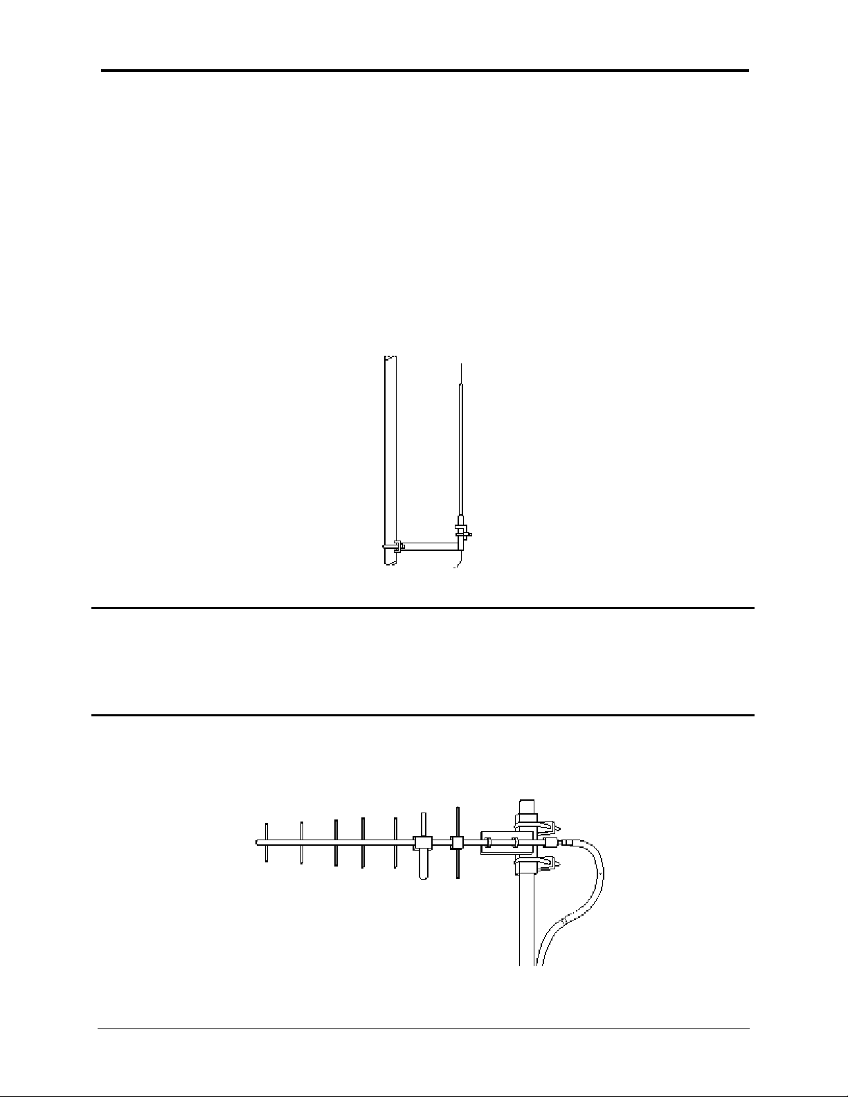
In ge neral, an omnidirectional antenna is used at the mast er station site in a Point- to-Mult ipoint system.
This provides equal coverage to all of t he remote sites.
NOTE:
At remote sites and point-to-point systems, a directional Yagi antenna is generally recommended to
minimize interf er ence to and from other users. Ante nnas are available fr om a number of manufacturers.
Antenna polarizatio n is important. If the wr ong polarization is used, a signal reduction of 20
dB or more w ill result. Mo s t syst e ms using a gain-t y pe o m n id irectio n al antenna at the mas ter
station employ vert ical polarizati on of the signal; therefore, the remote antenna(s) must also
be vertically polarized (ele me nts oriented perpendicular to the horizon).
6
Page 15

5.1.2 Feedlines
The choice of feedli ne use d with the antenna should be carefully co nsidered. Poor quality coaxial cabl es
should be avoided, as they will degrade system performance for both transmission and reception. The
cable should be kept as short as possible to minimize sig nal loss.
For cable runs of less than 20 feet ( 6 met ers), or for short range transmission, a n inexpensive t ype suc h
as Type RG8A/U or LMR 195 may be acceptable. Ot herwise, w e recommend using a low - loss cable t ype
suited for 900 MHz, such as LMR or He lia x
The following table list sever al types of f eedlines a nd indicates t he signal losses (in dB) that result w hen
using various lengt hs of each cable at 900. The choice of cable will d epend o n the req uir ed lengt h, cos t
consideratio ns, and t he amount of sig nal loss that can be tolerated.
Cable Type
RG-8 8.54 dB
LMR 195 10.7 dB
LMR 400 3.9 dB
LMR 600 2.5 dB
½ inch HELIAX 2.29 dB
7/8 inch HELIAX 1.28 dB
1 ¼ inch HELIAX 0.95 dB
®
.
100 Feet
(30.48 Meters)
7
Page 16
5.1. 3 In t ernal RF Jumper
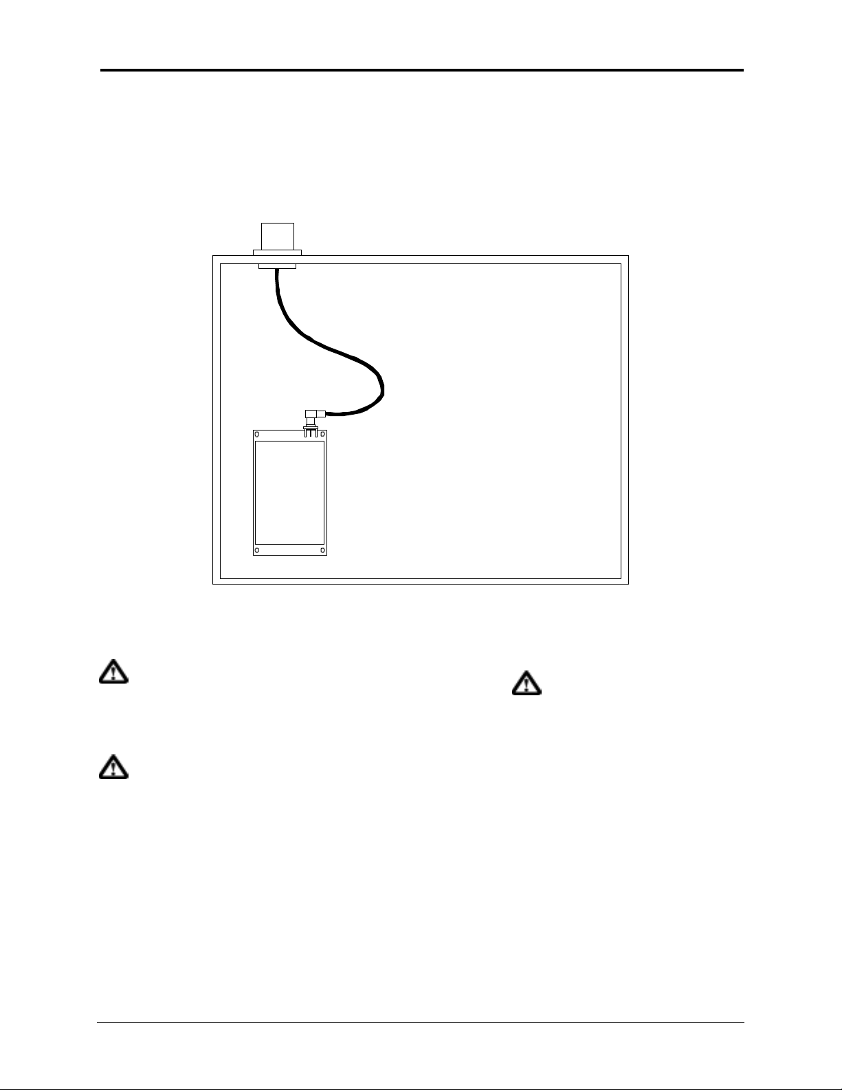
The most common method for installi ng the module is to r un a cable from the mod ule’s M CX c onnector t o
a reverse TNC bulkhead connector on the chassis of the equipment as shown in t he following figure.
This cable is supplied by Encom Wireless Data Sol utio ns I nc.
Rev erse TNC Conn ecto r
RG316 Cable
with MCX male
connector
and Reverse TNC
bulkhead
connector
MCX female connector
COMMPAK
900
Figure 11.
Cable losses are negligible for the short piece used w ithi n t he chassis. Addit io nal losses up to 0.5 dB
may be present in the MCX and Reverse TNC connections.
The installation, removal or
maintenance of all ant e nna
comp onents must be carri ed
out by q ua lifi ed and
experienced personnel.
Never work on an antenna
system when there is
lightning in the area.
Direct human contact wi t h the
antenna is potentially
unhealthy when the
COMMPAK-900 is generating
RF energy. Always ensure
that the COMMPAK-900
equ ipm e nt i s pow ered down
during ins ta llatio n .
8
Page 17

5.2 How Much Output Power Can be Used?
The
COMMPAK-900
power output sett ing; this is t he maximum tr ansmitter outp ut power allowed under FCC rules. The power
must be decreased from this level if the antenna system gain exceeds 6 dBi. The allowable level is
dependent on the antenna gai n, feedli ne loss, a nd the transmitter outp ut pow er setting
NOTE:
To determine the maxim um allowable power set ting of the radio, perform the following steps:
1. Determine the antenna system gain by subtracting the feedline loss (in dB) fr om t he ante nna gai n
2. Subtract the antenna system gain from 36 dBm (the maximum allowable EIRP). The result
In some countries, the maximum allowable RF output may be limited to less than 1 watt
(e.g. , 100 mW /+20 dBm). Be sure to check for and comply with the requirements for y our
area.
(in dBi). For example, if t he ante nna gain is 9.5 dBi, and the feedline loss is 1.5 dB, the ante nna
system gain would be 8 dB. (If the antenna system gain is 6 dB or less, no power adjust ment is
required.)
indicates the maximum transmitter power (in dBm) allowed under the rules. In the example
above, this is 28 dBm.
is normally supplied from the factory set for a nominal +30 dBm (1 Watt) RF
To comp ly with FCC
regula tions, .y o u mus t limit
ERP to 36 dBm or less.
3. If the maximum transmitter power allow ed is less t ha n 30 dBm, use the
(described on next sect ion) to reduce the power accor dingly.
For convenience, the following table lists several antenna system gains and shows the maximum
allowable power set ting of the radio. Note that a gain of 6 dB or less entitles you to operat e t he radio at
full power output—30 dBm (1 w att ).
ControlPAK
Software
Antenna System Gain
(Antenna Gain in dBi* minus
Feedline Loss in dB†)
6 (or less) 30 36
82836
10 26 36
12 24 36
14 22 36
16 20 36
* Most antenna manufacturers r at e ante nna gain in dBd in their literat ure. To c onvert t o dBi, add 2.15 dB.
† Feedline los s varies by cable t ype and length. To determine the loss for common le ngths of feedli ne,
see Table on page 13.
M aximum Power Set t ing
(in dBm)
EIRP
(in dBm)
9
Page 18
5.3 Antennas, Feedline & Lightning Arrestors Installation
The inst allation, remo val or maintenance of all ante nna components must be car ried out by qualified and
experienced personnel.
NOTE:
Never work on an antenna system when there is li ghtning in the area.
Direct human co ntact with the ante nna is pote ntial ly unhealthy when the
is generating RF energy. Always ensure that t he
COMMPAK-900
equipment is powered
COMMPAK-900
down during installation.
5.3.1 Antenna Installation
For optimum performance of directional antennas, they must be accurately aimed in the direction of
Master or Parent Repeater Radio. The easiest w ay to do this is t o poi nt t he antenna in t he appr oximate
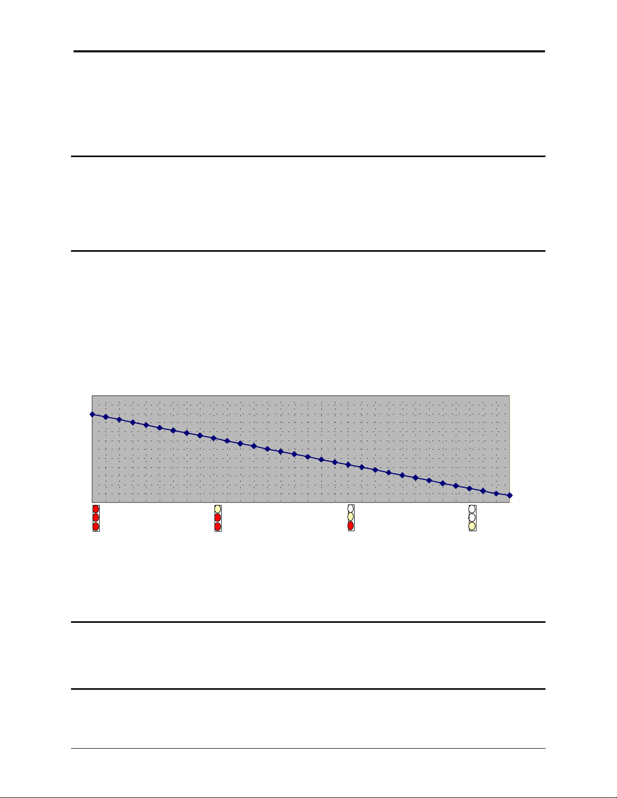
directio n, then use t he radio’s built-in Received Signal Str engt h I ndicat ion (RSSI) LEDs to further ref ine
the heading for maximum received signal strength. The brighter the 3 RSSI LEDs, the better the
Received signal strength. The effective range for the RSSI LEDs is from –70 dBm to –115 dBm and
resolutio n details are listed o n the following diagram.
COMM PAK-900 RSSI RESPONSE CURVE
-60.0
-70.5
-71.9
-73.4
-74.9
-76.4
-77.9
-79.4
-80.9
-82.4
-83.8
-85.3
-86.8
-88.3
-89.8
-91.3
-92.8
-94.3
-95.8
-97.3
-98.7
-100.2
-101.7
-103.2
-104.7
-106.1
-107.6
-109.1
-110.6
-112.1
-113.5
-115.0
-70.0
-80.0
-90.0
-100.0
-110.0
-116.0
-120.0
dBm
Once the equipment is deployed, you can verify the signal st rength in all Repeat er and Slave radios by
using
ControlPAK
ControlPAK
Software are ranging from –50 dBm to –120 dBm, which provides the average signal
Software at the Master radio location. The RSSI readings provided by the
strength readings i n both directions (f r om Mast er to Repeater / Slave and from Repeater/ Sla ve to Mas t er).
NOTE:
The minimum signal strength for communication is roug hly –105 dBm. For consistent reliable
communication, you should try to deploy the equipment such that signal strength exceeds –95 dBm
10
Page 19

5.3.2 Feedline Installation
When installing the feedline, alw ays begin fasteni ng at the top near the antenna connector/surge ar r es t or .
The feedline must be supported at the top with a hose cla mp or wr ap lock, and at 5 ft intervals dow n the
length of the tower. Over-tightening the fasteners will dent the feedline and reduce performance. If
properly grounded surge arr estors are not instal led at both the top and the bottom of the feedline, then
the feedline should be grounded to t he tower at these locations using a cable groundi ng kit. If the t ower
is non-conducti ve, then a separate conductor, physically separate f rom the feedline, should be run down
the tower.
To comp ly with FCC
regula tions, .y o u mus t limit
ERP to 36 dBm or less.
5.3. 3 Li ghtni ng Arrest ors In st allat ion
The most effective protection against lightning is to install two lightning (surge) arrestors. One at the
antenna, and the other at t he interface with the radio equipment. The surge arrestor grounding system
should be fully interco nnected with the tr ansmission tower and power grounding systems to form a single,
fully integrat ed gr ound circ uit. Typically, bot h ports on surge arr es t or s are N-female.
NOTE:
Lightning Arrestors
communication network. But Encom would strongly recommend to have at least one
Lightning Arrestor (nearly the radio equipment end) installed in each radio location (no
matter is Mas t er, Repeater or Slave) to prot ect the equipment.
External Filter :
environments, there are circumstances that require external filtering. Paging towers, and
cellular base stations in close proximity to the
the receiver. Encom’s external cavity filter eliminates this problem. The filter has two Nfemale ports and should be connected in li ne at the interf ace t o the RF equipment.
Weatherproofing:
outdoor connections should be weatherproofed by taped with rubber splicing tape
(weat herproof ing tape), and then coated wit h a sealant.
are not the compulsory items to form a good working wireless
Although the
Most of the RF connectors are not weatherproof by themselves. All
COMMPAK-900
is capable of filter ing out RF noise in most
COMMPAK-900
antenna can desensitize
11
Page 20

6.
ControlPAK Configuration Software
ENCOM Wireless Data Solutions has developed the
COMMPAK-900
6.1 ControlPAK
1. Insert Disk #1 into your P.C.
2. Click t he Start button. Click Run.
3. Click t he Browse button. Locat e and select the
4. With the
5. The
6. Your installation may require only 2 of t he 3 disks.
radio.
ControlPAK
ControlPAK
Software Installation
Set Up file path in the RUN menu screen, click OK.
sof twar e will now b e installed o n your co mputer .
6.2 Serial Connection
1. The
2. Connect the
COMMPAK-900
RS485 , which eliminates the requir eme nt for a dat a convertor.
COMMPAK-900
A. RS232 Config urat ion - Use a standard st raight through serial cable, which i ncl udes
all serial connections.
radio provides RS232 Programming capability for radios configured for
radio Data port to your PC as follows;
ControlPAK
ControlPAK
software for configuration of the
Set Up file.
B. RS485 Configuratio n – Use the supplied RS485 progr ammi ng cable.
12
Page 21
6.3 ControlPAK
Operation
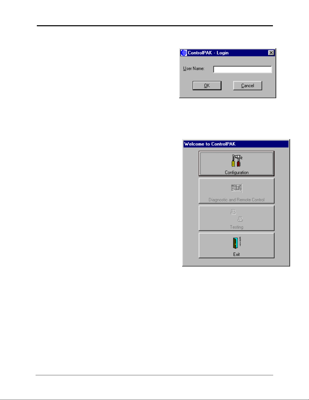
6.3.1 Log In
1. Click on the
2. User Name = SCADA
ControlPAK
Icon to launch
ControlPAK
.
6.3.2 Initial Menu
Configuration
Select this menu to continue with the configuration of your radio.
Diagnostic and Remote Control
This feature is currently undergoi ng final t est ing and completio n.
Testing
This feature is currently undergoi ng final t est ing and completio n.
EXIT
Select EXIT to q uit
ControlPAK
.
13
Page 22
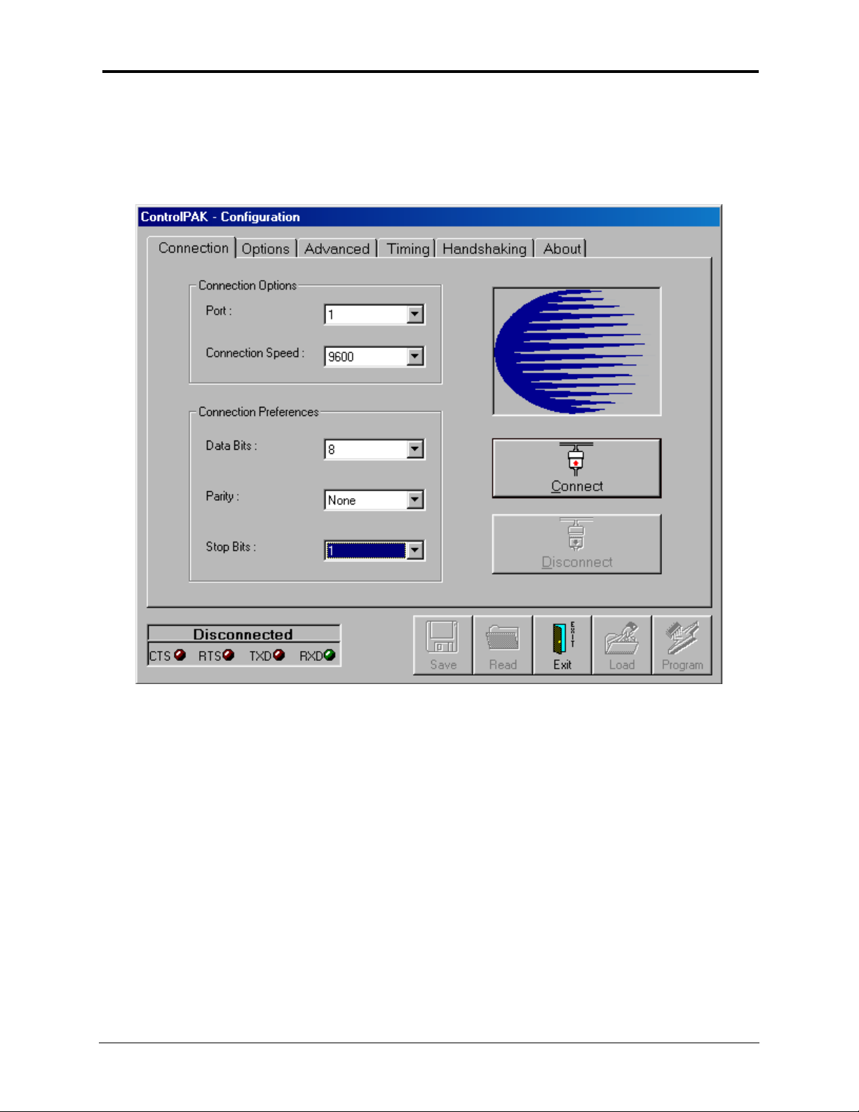
6.3.3 Configuration Menu
When the Configuration menu is selected in the previous step the main Configuration screen, shown
below, will appear.
14
Page 23
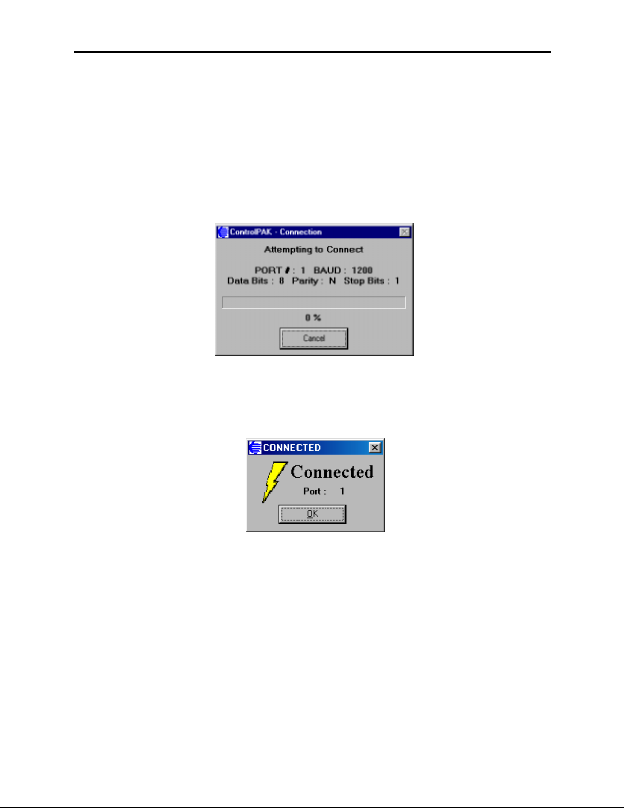
6.3. 4 Sof t ware - Connection
1. The
2. O nly the C onnectio n and About menus can be accessed before a connectio n is est ablis hed. If
3. Select the computer Port number t hat t he radio is connected t o.
4. Enter the radio’s current baud rate and data format, if available, which will speed up the
5. Click on Connect. The message: Attempting to Co nnect, s hown on the below, will appear.
ControlPAK
the connection has not been established an Error Message will appear, when you attempt to
access the other Configuratio n me nus.
Con nection proc edure , however the sof twa re will Connect wit ho ut these entrie s .
software must first be connected to the
COMMPAK-900
radio.
6.
ControlPAK
connectio n from the radio to t he computer.
7. When the connection has been established the message Connected shown on below, will
appear. The radio’s current baud rate and data format will be shown in the Connection menu.
Click OK.
will aut omat ically deter mine the r adio ba ud rate and data f ormat and establis h a
15
Page 24
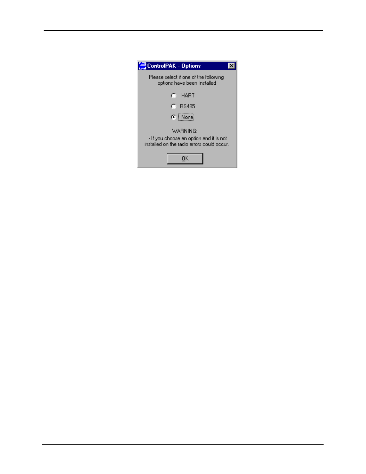
8. The next menu requires you to select if the
RS485 option installed. Select none if the radio is configured f or RS232 operat io n.
COMMPAK-900
radio has either the HART or
9. If the
Note:
ControlPAK
will appear.
When the
the ControlP AK
OFF indicating t hat t he t r ansceiver is in
COMMAND mode
COMMPAK-900
softwar e is unable to es tablish a connection to the r adio a n Error message
radio has connected to
software t he PWR LED will turn
.
16
Page 25

6.3. 5 Sof t ware - Disconn ect
1. The Disconnect button is activated when the
2. When you have completed programming a radio click the Disconnect button to disconnect the
radio from the
3. When you click the Disconnect button, a message will appear; “Program Changes to Radio?”.
Click on NO if you are certain yo u have progr ammed the c hanges. Click o n Yes if you would like
to Program the Changes to the radio.
4. When the soft ware has been Disco nnec t ed t he Connect button will b e act i vated and t he sof tw ar e
is now ready for Connection to the next radio.
5. When you are programming multiple radios, you must first Disconnect the soft w ar e from t he r adio
that was just programmed, prior t o pr ogr amming the next radio.
Note: If you f orget to click the Disconnect button and set up another radio for progr amming, t he
ControlPAK software will still have the Disconnect butt on activated. Click the Disconn ect but ton,
wait until the Connect button is activated. Click the Connect button to Connect to the radio
current ly set up f or pr ogr amming.
6. An error message will appear if you attempt to Program a radio that has not been correctly
Connected to t he ControlPAK software.
ControlPAK
software.
ControlPAK
softwar e has connected to a radio.
17
Page 26
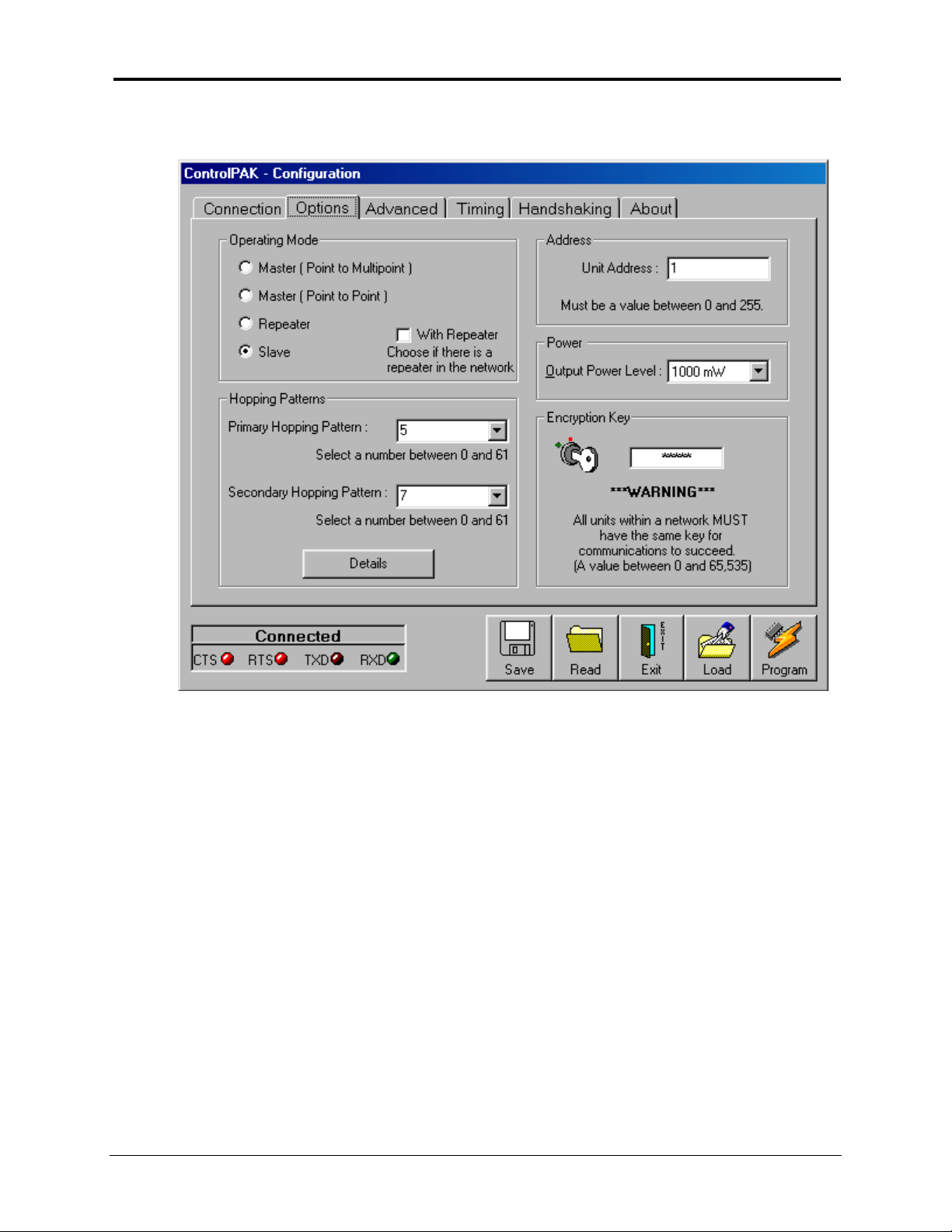
6.3.6 Configuration - Radio Options
6.3. 7 Outp ut Po wer Select ion
The O utp ut Pow er Level det ermines at what power the
’s sensitive receiver can operate with very low pow er levels, so it is r ecommended that the lowest
900
power necessary is used; usi ng excessive power contributes to unnecessary
The allowable set t i ngs are:
1 mW
10 mW
100 mW
1000 mW
COMMPAK-900
18
transmits. The
“RF pollution
”.
COMMPAK-
Page 27

I deally, y ou s hould t est the communications performa nce betw een units st arting f rom a low power level
and working upward until the RSSI is sufficiently high and a reliable link is established. Although the
conditions will vary widely between applications, typical uses for some of the settings are described
below:
Power Use
1 mW
10 mW
100 mW
1000 mW
(1 W)
For i n-buildin g use, typically provides a link up t o 300 feet on
the same floor or u p/down a level. Outdoor s, distances of 1 0
km can be achieved if high-gain (direction al) antennas are
placed high above ground lev e l and are in direct line-of- sight .
200-500 ft indoors, 8-15 km * out doors.
400-800 ft indoors, 15-2 5 km* outdoors.
Typically provides communi cati ons up to a distance of 1000
feet or more i n-buildin g on the sa m e floor or up/dow n a few
lev els, dep endin g on building construction (wood, concret e,
steel , etc.). In ideal line-of- sight condit ions, up to 30 km* or
more can be achieved. Not e that only an an tenna wi th a gain
of no more than 6 dBi may be used.
viol ation of FCC rule s
. See IMPORTANT warning below.
Any higher is a
* These outdoor dist ances ass ume antennas are mounted at least 100 ft above ground
level
IMPORTANT:
FCC Regulations allow up to 36 dBi effective radiated power (ERP). Therefore, the sum of the
transmitted pow er ( in dBm), t he cabling loss and the antenna gain cannot exceed 36 dBi.
1 mW = 0 dBm
10 mW = 10 dBm
100 mW = 20 dBm
1000 mW = 30 dBm
For example, when transmitt ing 1 Watt (30 dBm), t he antenna gain cannot exceed 36 - 30 = 6 dBi.
If an antenna with a gain h igher than 6 dBi wer e to be used, the power sett ing must be adjust ed
appropriately.
Encom Wireless Data Solutions Inc. limits the
COMMPAK-900
’s transmitted pow er to 100mW
for all units purchased wit h antennas wit h gain above 6dBi.
19
Page 28
6.3.8 Hopping Patterns
Several SCADA Systems can operate in one area by selecting a specific Hopping Pattern for
•
each syst em.
Also some of the Hopping Patterns notch out par t of the Spread Spect r um f r equency band, w hich
•
may eli minate i nterference in some cases.
The Secondary Hopping Patt er n only applies to r adios that are c onfigured as Repeater s.
•
Click on the Details button for further information.
•
6.3.9 Unit Address
Point to Multipoint System
This address is used only for radio diagnost ics sof t ware, which is currently being developed.
•
All Re motes will ha ve a s p e c ific Un it Address that w ill b e used b y the Mas ter radio f o r Diagnostics
•
Polling.
Point to Point System
This address is used by the Master t o indicate the address of t he radio it will c o mm u nic a te w ith.
•
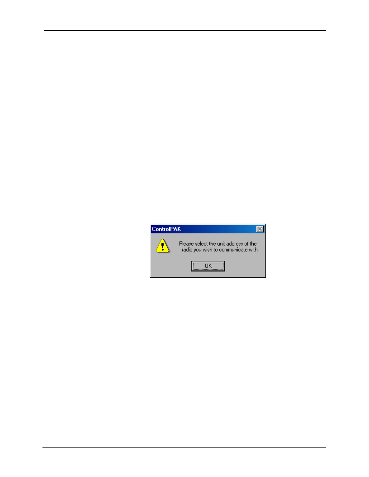
When you select the Operating Mode – M aster (Point t o Point), the message below w ill a p p ea r.
•
The Slave radio must have the same address as t he one entered in the Master r adio.
•
This mode of operation is typically used for file transfer and offers more secure and robust
•
operation.
20
Page 29

6.3.10 Encryption Key
This parameter allows you to enter a key value used by
ControlPAK
for encryption of the data.
The Encryption Key can only be read f rom a
radio. This allows a greater level of security but the following items and procedures must be followed
when enteri ng a User defi ned Encryption Key and reco nfiguring radios progra mmed w ith a User def ined
Encrypt io n Key:
Create the Configuration files by configuring and program ming t he radios a nd saving t he configuratio ns to
specific files. ie; M aster, Repeater, Slave The initial entry of the Encryptio n Key requires the User to enter
the Encryption Key as indicated in t he
Encryption Key the radio ca n be programmed direct ly f r om
subsequent configuratio n parameter changes to any of the radios with this user defi ned Encryptio n
ALL
Key must be made by
applicable configuration file for the radio. Now all required configuration changes for the radio can be
made.
the new configuration and
Save
I f the procedure outlined above is not followed the user defined Encryption Key can be lost.
"
When the radio confi guration is read, t he Encryption Key is read as non-character s and t he
ControlPAK
change and do not re-enter your Encryptio n Key the
will be programmed to the radio. However, if you follow the procedure abo ve the correct
Encryp tio n K e y will be r ead from the Configuration file.
Connecting
default Encryption Key is then entered on screen. If you make a configuration
the radio to the
ControlPAK
ControlPAK
Program
the radio
Configuration file it cannot be read from the
software. For this initia l entry of t he user defi ned
ControlPAK
ControlPAK
ControlPAK
.
software and then
default Encryption Key
Reading
the
21
Page 30
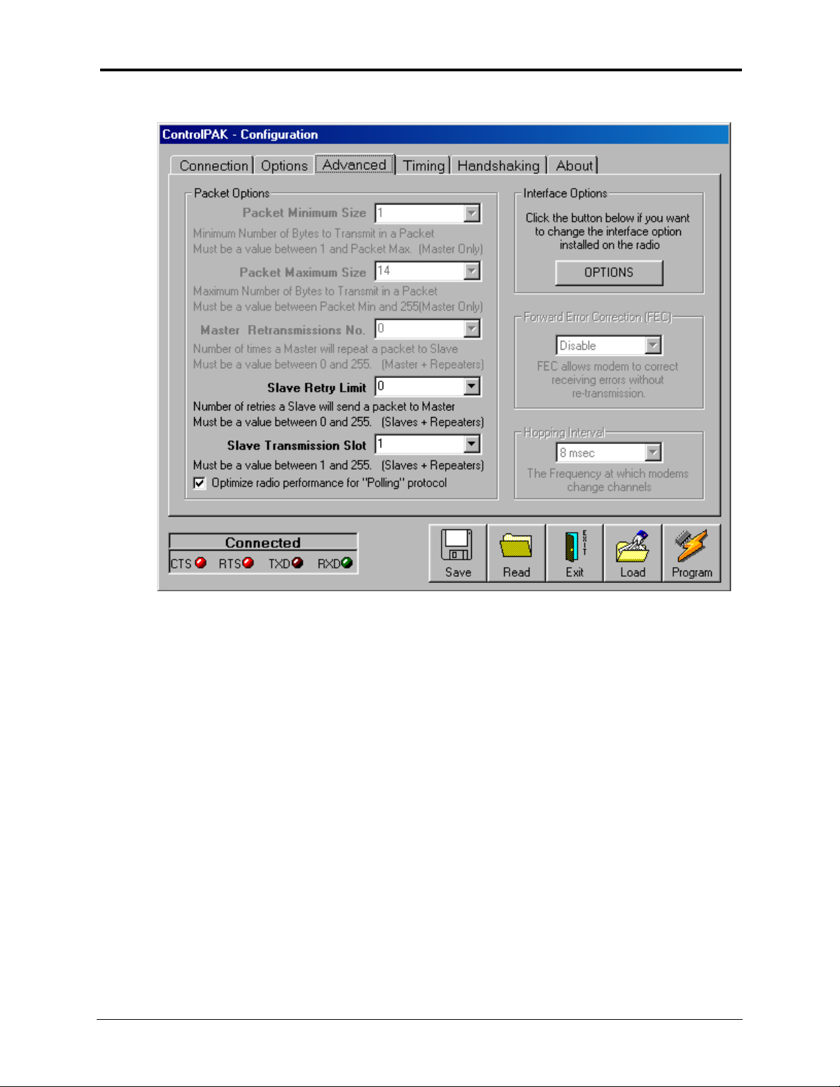
6.3. 11 Con f igu rat ion – Advanced Radio Op t io ns
Packet Minimum and Maximum Size
Master only. The connected device must transmit at least the number of bits indicated by the packet
minimum size bef ore t he r a d io will t ransmit.
Master Ret ransmiss ions
transmit each message to the Slave radios. The Repeater radio does not use this parameter when
transmitting to the Master radio.
Slave Retry Limit
and this parameter defi nes the number of times the Slave and Repeater radios will r etr ans mit t heir data.
If the limit is reached and the Slave or Repeater radio has not recei ved an acknowledgeme nt the data is
discarded.
Slave Transmission Sl ot
made up of 255 timeslots for the Slave to respond. For SCADA polling applicatio ns the Slaves should all
respond in timeslot 1. When you check ‘Optimize radio perf or ma nce for “ Polling pr ot oc ol”’
sets t his parameter to 1.
Forward Error Correction (FEC)
additional method of err or correct ion is used i n your system.
Hopping Interva l
tha n the de fa ult of 8 t he overal l thro ughput will dec rease .
size based on the Hopping Interval a nd whet her FEC is selected.
– The Sla ve and Repeater r adios must receive an acknowledgeme nt from the Master
– This parameter is set in the Master r adio only. If the Hopping Interval is set low er
– This defines t he number of times the Master and the Repeater radios will
– When the Master radio has transmitted it s dat a, it then provides a time period
– This defines t he size of the packets tr ansmit ted and is set in the
ControlPAK
– This parameter is set in the Master only and determines if this
ControlPAK
will rest rict t he maxim um pack et
22
Page 31
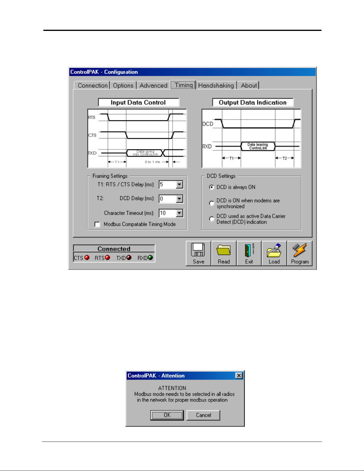
6.3.12 Configuration –Radio Timing Parameters
Framing Settings
Sets the delay between the reception of RTS from the device connected to t he
T1.
•
radio and the acti vation of CTS by the radio. This only applies if Hardwar e Handshaking is
900
selected. This parameter is also used to set the time period from when the
radio receives data from another r adio a nd outputs this dat a t o t he connected device.
Sets the time that DC D remai ns acti vated after recept ion of the data packet.
T2.
•
Character Timeout.
•
before r etrying
Modbus Compatible Timing Mode.
•
configures t he timing parameter s
Sets the amount of time the
When this mode is selected
23
COMMPAK-900
radio waits for a data packet
ControlPAK
COMMPAK-
COMMPAK-900
automatically
Page 32
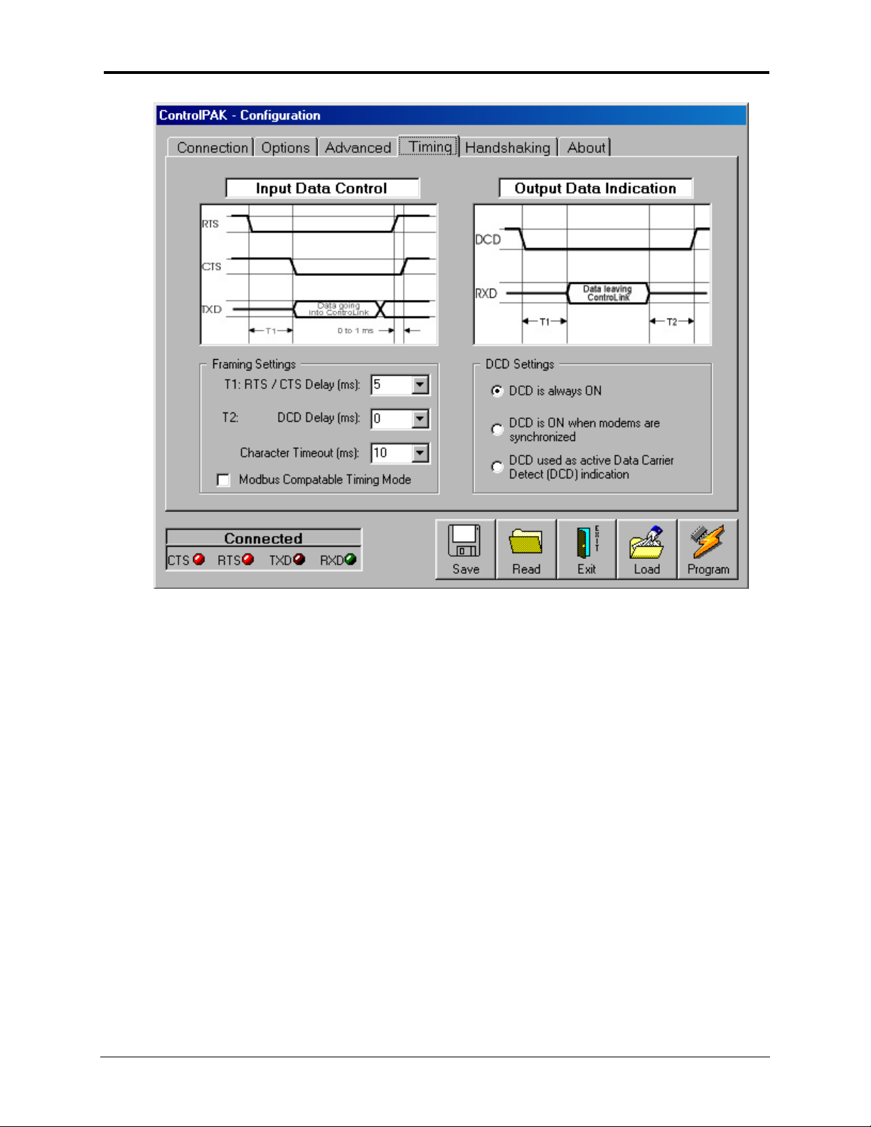
DCD Settings
DCD is always ON.
•
devices that require a consta nt DCD signa l to indic a te t he r a dio is c onnected.
This setting is used when connecting to the
COMMPAK-900
radio to
DCD is ON when modem s are syn c hronized.
•
to your equipment that the radio link has dropped out.
DCD used as a ctive DCD ind ic atio n.
•
Configures DCD for standard data detection operation.
This setting can be used t o provide an indicat io n
24
Page 33
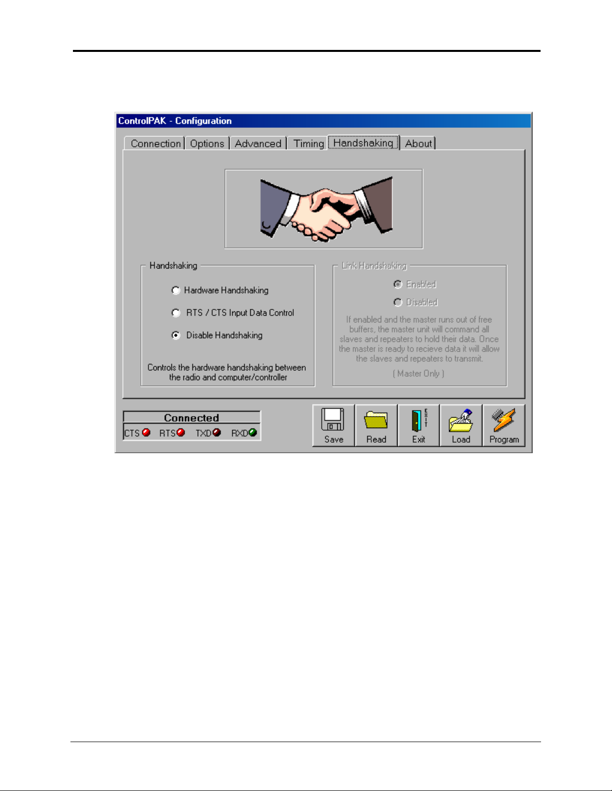
6.3. 13 Con f igu rat ion –Radio Han dshaking Parameters
Handshaking
Hardware Handshaking.
•
two DTE devices, such as computer s. An example application wo uld be file transfers. This mod e
of handshaking indicates the status of the Receive Buffer level in each radio. Only the CTS
signal is used for ea
RTS/CT S Input Data Cont rol
•
the appropriate timing parameters must be set on the
selected, these values will be automatically selected by
configurable.
This setting is typically used for Point-to-Point communication between
. Enables RTS/CTS input data f raming. If this f eature is enabled,
TIMING
25
page. If MODBUS mode is
ControlPAK
and are not user
Page 34
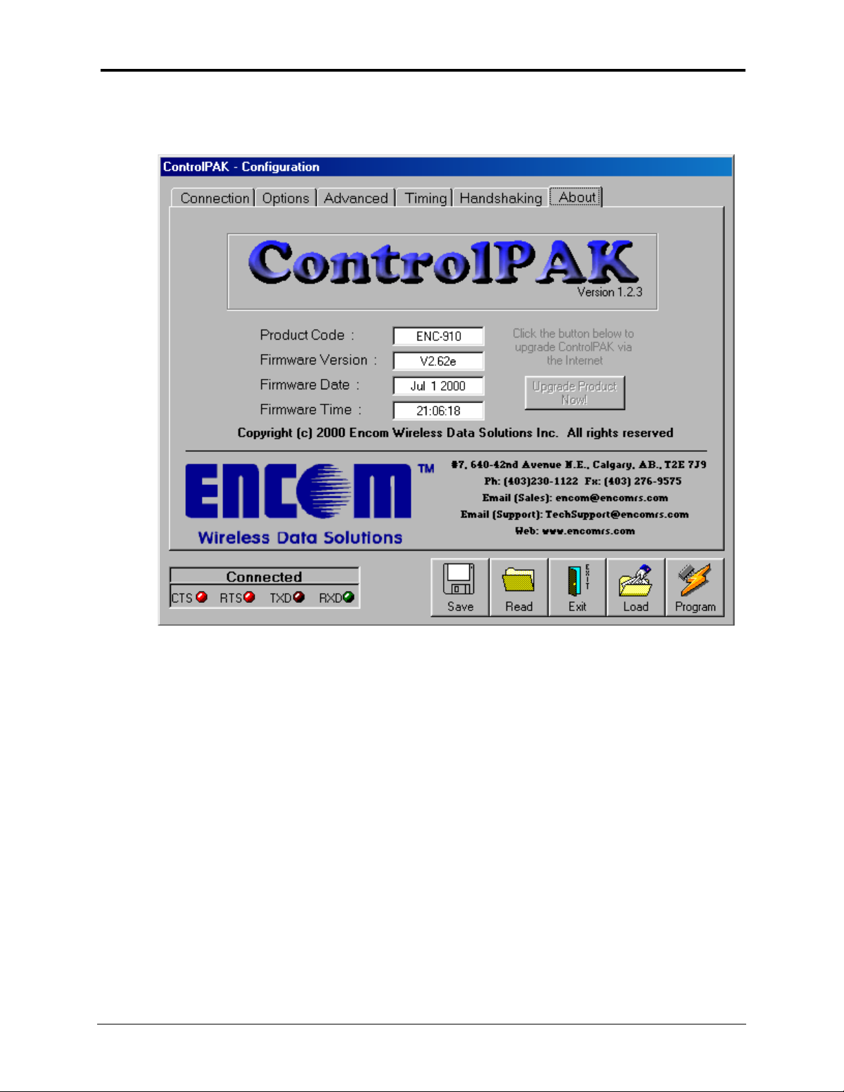
6.3. 14 Con t rolPAK V ersion
The about page allows t he user t o view the versio n details of
wireless transceiver. This information can be extremely useful when troubleshooting and service are
required.
26
ControlPAK
and the
COMMPAK-900
Page 35

6.3 .1 5 R a dio Progr a m m ing
Whe n you have completed the selectio n of the parameters required f or reconfiguring yo ur r adio,
•
click on the PROGRAM button.
If you do not Program the radio with the new configuration, a message will appear when yo u
•
Disconnect or Exit t he program.
6.3 .1 6 Sa v ing Configurat ions To File s
Configuratio ns may be saved to a file desig nated by the User.
•
Click on the
•
The
•
•
ControlPAK
Appending File s.
related configurations in a single file. For example, the MAIN SCADA co nfigurations, Master,
Local and Repeater may all be saved in a single file designated M AIN SCADA. The initial file is
created when the first configuration is saved. This file can then be appended by selecting it,
when saving the additional configurations. When you select an existing file, a message will
appear aski ng if you would like to append the existing file.
button.
Save
sof tw are will guide you through the Sa ve p r o c e dure.
ControlPAK
allows you to append an existing file, in order for you to save
6.3.17 Loading Configurations From Files
The
•
Click on the
•
Select the r e quired file t he Conf iguration is sa ved in.
•
Follow the previously outlined procedures for Progr amming t he radio.
•
ControlPAK
Conf iguratio n f rom a f ile .
softw are must be connected t o a radio as outli ned in Sectio n 5.3.4, to load a
button to load co nfigurat io ns from an existing f ile.
Read
27
Page 36

7.
COMMPAK-900 Technical Specifications
7.3.1 Electrical/Environment Specifications:
Power Requirement
Power Consumptio n 450mA at 1W Tr ansmit, 250mA Recei ve a nd 10uA Sleep Mode
Operatin g
Environment
Memory Non-vola ti le c onfigura ti on mem ory
Operat ional Modes Point-to-Point, Point-to-Multipoint and Peer-to-Peer
Temperat ure: - 34 t o +72°C, Humi dity: 5 to 95% non-condensing
8 to 30 VDC
7.3.2 Mechanical Specifications:
Dimensions
(WxDxH)
Enclosure Mater ial Milled alumi num, black, baked pow der coat f inish
Serial Data
Connector
Antenna Connector Rever s e p o la r ity TNC male
Power Connector
90mm(3.56 inch) x 101mm (4.38 inch) x 42mm(1. 69 inch)
Excluding co nnectors and mounti ng bracket .
9-pin female D-sub
Molex 4.2mm (0.165 inch) pitc h Mini-Fit, Jr . Plug
(72 inch power cable included)
7.3. 3 Serial Data Interface Specificat ion s:
Data Interface
Signals Sig. GND, TX D, RXD, RT S, CTS, DTR#, Data Active DCD
Data Format 1200 to115,200 bps. 7 or 8 Data bit s with Odd, Even or No Parity.
Bandwidth
Data Transmission
• TXD and RXD are sti ll suppor t ed in RS232 format (only in progr am ming m ode) with t hi s opti on i nst all ed.
# In Sleep Mode, the radio is reacti vat ed by the DTR signal with at least a 30msec warm up time
Asynchrono us RS-232,
Optional 2/4-wir e RS485*
115,200 bps, uncompressed half - duple x. Approximately 100 kbps
sustained in intellige nt asymmetrical full-duple x tr ansmission mode.
Key-by data or RTS data input framing with programmable RTS/CTS
time delay.
.
7.3.4 Radio Specifications:
Technology Frequency Hopping Spr ead Spect r um
Operat ing Freq uency 902 – 928 M Hz
Hopping Patter n
System Gain 135 dB
Receive Se nsitivity - 106 dBm @ 10-6 BER
Output Power 1mW, 10mW, 100mW, 1W ( user-select able)
Error Detection CRC-16 with auto- ret r a nsm it
Encryption Up to 65535 combinations
Diagnostics
3 LED bar graph to indicate RSSI a nd RF Link quality,
Dedicated LEDs for TXD and RX D display.
62 pseudo-random
28
 Loading...