


ENCOM PULSE Link
USER MANUAL
Toll Free: 1-800-617-3487
Worldwide: (403) 230-1122
Fax: (403) 276-9575
Web: www.encomwireless.com
For ENCOM PULSE Link Version 2.2.6 © 2012-2015 Encom Wireless Data Solutions Inc.


Table of Contents
ENCOM PULSE Link
USER MANUAL
Chapter 1: Introduction
................................................................................................................................... 5Compatible ENCOM Radios
Chapter 2: Installation
................................................................................................................................... 6System Requirements
................................................................................................................................... 7Downloading the PULSE Link Software
................................................................................................................................... 8Installing the PULSE Link Software
Chapter 3: Using ENCOM PULSE Link
................................................................................................................................... 15Running ENCOM PULSE Link
................................................................................................................................... 15Connecting to a Radio
.......................................................................................................................................................... 16Connecting to a PULSE Radio
.......................................................................................................................................................... 18Connecting to an iPULSE Radio
.......................................................................................................................................................... 21Connecting to a 5000 Series Radio
......................................................................................................................................................... 24Setting the 5000 Series Radio Product Code
................................................................................................................................... 28User Interface
.......................................................................................................................................................... 29Menu Bar
......................................................................................................................................................... 30File Menu Functions
......................................................................................................................................... 30Exit
......................................................................................................................................................... 31Radio Menu Functions
......................................................................................................................................... 31Upgrade
................................................................................................................................... 32Upgrading a PULSE Radio
................................................................................................................................... 36Upgrading an iPULSE Radio
................................................................................................................................... 40Upgrading a 5000 Series Radio
......................................................................................................................................... 45Recover
................................................................................................................................... 46Recovering a PULSE Radio
................................................................................................................................... 56Recovering a 5000 Series Radio
......................................................................................................................................... 64Restore to Factory Defaults
......................................................................................................................................................... 65Tools Menu Functions
......................................................................................................................................... 65Demo Mode
......................................................................................................................................................... 68Help Menu Functions
......................................................................................................................................... 68Topics
......................................................................................................................................... 68About
.......................................................................................................................................................... 69Status Bar
......................................................................................................................................................... 71Search for iPULSE Radios Button
......................................................................................................................................................... 72Detect USB Devices Button
......................................................................................................................................................... 73Connect to serial device button
......................................................................................................................................................... 74USB Serial Port Settings Button
......................................................................................................................................................... 75Status Information Panel
.......................................................................................................................................................... 78Options List
.......................................................................................................................................................... 79Settings Panel
......................................................................................................................................................... 80Identification Tab
......................................................................................................................................................... 83Wireless Tab
......................................................................................................................................................... 87Netw ork Tab
5
6
15
Page 3
© 2012-2015 Encom Wireless Data Solutions Inc.For ENCOM PULSE Link Version 2.2.6

......................................................................................................................................... 91P-MP Master Mode
......................................................................................................................................... 93P-MP Remote Mode
......................................................................................................................................... 95TCP Server Mode
......................................................................................................................................... 97TCP Client Mode
......................................................................................................................................... 99TCP Client & Server Mode
......................................................................................................................................... 101VCOM UDP Mode
......................................................................................................................................................... 102Serial Port Tab
......................................................................................................................................... 103FSK Radio Serial Port Settings
......................................................................................................................................... 106RS-232 Radio Serial Port Settings
......................................................................................................................................... 110iPULSE Radio Serial Port Settings
......................................................................................................................................................... 113Advanced Tab
......................................................................................................................................................... 117Export Button
......................................................................................................................................................... 118Import Button
......................................................................................................................................................... 120Save Button
......................................................................................................................................................... 120Reset Button
.......................................................................................................................................................... 121Signal Strength Panel
......................................................................................................................................................... 122Signal Strength Toolbar
......................................................................................................................................................... 123Signal Strength Meter
......................................................................................................................................................... 124Using the Signal Strength Panel
.......................................................................................................................................................... 126Poll Test Panel
......................................................................................................................................................... 127Poll Test Toolbar
......................................................................................................................................................... 128Poll Test Report
.......................................................................................................................................................... 131Spectrum Scan Panel
......................................................................................................................................................... 132Spectrum Scan Toolbar
......................................................................................................................................................... 133Spectrum Scan Graph
.......................................................................................................................................................... 135iPULSE Radios Form
......................................................................................................................................................... 137Changing the IP Address of an iPULSE Radio
......................................................................................................................................................... 139Resettting an iPULSE Radio
......................................................................................................................................................... 141Refreshing the iPULSE Radio List
......................................................................................................................................................... 142View ing or Changing the Settings of an iPULSE Radio
ENCOM PULSE Link
USER MANUAL
Chapter 4: PULSE Radio Network Example
................................................................................................................................... 147PULSE Master (0) Configuration
................................................................................................................................... 148PULSE Remote (1) Configuration
................................................................................................................................... 149PULSE Remote (2) Configuration
................................................................................................................................... 150PULSE Repeater (3) Configuration
................................................................................................................................... 151PULSE Repeater (4) Configuration
................................................................................................................................... 152PULSE Remote (5) Configuration
................................................................................................................................... 153PULSE Repeater (6) Configuration
................................................................................................................................... 154PULSE Remote (7) Configuration
................................................................................................................................... 155PULSE Remote (8) Configuration
144
Page 4
© 2012-2015 Encom Wireless Data Solutions Inc.For ENCOM PULSE Link Version 2.2.6
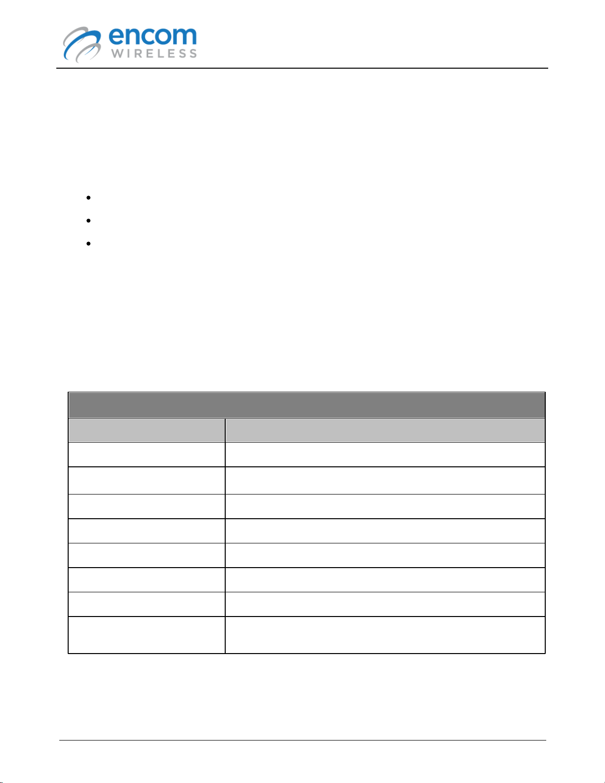
ENCOM PULSE Link
ENCOM 900 MHz Serial Radios
Radio Model
Description
iPULSE R
900 MHz rack mount serial radio with Ethernet interface
iPULSE S
900 MHz shelf mount serial radio with Ethernet interface
PULSE 2070
900MHz 2070 style radio
PULSE C
900MHz shelf mount FSK radio
PULSE CR
900MHz rack mount FSK radio
PULSE S
900MHz shelf mount serial radio
PULSE SR
900MHz rack mount serial radio
5000 series adapter card
PULSE adapter card for 5000 series radios (5100R, 5100S,
5170, 5171, 5200R, 5200S, 5270)
USER MANUAL
Chapter 1: Introduction
This guide describes the operation of the ENCOM PULSE Link radio configuration utility. ENCOM
PULSE Link is a Microsoft Windows based application that is used to set up networks of ENCOM
900 MHz serial and FSK radios.
With ENCOM PULSE Link, you can:
Configure your ENCOM 900 MHz radios using a friendly user interface
Optimize the performance of your 900 MHz wireless network
Diagnose network and communication issues
This guide contains instructions, suggestions and information that will help you set up your radios
and achieve optimal performance of your equipment.
Compatible ENCOM Radios
The following ENCOM radios are compatible with the ENCOM PULSE Link software:
Page 5
© 2012-2015 Encom Wireless Data Solutions Inc.For ENCOM PULSE Link Version 2.2.6

ENCOM PULSE Link
USER MANUAL
Chapter 2: Installation
System Requirements
ENCOM PULSE Link was created to run on a wide variety of computers, from netbooks that can be
used by field personnel to high-powered, multi-monitor workstations used in the network operations
center.
In order to run ENCOM PULSE Link, your computer must meet the following minimum
requirements:
Windows XP SP3, Vista, Windows 7 or Windows 8 operating system
Microsoft .NET Framework 4
2 GB RAM
1 GB free hard drive space
Video card with a minimum 1024 x 720 resolution
Page 6
© 2012-2015 Encom Wireless Data Solutions Inc.For ENCOM PULSE Link Version 2.2.6

ENCOM PULSE Link
Email:
support@encomwireless.com
Phone:
1-800-617-3487 (ext. 223)
1-972-885-5170
USER MANUAL
Downloading the PULSE Link Software
ENCOM PULSE Link is available for download from the ENCOM Wireless website. To download
ENCOM PULSE Link:
1. Using a web browser, go to the ENCOM Software Download Registration page on the
ENCOM web site at:
http://www.encomwireless.com/downloads/software
2. Enter the requested information, and make sure that you select Pulse Link in the Software
Required field. Then click on the Send button.
3. A confirmation email will be sent to the email address you entered in the registration page.
4. Follow the instructions in the email you received to download the ENCOM PULSE Link setup
program to your computer.
If you have trouble downloading or installing PULSE Link, please contact ENCOM technical support,
using any of the following options:
Page 7
© 2012-2015 Encom Wireless Data Solutions Inc.For ENCOM PULSE Link Version 2.2.6
Installing the PULSE Link Software
Although ENCOM PULSE Link will run under a standard user account, you will need
administrator privileges to install the application. Please contact your IT department
if you are unable to install PULSE Link due to account restrictions.
After downloading ENCOM PULSE Link:
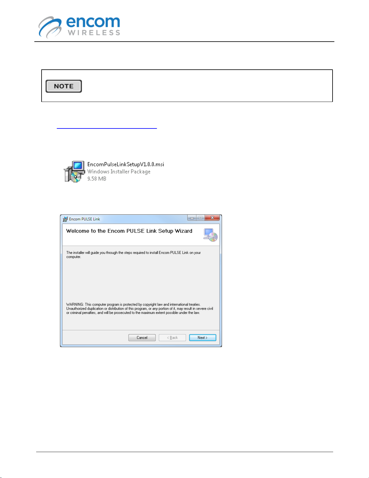
1. Double click the EncomPulseLinkSetupVx.x.x.msi file to start the installation process
(where x.x.x is the PULSE Link version number).
2. The ENCOM PULSE Link Setup Wizard will appear and will guide you through the
installation of the application to your computer
ENCOM PULSE Link
USER MANUAL
Click Next to proceed.
Page 8
© 2012-2015 Encom Wireless Data Solutions Inc.For ENCOM PULSE Link Version 2.2.6
ENCOM PULSE Link
USER MANUAL
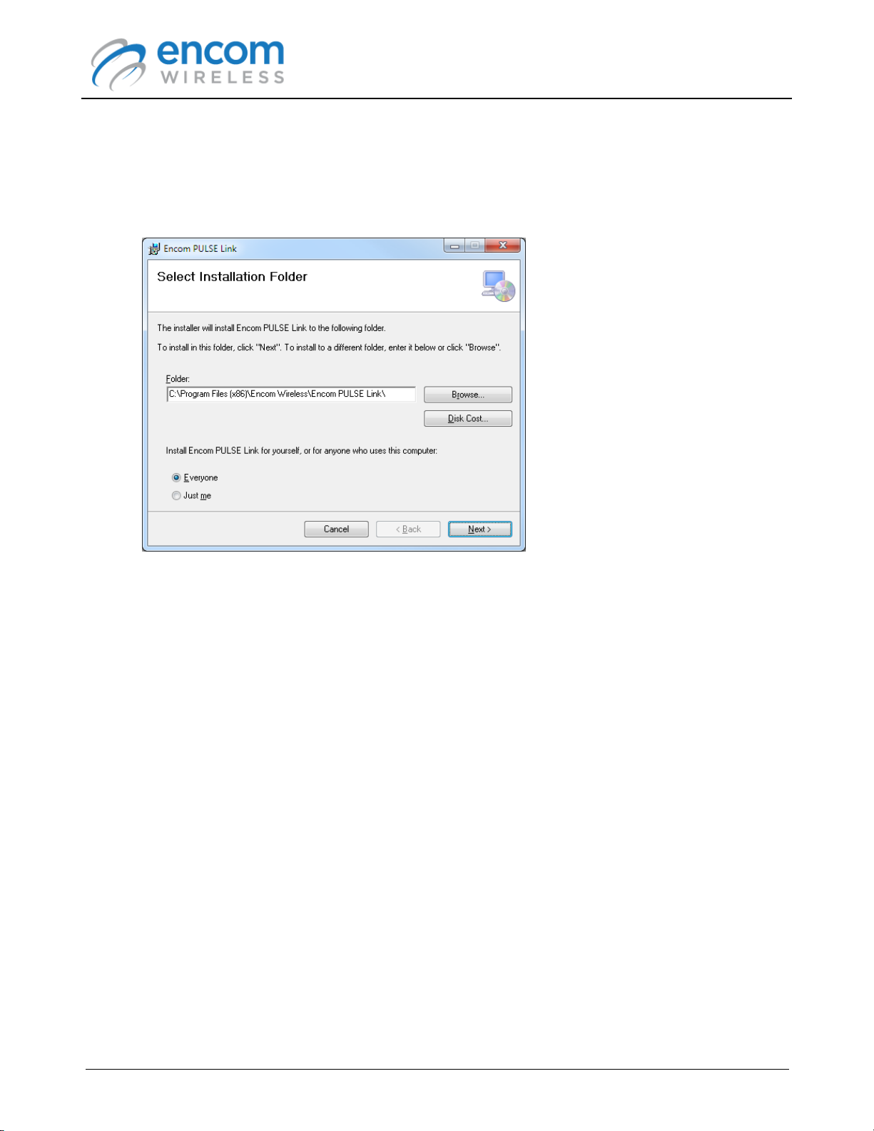
3. Select the folder on your computer where you would like ENCOM PULSE Link to be installed.
You can also instruct the setup wizard to install PULSE Link for all users or the currently
logged in user. Note that in both cases, you need to have administrator privileges in order to
successfully install the application.
Click Next to proceed.
Page 9
© 2012-2015 Encom Wireless Data Solutions Inc.For ENCOM PULSE Link Version 2.2.6
ENCOM PULSE Link
USER MANUAL
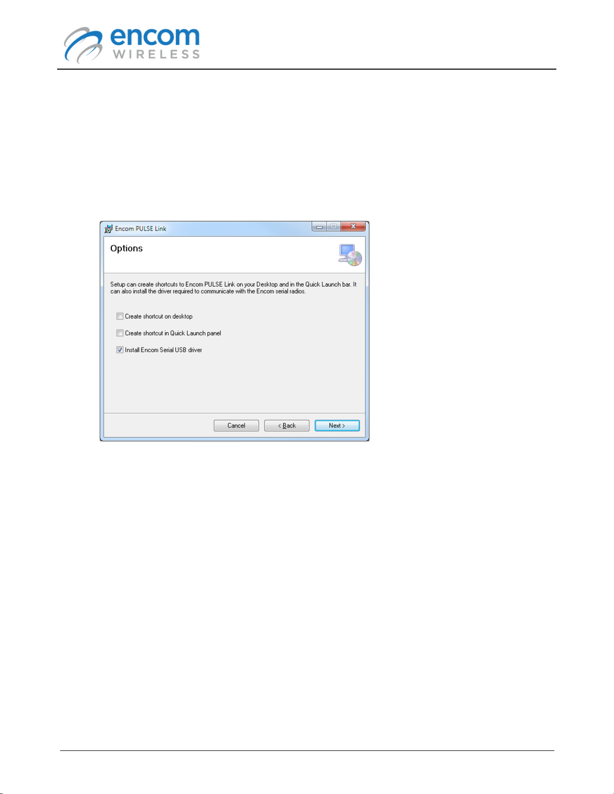
4. Select the desired options. Note that a shortcut will always be created under Programs ->
Encom -> PULSE Link in the Windows Start menu. The Desktop and Quick Launch
shortcuts simply provide alternate means to access the application.
If this is the first time that you install ENCOM PULSE Link, ensure that the Install Encom
Serial USB Driver option is checked. The setup program will pre-install the appropriate
driver files on your computer, and the driver will be automatically installed when you connect
to a 900 MHz serial radio with the USB cable. Leaving this option checked won't affect a driver
that has already been installed.
Click Next to proceed.
Page 10
© 2012-2015 Encom Wireless Data Solutions Inc.For ENCOM PULSE Link Version 2.2.6
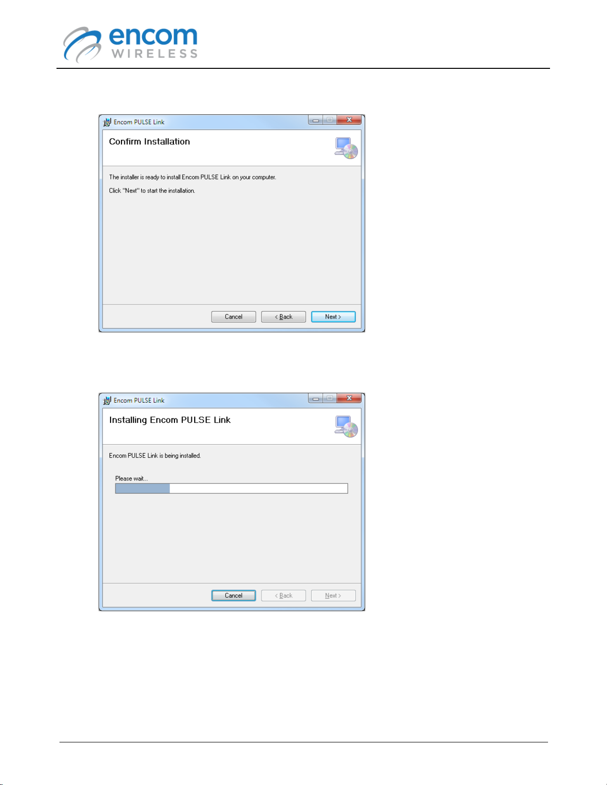
5. The final confirmation page is shown.
ENCOM PULSE Link
USER MANUAL
Click Next to proceed.
6. ENCOM PULSE Link will be installed on your computer.
Enter the appropriate administrator account credentials if you are prompted to do so.
Page 11
© 2012-2015 Encom Wireless Data Solutions Inc.For ENCOM PULSE Link Version 2.2.6
ENCOM PULSE Link
USER MANUAL
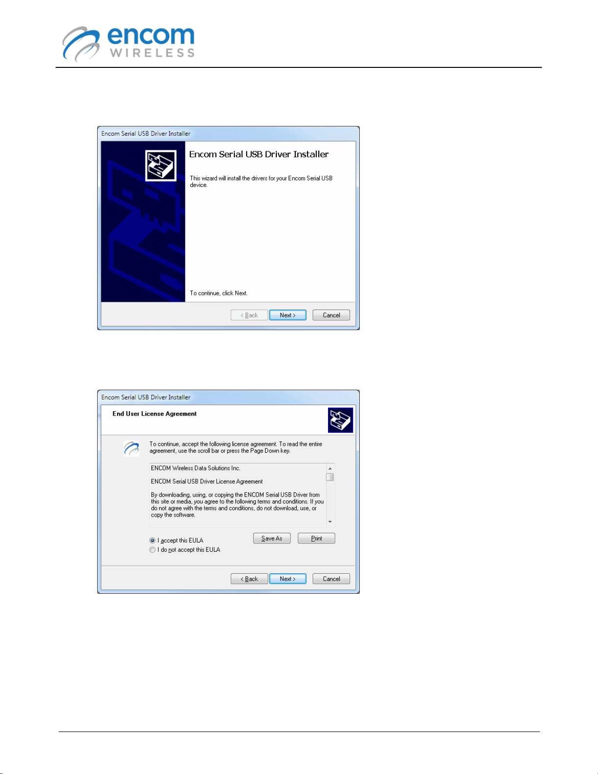
7. If you checked the Install Encom Serial USB Driver option, the driver installation wizard will
be displayed.
Click Next to proceed.
8. The driver license page is shown:
Select the I accept this EULA option, and click Next to proceed.
Page 12
© 2012-2015 Encom Wireless Data Solutions Inc.For ENCOM PULSE Link Version 2.2.6
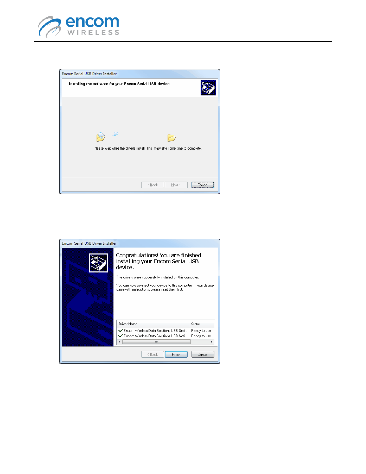
9. The ENCOM Serial USB drivers will be installed on your computer.
ENCOM PULSE Link
USER MANUAL
During the installation process, you may be prompted for permission to install the drivers.
Answer Yes or OK to all prompts.
10.When the driver installation is completed, click Finish to exit the driver installation wizard.
Page 13
© 2012-2015 Encom Wireless Data Solutions Inc.For ENCOM PULSE Link Version 2.2.6
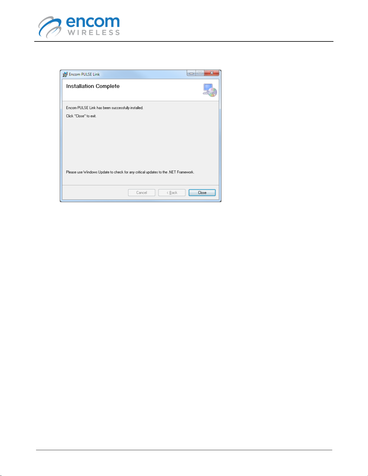
11.Finally click Close to exit the PULSE Link installation wizard.
ENCOM PULSE Link
USER MANUAL
12.ENCOM PULSE Link is now installed on your computer.
Page 14
© 2012-2015 Encom Wireless Data Solutions Inc.For ENCOM PULSE Link Version 2.2.6

Chapter 3: Using ENCOM PULSE Link
Running ENCOM PULSE Link
You can run ENCOM PULSE Link using any of the following methods
Select Programs -> Encom -> PULSE Link -> Encom PULSE Link from the Windows Start
menu
If you requested that a PULSE Link shortcut be installed on your desktop, you can start
PULSE Link by double-clicking the desktop icon:
ENCOM PULSE Link
USER MANUAL
If you requested that a PULSE Link shortcut be installed in the QuickLaunch panel, you can
start PULSE Link by clicking on the QuickLaunch icon:
Connecting to a Radio
ENCOM PULSE Link supports two families of 900 MHz serial radios:
ENCOM PULSE radios (configured via USB interface)
ENCOM iPULSE radios (configured via Ehthernet interface)
ENCOM 5000 series adapter boards (configured via Serial interface)
To connect to a radio, follow the procedures found in the following topics:
Connecting to a PULSE Radio
Connecting to an iPULSE Radio
Connecting to a 5000 Series Radio
Page 15
© 2012-2015 Encom Wireless Data Solutions Inc.For ENCOM PULSE Link Version 2.2.6
Connecting to a PULSE Radio
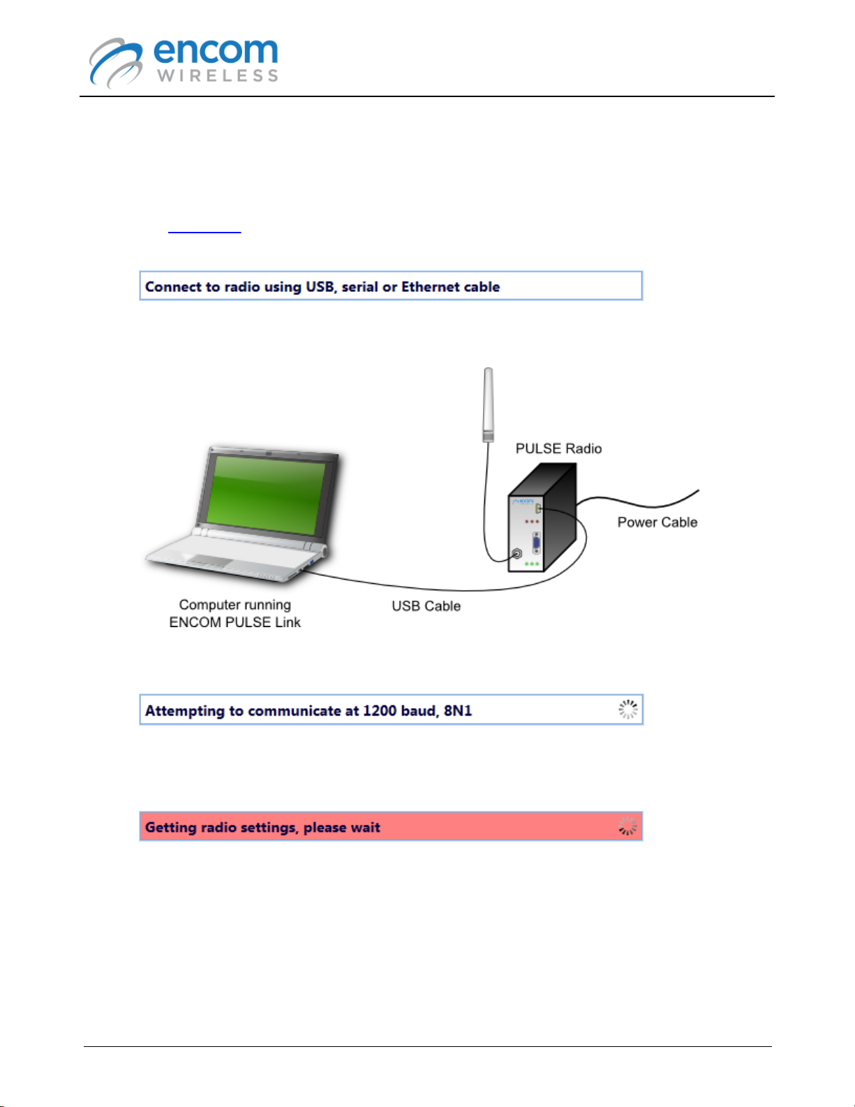
To connect to an ENCOM PULSE radio, follow the procedure listed below:
1. Run the ENCOM PULSE Link application on your computer.
2. The Status Bar at the top right-hand corner of the application's window will prompt you to
connect to a radio.
3. Power the PULSE radio with the provided wall mount power adapter, and then connect the
radio to your computer with the included USB cable.
ENCOM PULSE Link
USER MANUAL
4. ENCOM PULSE Link will detect the radio and attempt to communicate with it.
5. When PULSE Link is able to communicate with the radio, it will automatically retrieve its
configuration settings.
Note that when the status bar is red, you should not disconnect the USB cable from the radio,
nor should you remove power from the radio. Doing so could prevent the radio from being
able to communicate properly over the serial port (or the FSK port for FSK radios). If this
happens, you may have to use PULSE Link again to restore the radio's configuration.
Page 16
© 2012-2015 Encom Wireless Data Solutions Inc.For ENCOM PULSE Link Version 2.2.6
ENCOM PULSE Link
USER MANUAL
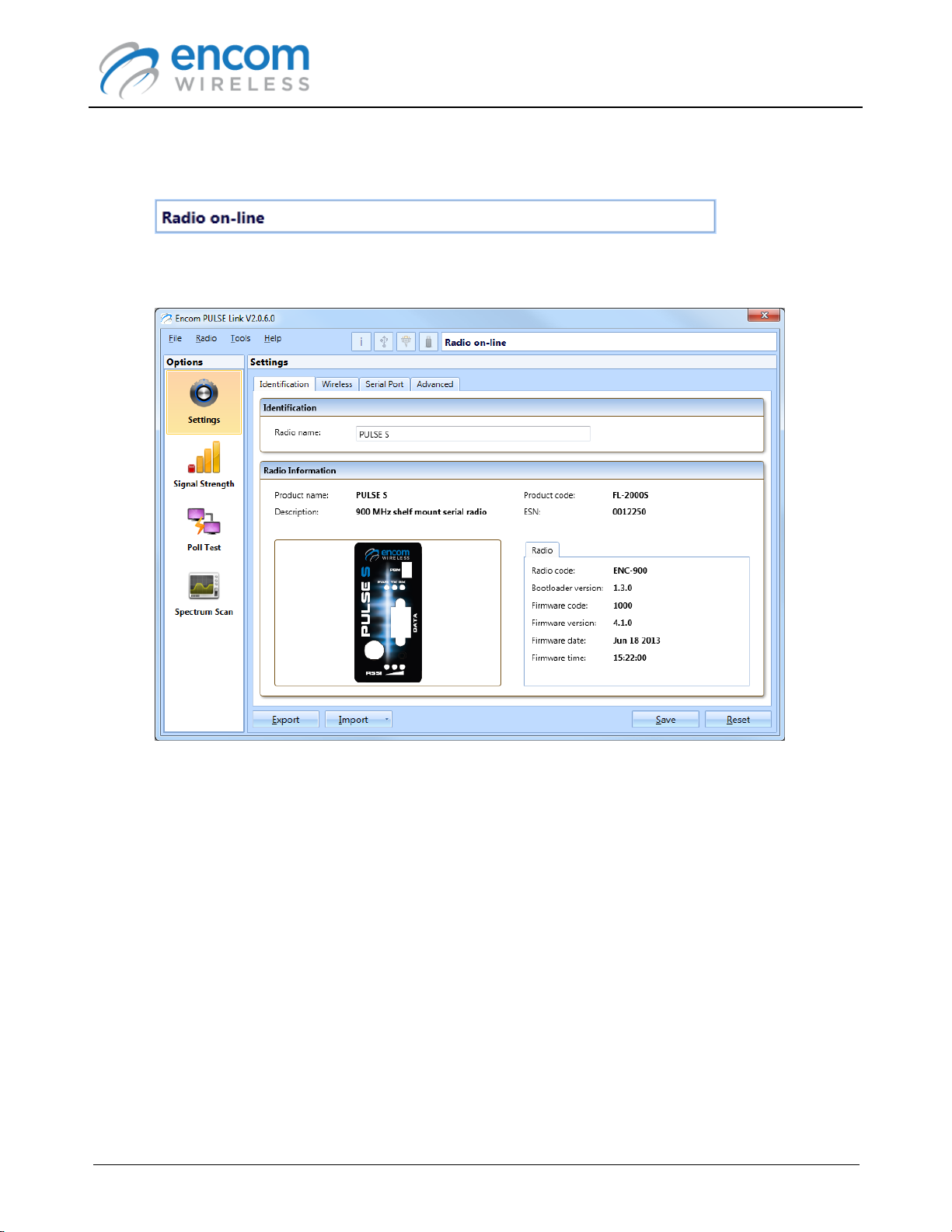
6. After the radio's configuration settings have been retrieved, the radio is shown as being online.
7. The radio configuration panel is displayed. At this point you can use ENCOM PULSE Link to
manage your radio.
Page 17
© 2012-2015 Encom Wireless Data Solutions Inc.For ENCOM PULSE Link Version 2.2.6
Connecting to an iPULSE Radio
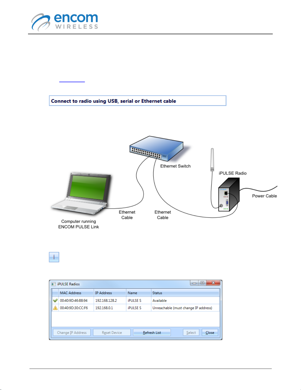
To connect to an ENCOM iPULSE radio, follow the procedure listed below:
1. Run the ENCOM PULSE Link application on your computer.
2. The Status Bar at the top right-hand corner of the application's window will prompt you to
connect to a radio.
3. Power the iPULSE radio with the provided wall mount power adapter, and then connect the
radio to your computer using an Ethernet cable.
ENCOM PULSE Link
USER MANUAL
4. Click the Search for iPULSE radios button at the left of the status bar.
5. The iPULSE Radios form is displayed.
While this form is visible, PULSE Link is actively searching for iPULSE radios. It will detect
Page 18
© 2012-2015 Encom Wireless Data Solutions Inc.For ENCOM PULSE Link Version 2.2.6
ENCOM PULSE Link
USER MANUAL
and list all iPULSE radios that are connected to your local network. It will NOT detect an
iPULSE radio if there is a router between the radio and the computer running the PULSE Link
application.
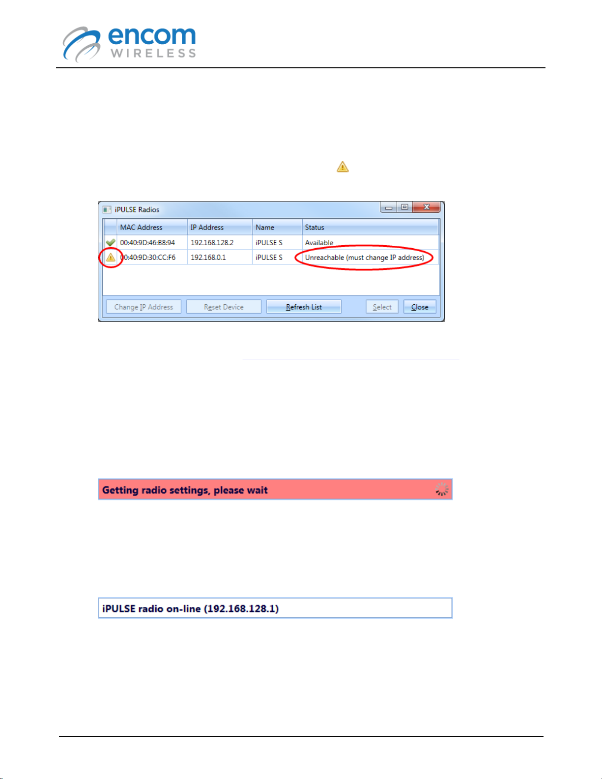
6. If you have just received your iPULSE radio from ENCOM, its default IP address may not be
compatible with your local network. In this case, a indicator is shown at the left of radio's
MAC Address, and the Status column indicates that you must change the radio's IP address.
In order to connect to a radio that is unreachable, you will have to change it's IP address to a
compatible value. Refer to the Changing the IP Address of an iPULSE Radio topic for more
information.
7. To connect to a radio, select the radio item in the radio list, and then click the Select button.
Alternatively, you can double-click the left mouse button on the radio item in the radio list.
8. The status indicator will briefly display a message while the radio's configuration settings are
retrieved.
Note that when the status bar is red, you should not disconnect the Ethernet cable from the
radio, nor should you remove power from the radio.
9. After the radio's configuration settings have been retrieved, the radio is shown as being online.
Page 19
© 2012-2015 Encom Wireless Data Solutions Inc.For ENCOM PULSE Link Version 2.2.6
ENCOM PULSE Link
USER MANUAL
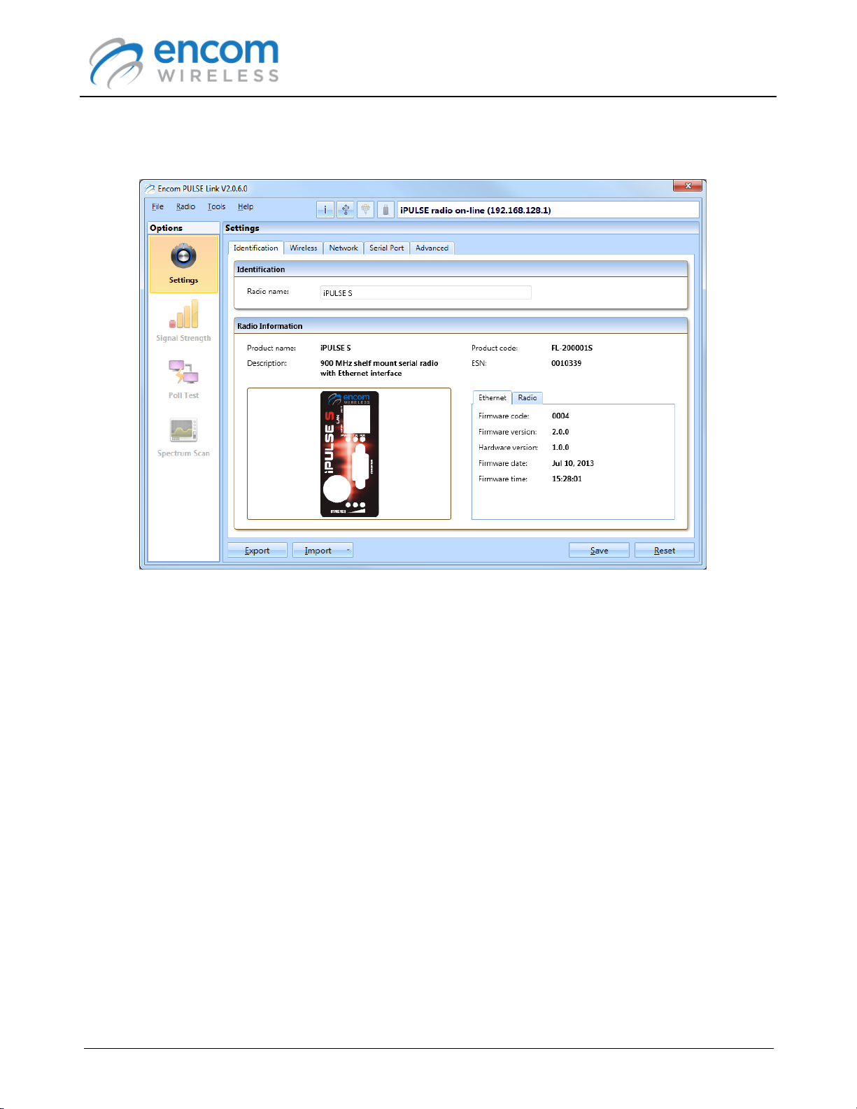
10.The radio configuration panel is displayed. At this point you can use ENCOM PULSE Link to
manage your radio.
Page 20
© 2012-2015 Encom Wireless Data Solutions Inc.For ENCOM PULSE Link Version 2.2.6
ENCOM PULSE Link
USER MANUAL
Connecting to a 5000 Series Radio
To connect to a 5000 series radio in which a 5000 series adapter card has been installed:
1. Run the ENCOM PULSE Link application on your computer.
2. The Status Bar at the top right-hand corner of the application's window will prompt you to
connect to a radio.
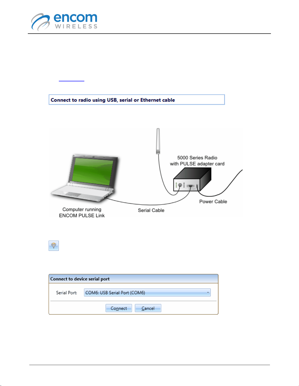
3. Power the 5000 series radio with the provided wall mount power adapter, and then connect
the radio to your computer using a serial or serial-to-USB adapter cable.
4. Click the Connect to serial device button at the left of the status bar.
5. The Connect to device serial port form is displayed.
6. Select the serial communications port to which the radio is connected, and then click the
Connect button.
Page 21
© 2012-2015 Encom Wireless Data Solutions Inc.For ENCOM PULSE Link Version 2.2.6
ENCOM PULSE Link
USER MANUAL
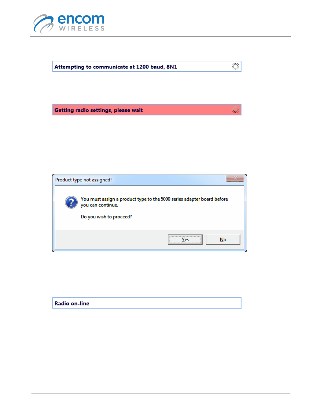
7. ENCOM PULSE Link will detect the radio and attempt to communicate with it.
8. When PULSE Link is able to communicate with the radio, it will automatically retrieve its
configuration settings.
Note that when the status bar is red, you should not disconnect the serial cable from the
radio, nor should you remove power from the radio. Doing so could prevent the radio from
being able to communicate properly over the serial port (or the FSK port for FSK radios). If
this happens, you may have to use PULSE Link again to restore the radio's configuration.
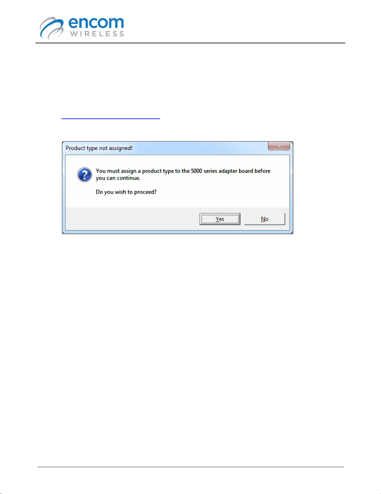
9. If a product code has not yet been assigned to the 5000 series adapter card, you will be
prompted to do so:
Refer to the Setting the 5000 Series Radio Product Code topic for instructions on setting the
product code.
10.After the radio's configuration settings have been retrieved, the radio is shown as being online.
Page 22
© 2012-2015 Encom Wireless Data Solutions Inc.For ENCOM PULSE Link Version 2.2.6
ENCOM PULSE Link
USER MANUAL
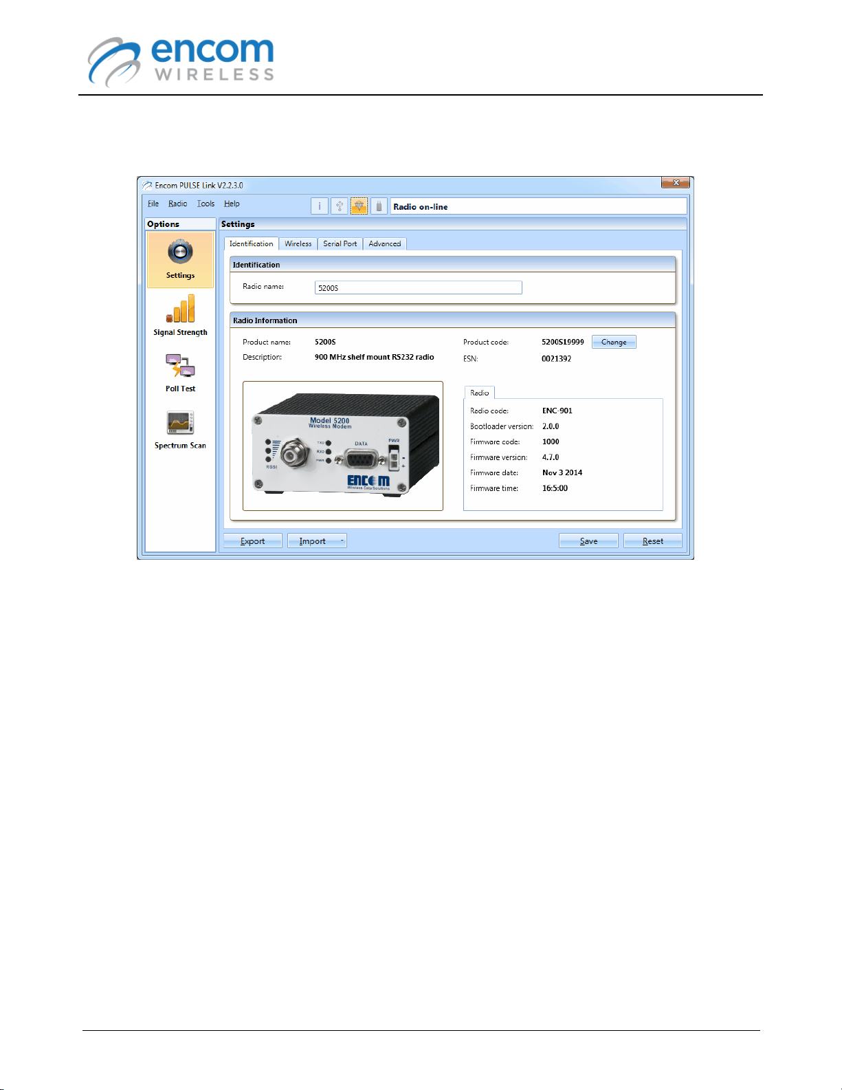
11.The radio configuration panel is displayed. At this point you can use ENCOM PULSE Link to
manage your radio.
Page 23
© 2012-2015 Encom Wireless Data Solutions Inc.For ENCOM PULSE Link Version 2.2.6
ENCOM PULSE Link
USER MANUAL
Setting the 5000 Series Radio Product Code
When you connect to a 5000 series radio in which a 5000 series adapter card has been installed,
you will be prompted to assign a product type to the adapter card. To following steps describe the
process of assigned the product type:
1. Run the ENCOM PULSE Link application on your computer.
2. Connect to the 5000 series radio using a serial or serial-to-USB cable.
3. After the radio is discovered, you will be prompted to assign a product type:
4. Click the Yes button to proceed.
Page 24
© 2012-2015 Encom Wireless Data Solutions Inc.For ENCOM PULSE Link Version 2.2.6
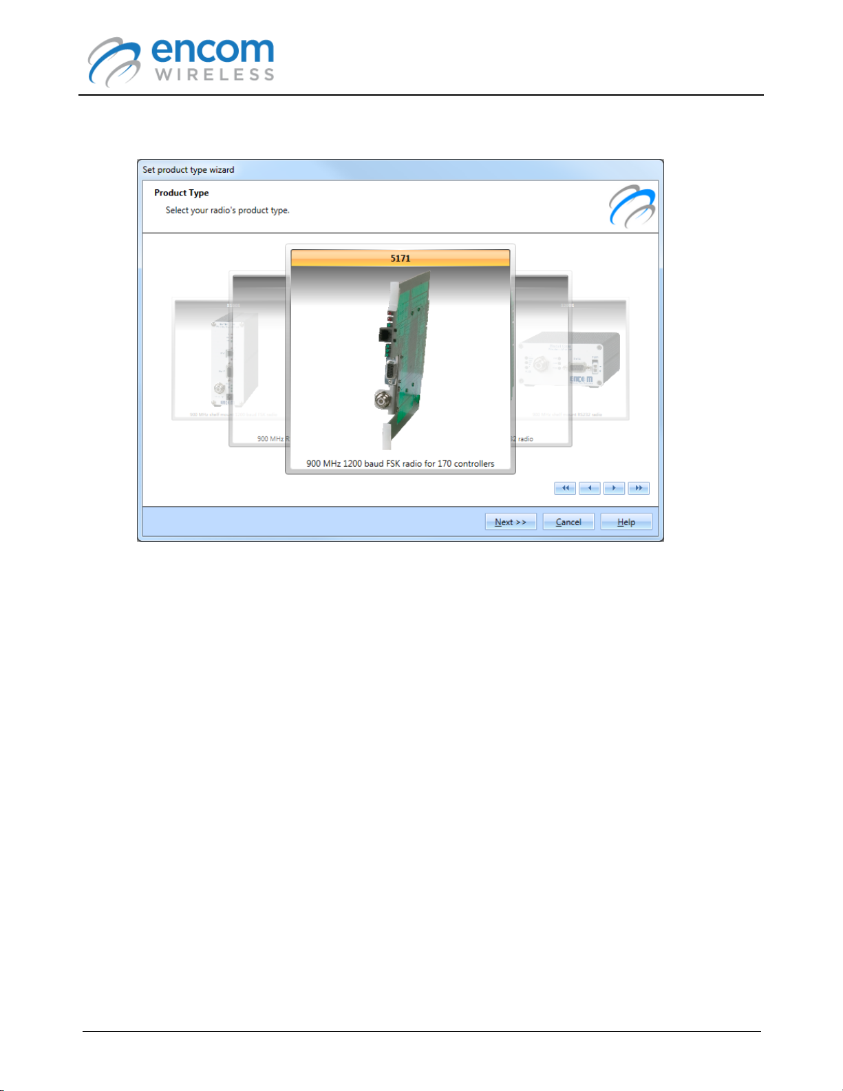
5. The Set product type wizard will be displayed:
ENCOM PULSE Link
USER MANUAL
6. Select the model associated with your 5000 series radio. The model name is normally found
on the front of the radio. Make sure that you choose the correct model, otherwise the radio
may not operate properly.
7. Press Next to continue.
Page 25
© 2012-2015 Encom Wireless Data Solutions Inc.For ENCOM PULSE Link Version 2.2.6
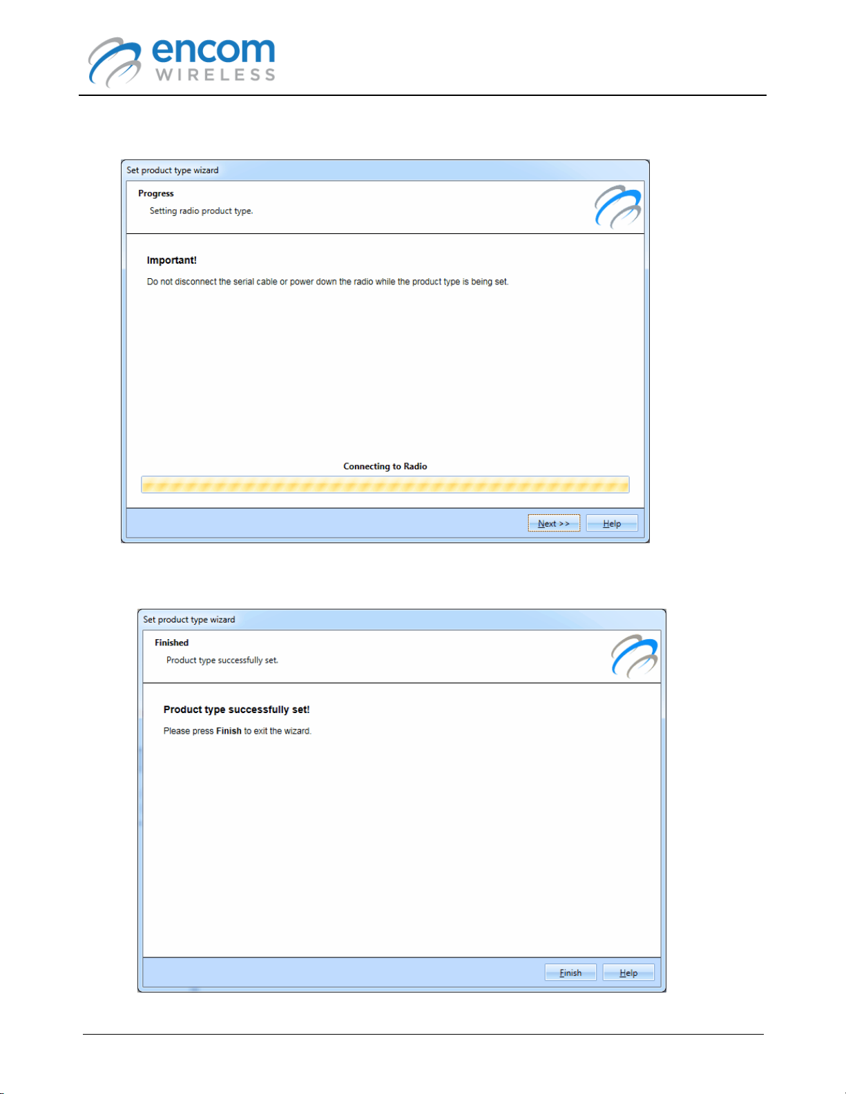
The wizard will display a progress bar while the radio is configured.
ENCOM PULSE Link
USER MANUAL
8. After the radio is configured, the wizard will display the following report:
Page 26
© 2012-2015 Encom Wireless Data Solutions Inc.For ENCOM PULSE Link Version 2.2.6
ENCOM PULSE Link
USER MANUAL
9. Click Finish to return to the main window.
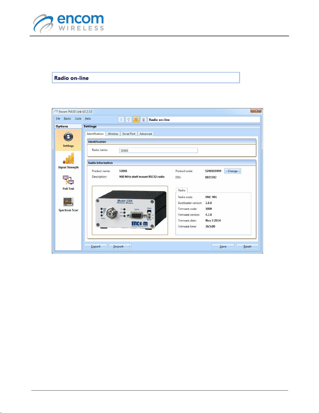
10.PULSE Link will retrieve the radio's new configuration, and show the radio as being on-line.
11.The radio configuration panel is displayed. At this point you can use ENCOM PULSE Link to
manage your radio.
Page 27
© 2012-2015 Encom Wireless Data Solutions Inc.For ENCOM PULSE Link Version 2.2.6
ENCOM PULSE Link
USER MANUAL
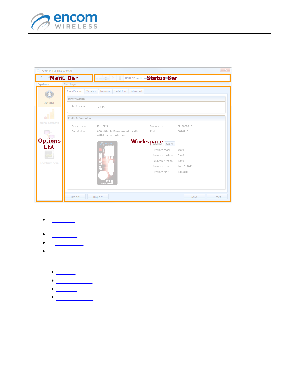
User Interface
The following screen shot shows the main window of a typical ENCOM PULSE Link session:
The main features of the PULSE Link user interface include:
A Menu Bar at the top of the window that allows you to access the application's less-frequently
used features.
A Status Bar that displays the current state of the application.
An Options List that allows you to choose the task you want to carry out.
A Workspace that contains the user interface associated with the currently selected option.
Depending on the type of radio connected to PULSE Link, one of more of the following options
are available:
Settings
Signal Strength
Poll Test
Spectrum Scan
Page 28
© 2012-2015 Encom Wireless Data Solutions Inc.For ENCOM PULSE Link Version 2.2.6

ENCOM PULSE Link
USER MANUAL
Menu Bar
The main menu bar provides access to the less-frequently used ENCOM PULSE Link functions.
The following options are available:
File Menu
Exit
Radio Menu
Upgrade
Recover
Restore to Factory Defaults
Tools Menu
Demo Mode
Help Menu
Topics
About
Page 29
© 2012-2015 Encom Wireless Data Solutions Inc.For ENCOM PULSE Link Version 2.2.6

File Menu Functions
Exit
Select Exit from the File menu to shut down ENCOM PULSE Link.
ENCOM PULSE Link
USER MANUAL
Page 30
© 2012-2015 Encom Wireless Data Solutions Inc.For ENCOM PULSE Link Version 2.2.6

ENCOM PULSE Link
USER MANUAL
Radio Menu Functions
Upgrade
Select Upgrade from the Radio menu to upgrade (or downgrade) the radio's firmware.
The upgrade processes for PULSE and iPULSE radios are significantly different. Refer to the
appropriate topic for the type of radio you are upgrading:
Upgrading a PULSE Radio
Upgrading an iPULSE Radio
Upgrading a 5000 Series Radio
Page 31
© 2012-2015 Encom Wireless Data Solutions Inc.For ENCOM PULSE Link Version 2.2.6

Upgrading a PULSE Radio
To upgrade a PULSE radio's firmware:
1. Make sure that the radio is powered, and then connect it to your computer via the USB cable.
2. Wait until PULSE Link has retrieved the radio's configuration settings.
3. Select Upgrade from the Radio menu. The Firmware upgrade wizard form is displayed:
ENCOM PULSE Link
USER MANUAL
Page 32
© 2012-2015 Encom Wireless Data Solutions Inc.For ENCOM PULSE Link Version 2.2.6

ENCOM PULSE Link
USER MANUAL
4. Check the I have read and understand the preceding warning option, and then click Next
to continue.
The wizard will display a list of all firmware available for upgrading or downgrading.
Page 33
© 2012-2015 Encom Wireless Data Solutions Inc.For ENCOM PULSE Link Version 2.2.6

ENCOM PULSE Link
USER MANUAL
5. Select the firmware version you want to upgrade or downgrade to. Unless instructed to do so,
you should always upgrade to the latest firmware version. Click Next to continue:
The wizard will display a progress bar while the radio is upgraded.
Page 34
© 2012-2015 Encom Wireless Data Solutions Inc.For ENCOM PULSE Link Version 2.2.6

ENCOM PULSE Link
USER MANUAL
6. When the upgrade process is complete, the wizard will display the following report:
7. Your radio is now upgraded and ready to use. Click Finish to return to the main window.
Page 35
© 2012-2015 Encom Wireless Data Solutions Inc.For ENCOM PULSE Link Version 2.2.6

Upgrading an iPULSE Radio
To upgrade an iPULSE radio's firmware:
1. Connect to the iPULSE radio as described in the Connecting to an iPULSE Radio topic.
2. Select Upgrade from the Radio menu. The Firmware upgrade wizard form is displayed:
ENCOM PULSE Link
USER MANUAL
Page 36
© 2012-2015 Encom Wireless Data Solutions Inc.For ENCOM PULSE Link Version 2.2.6

ENCOM PULSE Link
USER MANUAL
3. Check the I have read and understand the preceding warning option, and then click Next
to continue.
The wizard will display a list of all firmware available for upgrading. Note that downgrading is
not currently allowed for iPULSE radios.
Page 37
© 2012-2015 Encom Wireless Data Solutions Inc.For ENCOM PULSE Link Version 2.2.6

ENCOM PULSE Link
USER MANUAL
4. Select the firmware version you want to upgrade to. Unless instructed to do so, you should
always upgrade to the latest firmware version. Click Next to continue:
The wizard will display an activity bar while the radio is upgraded. Note that it can can take up
to 5 minutes to complete a firmware upgrade.
Page 38
© 2012-2015 Encom Wireless Data Solutions Inc.For ENCOM PULSE Link Version 2.2.6

ENCOM PULSE Link
USER MANUAL
5. When the upgrade process is complete, the wizard will display the following report:
6. Your radio is now upgraded and ready to use. Click Finish to return to the main window.
Page 39
© 2012-2015 Encom Wireless Data Solutions Inc.For ENCOM PULSE Link Version 2.2.6

ENCOM PULSE Link
Upgrading a 5000 Series Radio
To upgrade a 5000 series radio in which a 5000 series adapter card has been installed:
1. Make sure that the radio is powered, and then connect it to your computer via a serial or
serial-to-USB cable.
2. Click the Connect to serial device button at the left of the status bar.
3. The Connect to device serial port form is displayed.
USER MANUAL
4. Select the communications port to which the radio is connected, and then click the Connect
button.
5. Wait until PULSE Link has retrieved the radio's configuration settings.
Page 40
© 2012-2015 Encom Wireless Data Solutions Inc.For ENCOM PULSE Link Version 2.2.6

ENCOM PULSE Link
USER MANUAL
6. Select Upgrade from the Radio menu. The Firmware upgrade wizard form is displayed:
Page 41
© 2012-2015 Encom Wireless Data Solutions Inc.For ENCOM PULSE Link Version 2.2.6

ENCOM PULSE Link
USER MANUAL
7. Check the I have read and understand the preceding warning option, and then click Next
to continue.
The wizard will display a list of all firmware available for upgrading or downgrading.
Page 42
© 2012-2015 Encom Wireless Data Solutions Inc.For ENCOM PULSE Link Version 2.2.6

ENCOM PULSE Link
USER MANUAL
8. Select the firmware version you want to upgrade or downgrade to. Unless instructed to do so,
you should always upgrade to the latest firmware version. Click Next to continue:
The wizard will display a progress bar while the radio is upgraded.
Page 43
© 2012-2015 Encom Wireless Data Solutions Inc.For ENCOM PULSE Link Version 2.2.6

ENCOM PULSE Link
USER MANUAL
9. When the upgrade process is complete, the wizard will display the following report:
10.Your radio is now upgraded and ready to use. Click Finish to return to the main window.
Page 44
© 2012-2015 Encom Wireless Data Solutions Inc.For ENCOM PULSE Link Version 2.2.6

ENCOM PULSE Link
USER MANUAL
Recover
Select Recover from the Radio menu to restore a PULSE of 5000 series radio after a failed
firmware upgrade. Depending on the problem with the firmware, PULSE Link may not be able to
communicate with the radio. If this occurs, the application will cycle through all possible combination
of baud rates and serial settings in an attempt to communicate with it. Recovering the radio may fix
this issue if it occurs.
Note that it is not possible to recover an iPULSE radio if a firmware upgrade fails. If the radio no
longer works after a firmware upgrade, it will have to be sent back to ENCOM for repair.
Refer to the following topic for instructions on recovering a PULSE or 5000 series radio:
Recovering a PULSE Radio
Recovering a 5000 Series Radio
Page 45
© 2012-2015 Encom Wireless Data Solutions Inc.For ENCOM PULSE Link Version 2.2.6

Recovering a PULSE Radio
To recover a PULSE radio:
1. Make sure that the radio is powered, and then connect it to your computer via the USB cable.
2. Select Recover from the Radio menu. The Radio recovery wizard form is displayed:
ENCOM PULSE Link
USER MANUAL
3. Check the I have read and understand the preceding warning option, and then click Next
to continue.
Page 46
© 2012-2015 Encom Wireless Data Solutions Inc.For ENCOM PULSE Link Version 2.2.6

ENCOM PULSE Link
The wizard will display the type of products that are supported by PULSE Link.
USER MANUAL
4. Select the PULSE radio option, then then click Next to continue.
Page 47
© 2012-2015 Encom Wireless Data Solutions Inc.For ENCOM PULSE Link Version 2.2.6

ENCOM PULSE Link
The wizard will display the list of PULSE radios that are supported by PULSE Link.
USER MANUAL
When an upgrade fails, the radio loses its identity. In order to recover it, you must select the
appropriate model from the list. The model name is normally found on the front panel of the radio.
Make sure that you choose the correct model, otherwise the radio may not operate properly.
Page 48
© 2012-2015 Encom Wireless Data Solutions Inc.For ENCOM PULSE Link Version 2.2.6

5. Select the appropriate radio model, and press Next to continue.
The wizard will prompt you to disconnect all cables from the radio.
ENCOM PULSE Link
USER MANUAL
Page 49
© 2012-2015 Encom Wireless Data Solutions Inc.For ENCOM PULSE Link Version 2.2.6

ENCOM PULSE Link
USER MANUAL
6. After you have disconnected both cables, press Next.
A countdown timer will be displayed. The radio must be powered off for at least 60 seconds
before proceeding.
Page 50
© 2012-2015 Encom Wireless Data Solutions Inc.For ENCOM PULSE Link Version 2.2.6

ENCOM PULSE Link
7. When the timer expires, the wizard will prompt you to plug in the USB cable.
USER MANUAL
Page 51
© 2012-2015 Encom Wireless Data Solutions Inc.For ENCOM PULSE Link Version 2.2.6

ENCOM PULSE Link
USER MANUAL
8. Plug in the USB cable. A second countdown timer will be displayed. Again, wait until the timer
expires before proceeding.
Page 52
© 2012-2015 Encom Wireless Data Solutions Inc.For ENCOM PULSE Link Version 2.2.6

ENCOM PULSE Link
9. When the timer expires, the wizard will prompt you to plug in the power cable.
USER MANUAL
Page 53
© 2012-2015 Encom Wireless Data Solutions Inc.For ENCOM PULSE Link Version 2.2.6

ENCOM PULSE Link
10.Plug in the power cable. The recovery process will start automatically.
The wizard will display a progress bar while the radio is loaded with the firmware.
USER MANUAL
Page 54
© 2012-2015 Encom Wireless Data Solutions Inc.For ENCOM PULSE Link Version 2.2.6

ENCOM PULSE Link
If you recover a radio that contains an ECN-900 radio module, you will be asked to
repeat steps 5 to 10.
The latest available version of the radio firmware will be installed when a radio is
recovered.
USER MANUAL
11.When the recovery process is complete, the wizard will display the following report:
12.Your radio is now recovered and ready to use. Click Finish to return to the main window.
Page 55
© 2012-2015 Encom Wireless Data Solutions Inc.For ENCOM PULSE Link Version 2.2.6

ENCOM PULSE Link
Recovering a 5000 Series Radio
To recover a 5000 series radio in which a 5000 series adapter card has been installed:
1. Make sure that the radio is powered, and then connect it to your computer via a serial or
serial-to-USB cable.
2. Select Recover from the Radio menu. The Radio recovery wizard form is displayed:
USER MANUAL
Page 56
© 2012-2015 Encom Wireless Data Solutions Inc.For ENCOM PULSE Link Version 2.2.6

ENCOM PULSE Link
USER MANUAL
3. Check the I have read and understand the preceding warning option, and then click Next
to continue.
The wizard will display the type of products that are supported by PULSE Link.
4. Select the 5000 Series Adapter Board option, then then click Next to continue.
Page 57
© 2012-2015 Encom Wireless Data Solutions Inc.For ENCOM PULSE Link Version 2.2.6

ENCOM PULSE Link
USER MANUAL
The wizard will display the list of 5000 series radios that are supported by PULSE Link.
When an upgrade fails, the radio loses its identity. In order to recover it, you must select the
appropriate model from the list. The model name is normally found on the front panel of the radio.
Make sure that you choose the correct model, otherwise the radio may not operate properly.
Page 58
© 2012-2015 Encom Wireless Data Solutions Inc.For ENCOM PULSE Link Version 2.2.6

5. Select the appropriate radio model, and press Next to continue.
The wizard will display the list of serial ports available on your computer.
ENCOM PULSE Link
USER MANUAL
Page 59
© 2012-2015 Encom Wireless Data Solutions Inc.For ENCOM PULSE Link Version 2.2.6

ENCOM PULSE Link
USER MANUAL
6. Select the serial port to which the radio is connected, and press Next to continue.
The wizard will prompt you to unplug the power cable from the radio.
Page 60
© 2012-2015 Encom Wireless Data Solutions Inc.For ENCOM PULSE Link Version 2.2.6

7. After you have disconnected the power cable, press Next.
The wizard will prompt you to plug the power cable back in the radio.
ENCOM PULSE Link
USER MANUAL
Page 61
© 2012-2015 Encom Wireless Data Solutions Inc.For ENCOM PULSE Link Version 2.2.6

8. After you have plugged the power cable back in, press Next.
The radio should be detected, and the recovery process will start:
ENCOM PULSE Link
USER MANUAL
Page 62
© 2012-2015 Encom Wireless Data Solutions Inc.For ENCOM PULSE Link Version 2.2.6

ENCOM PULSE Link
The latest available version of the radio firmware will be installed when a radio is
recovered.
USER MANUAL
9. When the recovery process is complete, the wizard will display the following report:
10.Your radio is now recovered and ready to use. Click Finish to return to the main window.
Page 63
© 2012-2015 Encom Wireless Data Solutions Inc.For ENCOM PULSE Link Version 2.2.6

ENCOM PULSE Link
When restoring an iPULSE radio to factory defaults, the existing IP address,
network mask and default gateway settings will not be disturbed in order to prevent
loss of communication with the radio.
USER MANUAL
Restore to Factory Defaults
Select Restore to Factory Defaults from the Radio menu to restore the configuration of a radio to
its factory default state.
The status indicator will display a message while the radio's configuration settings are being reset.
Note that when the status bar is red, you should not disconnect the USB, serial or Ethernet cable
from the radio, nor should you remove power from the radio.
Page 64
© 2012-2015 Encom Wireless Data Solutions Inc.For ENCOM PULSE Link Version 2.2.6

ENCOM PULSE Link
USER MANUAL
Tools Menu Functions
Demo Mode
Demo mode allows you to use the ENCOM PULSE Link application without being connected to a
physical radio. It is useful for learning and evaluation purposes.
To activate demo mode:
1. Make sure that ENCOM PULSE Link is NOT connected a radio.
2. Select Demo Mode from the Tools menu. The Select device to demo form is displayed.
Page 65
© 2012-2015 Encom Wireless Data Solutions Inc.For ENCOM PULSE Link Version 2.2.6

ENCOM PULSE Link
USER MANUAL
3. Select the type of device you want to demo, and then click the Next button. The list of
available device models is displayed:
4. Select the radio model you want to demo, and press OK to continue.
ENCOM PULSE Link will simulate the operation of acquiring the settings from the radio.
Page 66
© 2012-2015 Encom Wireless Data Solutions Inc.For ENCOM PULSE Link Version 2.2.6

ENCOM PULSE Link
USER MANUAL
The settings for the selected radio model are then displayed in the application's main window:
5. At this point, you can carry out any function that can be used with a physical radio.
ENCOM PULSE Link will simulate the operations you carry out to mimic physical radios as
closely as possible (including the amount of time it takes to perform the various tasks).
6. To exit demo mode, select Demo Mode from the Tools menu again.
Page 67
© 2012-2015 Encom Wireless Data Solutions Inc.For ENCOM PULSE Link Version 2.2.6

ENCOM PULSE Link
USER MANUAL
Help Menu Functions
Topics
Select Topics from the Help menu to display the ENCOM PULSE Link on-line help.
About
Select About from the Help menu to display information about the ENCOM PULSE Link application.
Page 68
© 2012-2015 Encom Wireless Data Solutions Inc.For ENCOM PULSE Link Version 2.2.6

ENCOM PULSE Link
Item
Description
Search for iPULSE devices button.
Display a form that allows you to search for
and select an iPULSE device.
See the Search for iPULSE Devices Button
topic for more information.
Detect USB devices button.
Resumes the detection of USB-based PULSE
devices.
See Detect USB Devices Button topic for
more information.
Connect to serial device button.
Allows you to connect to a serial port based
device, such as a 5000 series radio in which
a 5000 series adapter board has been
installed.
See the Connect to serial device button topic
for more information.
USB serial port settings button.
Allows you to set the serial port settings that
ENCOM PULSE Link will use to communicate
with a PULSE radio.
See the USB Serial Port Settings Button topic
for more information.
USER MANUAL
Status Bar
The status bar provides feedback on the current state of the PULSE Link application. It also
contains a number of buttons that allow you to search for radios, and specify the communication
parameters to use when communicating with a serial radio.
The following table briefly describes the items found in the status bar.
Page 69
© 2012-2015 Encom Wireless Data Solutions Inc.For ENCOM PULSE Link Version 2.2.6

ENCOM PULSE Link
Status information panel.
Provides feedback on the current state of the
ENCOM PULSE Link application
See the Status Information Panel topic for
more information.
USER MANUAL
Page 70
© 2012-2015 Encom Wireless Data Solutions Inc.For ENCOM PULSE Link Version 2.2.6

ENCOM PULSE Link
USER MANUAL
Search for iPULSE Radios Button
Click the Search for iPULSE devices button, , at the left of the status information panel to
display the iPULSE Radios form:
The iPULSE Radios form displays the iPULSE radios that are active on your local network. To load
the configuration associated a specific radio, perform one of the following:
Click the left mouse button on a radio that is available, and then click the Select button.
Double-click the left mouse button on a radio that is available.
Refer to the Connecting to an iPULSE Radio topic for detailed information on the iPULSE Radios
form.
Page 71
© 2012-2015 Encom Wireless Data Solutions Inc.For ENCOM PULSE Link Version 2.2.6

ENCOM PULSE Link
USER MANUAL
Detect USB Devices Button
Click the Detect USB devices button, , at the left of the status information panel to re-enable
the process that detects USB-based PULSE radios.
When an iPULSE radio configuration is loaded into the PULSE Link application, the process that
detects USB-based PULSE radios is disabled.
When you are done working with iPULSE radios, and wish to connect to a USB-based PULSE
radio, simply click on the Detect USB devices button.
Page 72
© 2012-2015 Encom Wireless Data Solutions Inc.For ENCOM PULSE Link Version 2.2.6

ENCOM PULSE Link
USER MANUAL
Connect to serial device button
Click the Connect to serial device button, , at the left of the status information panel to
connect to a serial port based radio.
When you click on the Connect to serial device button, the Connect to device serial port form is
displayed.
Select the serial communications port to which the radio is connected, and then click the Connect
button.
ENCOM PULSE Link will then connect to the radio and load its configuration.
Refer to the Connecting to a 5000 Series Radio topic for detailed information on connecting to a
serial radio.
Page 73
© 2012-2015 Encom Wireless Data Solutions Inc.For ENCOM PULSE Link Version 2.2.6

ENCOM PULSE Link
If ENCOM PULSE Link can't communicate with the radio using the settings you
specify, it will keep trying to communicate using all possible combinations of
communication settings.
USER MANUAL
USB Serial Port Settings Button
Click the USB Serial Port Settings button, , at the left of the status information panel to
configure the serial port that ENCOM PULSE Link will use to communicate with a PULSE radio.
To change the serial communication settings:
1. While ENCOM PULSE Link is not currently connected to a PULSE radio, click the USB
Serial Port Settings button. (You can also do this while PULSE Link is searching for the
communication settings of a PULSE radio that is plugged into the USB port). The USB Serial
Port Settings form is displayed.
2. Change the settings to match your radio's currently configured serial port settings, and then
click OK.
3. ENCOM PULSE Link will attempt to use the specified settings to communicate with the radio.
Page 74
© 2012-2015 Encom Wireless Data Solutions Inc.For ENCOM PULSE Link Version 2.2.6

ENCOM PULSE Link
Message
Description
Attempting to communicate at 1200
baud, 8N1
Displayed when the application is attempting to
communicate with the radio.
Connect to radio using USB or
Ethernet cable
Displayed if there is no radio connected to your computer.
Use a USB cable connect to a PULSE radio, and an
Ethernet cable to connect to an iPULSE radio.
Could not communicate with radio
ENCOM PULSE Link was able to detect the radio, but was
not able to communicate with it.
This error normally indicates that another application is
using the USB serial port used to communicate with a
PULSE radio.
It may also indicate a hardware problem with the radio, or a
radio that was not designed to be used with ENCOM PULSE
Link.
Could not get radio settings, please
try again
An error occurred trying to get the radio settings.
For PULSE radios, unplug the USB and power cables from
USER MANUAL
Status Information Panel
The status information panel provides feedback on the current state of the ENCOM PULSE Link
application.
The spinner at the right of the status panel, , indicates that the application is currently interacting
with a radio.
Under normal operation, the background of the status bar is white. When the application is
communicating with the radio, the background turns red.
When the background is red, you will not be able to shut down ENCOM PULSE Link. You should
refrain from powering off the radio or disconnecting the USB cable while the application is in this
state. Doing so when connected to a PULSE radio could prevent the radio from being able to
communicate properly over the serial port (or the FSK port for FSK radios). If this happens, you may
have to use PULSE Link to restore the radio's configuration.
The following table describes the messages that can be displayed in the status panel:
Page 75
© 2012-2015 Encom Wireless Data Solutions Inc.For ENCOM PULSE Link Version 2.2.6

ENCOM PULSE Link
the radio, wait a minute, and plug them back in. The radio
should be detected, and its configuration automatically
loaded.
For iPULSE radios, unplug the Ethernet and power cables
from the radio, wait a minute, plug them back in, click the
Search for iPULSE devices button, select the radio in the
iPulse Radios form, and click the Load button to load the
radio's configuration.
Contact your ENCOM customer service representative if the
problem persists.
Could not update radio settings,
please try again
An error occurred trying to update the radio settings.
For PULSE radios, unplug the USB and power cables from
the radio, wait a minute, plug them back in, wait for the
radio's configuration to be loaded, and then try again.
For iPULSE radios, unplug the Ethernet and power cables
from the radio, wait a minute, plug them back in, click the
Search for iPULSE devices button, select the radio in the
iPulse Radios form, click the Load button to load the radio's
configuration, and then try again.
Contact your ENCOM customer service representative if the
problem persists.
Demo mode
The application is currently running in demo mode.
Getting radio settings, please wait
Displayed while the application is getting the settings from
the radio. Do not disconnect the radio while the application
is in this state.
Incompatible radio found
ENCOM PULSE Link was able to communicate with the
radio, but determined that it is not able to support it.
You may need to upgrade to the latest version of ENCOM
PULSE Link, or use a different application that was designed
to support the radio.
iPULSE radio on-line (192.168.0.1)
The application is connected to an iPULSE radio that has
the specified IP address.
Multiple radios found, please unplug
all but one
ENCOM PULSE Link can only manage one USB-based
PULSE radio at a time. Unplug all other PULSE radios in
order to proceed.
Radio detected, attempting to
communicate
ENCOM PULSE Link has detected a radio on the USB port,
and is currently trying to communicate with it.
USER MANUAL
Page 76
© 2012-2015 Encom Wireless Data Solutions Inc.For ENCOM PULSE Link Version 2.2.6

ENCOM PULSE Link
Radio on-line
The application is connected to a PULSE radio, but is not
currently interacting with it.
Recovering radio
The Radio recovery wizard is currently active. See the
Radio -> Recover topic for more information.
Restoring radio to factory defaults,
please wait
Displayed while the radio's configuration is being restored to
factory defaults. Do not disconnect the radio while the
application is in this state.
Searching for iPULSE radios
The iPULSE Radios form is currently active, and ENCOM
PULSE Link is searching for iPULSE radios on the local
network.
Updating radio settings, please wait
Displayed while the application is updating the radio
settings. Do not disconnect the radio while the application is
in this state.
Upgrading radio
The Firmware upgrade wizard is currently active. See the
Radio -> Upgrade topic for more information.
USER MANUAL
Page 77
© 2012-2015 Encom Wireless Data Solutions Inc.For ENCOM PULSE Link Version 2.2.6

ENCOM PULSE Link
USER MANUAL
Options List
The options list allows you to access the various functions of ENCOM PULSE Link. Click on the
desired option to display the associated user interface in the PULSE Link workspace area.
Refer to the following topics for information on each of the options:
Settings Panel
Signal Strength Panel
Poll Test Panel
Spectrum Scan Panel
Page 78
© 2012-2015 Encom Wireless Data Solutions Inc.For ENCOM PULSE Link Version 2.2.6

ENCOM PULSE Link
USER MANUAL
Settings Panel
The Settings panel shows the configuration settings of the serial radio that is currently connected
to your computer.
The configuration settings are logically grouped using a tabbed interface. The following topics
describe the settings found in each tab:
Identification Tab
Wireless Tab
Network Tab
Serial Port Tab
Advanced Tab
Page 79
© 2012-2015 Encom Wireless Data Solutions Inc.For ENCOM PULSE Link Version 2.2.6

ENCOM PULSE Link
Identification
Field Name
Description
Radio name
Enter a name used to identify the radio (up to a maximum of 15
characters for PULSE radios, and 50 characters for iPULSE radios).
New firmware
available
Indicates that new radio firmware is available. Click on this link to display
the Firmware upgrade wizard.
This indicator is not displayed if the radio's firmware is up to date.
Note that the indicator makes use of the firmware upgrade files that are
packaged with the ENCOM PULSE Link setup program. In order to
ensure that you have the latest firmware available, you should always
have the latest version of ENCOM PULSE Link installed.
USER MANUAL
Identification Tab
The Identification tab displays information on the radio that is connected to your computer. It also
allows you to assign a friendly name to the radio.
The following screen shot shows the contents of the Identification tab for a typical serial radio.
The following tables describe the settings found in each group in the Identification tab.
Page 80
© 2012-2015 Encom Wireless Data Solutions Inc.For ENCOM PULSE Link Version 2.2.6

ENCOM PULSE Link
Radio Information
Field Name
Description
Product name
The serial radio's model name.
Description
A short description of the radio's features.
Radio picture
A picture of the radio.
If the picture does not match the radio that is connected to your computer,
the radio may not have been properly provisioned.
In this case, you can use the Radio -> Recover function to correct the
discrepancy.
Product code
Internal code used to identify the serial radio model.
ESN
The electronic serial number that uniquely identifies the radio module.
Ethernet tab
Displays information associated with the radio's Ethernet interface (for
iPULSE radios only):
Field Name
Description
Firmware code
Internal code used to identify the Ethernet
interface firmware.
Firmware version
Version of the Ethernet interface
firmware.
Hardware version
Version of the Ethernet interface
hardware.
Firmware date
The date at which the Ethernet interface
firmware was released.
Firmware time
The time at which the Ethernet interface
firmware was released.
Radio tab
Displays information associated with the radio's 900 MHz radio module:
USER MANUAL
Page 81
© 2012-2015 Encom Wireless Data Solutions Inc.For ENCOM PULSE Link Version 2.2.6

ENCOM PULSE Link
Field Name
Description
Radio code
Identifies the type of wireless module
embedded in the radio.
Bootloader version
Version of the radio's bootloader
firmware.
Firmware code
Internal code used to identify the radio
firmware.
Firmware version
Version of the radio's application
firmware.
Firmware date
The date at which the radio's application
firmware was released.
Firmware time
The time at which the radio's application
firmware was released.
USER MANUAL
Page 82
© 2012-2015 Encom Wireless Data Solutions Inc.For ENCOM PULSE Link Version 2.2.6

ENCOM PULSE Link
Radio Mode
Field Name
Description
Operating mode
Specify the role of the radio in the network.
Role
Description
Master
The master radio normally has a direct, wired
connection to a controller.
The master broadcasts data to the repeater
and remote radios that make up the rest of
the network.
It also collects the data transmitted by the
USER MANUAL
Wireless Tab
The Wireless tab allows you to modify the radio's wireless settings.
The following screen shot shows the contents of the Wireless tab for a typical serial radio.
The following tables describe the settings found in each group in the Wireless tab.
Page 83
© 2012-2015 Encom Wireless Data Solutions Inc.For ENCOM PULSE Link Version 2.2.6

ENCOM PULSE Link
remote and repeater radios, and forwards it to
the network operations center.
In any given network, there is only one
master.
Repeater
A repeater is used to extend the range of the
master radio. Several repeaters can be
chained together to span long distances.
The repeater can also be connected to a
controller via its serial or FSK port.
Remote
A remote is normally connected to a controller
via its serial or FSK port.
The remote communicates directly with the
master, or with the closest repeater.
Repeater in system
Set to Yes if one or more repeaters are present in your 900 MHz radio
network.
Note that this setting is only applicable to the master radio. It is not
displayed for the Repeater and Remote radios.
Primary hop pattern
ENCOM serial radios employ a frequency-hopping method of transmitting
data. The radio's carrier frequency changes periodically according to one
of 64 pseudo-random sequences.
In order for two radios to communicate with each other, they must be
assigned the same hop pattern.
In a network with no repeaters, all radios must be assigned the same
primary hop pattern.
In a network with repeaters, the master and the radios that communicate
directly with it must be assigned the same primary hop pattern.
The radios that communicate directly with a repeater are assigned a
primary hop pattern that matches the repeater's repeater hop pattern.
Refer to the PULSE Link Network Example topic for more information on
assigning primary hop patterns.
Repeater hop pattern
This option is only available on repeater radios. It defines the hop pattern
to use between a repeater and the radios that communicate directly with
it.
The repeater's repeater hop pattern must be different than its primary hop
pattern in order to prevent interference between the master-facing and
remote-facing sides of the connection.
USER MANUAL
Page 84
© 2012-2015 Encom Wireless Data Solutions Inc.For ENCOM PULSE Link Version 2.2.6

ENCOM PULSE Link
Refer to the PULSE Link Network Example topic for more information on
assigning secondary hop patterns.
Network Settings
Field Name
Description
Network address
In order for the radios in a network to communicate with each other, they
must be assigned the same network address.
If another ENCOM 900 MHz radio network was located next to an existing
network, and both networks were using the same network address, there
would be an opportunity for the two networks to interfere with each other.
To prevent this, each of these networks should be assigned different
network addresses.
Unit address
The unit address is used to identify the radios in the network. Each radio
in the network should be assigned a different number.
By convention, the master is assigned a network address of 0. The
remaining repeaters and remotes are assigned addresses between 1 and
254.
Radio Settings
Field Name
Description
Output power
Select the power at which the radio will transmit.
ENCOM 900 MHz serial radios have very sensitive receivers that can
operate at very low signal levels. It is recommended that the lowest power
output necessary for a reliable connection be used. This will help with
power consumption, and will prevent unnecessary interference with other
devices operating within the same frequency band.
To determine the optimum power output, you should use the Signal
Strength tool provided by ENCOM PULSE Link. Start with the highest
power level, and decrease it until the signal strengths shown are between
-40 and -90 dBm for both radios.
RF noise filter
The RF noise filter is used to improve radio performance when operating
in a noisy RF environment.
When enabled, the RF noise filter will introduce about 6 dB of loss in the
received signal strength. Because of this, the effective range of the radio
will be shortened.
USER MANUAL
Page 85
© 2012-2015 Encom Wireless Data Solutions Inc.For ENCOM PULSE Link Version 2.2.6

ENCOM PULSE Link
Security Settings
Field Name
Description
Security key
The security key is used to encrypt the communication between the
radios, rendering the network more secure.
In order for the radios in a network to communicate with each other, they
must be assigned the same security key.
A value between 0 and 2147483647 can be chosen.
For greater security, you should use a large number with randomly
assigned digits.
AES encryption
If enabled, industry standard 128-bit AES encryption is applied to the
communication between the radios. This provides the best network
security possible for PULSE devices, although there may be a decrease
in network performance.
This option is only available if the radio contains an ENC-901 (or newer)
radio module.
AES key
The sequence of characters used to encrypt the communication between
the radios.
For greatest security, enter a random collection of alphabetical, numeric
and punctuation characters.
This option is only available if the radio contains an ENC-901 (or newer)
radio module.
USER MANUAL
Page 86
© 2012-2015 Encom Wireless Data Solutions Inc.For ENCOM PULSE Link Version 2.2.6

ENCOM PULSE Link
Network Settings
Field Name
Description
Obtain an IP address
automatically (DHCP)
Select this option if a DHCP server is available on your radio network, and
you want the DHCP server to assign an IP address to the radio.
Using the DHCP option is not recommended for radios installed in the
field. The IP address assigned to the radio could change, or the DHCP
server could fail and become unavailable. Both of these issues could
cause loss of connectivity with the radio.
Specify a static IP
address
(recommended)
Select this option to manually assign the radio's IP address.
ENCOM recommends this option because it provides for a more stable
network.
Note: It is important that each radio in the network is assigned a different
USER MANUAL
Network Tab
The Network tab allows you to modify the settings associated with the radio's Ethernet port. This tab
is only displayed for iPULSE radios.
The following screen shot shows the contents of the Network tab for a typical iPULSE radio.
The following tables describe the settings found in each group in the Network tab.
Page 87
© 2012-2015 Encom Wireless Data Solutions Inc.For ENCOM PULSE Link Version 2.2.6

ENCOM PULSE Link
IP address. Network performance can suffer greatly if two or more radios
are assigned the same IP address.
IP address
Enter the IP address of the radio. This is an Internet Protocol version 4
(IPv4) address, specified in dotted notation, as shown in the following
example:
Network mask
Enter the network mask. This is an Internet Protocol version 4 (IPv4)
address, specified in dotted notation, as shown in the following example:
Gateway address
Enter the IP address of the radio or router that allows the radio to connect
with devices that are outside of their local LAN or VLAN. This is an Internet
Protocol version 4 (IPv4) address, specified in dotted notation, as shown
in the following example:
Note that the default gateway's IP address must be in the same subnet as
the radio's IP address.
Serial Port Mode
Field Name
Description
Serial Mode
This option sets the protocol used by the iPULSE radio to communicate
with other devices (computer, iPULSE radio, TS1 terminal server, etc.)
via the Ethernet port. One of the following options can be selected:
Option
Description
P-MP Master
Mode
Allows the iPULSE radio to communicate
with an unlimited number of iPULSE radios
configured in P-MP Remote mode. The UDP
protocol is used for low latency serial data
transfer. This mode is extremely useful for
typical "polling" type protocols.
See the P-MP Master Mode topic for more
information.
USER MANUAL
Page 88
© 2012-2015 Encom Wireless Data Solutions Inc.For ENCOM PULSE Link Version 2.2.6

ENCOM PULSE Link
P-MP Remote
Mode
Works with conjunction with an iPULSE radio
configured in P-MP Master mode to provide
low latency serial data transfer using the
UDP protocol.
See the P-MP Remote Mode topic for more
information.
TCP Server
Mode
The radio waits for and accepts a connection
from a device or computer application
configured as a TCP client.
Up to four TCP clients can connect to a
single TCP server.
See the TCP Server Mode topic for more
information.
TCP Client
Mode
The radio initiates and maintains a
connection to a radio configured as a TCP
server.
The connection acts as a virtual wire
between two iPULSE networks.
See the TCP Client Mode topic for more
information.
TCP Client &
Server Mode
The radio can initiate a connection to, or
accept a connection request from, another
radio or computer that is configured in TCP
Client or TCP Server mode.
See the TCP Client & Server Mode topic for
more information.
VCOM UDP
Mode
This mode is used in conjunction with a UDP
based virtual COM port driver running on a
computer.
The iPULSE radio is connected to the
computer using its Ethernet interface, but
appears as a local, physical COM port to an
application running on the computer.
See the VCOM UDP Mode topic for more
information.
USER MANUAL
Page 89
© 2012-2015 Encom Wireless Data Solutions Inc.For ENCOM PULSE Link Version 2.2.6

ENCOM PULSE Link
The other fields that are displayed depend on the serial mode option that
is selected. Refer to the appropriate topics for information on the
configuration parameters associated with each option.
Login Credentials
Field Name
Description
User name
The user name used to login to the radio.
The default user name is admin.
Password
The password used to login to the radio.
The default password is admin.
Confirm password
The password used to login to the radio. This must match the value
entered in the Password field in order for the setting to be saved.
USER MANUAL
Page 90
© 2012-2015 Encom Wireless Data Solutions Inc.For ENCOM PULSE Link Version 2.2.6

ENCOM PULSE Link
USER MANUAL
P-MP Master Mode
The P-MP (point-to-multipoint) mode is used to bridge an unlimited number of PULSE radio
networks together. This allows serial devices from different PULSE networks to talk to each other
via an Ethernet network. Data is transferred using low-latency UDP packets, making the solution
ideal for polling applications.
The following diagram shows a typical context in which an iPULSE radio configured as a P-MP
Master is used.
In this scenario, serial data from the application running on the computer is sent to an existing
PULSE radio (PULSE radio 1), that relays the data to iPULSE radio 1. iPULSE radio 1, configured
as a P-MP Master, encapsulates this data in UDP packets that are broadcast to the iPULSE radios
configured as P-MP Remotes (iPULSE radio 2 and iPULSE radio 3). The P-MP remotes in turn
relay the data to the PULSE radios in their respective networks.
Page 91
© 2012-2015 Encom Wireless Data Solutions Inc.For ENCOM PULSE Link Version 2.2.6

ENCOM PULSE Link
Field Name
Description
Multicast IP address
Enter a multicast address to which UDP packets will be sent. This is an
Internet Protocol version 4 (IPv4) address, specified in dotted notation, as
shown in the following example:
Set the Multicast IP address setting of the P-MP remote radios to this
value.
Valid multicast addresses are in the range of 224.0.0.0 to
239.255.255.255.
The default address is 224.1.1.3.
Multicast port
Enter the port to which the multicast UDP packets will be sent.
Set the Multicast port setting of the P-MP remote radios to this value.
The default multicast port is 20001.
Listening port
Enter the port on which to listen for UDP packets coming from the remote
radios.
Set the Remote port setting of the P-MP remote radios to this value.
The default listening port is 20011.
The following table describes the settings associated with the P-MP Master mode.
USER MANUAL
Page 92
© 2012-2015 Encom Wireless Data Solutions Inc.For ENCOM PULSE Link Version 2.2.6

ENCOM PULSE Link
USER MANUAL
P-MP Remote Mode
The P-MP (point-to-multipoint) mode is used to bridge an unlimited number of PULSE radio
networks together. This allows serial devices from different PULSE networks to talk to each other
via an Ethernet network. Data is transferred using low-latency UDP packets, making the solution
ideal for polling applications.
The following diagram shows a typical context in which iPULSE radios configured as a P-MP
Remotes are used.
In this scenario, data coming from the serial devices in PULSE radio networks 2 and 3 are sent to
iPULSE radio 2 and 3 respectively. iPULSE radio 2 and 3 are configured to relay this data,
encapsulated in UDP packets, to iPULSE radio 1, that is configured as the P-MP Master. iPULSE
radio 1 in turn relays the serial data to PULSE radio network 1, where it eventually reaches the
application running on the computer.
Page 93
© 2012-2015 Encom Wireless Data Solutions Inc.For ENCOM PULSE Link Version 2.2.6

ENCOM PULSE Link
Field Name
Description
Remote IP address
Enter the IP address of the P-MP Master radio to which the P-MP Remote
reports. The P-MP Remote radio will automatically send data received
from its associated PULSE radio network to the P-MP Master.
The is an Internet Protocol version 4 (IPv4) address, specified in dotted
notation, as shown in the following example:
Remote port
Enter the UDP port to which data received from the P-MP Remote radio's
associated PULSE radio network will be sent.
Set this value to the Listening port setting of the P-MP Master radio.
The default listening port is 20011.
Multicast IP address
Enter the multicast address that the P-MP Remote radio listens to. This is
an Internet Protocol version 4 (IPv4) address, specified in dotted notation,
as shown in the following example:
Set this value to the Multicast IP address setting of the P-MP Master
radio.
Valid multicast addresses are in the range of 224.0.0.0 to
239.255.255.255.
The default address is 224.1.1.3.
Multicast port
Enter the UDP port on which the P-MP Remote listens for multicast
packets.
Set this value to the Multicast port setting of the P-MP Master radio.
The default multicast port is 20001.
The following table describes the settings associated with the P-MP Remote mode.
USER MANUAL
Page 94
© 2012-2015 Encom Wireless Data Solutions Inc.For ENCOM PULSE Link Version 2.2.6

ENCOM PULSE Link
USER MANUAL
TCP Server Mode
The TCP Server mode is used to provide error-free communications between TCP clients, such as
an application running on a computer, and serial devices found in a PULSE radio network. The TCP
clients are connected to the iPULSE radios using a direct Ethernet connection. Up to four
concurrent client connections are supported by each iPULSE radio.
The following diagram shows a typical context in which an iPULSE radio configured as a TCP
Server is used.
In this scenario, an application running on a computer needs access to the serial devices in PULSE
radio networks 1 and 2. The computer is connected to the iPULSE radios via their Ethernet ports.
iPULSE radio 1 provides access to PULSE radio network 1, and iPULSE radio 2 provides access to
PULSE radio network 2. The iPULSE radios are always listening for connection requests from a
TCP client. The application running on the computer initiates separate TCP connections to the
iPULSE radios as required. When a TCP connection is established, data can be sent to, and
received from, the serial devices in the PULSE radio networks.
Note that in this scenario, it is not possible for a serial device in PULSE radio network 1 to
communicate with a serial device in PULSE radio network 2 (and vice-versa).
The following table describes the settings associated with the TCP Server mode.
Page 95
© 2012-2015 Encom Wireless Data Solutions Inc.For ENCOM PULSE Link Version 2.2.6

ENCOM PULSE Link
Field Name
Description
Listening port
Enter the TCP port on which the radio will listen for incoming connection
requests.
The default listening port is 20011.
In-connection timeout
Enter the maximum amount of time, in seconds, to keep a connection
active while it is idle (no data is being transferred). If this timeout is
exceeded, the connection is dropped.
The default in-connection timeout is 300 seconds.
USER MANUAL
Page 96
© 2012-2015 Encom Wireless Data Solutions Inc.For ENCOM PULSE Link Version 2.2.6

ENCOM PULSE Link
USER MANUAL
TCP Client Mode
The TCP client/server mode is used to bridge two or more PULSE radio networks together. This
allows serial devices from different PULSE networks to talk to each other via an Ethernet network.
The following diagram shows a typical context in which iPULSE radios configured as TCP Clients
are used.
In this scenario, the radios configured as TCP client radios (iPULSE radio 2 and iPULSE radio 3)
establish a connection to the radio configured as a TCP Server (iPULSE radio 1) when data is
received from their respective PULSE radio networks. When the connection is established, any data
received from the client PULSE radio networks is passed on to the TCP Server, that forwards the
data to PULSE radio network 1.
Note that in this scenario, it is not possible for a serial device in PULSE radio network 2 to
communicate with a serial device in PULSE radio network 3 (and vice-versa).
Page 97
© 2012-2015 Encom Wireless Data Solutions Inc.For ENCOM PULSE Link Version 2.2.6

ENCOM PULSE Link
Field Name
Description
Remote server IP
Enter the IP address of the TCP Server to which data received from the
client PULSE radio network will be sent.
This is an Internet Protocol version 4 (IPv4) address, specified in dotted
notation, as shown in the following example:
Remote server port
Enter the TCP port to which the data received from the client PULSE
radio network will be sent.
Set this value to the Listening port setting of the TCP Server radio.
The default server port is 20011.
Out-connection
timeout
Enter the maximum amount of time, in seconds, to keep the connection
active while it is idle (no data is being transferred). If this timeout is
exceeded, the connection is dropped.
The default in-connection timeout is 60 seconds.
The following table describes the settings associated with the TCP Client mode.
USER MANUAL
Page 98
© 2012-2015 Encom Wireless Data Solutions Inc.For ENCOM PULSE Link Version 2.2.6

ENCOM PULSE Link
USER MANUAL
TCP Client & Server Mode
The TCP client/server mode is used to bridge two PULSE radio networks together. This allows
serial devices from different PULSE networks to talk to each other via an Ethernet network. A semipersistent TCP connection is established between two client/server radios that provides an efficient
mechanism for transferring large quantities of data.
The following diagram shows a typical context in which two iPULSE radios configured in TCP
Client/Server mode are used.
In this scenario, either of the TCP Client/Server radios can establish a connection to the other radio
when data is received from their respective PULSE radio networks. When a connection is
established, any data received by either of the iPULSE radios is passed on to the other radio. A
serial device from either PULSE network can communicate with a serial device from the other
PULSE network. As well, applications running on a computer that is connected to the Ethernet
network can access all of the serial devices in the two PULSE networks.
Page 99
© 2012-2015 Encom Wireless Data Solutions Inc.For ENCOM PULSE Link Version 2.2.6

ENCOM PULSE Link
Field Name
Description
Remote server IP
Enter the IP address of the other TCP Client/Server radio.
The is an Internet Protocol version 4 (IPv4) address, specified in dotted
notation, as shown in the following example:
Remote server port
Enter the TCP port to which the data received from the associated
PULSE radio network will be sent.
Set this value to the Listening port setting of the other TCP Client/Server
radio.
The default server port is 20011.
Out-connection
timeout
Enter the maximum amount of time, in seconds, to keep the connection
initiated by this radio active while it is idle (no data is being transferred). If
this timeout is exceeded, the connection is dropped.
The default in-connection timeout is 60 seconds.
Listening port
Enter the TCP port on which the radio will listen for incoming connection
requests from the other radio.
The default listening port is 20011.
In-connection timeout
Enter the maximum amount of time, in seconds, to keep the connection
initiated by the other radio active while it is idle (no data is being
transferred). If this timeout is exceeded, the connection is dropped.
The default in-connection timeout is 300 seconds.
USER MANUAL
The following table describes the settings associated with the TCP Client/Server mode.
Page 100
© 2012-2015 Encom Wireless Data Solutions Inc.For ENCOM PULSE Link Version 2.2.6
 Loading...