

TECHNICAL BULLETIN
Port 1 (In)
Assignments
RNB
Female
Connector
(Port1) IN
M12x1,
4-pin,
D-coded
Tx+ 1
Rx+ 2
Tx- 3
Rx- 4
Power
Assignments
RNB
Connector
(Power)
M12x1,
4-pin,
A-coded
(+) Vcc 1
n. c. 2
GND 3
n. c. 4
Port 2 (Out)
Assignments
RNB
Female
Connector
(Port2) OUT
M12x1,
4-pin,
D-coded
Tx+ 1
Rx+ 2
Tx- 3
Rx- 4
TB-542: Model A58E Series Quick Installation Guide
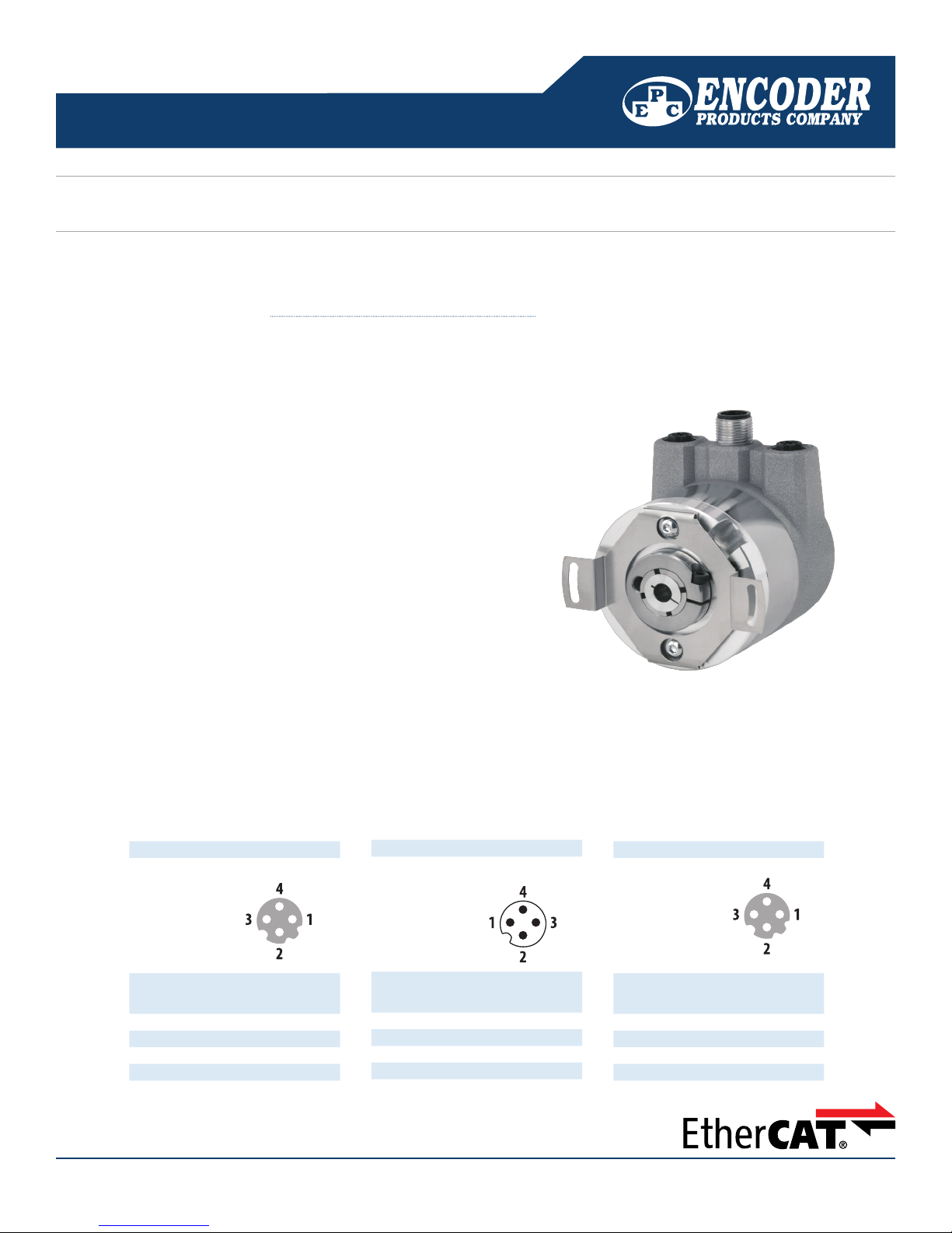
This technical bulletin will give you step-by-step instructions to get started with EPC’s Model A58E series of EtherCAT-ready absolute encoders. You will
learn how connect the encoder, how to navigate to the encoder’s web page, and how to change the encoder IP address, subnet mask, and gateway
address. For more information, see the EtherCAT Interface Technical Reference Manual. at encoder.com.
Connect the Encoder
Step 1
Connect Port 1 to your EtherCAT master or EtherCAT coupler using a
M12x1, 4-pin, D-coded male to RJ-45 cable.
Step 2
Connect the power cable using a M12x1, 4-pin, A-coded female
connector.
1
2
3
Step 3
(Optional) Connect Port 2 to another EtherCAT device in your network
using a M12x1, 4-pin, D-coded male connector to another EtherCAT
slave device or Ethernet switch.
Step 4
Refer to procedure on the reverse side for communication with the
EtherCAT encoder.
1 Ethernet Port 1
2 Power connection
3 Ethernet Port 2
1-800-366-5412 | www.encoder.com | sales@encoder.com
ENCODER PRODUCTS COMPANY TB-542, REV. A, 12/2018
PAGE 1 of 2
TECHNICAL BULLETIN
TB-542: Model A58E Series Quick Installation Guide
Getting Started with the Model A58E Series of EtherCAT-Ready Absolute Encoders
Step 1. Activate the encoder.
This step is necessary to put the encoders into an operational state. Without activation
the encoder cannot communicate over the EtherCAT network.
Procedure – Start your EtherCAT master controller.
Follow the instructions provided with your EtherCAT master to activate slave devices
on the network. Check that the EtherCAT state is OP (Operational).
Optional Additional Instructions – Steps to access the encoder web page are
below.
These steps are needed when provisioning the encoder or when conguring multiple
encoders on the network. The example shown is for a PC EtherCAT master. Please
contact your network administrator for assistance.
NOTE: All encoders ship with a default IP address of 192.168.1.127
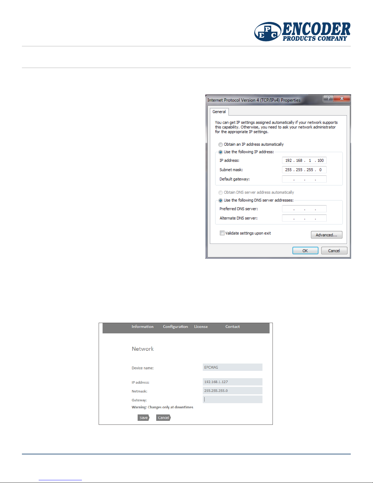
Step 2. Change PC EtherCAT master IP address.
Procedure – Set your EtherCAT master or computer IP address to 192.168.1.100, set
Subnet mask to 255.255.255.0
Note: The IP address may be any IP address on the 192.168.1.x network, except .127
Step 3. Browse to the EPCMAG encoder web page
Procedure – Open a web browser and type the following command:
http://192.168.1.127
Figure 1
Step 4. Change encoder IP address and Netmask
Procedure – Navigate to the Conguration -> Network page
Enter new values for the IP address and Netmask.
Click the Save button. The new network values will automatically be saved to the encoder. Allow 10 seconds for the new settings to take eect.
Note: A gateway address is needed only if you want to route packets to external Ethernet networks. Contact your network administrator for assistance.
Troubleshooting
1. If you cannot view the encoder web page, check the network connection by typing the following command in a terminal window: ping 192.168.1.127
No response or dropped packets indicates a problem with your network connection/conguration.
1-800-366-5412 | www.encoder.com | sales@encoder.com
Figure 2
PAGE 2 of 2
ENCODER PRODUCTS COMPANY TB-542, REV. A, 12/2018
 Loading...