

ENCAD T-200 Service Manual
SERVICE MANUAL

CADJET® T-200
COLOR INKJET
PRINTER/PLOTTER
SERVICE MANUAL
Part Number 219863-00
®

iii
CadJet T-200 Service Manual
Copyright Eastman Kodak Company, 2002
KODAK, ENCAD
®
and CadJet® are trademarks of
Eastman Kodak Company.
Other trademarks and registered trademarks are the
property of their respective owners.
Except as provided below, no part of this manual may be
copied or distributed, transmitted, transcribed, stored in
a retrieval system, or translated in any human or computing language, in any form or by any means, electronic,
mechanical, magnetic or otherwise, or disclosed to a
third party without the express written permission of
ENCAD, Inc., 6059 Cornerstone Court West, San Diego,
CA 92121, U.S.A.
Certain manuals developed by ENCAD are in an electronic format to be distributed on CDs or over the
internet. The registered user of an ENCAD product
whose manual is distributed in this fashion may print one
copy for their personal use only.
Printing history
1st Edition Rev A October 2002

iv
CadJet T-200 Service Manual
FCC Statement (U.S.A.)
The United States Federal Communications Commision has specified that
the following notice be brought to the attention of the users of the CADJET
T-200 printer.
FEDERAL COMMUNICATIONS COMMISION RADIO AND TELEVISION
INTERFERENCE FOR CLASS B DEVICE
This equipment has been tested and found to comply with the limits for a
class B digital device, pursuant to part 15 of the FCC Rules. These limits
are designed to provide reasonable protection against harmful interference
in a residential installation. This equipment generates, uses, and can
radiate radio frequency energy and, if not installed and used in accordance
with the instructions, may cause harmful interference to radio communications.
User Instructions:
If the equipment does cause harmful interference to radio or television
reception, which can be determined by turning the equipment off and on,
the user is encouraged to try to correct the interference by one of the
following measures:
• Reorient or relocate the receiving antenna.
• Increase the separation between the equipment and receiver.
• Connect the equipment into an outlet on a circuit different from
that to which the receiver is connected.
• Consult the dealer or an experienced radio/TV technician for
help.
Changes or modifications not expressly approved by ENCAD, Inc. could
void the user’s authority to operate the equipment.

v
CadJet T-200 Service Manual
VDE Statement
Hiermit wird bescheinigt, daß der CADJET T-200 in Übereinstimmung mit
den Bestimmungen der BMPT-AmstbIVfg 234/1991 funkentstört ist. Der
vorschriftsmäßige Betrieb mancher Geräte (z.B. Meßsender) kann
allerdings gewissen Einschränkungen unterliegen. Beachten Sie deshalb
die Hinweise in der Bedienungsanleitung.
Dem Zentralamt für Zulassungen im Fernmeldewesen würde dan
Inverkehrbringen dieses Gerätes angezeigt und die Berechtigung zur
Überprüfung der Serie auf die Einhaltung der Bestimmungen eingeräumt.
ENCAD, Inc. U.S.A

vi
CadJet T-200 Service Manual
Material Safety Data Sheet
ENCAD QIS (Quality Imaging Supplies) ink is nonhazardous, requiring no
special disposal handling. It can be harmful if swallowed and should be
kept away from children.
To obtain a Material Safety Data Sheet, contact ENCAD, Inc. at:
6059 Cornerstone Court West
San Diego, CA 92121-3734
(858) 452-4350
International users should contact their local dealer or distributor.

vii
CadJet T-200 Service Manual
WARRANTY OR DAMAGE CLAIMS
United States
ENCAD®, Inc., warrants its printers ("PRODUCT") to be free from defects in workmanship
and materials for a period of one year from the date of purchase. In order to submit a
Warranty claim, please contact the ENCAD Help Desk at (619) 452-4350.
ENCAD reserves the right to make changes or improvements to Products, without incurring
any obligation to similarly alter Products previously purchased.
Buyer's sole and exclusive rights pursuant to this Warranty shall be for the repair or
replacement of defective Product. ENCAD specifically disclaims any and all other warranties, expressed or implied, including but not limited to, implied warranties of merchantability
and fitness for a particular purpose. In no event shall ENCAD be liable for any loss of
profit or other commercial damages, special, incidental or consequential damages, or any
other damages or claims, whatsoever.
This Warranty gives Buyer specific legal rights, and Buyer may also have other rights that
vary from state to state.
This Warranty applies only to printers purchased from ENCAD, or authorized ENCAD
distributors or dealers. The intent of this Warranty is to repair or replace defective Products subjected to normal wear and tear, when operated according to ENCAD instructions.
This Warranty does not cover damage to the Product resulting from the following:
• Accident or negligence.
• Unauthorized modification of the Product.
• Adverse environmental conditions.
• Service of the Product by other than an ENCAD authorized service provider.
• Unauthorized or improper use, including but not limited to:
– Use in applications for which the Product was not designed.
– Using cartridges or ink other than those supplied by ENCAD or authorized
ENCAD resellers.
– Using media other than that supplied by ENCAD or authorized ENCAD
resellers.
– Lubricating any part of the printer.
Internationally: Contact your dealer or distributor for warranty information.

viii
CadJet T-200 Service Manual
Table of Contents
Chapter 1 General Description ............................................................ 1-1
Introduction ............................................................................................................... 1-1
Overview ................................................................................................................... 1-3
Related Publications .......................................................................................... 1-3
Electrostatic Discharge (ESD) Sensitivity ................................................................. 1-3
Warnings, Cautions and Notes ................................................................................. 1-4
Printer Specifications ................................................................................................ 1-5
Contents of this Service Manual ................................................................................ 1-6
Technical Support ..................................................................................................... 1-8
Chapter 2 Theory of Operation ............................................................ 2-1
Introduction ............................................................................................................... 2-1
CadJet T-200 Printer General Block Diagram ............................................................ 2-1
Paper (Media) Axis Drive .......................................................................................... 2-3
The Carriage Axis Drive ............................................................................................. 2-4
Main Printed Wiring Assembly (MPWA) ................................................................... 2-5
Microprocessor .................................................................................................. 2-6
Gate Array ......................................................................................................... 2-6
Memory Circuits ................................................................................................. 2-7
Flash EEPROM ........................................................................................... 2-7
DRAM .......................................................................................................... 2-8
Serial EEPROM ........................................................................................... 2-8
Stepper Motor Controller ..................................................................................... 2-9
Servo Motor Controller ...................................................................................... 2-11
Control Panel ................................................................................................... 2-13
Interface Circuits: Serial & Parallel ................................................................... 2-14
Carriage Assembly Circuits ..................................................................................... 2-15
Display Assembly ................................................................................................... 2-16
Power Supply ......................................................................................................... 2-17
Fan Operation ......................................................................................................... 2-17
Chapter 3 Maintenance ........................................................................ 3-1
Introduction ............................................................................................................... 3-1
Scheduled Maintenance ........................................................................................... 3-1
Cleaning Procedures .......................................................................................... 3-2
External Cleaning ......................................................................................... 3-2

ix
CadJet T-200 Service Manual
Slide Shaft Cleaning ..................................................................................... 3-2
Service Station Cleaning .............................................................................. 3-3
Linear Encoder Strip Cleaning ...................................................................... 3-4
Cartridge Dimples Cleaning .......................................................................... 3-5
Flex Cable Contact Cleaning ........................................................................3-6
Clean and Inspect Stepper Motor Gears....................................................... 3-7
Clean and Inspect MPWA ............................................................................ 3-7
Clean and Inspect Carriage Assembly ......................................................... 3-8
Reseat Connectors on MPWA and Carriage Board ............................................. 3-8
Replace Carriage Bushings .............................................................................. 3-11
Servo Motor Winding Resistance Check ................................................................. 3-12
Stepper Motor Winding Resistance Check .............................................................. 3-13
Banding: Hardware vs Software ............................................................................... 3-14
Common Banding Causes ......................................................................... 3-15
Alignments/Adjustments ......................................................................................... 3-17
Slide Shaft Profile Adjustment .......................................................................... 3-17
Head Height Alignment Procedure .................................................................... 3-20
Paper Skew Adjustment ................................................................................... 3-24
Paper Skew Adjustment Sequence ............................................................ 3-24
Mounting Screw Information ....................................................................... 3-25
Other Functional Requirements .................................................................. 3-28
Adjustment of Pinch Roller Supports .......................................................... 3-29
Visual Verification ................................................................................ 3-29
Observation of Paper Skew at Rear Media Alignment Mark .................. 3-30
Observation of Paper Skew at Front Media Alignment Mark ................. 3-31
Adjustment of the Mounting Screws .................................................... 3-32
Paper Axis Calibration ...................................................................................... 3-33
Deadband Alignments ....................................................................................... 3-35
Color Deadband Alignment ......................................................................... 3-36
Color Calibration ............................................................................................... 3-38
Diagnostics Menu ................................................................................................... 3-40
Clearing the NVRAM ............................................................................................... 3-42
Firmware Download/Upgrading for the PC ............................................................... 3-43
Internal Cabling and Signal Flow Diagrams ............................................................. 3-44
Table of Contents (cont)
Chapter 3 Maintenance (cont)

x
CadJet T-200 Service Manual
Chapter 4 Troubleshooting .................................................................. 4-1
Introduction ............................................................................................................... 4-1
No Power ........................................................................................................... 4-1
Initialization Failure............................................................................................. 4-2
Media Does Not Move ........................................................................................ 4-2
Internal ERROR “Carriage Axis Failure” .............................................................. 4-3
Internal ERROR “Encoder Sensor Failure” .......................................................... 4-5
Internal ERROR “Paper Sensor Failure” .............................................................. 4-5
Internal ERROR “Auto-Sensor Failure” ................................................................4-6
Internal ERROR “MPCB Failure” ......................................................................... 4-6
Unrecognized Cartridges Error ............................................................................ 4-6
Image Skews or Moves ...................................................................................... 4-7
Does Not Print.................................................................................................... 4-7
Ink Cartridge Misfiring ......................................................................................... 4-7
Paper Skewing ................................................................................................... 4-9
Printer Output is Banding (Horizontal) ................................................................ 4-9
Printer Output is Banding (Vertical) .................................................................. 4-11
Printer Output is Banding (Horizontally and Vertically) ...................................... 4-12
Keypad Locked-Up or Not Functioning Properly ............................................... 4-12
Noisy Operation ............................................................................................... 4-13
Line Quality Degraded ...................................................................................... 4-14
Fan Does Not Power Up ................................................................................... 4-15
Media is Not Measured Properly ...................................................................... 4-15
Initialization Troubleshooting ................................................................................... 4-16
Chapter 5 Assembly\Disassembly ...................................................... 5-1
Introduction ............................................................................................................... 5-1
Removing the Right Cover Assembly ......................................................................... 5-2
Removing the MPWA Connectors ............................................................................. 5-4
Removing the MPWA ............................................................................................... 5-5
Removing the Right SidePlate ...................................................................................5-6
Reinstalling the Right SidePlate ................................................................................5-7
Reinstalling the MPWA............................................................................................. 5-7
Reinstalling the MPWA Connectors .......................................................................... 5-7
Table of Contents (cont)

xi
CadJet T-200 Service Manual
Memory Module Removal ..........................................................................................5-8
Memory Module Installation ...................................................................................... 5-9
Reinstalling the Right Cover Assembly ...................................................................... 5-9
Removing the Left Cover ........................................................................................... 5-9
Reinstalling the Left Cover....................................................................................... 5-10
Removing the Servo Motor ...................................................................................... 5-10
Reinstalling the Servo Motor ................................................................................... 5-12
Removing the Display Assembly ............................................................................. 5-13
Reinstalling the Display Assembly .......................................................................... 5-14
Removing the Service Station Assembly ................................................................. 5-14
Reinstalling the Service Station Assembly .............................................................. 5-15
Removing the Carriage Assembly, Carriage Belt and the Frame Tensioner ............. 5-16
Removing the Carriage PWA................................................................................... 5-20
Reinstalling the Carriage PWA................................................................................ 5-21
Remove the Paper Sensor or the Encoder Sensor .................................................. 5-21
Install the Paper Sensor or the Encoder Sensor...................................................... 5-23
Replacing the Carriage Bushings ............................................................................ 5-24
Reinstalling the Carriage Assembly, Carriage Belt and the Frame Tensioner .......... 5-26
Removing the Trailing Cable .................................................................................... 5-28
Reinstalling the Trailing Cable ................................................................................. 5-29
Removing the Power Supply and ON/OFF Switch ................................................... 5-30
Reinstalling the Power Supply and ON/OFF Switch ................................................ 5-32
Remove the Stabilizer Bracket and Encoder Strip ................................................... 5-33
Install the Stabilizer Bracket and Encoder Strip....................................................... 5-34
Disassembly of Plotter Before Removing the Inner Platen Parts .............................. 5-35
Removing the Inner Platen Parts ............................................................................. 5-37
Removing the Stepper Motor ................................................................................... 5-39
Reinstalling the Stepper Motor ................................................................................ 5-41
Reinstalling the Inner Platen Parts .......................................................................... 5-41
Reassembly of Plotter After Reinstalling the Inner Platen Parts............................... 5-43
Removing the Upper Pinch Roller Supports ............................................................. 5-44
Reinstalling the Upper Pinch Roller Supports .......................................................... 5-46
Chapter 6 Parts List .............................................................................. 6-1
Table of Contents (cont)
Chapter 5 Assembly/Disassembly (cont)

xii
CadJet T-200 Service Manual
List of Illustrations
Figure Page
Chapter 1 General Description
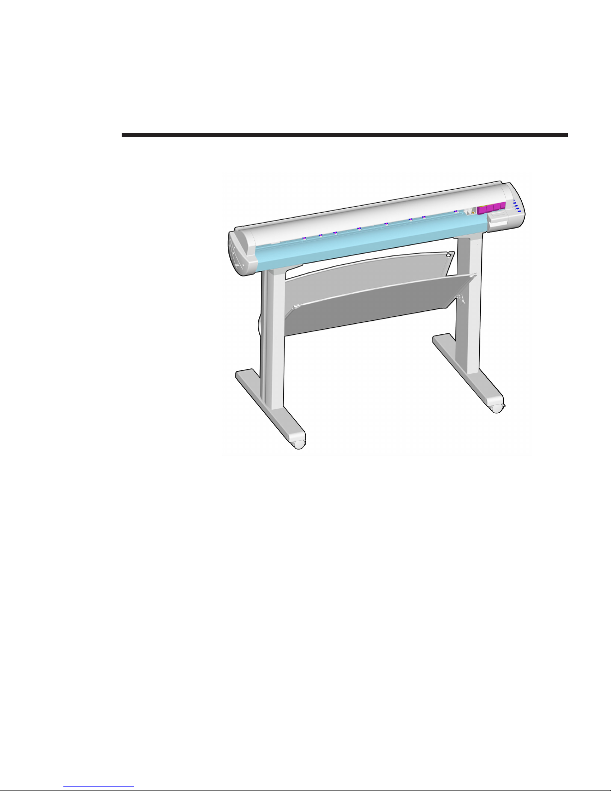
1-1. CadJet T-200 Inkjet Printer/Plotter ................................................................... 1-1
Chapter 2 Theory of Operation
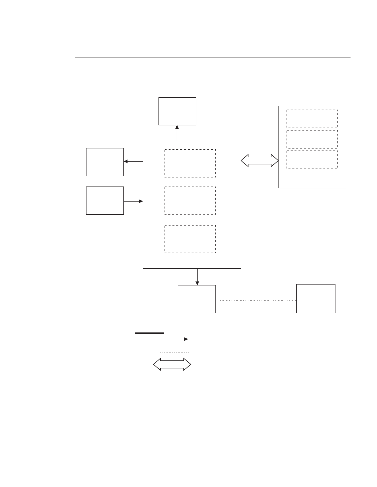
2-1. General Block Diagram ................................................................................... 2-2
2-2. Paper (Media) Axis Drive ................................................................................. 2-3
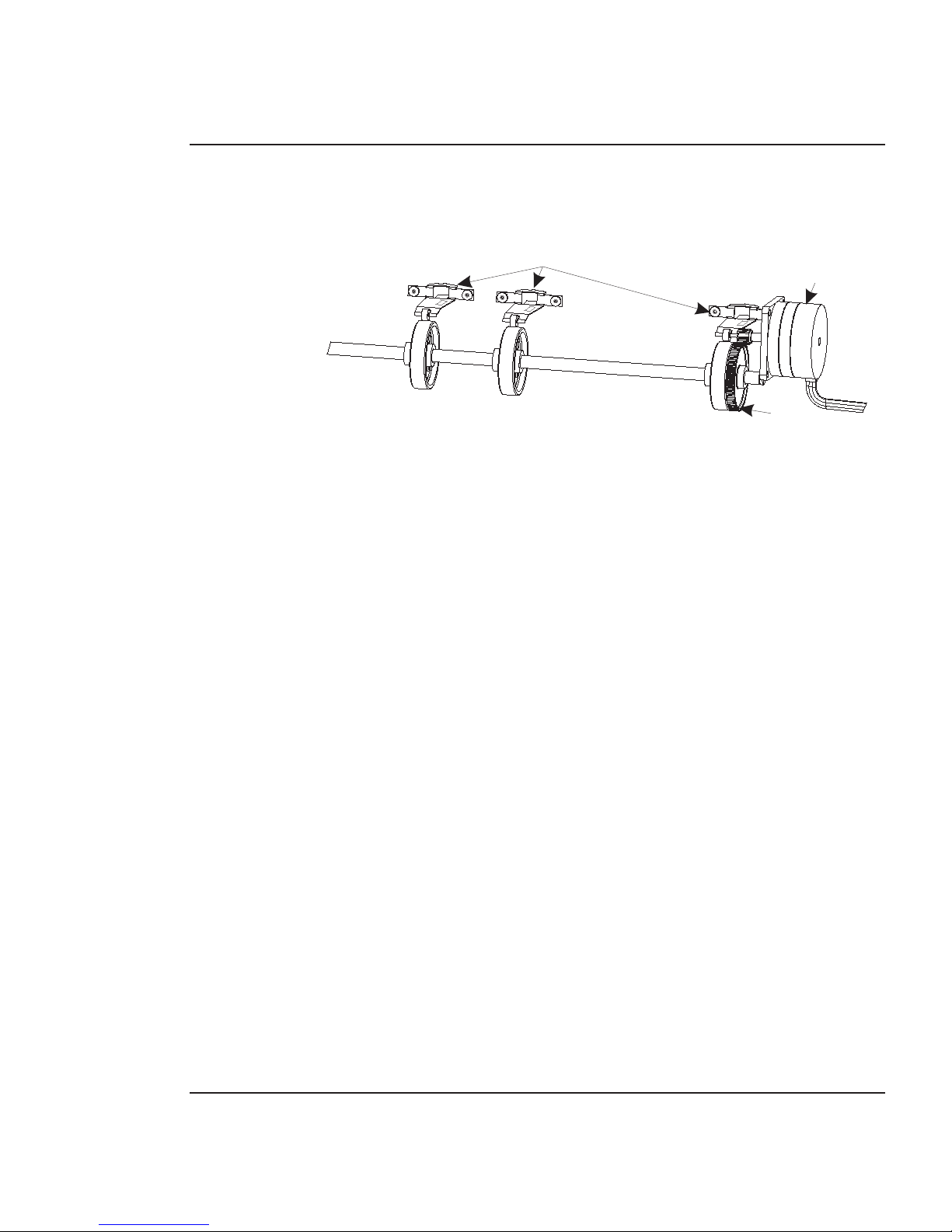
2-3. Carriage Axis Drive ..........................................................................................2-4
2-4. Main Printed Wiring Assembly ........................................................................ 2-5
2-5. Gate Array ...................................................................................................... 2-6
2-6. Stepper Motor Controller ................................................................................. 2-9
2-7. Servo Motor Controller ................................................................................... 2-11
2-8. Quadrature Signal Generation ....................................................................... 2-12
2-9. Control Panel ................................................................................................ 2-13
2-10. Interface Circuits ........................................................................................... 2-14
2-11. Carriage Assembly Circuits ........................................................................... 2-15
2-12. Display Assembly ......................................................................................... 2-16
Chapter 3 Maintenance
3-1. Encoder Strip Cleaning ................................................................................... 3-5
3-2. Cartridge Dimple Region ..................................................................................3-5
3-3. Flex Cable Contacts ....................................................................................... 3-6
3-4. Main PWA Connection Locations .................................................................... 3-9
3-5. Carriage PWA Connection Locations............................................................. 3-10
3-6. Ribbon Connector Locking Mechanism ......................................................... 3-11
3-7. Servo Motor ................................................................................................... 3-12
3-8. Stepper Motor ............................................................................................... 3-13
3-9. Examples of Banding .................................................................................... 3-14
3-10. Dial Gauge Micrometer Assembly ................................................................. 3-18
3-11. Measurement Positions for Slide Shaft.......................................................... 3-19
3-12. Slide Shaft Profile Adjustment ....................................................................... 3-19
3-13. Carriage Head Height Tolerance .................................................................... 3-20
3-14. Setting Up Tools from Height Gauge Kit ........................................................ 3-21
3-15. Zeroing the Micrometer Gauge ...................................................................... 3-21

xiii
CadJet T-200 Service Manual
List of Illustrations (cont)
Figure Page
Chapter 3 Maintenance (cont)
3-16. Test Cartridge Installed .................................................................................. 3-22
3-17. Pinch Roller Supports Numbering Sequence ................................................. 3-24
3-18. Pinch Roller Support and Mounting Screws ................................................... 3-26
3-19. Correct Positioning of the Spring in the Pinch Roller Support......................... 3-27
3-20. Test for Minimum Acceptance Gap ................................................................ 3-28
3-21. Visual Verification of Gap between Roller and Y-Arm ..................................... 3-29
3-22. Paper Skew Acceptance Range for Rear Media Alignment Mark ................... 3-30
3-23. Paper Skew Acceptance Range for Front Media Alignment Mark .................. 3-31
3-24. Motion of Rollers and Adjustment of Mounting Screws .................................. 3-32
3-25. Paper Axis Test ............................................................................................. 3-34
3-26. Slow Deadband ............................................................................................. 3-35
3-27. Color Calibration ............................................................................................ 3-38
3-28. MPWA Connections Diagram ........................................................................ 3-45
3-29. Carriage PWA Connections Diagram ............................................................. 3-46
Chapter 4 Troubleshooting
4-1. Carriage Board LED D2 and D5 Locations ..................................................... 4-17
Chapter 5 Assembly/Disassembly
5-1. Removal of Right Cover Assembly ................................................................... 5-3
5-2. MPWA Connection and Screw Locations ........................................................ 5-4
5-3. Removal of Right Side Plate ............................................................................ 5-6
5-4. Removal of Left Cover .................................................................................... 5-10
5-5. Removal of the Servo Motor ........................................................................... 5-11
5-6. Compression of Frame Tensioner .................................................................. 5-12

xiv
CadJet T-200 Service Manual
List of Illustrations (cont)
Figure Page
Chapter 5 Assembly/Disassembly (cont)
5-7. Removal of Display Assembly ....................................................................... 5-13
5-8. Service Station Removal ................................................................................ 5-14
5-9. Electronics Cover Removal ............................................................................ 5-16
5-10. Strain Relief Removal/Installation................................................................... 5-17
5-11. Frame Tensioner ........................................................................................... 5-18
5-12. Carriage Belt Clamp ...................................................................................... 5-19
5-13. Carriage PWA Removal/Installation ............................................................... 5-20
5-14. Paper and Encoder Sensor Removal ............................................................. 5-22
5-15. Paper and Encoder Sensor Installation .......................................................... 5-23
5-16. Carriage Bushing Removal ............................................................................ 5-25
5-17. Carriage Bushing Installation ......................................................................... 5-26
5-18. Revealing the Power Supply Screws ............................................................. 5-31
5-19. Inner Platen Parts ......................................................................................... 5-32
5-20. Stabilizer Bracket Removal............................................................................ 5-34
5-21. Disassembly of Plotter Prior to Removing the Inner Platen Parts ................... 5-36
5-22. Removal of Lower Drive Shaft Screws ............................................................ 5-37
5-23. Removing the Foam Block ............................................................................ 5-38
5-24. Lower Drive Shaft Assembly and Stepper Motor Assembly ............................ 5-40
5-25. Removing the Upper Pinch Roller Support ..................................................... 5-45
Chapter 6 Parts List
6-1. Left Side Parts Breakdown .............................................................................. 6-3
6-2. Platen and Above Parts Breakdown ................................................................ 6-5
6-3. Right Side Parts Breakdown ........................................................................... 6-7
6-4. Inner Platen Parts Breakdown ......................................................................... 6-9
6-5. Carriage Assembly Parts Breakdown ............................................................ 6-11
6-6. Service Station Assembly Parts Breakdown .................................................. 6-13

xv
CadJet T-200 Service Manual
List of Tables
Table Page
Chapter 1 General Description
Chapter 2 Theory of Operation
Chapter 3 Maintenance
3-1. Main PWA Connections Table ......................................................................... 3-9
3-2. Carriage PWA Connections Table .................................................................. 3-10
Chapter 4 Troubleshooting
4-1. Troubleshooting Table ...................................................................................... 4-1
Chapter 5 Assembly/Disassembly
Chapter 6 Parts List
1
1-1
General Description
Figure 1-1. CadJet T-200 Inkjet Printer/Plotter.
Introduction
This manual provides service information for the ENCAD®, Inc. 36
inch CadJet T-200 Color Inkjet Printer/Plotters.
It is written for service personnel who possess analog and digital
circuitry experience. Chapter 2, Theory of Operation, should be read
and thoroughly understood before troubleshooting/calibrating the
printers.
The printers support both pre-cut and roll media. Media size is auto-
matically determined and hardclip limits are set accordingly. Pre-cut

General Description 1-2
CadJet T-200 Service Manual
media uses different maximum plotting areas than roll media. See the
Printer Specifications in the User Guide for more details on the media
size printable area.
A Centronics parallel connection is provided to interface with the host
computer. Network connections are made possible through the optional
SEH print server. Commands sent from the host computer can be in
several forms including HP-GL/2, HP-RTL and EN-RTL formats.
Drivers are supplied to support Windows-based PC’s (3.XX, 95/98, and
NT) as well as Macintosh and Power PC computers.
These printers expand upon ENCAD’s tradition of delivering fast, high-
quality color or monochrome graphics for a variety of applications.
ENCAD has made significant advances in designing these printers to
respond to and anticipate our customers’ needs. Principal features are
summarized below.
Locally or Remotely Configured via Host Computer
Take-Up Basket
PowerPC 33 MHz Microprocessor
8 User Configurable Settings
208 Jet Foam Filled Ink Cartridges
Ink Priming System
Snap On Ink Cartridge Caddies for longer print times between refilling
Smart Cartridges
Odometer Function
Electronic Jet Compensation
Fast CAD printing speeds

General Description 1-3
CadJet T-200 Service Manual
Overview
Printers draw according to instructions issued from a “host” computer.
Every printer is engineered to understand a specific set of instructions
and to execute each instruction in a precise manner. In addition, most
printers are designed to execute predetermined characters automati-
cally without a specific line-by-line instruction from the program.
These characters are part of the printer’s permanent memory.
Related Publications
The following publication contains additional information which may
be useful in servicing the ENCAD, Inc. CadJet T-200 Color Inkjet
Printers:
• ENCAD Quick Start Guide for the CadJet T-200,
P/N 217892-xx
• ENCAD CadJet T-200 CD-ROM,
P/N 217893-xx
Copies of these and other ENCAD, Inc. publications may be obtained
by contacting your nearest authorized ENCAD, Inc. dealer or by
contacting ENCAD’s Technical Support and Service Department.
Electrostatic Discharge (ESD) Sensitivity
All PWAs (Printed Wiring Assemblies) associated with the printers
have components sensitive to ESD (electrostatic discharge). Care must
be taken to avoid damage to any of the components by following
current ESD handling procedures and practices.
Always use an approved ESD grounding strap when handling or
working with PWAs.

General Description 1-4
CadJet T-200 Service Manual
Warnings, Cautions and Notes
Warnings, cautions and notes are used when additional information,
instructions or care should be observed. In this manual warnings,
cautions and notes precede the text to which each applies. The defini-
tion of each is provided below.
WARNINGS - Warnings are used to stress that the following steps or
procedures has the potential to cause serious harm or death to service
personnel. Extreme care should be observed when following the proce-
dures and to exercise standard safety procedures. They are indicated
by:
Followed by a paragraph describing the concern.
CAUTIONS - Cautions depict that the following steps or procedures can
cause damage to the equipment if not properly followed. Extreme care
should be observed when following the procedures and to exercise
standard safety procedures. They are indicated by:
CAUTION
Followed by a paragraph describing the concern.
NOTES - Notes are placed before a procedure to inform the service
personnel of specific details to improve quality, to give reminders of
interrelated parts and to provide other helpful information. They are
indicated by:
NOTE
Followed by a paragraph describing the concern.

General Description 1-5
CadJet T-200 Service Manual
Printer Specifications
The specifications and performance characteristics of the CadJet
T-200 Color Inkjet Printers are as follows:
Max Printing Area:
Norm 34.8”
884 mm
Extend 35.61”
904 mm
Language Emulation:
HP-RTL
EN-RTL
HP GL/2
Buffer:
32 MB installed
upgradeable to 128 MB
Power Requirements:
Input Voltage:
90-246 VAC
47-63 Hz
Output Power:
20 W idle
50 W typical
100 W maximum
Accuracy:
Dot Placement: 0.0017
+/- 0.0008
Cut sheet feed accuracy,
edge shift: +/- 0.065
inches as measured over
36 inches
Resolution:
600x600 dpi or
300x600 dpi
Interface:
Centronics parallel
(IEEE 1284)
Network: via 100 Base T
Print Server
Certifications:
Safety
CSA, CSE/NRTL
(equivalent to UL1950)
TUV GS
EN 50 082-1
EN 60 950
UL1950
NOM-019-SCFI-1993
IEC 950
AS/NZS 3260
EMI
FCC Class B
CSA C108.8
EN 55 022 Class B
CISPR 22- Class B
AS/NZS 3548
GB9254-98

General Description 1-6
CadJet T-200 Service Manual
Contents of this Service Manual
Figures are used in this manual to clarify procedures. They are for
illustrative purposes only and may not necessarily be drawn to scale.
Material in this manual may be repeated in various chapters so that
each chapter can “stand alone”. This allows information to be located
without having to refer back and forth between chapters.
Figures and tables are easily located and cross-referenced, and are listed
in the front of the manual under List of Illustrations and List of Tables.
This manual is divided into six chapters as:
Chapter 1 GENERAL DESCRIPTION - Contains a general
description of the ENCAD CadJet T-200 printer. This
includes printer specifications, and related materials. Also
included is a description of the use of Warnings, Cautions
and Notes as used in this manual and chapter contents.
Chapter 2 THEORY OF OPERATION - Functional
descriptions of the overall printer and major assemblies are
contained in this chapter.
Environment:
Operating:
41° to 85° F
(5° to 30° C)
20% to 80% RH
non-condensing
Storage:
-5° to 140° F
(-21° to 60° C)
5% to 80% RH
non-condensing
Weight:
70 lbs(31 kg)
Dimensions:
Height 48” (1210 mm)
Width 54” (1370 mm)
Depth 30” (710 mm)

General Description 1-7
CadJet T-200 Service Manual
Chapter 3 MAINTENANCE - This chapter covers the
scheduled maintenance, cleaning procedures and
alignment/adjustments recommended to perform on the
printers. Diagnostics and a signal flow diagram are also
listed.
Chapter 4 TROUBLESHOOTING - A table containing
problems that could occur and possible causes and repairs
is found in this chapter. This table is not intended to be a
complete listing of troubleshooting procedures. It will
isolate the problem down to the lowest replacable
assembly. If the problem happens to be the wiring
between assemblies, standard troubleshooting techniques
will have to be implemented to correct the problem.
Chapter 5 ASSEMBLY/DISASSEMBLY - Contains detailed
procedures to remove and replace printer parts and
assemblies.
Chapter 6 PARTS LIST - Contains a complete listing of all
field replacable parts and assemblies for the color inkjet
printers. Illustrated parts breakdown drawings are
included to help clarify and identify parts for ordering.
Special kits and adjustment jigs may also be required.
ORIENTATION - Instructions in this manual are based on the
assumption that the service person is facing the front of the printer.
References to top view, back view, and so forth are consistent with
this engineering standard. References to the X Axis and Y Axis
(Paper Axis and Carrier Axis, respectively) follow the standard of
AutoCAD™ absolute coordinates: up and down for X, left to right for
Y.

General Description 1-8
CadJet T-200 Service Manual
Technical Support
ENCAD offers full technical support and service for its various prod-
ucts. If you are unable to find the answer to your question in either the
User’s Guide, Service Manual, or other related publications, check out
ENCAD’s Knowledge Base located on ENCAD’s website support:
ENCAD Website: http://www.encad.com
Additional information is available though our Technical Support and
Service Department’s Help Desk.
ENCAD, Inc.
Technical Support & Service Dept.
6059 Cornerstone Court West
San Diego, CA 92121
Help Desk Telephone: (858) 452-4350 or
(877) ENCAD-TS (362-2387)
Help Desk FAX: (858) 558-4672
International users contact your local ENCAD service provider. See
details on your ENCAD registration card.

2
2-1
Introduction
This chapter explains the mechanical and electrical theory of operation
of the ENCAD CadJet T-200 color inkjet printers.
The CadJet T-200 is a PowerPC 33MHz microprocessor-based digital
printer that receives plotting instructions from a host computer
through the Centronics parallel interface. This interface is either
connected directly to a computer or through a network print server.
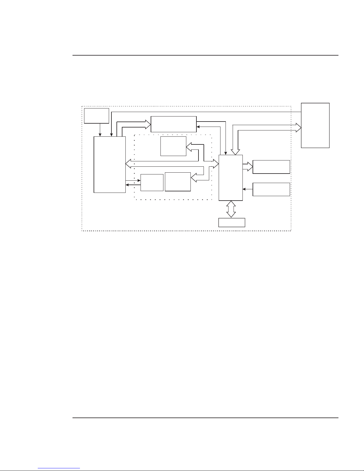
CadJet T-200 Printers General Block
Diagram
Figure 2-1 illustrates the major functional areas of the printers.
The CadJet T-200 printers consist of two mechanical assemblies:
1. Paper (Media) Axis Drive
2. Carriage Axis Drive
and four main electrical assemblies:
1. MPWA (Main Printed Wiring Assembly)
2. Carriage Assembly
3. Display Assembly
4. Power Supply
Theory of Operation
Theory of Operation 2-2
CadJet T-200 Service Manual
CARRIAGE AXIS DRIVE
ELECTRICAL CONNECTION
MECHANICAL CONNECTION
MAIN DATA BUS
MPWA
DISPLAY
CIRCUITS
STEPPER
MOTOR
SERVO
MOTOR
MICRO-
PROCESSOR
MEMORY
CIRCUITS
GATE
ARRAY
CARRIAGE
ASSEMBLY
CARRIAGE
PWA
PAPER
SENSOR
LOWER
DRIVE
ASSEMBLY
LEGEND
ENCODER
SENSOR
PAPER AXIS DRIVE
POWER
SUPPLY
Figure 2-1. General Block Diagram.
Theory of Operation 2-3
CadJet T-200 Service Manual
Paper (Media) Axis Drive
LOWER ROLLER SHAFT ASSY
PINCH ROLLERS
STEPPER MOTOR
REDUCTION GEAR
Figure 2-2. Paper (Media) Axis Drive.
The Paper (Media) Axis Drive moves the plotting media in a direction
perpendicular to the length of the printer. This friction drive utilizes a
micro-step drive technology and consists of a stepper motor, reduction
gears, lower drive shaft assembly, and pinch rollers. This can be seen
in Figure 2-2.
The reduction gear meshes the stepper motor to the lower drive shaft
assembly which allows the media to advance or retract. The purpose of
the pinch rollers is to apply pressure to the media onto the drive shaft
assembly to reduce the chance of slipping.
Misaligned pinch wheels is a main cause of skewing the media. When
skewing occurs, pinch roller alignment may be required.
Theory of Operation 2-4
CadJet T-200 Service Manual
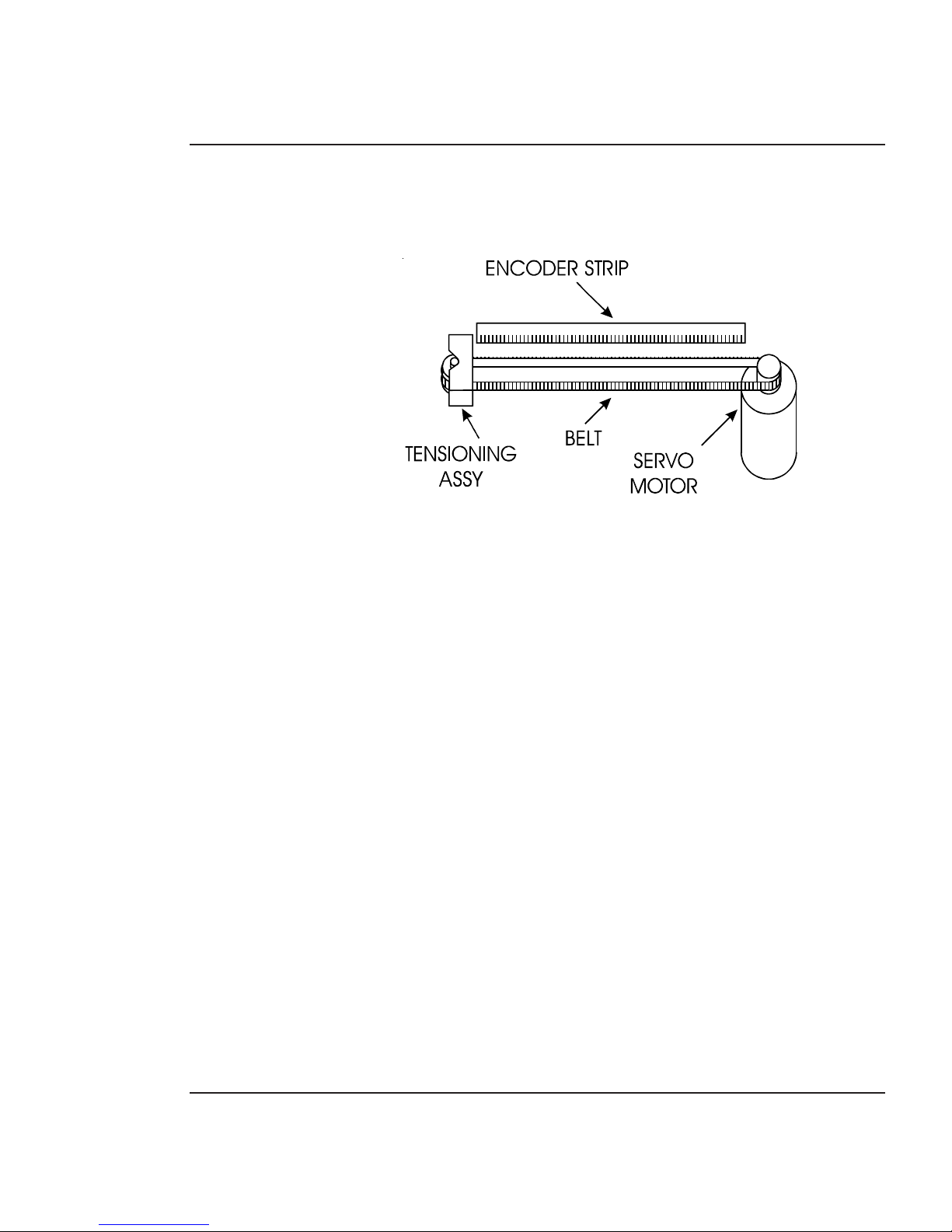
The Carriage Axis Drive
Figure 2-3. Carriage Axis Drive.
The Carriage Axis Drive moves the printer’s carriage assembly along
the length of the printer. The drive consists of a servo motor, linear
encoder strip, drive belt, and tensioning assembly. These items are
illustrated in Figure 2-3.
The servo motor, drive belt, and tensioning assembly are the compo-
nents that actually drive the carriage assembly. The servo motor drives
the belt back and forth allowing the attached carriage assembly to be
repositioned as required. The tensioning assembly is spring controlled
and allows the proper amount of tension on the belt.
The linear optical encoder strip is used to obtain the printers accuracy
along the axis of the printer. It is made with 150 parallel lines per inch
etched into it. By utilizing two optical encoder sensors that are slightly
off set from each other, and reading the leading and trailing edges of the
lines, a resolution of 600 dpi can be obtained.
The stepper and servo motors are controlled from the main printed
wiring assembly by the microprocessor.
Theory of Operation 2-5
CadJet T-200 Service Manual
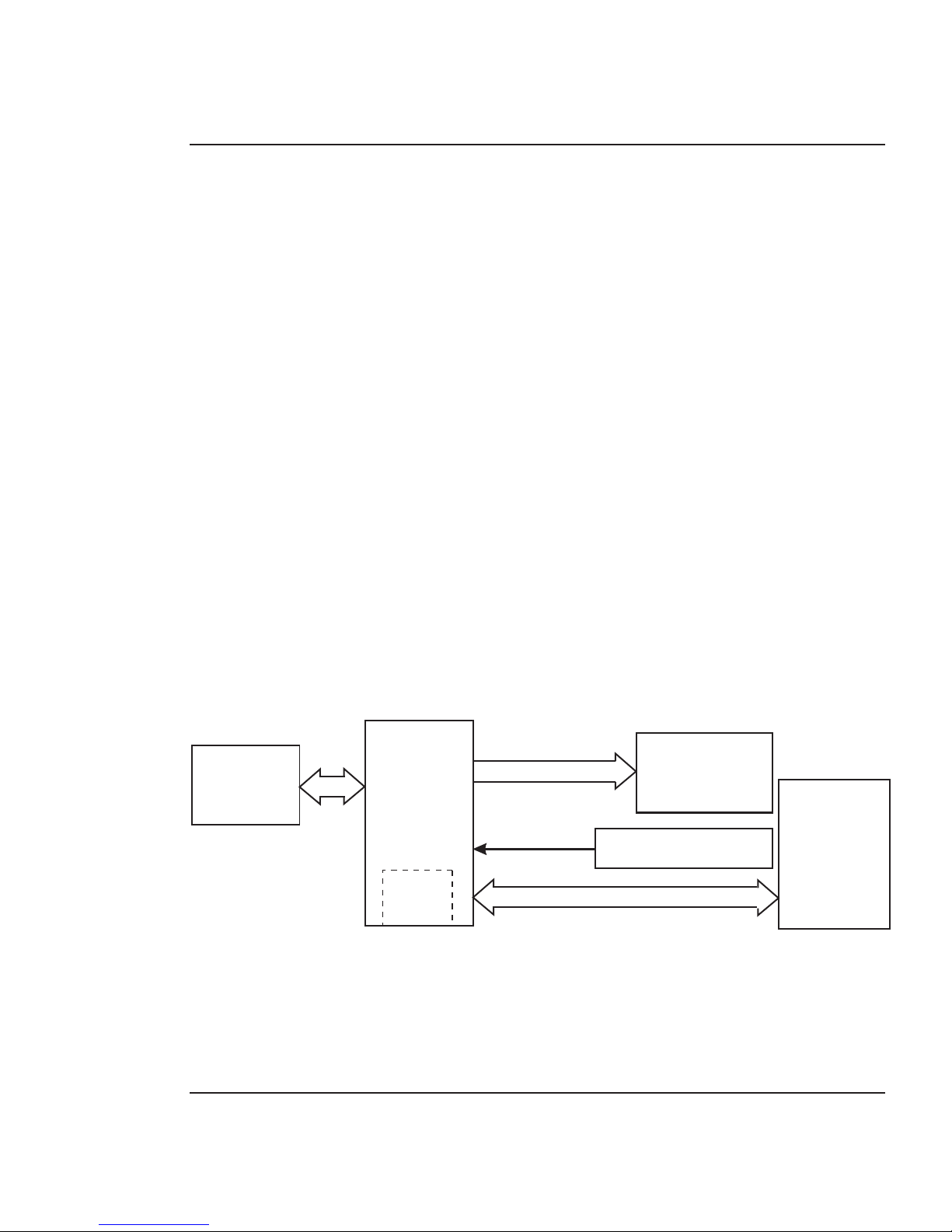
Main Printed Wiring Assembly (MPWA)
SERIAL
EEPROM
MICRO-
PROCESSOR
(CPU)
OSC
Y1
STEPPER MOTOR
CONTROLLER
FLASH
EEPROM
DYNAMIC
RAM
GATE
ARRAY
SERVO MOTOR
CONTROLLER
CARRIAGE
PWA
PARALLEL
DATA BUS
MEMORY CIRCUITS
CONTROL
PANEL
Figure 2-4. Main Printed Wiring Assembly.
The Main Printed Wiring Assembly (MPWA) consists of seven func-
tional areas:
1. Microprocessor (CPU)
2. Gate Array
3. Memory Circuits
4. Stepper Motor Controller
5. Servo Motor Controller
6. Control Panel
7. Interface Circuits: Parallel
Theory of Operation 2-6
CadJet T-200 Service Manual
Microprocessor
The microprocessor (an IBM PowerPC) is the central processor unit
which supervises system functions, executes the printer firmware,
manipulates data, and controls input/output data busses. It has two
built-in serial ports, a two channel DMA (Direct Memory Access)
controller, a timer module, clock generator, and an on-board chip select
generator. One serial port connects to the Mini-DIN connector which
can be used to communicate with the host computer; the other serial
port interfaces to the Control Panel. One DMA channel supplies data to
the gate array for jet firing; the other DMA channel is used to receive
data through the parallel port via the gate array, or the serial port
when using a high speed serial mode. One timer generates a servo
interrupt every millisecond; the other is used for timing the Stepper
Motor.
The system is timed by a 33MHz system clock from an oscillator (Y1).
The chip select generator is programmed to generate chip selects at the
appropriate addresses, with the appropriate data size (byte, word) and
with the appropriate number of wait states.
Gate Array
PARALLEL
PORT
GATE
ARRAY
SERVO
CONTROLLER
TO
CARRIAGE
PWA
STATIC
RAM
MICROSWITCHES
Figure 2-5. Gate Array.

Theory of Operation 2-7
CadJet T-200 Service Manual
The gate array contains the hardware logic for dot firing, monitoring
changes in the Carriage Assembly position, controlling DMA through
the parallel port, receiving commands from the microswitches and
generating the PWM (Pulse Width Modulation) waveforms for the
servo controller.
The gate array is a Xilinx device. It is a static RAM-based field
programmable gate array. This means that the logic that it imple-
ments is determined by configuration information in internal RAM
storage. Each time power is turned on, this information must be
downloaded from the system ROM. This type of gate array allows for
the flexibility of upgrading the logic by simply downloading the new
system software.
Memory Circuits
Memory is used to retain large amounts of information. This infor-
mation is stored in the device memory in the form of binary bits.
Printer memory consists of Flash, DRAM, and EEPROM.
Maximum installable memory is as follows:
DRAM = 32 MB
Flash = 1 MB
Serial EEPROM = 1KB
Flash EEPROM
Flash EEPROM is Electrically Erasable, Programmable, Read Only
Memory used to store instructions and data constants which the
microprocessor can access and interpret, with no loss of information
when power is off.
 Loading...