

ENCAD 60e, 42e, NOVAJET PROe Service Manual

SER VICE MANUAL
60e
42e
P R I N T I N G
TM

This Page Intentionally Left Blank

NOVAJET® PROe
SERIES
COLOR INKJET
PRINTER
SERVICE MANUAL
Part Number 209053
®

4
Novajet PROe Series Service Manual
Copyright © 1997 ENCAD®, Inc. All rights reserved.
ENCAD is a registered trademark of ENCAD, Inc.
NOV AJET PRO™ is a trademark of ENCAD, Inc.
Other trademarks and registered trademarks are the
property of their respective owners.
No part of this manual may be copied or distributed,
transmitted, transcribed, stored in a retrieval system, or
translated in any human or computing language, in any
form or by any means, electronic, mechanical, magnetic or otherwise, or disclosed to a third party without
the express written permission of ENCAD, Inc., 6059
Cornerstone Court West, San Diego, CA 92121, U.S.A.
Printing history
1st Edition Rev A April 1997
2nd Edition Rev B June 1997

5
Novajet PROe Series Service Manual
FCC Statement (U.S.A.)
The United States Federal Communications Commision has specified
that the following notice be brought to the attention of the users of the
NOV AJET PROe series printers.
FEDERAL COMMUNICATIONS COMMISION RADIO AND TELEVISION INTERFERENCE FOR CLASS B DEVICE
This equipment has been tested and found to comply with the limits for a
class B digital device, pursuant to part 15 of the FCC Rules. These
limits are designed to provide reasonable protection against harmful
interference in a residential installation. This equipment generates,
uses, and can radiate radio frequency energy and, if not installed and
used in accordance with the instructions, may cause harmful interference to radio communications.
User Instructions:
If the equipment does cause harmful interference to radio or television
reception, which can be determined by turning the equipment off and on,
the user is encouraged to try to correct the interference by one of the
following measures:
• Reorient or relocate the receiving antenna.
• Increase the separation between the equipment and receiver.
• Connect the equipment into an outlet on a circuit different from
that to which the receiver is connected.
• Consult the dealer or an experienced radio/TV technician for
help.
Changes or modifications not expressly approved by ENCAD, Inc. could
void the user’s authority to operate the equipment.

6
Novajet PROe Series Service Manual
VDE Statement
Hiermit wird bescheinigt, daß der
NOV AJET PROe
in Übereinstimmung
mit den Bestimmungen der BMPT-AmstbIVfg 234/1991 funkentstört ist.
Der vorschriftsmäßige Betrieb mancher Geräte (z.B. Meßsender) kann
allerdings gewissen Einschränkungen unterliegen. Beachten Sie
deshalb die Hinweise in der Bedienungsanleitung.
Dem Zentralamt für Zulassungen im Fernmeldewesen würde dan
Inverkehrbringen dieses Gerätes angezeigt und die Berechtigung zur
Überprüfung der Serie auf die Einhaltung der Bestimmungen
eingeräumt.
ENCAD, Inc.
U.S.A

7
Novajet PROe Series Service Manual
Material Safety Data Sheet
NOV AJET PRO e
QIS (Quality Image Supplies) ink is nonhazardous,
requiring no special disposal handling. It can be harmful if swallowed and
should be kept away from children.
To obtain a Material Safety Data Sheet, contact
ENCAD, Inc.
at:
6059 Cornerstone Court West
San Diego, CA 92121-3734
(619) 452-4350
International users should contact their local dealer or distributor.

8
Novajet PROe Series Service Manual
W ARRANTY OR DAMAGE CLAIMS
United States
ENCAD®, Inc., warrants its printers ("PRODUCT") to be free from defects in workmanship
and materials for a period of one year from the date of purchase. In order to submit a
Warranty claim, please contact the ENCAD Help Desk at (619) 452-4350.
ENCAD reserves the right to make changes or improvements to Products, without incurring
any obligation to similarly alter Products previously purchased.
Buyer's sole and exclusive rights pursuant to this Warranty shall be for the repair or
replacement of defective Product. ENCAD specifically disclaims any and all other warranties, expressed or implied, including but not limited to, implied warranties of merchantability
and fitness for a particular purpose. In no event shall ENCAD be liable for any loss of
profit or other commercial damages, special, incidental or consequential damages, or any
other damages or claims, whatsoever.
This Warranty gives Buyer specific legal rights, and Buyer may also have other rights that
vary from state to state.
This Warranty applies only to printers purchased from ENCAD, or authorized ENCAD
distributors or dealers. The intent of this Warranty is to repair or replace defective Products subjected to normal wear and tear, when operated according to ENCAD instructions.
This Warranty does not cover damage to the Product resulting from the following:
• Accident or negligence.
• Unauthorized modification of the Product.
• Adverse environmental conditions.
• Service of the Product by other than an ENCAD authorized service provider.
• Unauthorized or improper use, including but not limited to:
– Use in applications for which the Product was not designed.
– Using cartridges or ink other than those supplied by ENCAD or authorized
ENCAD resellers.
– Using media other than that supplied by ENCAD or authorized ENCAD
resellers.
– Lubricating any part of the printer.
Internationally: Contact your dealer or distributor for warranty information.

9
Novajet PROe Series Service Manual
Table of Contents
Chapter 1 General Description............................................................. 17
Introduction ...............................................................................................................17
Overview ....................................................................................................................19
Related Publications ............................................................................................19
Electrostatic Discharge (ESD) Sensitivity..................................................................19
Warnings, Cautions, and Notes .................................................................................20
Printer Specifications ................................................................................................21
Contents of this Service Manual ................................................................................22
T echnical Support......................................................................................................24
Chapter 2 Theory of Operation ............................................................ 25
Introduction ...............................................................................................................25
Novajet PROe Printer General Block Diagram ...........................................................25
Paper (Media) Axis Drive ..........................................................................................27
The Carrier Axis Drive ...............................................................................................28
Media Feed and T ake-Up System..............................................................................29
Main Printed Circuit Board (MPCB) ..........................................................................30
Microprocessor...................................................................................................31
Gate Array ..........................................................................................................31
Memory Circuits..................................................................................................32
Stepper Motor Controller .....................................................................................34
Servo Motor Controller ........................................................................................36
Interface Circuits: Serial & Parallel .....................................................................38
Carrier Assembly Circuits .........................................................................................39
Keypad......................................................................................................................40
Power Supply ............................................................................................................41
Beeper and Fans.......................................................................................................41
Chapter 3 Maintenance ......................................................................... 43
Introduction ...............................................................................................................43
Scheduled Maintenance ............................................................................................43
Cleaning Procedures ..........................................................................................44
External Cleaning..........................................................................................44
Slide Shaft Cleaning .....................................................................................44

10
Novajet PROe Series Service Manual
Service Station Cleaning ..............................................................................45
Linear Encoder Strip Cleaning .....................................................................46
Cartridge Dimples Cleaning ..........................................................................47
Flex Cable Contact Cleaning.........................................................................48
Clean and Inspect Stepper Motor Gears.......................................................48
Clean and Inspect MPCB .............................................................................49
Clean and Inspect Carrier Assembly ............................................................49
Reseat Connectors on MPCB and Carrier Board................................................50
Replace Carrier Bushings...................................................................................52
Servo Motor Winding Resistance Check ...................................................................53
Stepper Motor Winding Resistance Check ................................................................54
Power Feed and T ake-Up Motor Winding Resistance Check.....................................55
Banding: Hardware vs Software.................................................................................56
Alignments/Adjustments .............................................................................................57
Slide Shaft Profile Adjustment .............................................................................57
Head Height Alignment Procedure ......................................................................60
Color Calibration .................................................................................................63
Deadband Alignment ...........................................................................................66
Paper Axis Calibration.........................................................................................69
Diagnostics Menu......................................................................................................71
Limited Access Menu ................................................................................................73
Firmware Downloading ..............................................................................................75
Internal Cabling and Signal Flow Diagrams ...............................................................76
Chapter 4 T roubleshooting................................................................... 81
Introduction ...............................................................................................................81
No Power ..................................................................................................................81
Media Does Not Move................................................................................................82
Internal ERROR “Carriage Axis Failure” ....................................................................83
Internal ERROR “Encoder Sensor Failure” ................................................................84
Internal ERROR “Paper Sensor Failure”....................................................................84
Internal ERROR “Auto-Sensor Failure” ......................................................................84
Internal ERROR “Trailing Cable Failure” ....................................................................85
Table of Contents (cont)
Chapter 3 Maintenance (cont)

11
Novajet PROe Series Service Manual
Internal ERROR “MPCB Failure”................................................................................85
Does Not Print ...........................................................................................................85
Ink Cartridge Misfiring ...............................................................................................85
Paper Skewing ..........................................................................................................87
Printer Output is Banding ..........................................................................................87
Keypad Locked-Up or Not Functioning Properly........................................................88
Noisy Operation.........................................................................................................89
Line Quality Degraded...............................................................................................90
Fan Does Not Power Up ............................................................................................91
Media T ake-Up Motor Not Operating, Sensor W orks..................................................91
Media Feed Motor Not Operating, Sensor Works ......................................................92
Media Feed and T ake-Up Motors Not Operating, Both Sensors Working ...................92
Media Feed or T ake-Up Sensor(s) Not Operating ......................................................93
Chapter 5 Assembly\Disassembly........................................................ 95
Introduction ...............................................................................................................95
Remove the Left, Top, and Right Covers ....................................................................96
Install the Left, T op, and Right Covers........................................................................99
Remove the Keypad, Display , and Display Power Converter ................................... 100
Install the Keypad, Display , and Display Power Converter.......................................102
Remove Extra Memory (SIMM)................................................................................ 103
Install Extra Memory (SIMM)....................................................................................104
Remove the MPCB (Main Printed Circuit Board) ..................................................... 104
Install the MPCB ...................................................................................................... 107
Remove Power Supply , Cooling Fan, and AC Entry Module .................................... 108
Install the Power Supply , Cooling Fan, and AC Entry Module .................................. 1 1 0
Remove Servo Motor ............................................................................................... 1 1 1
Install Servo Motor ................................................................................................... 1 13
Remove the Ink Delivery System ............................................................................. 1 14
Install the Ink Delivery System................................................................................. 1 17
Remove the Carrier Assembly, Carrier Belt, and the Frame Tensioner .................... 1 1 7
Install the Carrier Assembly, Carrier Belt, and the Frame Tensioner ....................... 12 0
Remove the Carrier PCB ......................................................................................... 122
Table of Contents (cont)
Chapter 4 Troubleshooting (cont)

12
Novajet PROe Series Service Manual
Install the Carrier PCB............................................................................................. 12 4
Remove the Paper Sensor or the Encoder Sensor .................................................. 12 4
Install the Paper Sensor or the Encoder Sensor...................................................... 126
Replacing the Carrier Bushings............................................................................... 127
Remove the Service Station, Seals, and Wipers...................................................... 129
Install the Service Station, Seals, and Wipers .........................................................130
Remove the Trailing Cable Assembly ....................................................................... 13 1
Install the Trailing Cable Assembly...........................................................................132
Remove the Stabilizer Bracket and Encoder Strip ...................................................133
Install the Stabilizer Bracket and Encoder Strip ....................................................... 135
Remove the Y-Arm Assembly , Pinch Rollers, Slide Shaft, and Auto-Load Sensor ... 135
Install the Y-Arm Assembly , Pinch Rollers, Slide Shaft, and Auto-Load Sensor ....... 137
Remove the Lower Roller Assembly , Stepper Motor and V acuum Fan .....................139
Install the Lower Roller Assembly, Stepper Motor and Vacuum Fan......................... 142
Remove the Media T ake-Up and Feed Sensor Brackets and Sensors...................... 145
Install the Media T ake-Up and Feed Sensor Brackets and Sensors ......................... 146
Remove the Media T ake-Up and Feed Motors.......................................................... 147
Install the Media Take-Up and Feed Motors .............................................................148
Remove the Media Drying Fans...............................................................................149
Install the Media Drying Fans ..................................................................................150
Chapter 6 Parts List .............................................................................151
Index ......................................................................................................161
Table of Contents (cont)
Chapter 5 Assembly/Disassembly (cont)

13
Novajet PROe Series Service Manual
List of Illustrations
Figure Page
Chapter 1 General Description
1-1. Novajet PROe Series Inkjet Printers .................................................................17
Chapter 2 Theory of Operation
2-1. General Block Diagram....................................................................................26
2-2. Paper (Media) Axis Drive.................................................................................27
2-3. Carrier Axis Drive ............................................................................................28
2-4. Power Feed and T ake-Up System....................................................................29
2-5. Main Printed Circuit Board ..............................................................................30
2-6. Gate Array.......................................................................................................31
2-7. Stepper Motor Controller..................................................................................34
2-8. Servo Motor Controller .....................................................................................36
2-9. Quadrature Signal Generation..........................................................................37
2-10. Interface Circuits .............................................................................................38
2-11. Carrier Assembly Circuits................................................................................39
2-12. Main Menu .......................................................................................................40
Chapter 3 Maintenance
3-1. Encoder Strip Cleaning....................................................................................46
3-2. Cartridge Dimple Region..................................................................................47
3-3. Flex Cable Contacts .........................................................................................48
3-4. MPCB Connection Locations ...........................................................................51
3-5. Carrier Connection Locations ..........................................................................51
3-6. Ribbon Connector Locking Mechanism............................................................52
3-7. Servo Motor .....................................................................................................53
3-8. Stepper Motor..................................................................................................54
3-9. Power Feed and T ake-Up Motor.......................................................................55
3-10. Examples of Banding .......................................................................................56
3-11. Dial Gauge Micrometer Assembly....................................................................58
3-12. Measurement Positions for Slide Shaft ............................................................58
3-13. Slide Shaft Profile Adjustment ..........................................................................59
3-14. Carrier Head Height Tolerance.........................................................................60
3-15. Setting Up T ools from Height Gauge Kit............................................................61
3-16. Zeroing the Micrometer Gauge ........................................................................61

14
Novajet PROe Series Service Manual
List of Illustrations (cont)
Figure Page
Chapter 3 Maintenance (cont)
3-17. Test Cartridge Installed.....................................................................................62
3-18. Color Calibration ..............................................................................................64
3-19. Utility Menu ......................................................................................................65
3-20. Color Calib Menu .............................................................................................65
3-21. Cyan Vertical Options Menu.............................................................................66
3-22. Deadband Slow/Fast ........................................................................................66
3-23. Service Menu...................................................................................................67
3-24. Calibration (Deadband) Menu ..........................................................................68
3-25. Calibration Menu..............................................................................................70
3-26. Paper Axis Test................................................................................................70
3-27. Diagnostics Menu ............................................................................................71
3-28. Accessory Menu..............................................................................................72
3-29. NVRAM Clear and Clock Reset Menu ..............................................................74
3-30. J Tag Connection on MPCB.............................................................................75
3-31. MPCB Connections Diagram ...........................................................................77
3-32. Carrier PCB Connections Diagram..................................................................78
3-33. Leg Harness Connections Diagram .................................................................79
Chapter 4 Troubleshooting
Chapter 5 Assembly/Disassembly
5-1. Right Cover Assembly Removal/Installation ......................................................97
5-2. Left Cover Assembly Removal/Installation ........................................................98
5-3. Keypad and Display Removal/Installation ....................................................... 101
5-4. Keypad Grounding Connection...................................................................... 102
5-5. Extra Memory (SIMM) Removal/Installation .................................................... 103
5-6. MPCB Removal ..............................................................................................106
5-7. Power Supply Removal ..................................................................................109
5-8. Cooling Fan/AC Entry Module Removal ......................................................... 1 10
5-9. Slacken Carrier Belt....................................................................................... 1 12
5-10. Electronics Cover Removal ............................................................................ 1 15
5-11. Disconnect Ink Delivery System Link............................................................. 11 6
5-12. Strain Relief Removal/Installation ................................................................... 1 18

15
Novajet PROe Series Service Manual
List of Illustrations (cont)
Figure Page
Chapter 5 Assembly/Disassembly (cont)
5-13. Frame Tensioner............................................................................................ 1 19
5-14. Carrier Belt Clamp ......................................................................................... 1 19
5-15. Carrier PCB Removal/Installation ................................................................... 12 3
5-16. Paper and Encoder Sensor Removal ............................................................. 12 5
5-17. Paper and Encoder Sensor Installation .......................................................... 126
5-18. Carrier Bushing Removal ...............................................................................128
5-19. Carrier Bushing Installation ............................................................................ 128
5-20. Service Station, Exploded View...................................................................... 129
5-21. Stabilizer Bracket Installation/Removal ...........................................................134
5-22. Y-Arm Installation/Removal ............................................................................136
5-23. Pinch Roller ...................................................................................................137
5-24. Inner Platen Assembly/Disassembly .............................................................. 140
5-25. Stepper Motor Removal/Installation ................................................................142
5-26. Inside Platen, Right Side................................................................................ 144
5-27. Media Take-Up and Feed Sensor Removal..................................................... 146
5-28. Media T ake-Up and Feed Motor Removal ....................................................... 14 9
Chapter 6 Parts List
6-1. Left Side Parts Breakdown ............................................................................154
6-2. Platen and Above Parts Breakdown ............................................................... 15 5
6-3. Right Side Parts Breakdown ..........................................................................156
6-4. Inner Platen Parts Breakdown........................................................................157
6-5. Carrier Assembly Parts Breakdown ............................................................... 15 8
6-6. Power Feed and Take-Up Parts Breakdown...................................................159

16
Novajet PROe Series Service Manual
List of Tables
Table Page
Chapter 1 General Description
Chapter 2 Theory of Operation
Chapter 3 Maintenance
Chapter 4 Troubleshooting
4-1. T roubleshooting T able.......................................................................................81
Chapter 5 Assembly/Disassembly
Chapter 6 Parts List
6-1. Parts List .......................................................................................................151
1
GENERAL
DESCRIPTION
17
General Description
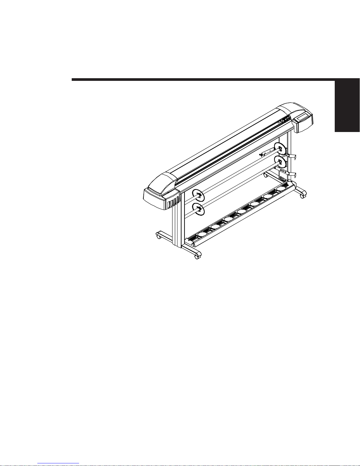
Figure 1-1. Novajet PROe Series Inkjet Printers.
Introduction
This manual provides service information for the ENCAD®, Inc.
Novajet® PROe Series Color Inkjet Printer. There are two versions of the Novajet PROe printer: Novajet PRO 42e
and Novajet PRO 60e.
It is written for service personnel who possess analog and digital
circuitry experience. Chapter 2, Theory of Operation, should be read
and thoroughly understood before troubleshooting/calibrating the
printers.

18 General Description
Novajet PROe Series Service Manual
The printers support pre-cut and roll media. Media size is automatically determined and hardclip limits are set accordingly. Precut media uses different maximum plotting areas than roll media.
See the Printer Specifications for more details.
Both RS-422 serial and Centronics parallel connections are provided
to interface with the host computer. Commands sent from the host
computer can be in several forms including HP-RTL, and Encad
RTL formats.
Drivers are supplied to support Windows-based PC’s (3.XX, 95, and
NT) as well as Macintosh and Power PC computers.
These printers expand upon ENCAD’s tradition of delivering fast,
high-quality color or monochrome graphics for a variety of applications. ENCAD has made significant advances in designing these
printers to respond to and anticipate our customers’ needs. Principal features are summarized below.
Locally or Remotely Configured via Host Computer
Powered Media Take-Up and Feed System
Media Drying System
Quick Ink Changeover
Self-Aligning Pinch Rollers
PowerPC 33 MHz Microprocessor
8 User Configurable Settings
104 Jet Ink Cartridges
Ink Priming System
500ml Ink Reservoirs
Smart Cartridges

General Description 19
GENERAL
DESCRIPTION
Novajet PROe Series Service Manual
Overview
Printers draw according to instructions issued from a “host” computer. Every printer is engineered to understand a specific set of
instructions and to execute each instruction in a precise manner.
In addition, most printers are designed to execute predetermined
characters automatically without a specific line-by-line instruction
from the program. These characters are part of the printer’s
permanent memory.
Related Publications
The following publication contains additional information which may
be useful in servicing the ENCAD, Inc. Novajet PROe Color
Inkjet Printers:
• ENCAD, Inc. Novajet PROe User Guide,
P/N 208713-1
Copies of this and other ENCAD, Inc. publications may be obtained
by contacting your nearest authorized ENCAD, Inc. dealer or by
contacting ENCAD’s Technical Support and Service Department.
Electrostatic Discharge (ESD) Sensitivity
All PCBs (Printed Circuit Boards) associated with the Novajet
PROe printers have components sensitive to ESD (electrostatic
discharge). Care must be taken to avoid damage to any of the
components by following current ESD handling procedures and
practices.
Always use an approved ESD grounding strap when handling or
working with PCBs.

20 General Description
Novajet PROe Series Service Manual
W arnings, Cautions, and Notes
Warnings, cautions, and notes are used when additional information, instructions, or care should be observed. In this manual,
warnings cautions, and notes precede the text to which each applies. The definition of each is provided below.
WARNINGS - Warnings are used to stress that the following steps
or procedure has the potential to cause serious harm or death to
service personnel. Extreme care should be observed when following
the procedures and to exercise standard safety procedures. They
are indicated by:
Followed by a paragraph describing the concern.
CAUTION - Cautions depict that the following steps or procedures
can cause damage to the equipment if not properly followed. Extreme care should be observed when following the procedures and
to exercise standard safety procedures. They are indicated by:
Followed by a paragraph describing the concern.
NOTE - Notes are placed before a procedure to inform the service
personnel of specific details to improve quality, to give reminders of
interrelated parts, and to provide other helpful information. They
are indicated by:
NOTE
Followed by a paragraph describing the concern.

General Description 21
GENERAL
DESCRIPTION
Novajet PROe Series Service Manual
Printer Specifications
The specifications and performance characteristics of the Novajet
PROe Color Inkjet Printers are as follows:
Max Printing Area:
PRO 42e PRO 60e
Norm 40.8” 58.8”
1.04m 1.49m
Extend 41.61” 59.61”
1.06m 1.51m
Language Emulation:
HP-RTL
ENCAD RTL
Buffer:
8 MB installed
upgradeable to 16, 32,
and 64 MB
Power Requirements:
Input Voltage:
90-246 VAC
47-63 Hz
Output Power:
20 W idle
140 W typical
215 W maximum
Baud Rates:
9600, 19200
38400, 115200
Resolution:
Mono 300x300 dpi
Color 300x300 dpi
Accuracy:
0.2% line length (with
ROLL mode off)
Interface:
Centronics parallel
(IEEE 1284)
RS-422 serial
Network Option: via
10BaseT, 10Base2
Print Server
Environment:
Operating:
59° to 95° F
(15° to 35° C)
10% to 70% RH
non-condensing
Storage:
-5° to 140° F
(-21° to 60° C)
5% to 80% RH
non-condensing
Dimensions:
Height 44” (1.12m)
Width 77” (1.96m)
PRO 42e
95” (2.41m)
PRO 60e
Dept h 28” (0.71m)

22 General Description
Novajet PROe Series Service Manual
Contents of this Service Manual
Figures are used in this manual to clarify procedures. They are for
illustrative purposes only and may not necessarily be drawn to
scale.
Material in this manual may be repeated in various chapters so that
each chapter can “stand alone”. This allows information to be
located without having to refer back and forth between chapters.
Figures and tables are easily located and cross-referenced, and are
listed in the front of the manual under List of Illustrations and List
of Tables.
This manual is divided into six chapters as:
Chapter 1 GENERAL DESCRIPTION - Contains a general
description of the ENCAD Novajet PROe printer. This
includes printer specifications, and related materials.
Also included is a description of the use of Warnings,
Cautions and Notes as used in this manual and chapter
contents.
Chapter 2 THEORY OF OPERATION - Functional
descriptions of the overall printer and major assemblies
are contained in this chapter.
Chapter 3 MAINTENANCE - This chapter covers the
scheduled maintenance, cleaning procedures and
alignment/adjustments recommended to perform on the
printers. Diagnostics and a signal flow diagram are also
listed.
Chapter 4 TROUBLESHOOTING - A table containing
problems that could occur and possible causes and
repairs is found in this chapter. This table is not
intended to be a complete listing of troubleshooting
procedures. It will isolate the problem down to the
lowest replacable assembly. If the problem happens to
be the wiring between assemblies, standard
troubleshooting techniques will have to be implemented
to correct the problem.

General Description 23
GENERAL
DESCRIPTION
Novajet PROe Series Service Manual
Chapter 5 ASSEMBLY/DISASSEMBLY - Contains
detailed procedures to remove and replace printer
parts and assemblies.
Chapter 6 PARTS LIST - Contains a complete listing of
all field replacable parts and assemblies for the
Novajet PROe Color Inkjet Printer. Illustrated parts
breakdown drawings are included to help clarify and
identify parts for ordering. Special kits and
adjustment jigs may also be required.
ORIENTATION - Instructions in this manual are based on the
assumption that the service person is facing the front of the
printer. References to top view, back view, and so forth are
consistent with this engineering standard. References to the
X Axis and Y Axis (Paper Axis and Carrier Axis, respectively)
follow the standard of AutoCAD™ absolute coordinates: up and
down for X, left to right for Y.

24 General Description
Novajet PROe Series Service Manual
Technical Support
ENCAD offers full technical support and service for its various
products. If you are unable to find the answer to your question in
either the User’s Guide, Service Manual, or other related publications, check out ENCAD’s Technical Bulletins located on ENCAD’s
bulletin board or the Internet:
ENCAD BBS: (619) 452-2653 or
(619) 452-3768
ENCAD Website: http://www.encad.com
Additional information is available though our Technical Support
and Service Department’s Help Desk.
ENCAD, Inc.
Technical Support & Service Dept.
6059 Cornerstone Court West
San Diego, CA 92121
Help Desk Telephone: (619) 452-4350
Help Desk FAX: (619) 546-0659
International Users contact your local ENCAD service provider.
see details on your ENCAD registration card.

2
THEORY OF
OPERATION
25
Introduction
This chapter explains the mechanical and electrical theory of operation of the ENCAD Novajet PROe Series Color Inkjet printer.
The Novajet PROe is a PowerPC 33MHz microprocessor-based
digital printer that receives plotting instructions from a host computer through either the RS-422 serial interface or the Centronics
parallel interface.
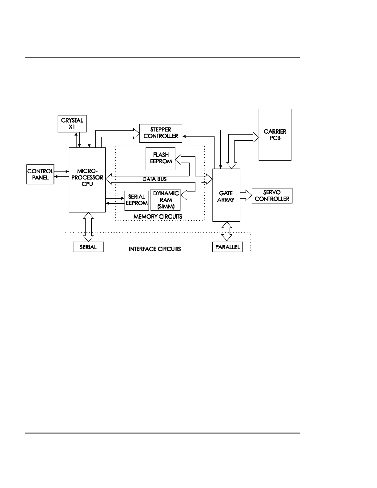
Novajet PROe Printer General Block
Diagram
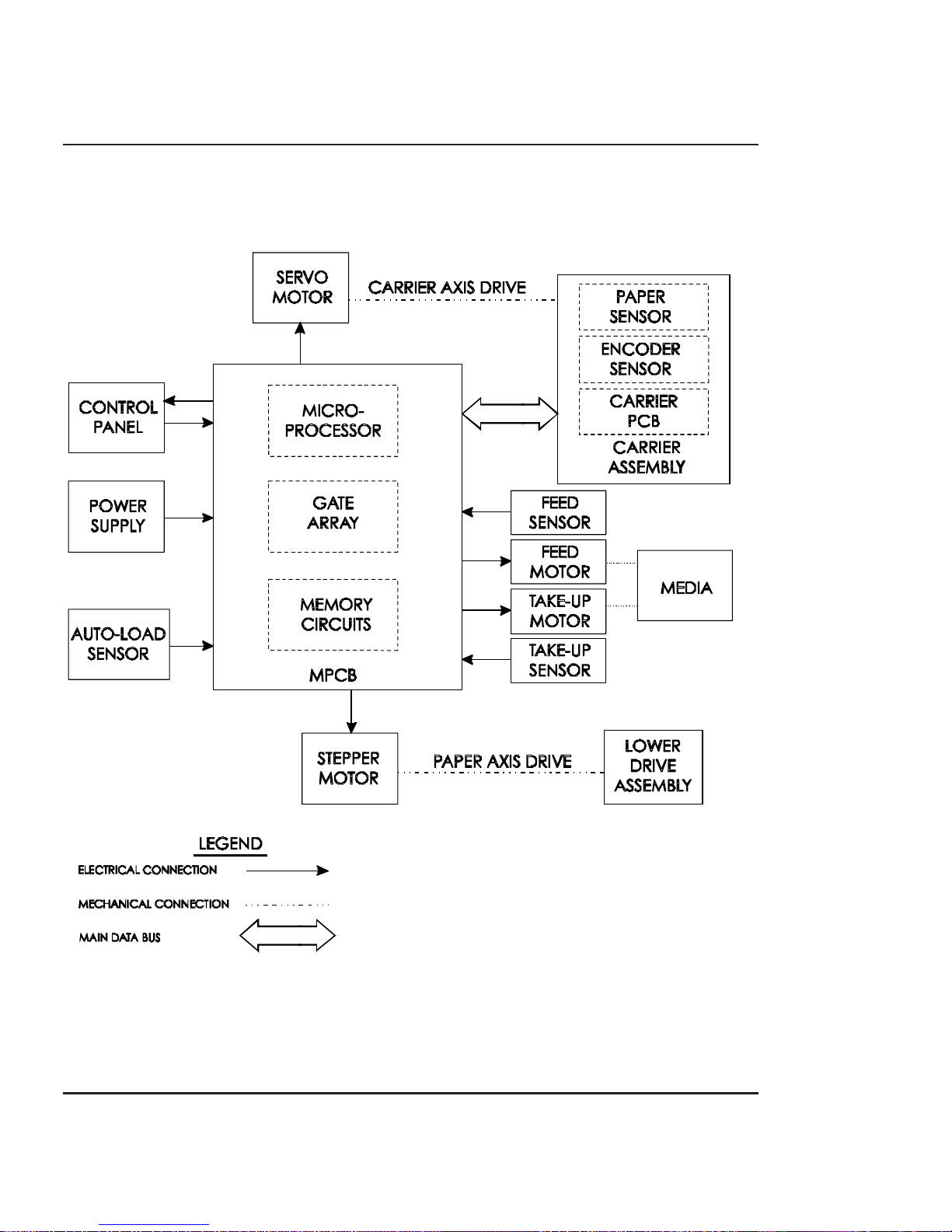
Figure 2-1 illustrates the major functional areas of the printer.
The Novajet PROe printer consists of three mechanical assemblies:
1. Paper (Media) Axis Drive
2. Carrier Axis Drive
3. Media Feed and Take-Up System
and four main electrical assemblies:
1. MPCB (Main Printed Circuit Board)
2. Carrier Assembly
3. Keypad
4. Power Supply
Theory of Operation
26 Theory of Operation
Novajet PROe Series Service Manual
Figure 2-1. General Block Diagram.
Theory of Operation 27
THEORY OF
OPERATION
Novajet PROe Series Service Manual
Paper (Media) Axis Drive
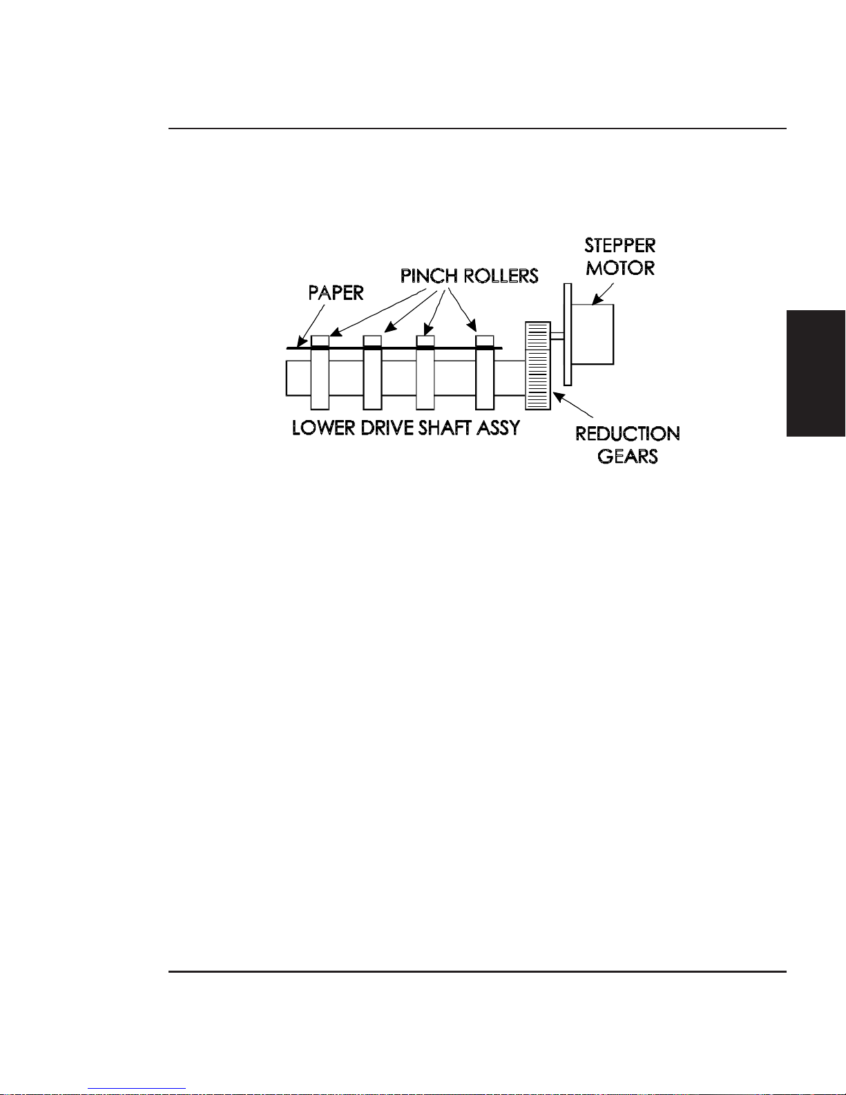
Figure 2-2. Paper (Media) Axis Drive.
The Paper (Media) Axis Drive moves the plotting media in a direction perpendicular to the length of the printer. This friction drive
utilizes a micro-step drive technology and consists of a stepper
motor, reduction gears, lower drive shaft assembly, and pinch
wheels. This can be seen in figure 2-2.
The micro-step technology associated with the stepper motor gives
the capability of a resolution up to 9600 dpi.
The reduction gear meshes the stepper motor to the lower drive
shaft assembly which allows the media to advance or retract. The
purpose of the pinch wheels is to apply pressure to the media onto
the drive shaft assembly to reduce the chance of slipping.
Misaligned pinch wheels is the main cause of skewing of the media.
28 Theory of Operation
Novajet PROe Series Service Manual
The Carrier Axis Drive
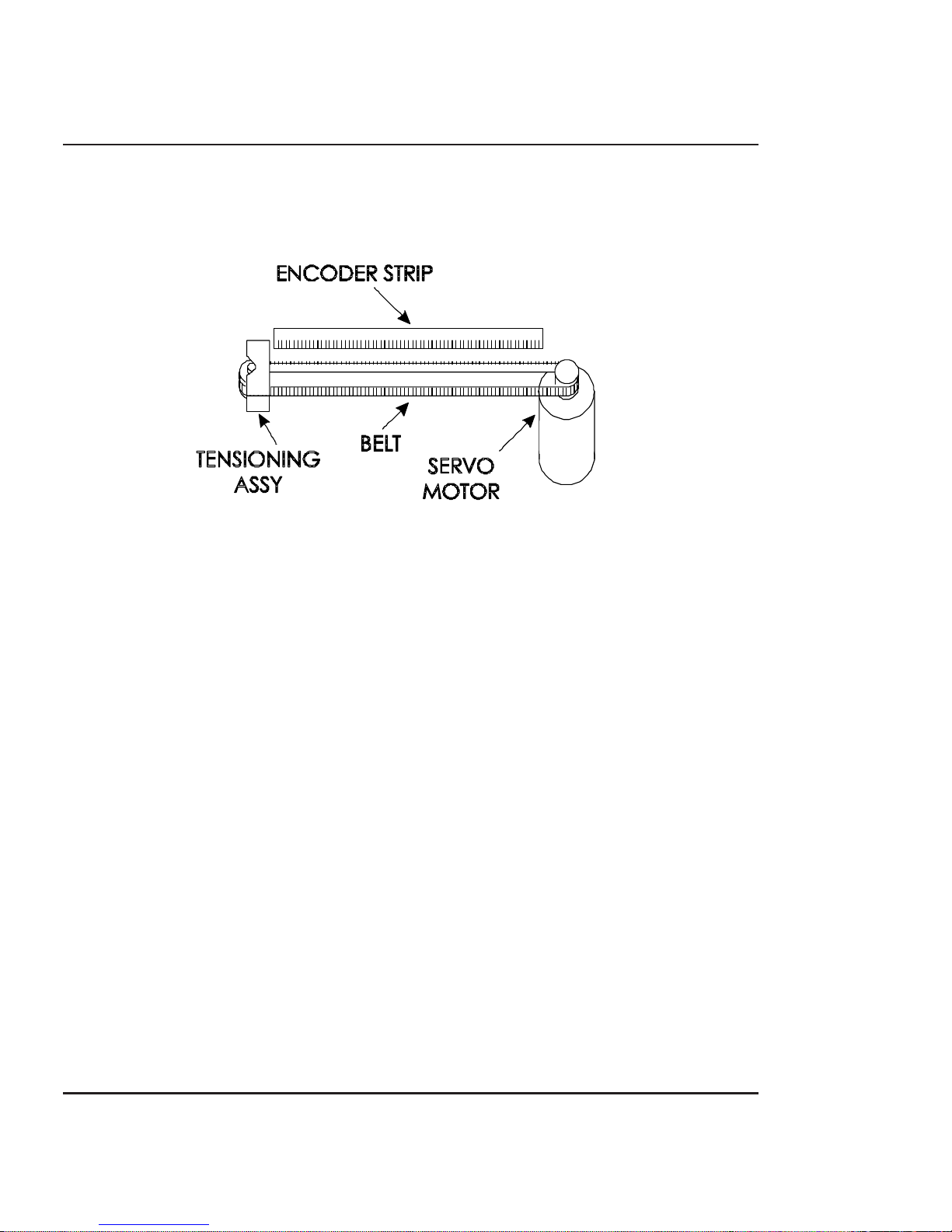
Figure 2-3. Carrier Axis Drive.
The Carrier Axis Drive moves the printer’s carrier assembly along
the length of the printer. The drive consists of a servo motor, linear
encoder strip, drive belt, and tensioning assembly. These items are
illustrated in figure 2-3.
The servo motor, drive belt, and tensioning assembly are the components that actually drive the carrier assembly. The servo motor
drives the belt back and forth allowing the attached carrier assembly
to be repositioned as required. The tensioning assembly is spring
controlled and allows the proper amount of tension on the belt.
The linear optical encoder strip is used to obtain the printers accuracy along the axis of the printer. It is made with 150 parallel lines
per inch etched into it. By utilizing two optical encoder sensors that
are slightly off set from each other, and reading the leading and
trailing edges of the lines, a resolution of 600 dpi can be obtained.
The stepper and servo motors are controlled from the main printed
circuit assembly by the microprocessor.
Theory of Operation 29
THEORY OF
OPERATION
Novajet PROe Series Service Manual
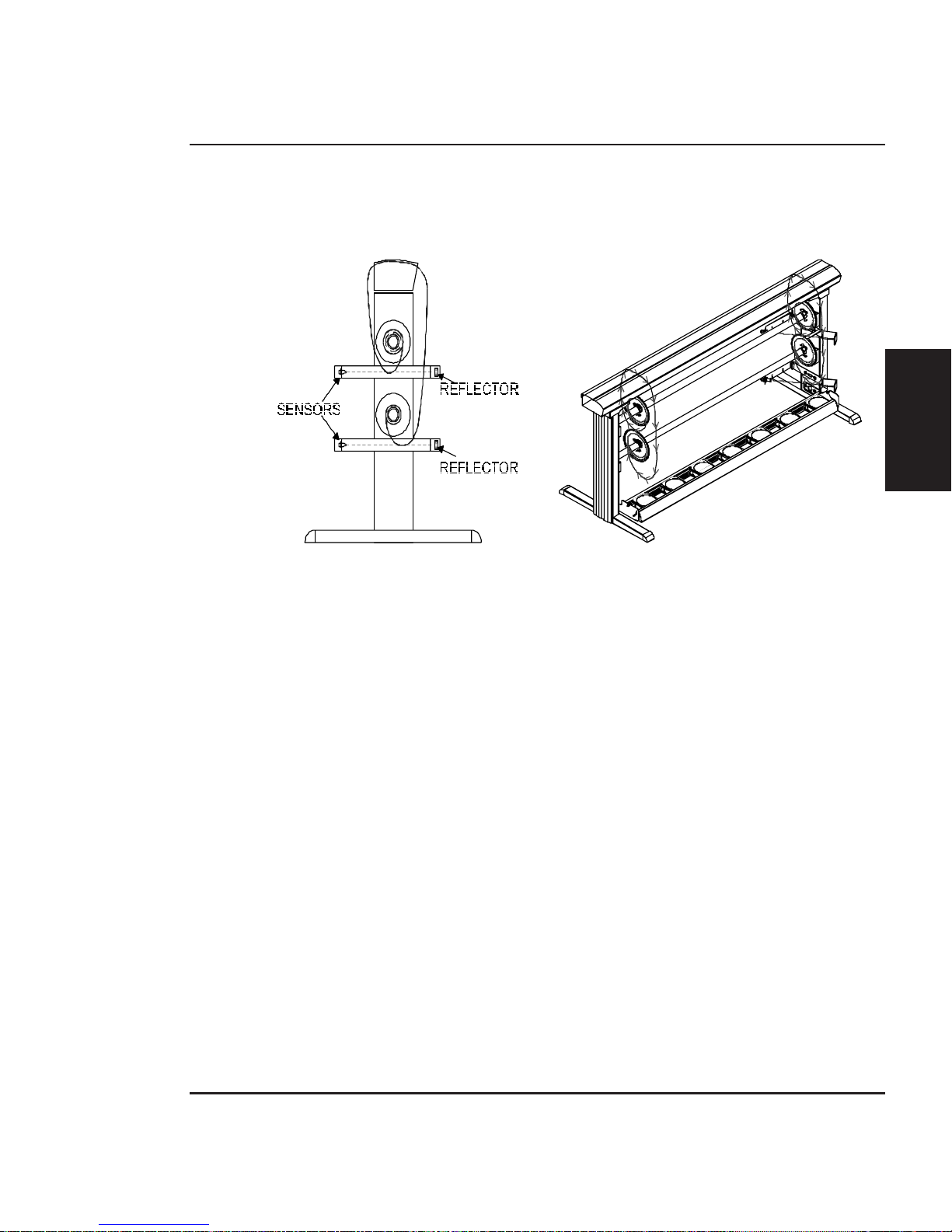
Media Feed and Take-Up System
Figure 2-4. Power Feed and Take-Up System.
The media feed and take-up system comprises of two optical sensors
and two dc motors. See Figure 2-4.
The motors are used to advance the media feed roll and the media
take-up roll dependant upon the signals they receive from the
MPCB. The MPCB generates the control signals for the motors from
the information it receives from the media feed and take-up sensors.
The optical sensors are designed to inform the MPCB when there is
not a proper amount of slack in the media by sensing the ‘curl’ of the
media at the bottom of its loop. This method is used so that all
approved forms of media (including transparent backlit media) is
able to take advantage of the power feed and take-up system.
30 Theory of Operation
Novajet PROe Series Service Manual
Main Printed Circuit Board (MPCB)
Figure 2-5. Main Printed Circuit Board.
The Main Printed Circuit Board (MPCB) consists of six functional
areas:
1. Microprocessor (CPU)
2. Gate Array
3. Memory Circuits
4. Stepper Motor Controller
5. Servo Motor Controller
6. Interface Circuits: Serial & Parallel
 Loading...