


CADJET® 3D
Wide Format Inkjet Printer
User Guide
Text P/N 215319-1 Rev. B
Copyright © ENCAD, Inc. 2000
NOVAJET®, ENCAD®, CADJET®, NovaXsell™, Posterizer™, Extreme Color
Printing™ and Quality Imaging Supplies™ are trademarks of ENCAD, Inc.
Other trademarks are the property of their respective owners.
Except as provided below, no part of this manual may be copied or distributed,
transmitted, transcribed, stored in a retrieval system, or translated in any human
or computing language, in any form or by any means, electronic, mechanical,
magnetic or otherwise, or disclosed to a third party without the express written
permission of ENCAD, Inc., 6059 Cornerstone Court West, San Diego, CA
92121, U.S.A.
Certain manuals are distributed by ENCAD in an electronic format on CD-ROM
or over the internet. The registered user of an ENCAD product whose manuals
is distributed in this fashion may print one copy for their personal use only.
Revision History
Rev. A March 2000
Rev. B April 2000

ii
CADJET® 3D User Guide
WARRANTY CLAIMS
United States
ENCAD®, Inc., warrants its printers (“PRODUCT”) to be free from defects in workmanship and
materials for a period of one year from the date of purchase. In order to submit a Warranty claim,
please contact the ENCAD Help Desk at (858) 452-4350.
ENCAD reserves the right to make changes or improvements to Products, without incurring any
obligation to similarly alter Products previously purchased.
Buyer’s sole and exclusive rights pursuant to this Warranty shall be for the repair or replacement
of defective Product. ENCAD specifically disclaims any and all other warranties, expressed or
implied, including but not limited to, implied warranties of merchantability and fitness for a
particular purpose. In no event shall ENCAD be liable for any loss of profit or other commercial
damages, special, incidental or consequential damages, or any other damages or claims, whatsoever.
This Warranty gives Buyer specific legal rights, and Buyer may also have other rights that vary
from state to state.
This Warranty applies only to printers purchased from ENCAD, or authorized ENCAD distributors or dealers. The intent of this Warranty is to repair or replace defective Products subjected to
normal wear and tear, when operated according to ENCAD instructions.
This warranty does not cover damage to the Product resulting from the following:
· Accident or negligence.
· Unauthorized modification of the Product.
· Adverse environmental conditions.
· Service of the Product by other than an ENCAD authorized service provider.
· Unauthorized or improper use, including but not limited to:
- Use in applications for which the Product was not designed.
- Using cartridges, ink, or media other than ENCAD QIS products.
- Lubricating any part of the printer.
Internationally: Contact your reseller for warranty information.
Extended Warranty: An extended warranty is available for your printer. For information in the
U.S., call 1-800-45ENCAD. Internationally, contact your reseller for further information.

iii
CADJET® 3D User Guide
FCC Statement (U.S.A.)
The United States Federal Communications Commission has specified that the following notice be
brought to the attention of users of the ENCAD printers.
FEDERAL COMMUNICATIONS COMMISSION RADIO AND TELEVISION INTERFERENCE FOR CLASS A DEVICE
Statement
This equipment has been tested and found to comply with the limits for a Class A digital device,
pursuant to Part 15 of the FCC Rules. These limits are designed to provide reasonable protection
against harmful interference in a residential installation. This equipment generates, uses, and can
radiate radio frequency energy, and if not installed and used in accordance with the instructions,
may cause harmful interference to radio communications.
User Instructions:
If the equipment does cause harmful interference to radio or television reception, which can be
determined by turning the equipment on and off, the user is encouraged to try to correct the
interference by one of the following measures:
• Reorient or relocate the receiving antenna.
• Increase the separation between the equipment and receiver.
• Connect the equipment into an outlet on a circuit different from that to which the receiver is
connected.
• Consult the dealer or an experienced radio/TV technician for help.
Changes or modifications not expressly approved by ENCAD, Inc. could void the user’s authority
to operate the equipment.
Note: This product was FCC certified under test conditions that included the use of shielded I/O
cables and connectors between system components. To be in compliance with FCC regulations,
the user must use shielded cables and connectors and install them properly.

iv
CADJET® 3D User Guide
VDE statement
Hiermit wird bescheinigt, daß der Drucker in Übereinstimmung mit den Bestimmungen der
BMPT-AmstbIVfg 234/1991 funkentstört ist. Der vorschriftsmäßige Betrieb mancher Geräte
(z.B. Meßsender) kann allerdings gewissen Einschränkungen unterliegen. Beachten Sie deshalb
die Hinweise in der Bedienungsanleitung.
Dem Zentralamt für Zulassungen im Fernmeldewesen würde den Inverkehrbringen dieses Gerätes
angezeigt und die Berechtigung zur Überprüfung der Serie auf die Einhaltung der Bestimmungen
eingeräumt.
Industry Canada
This Class A digital apparatus meets all requirements of the Canadian Interference-Causing
Equipment Regulations.
Cet apparell numérique de la classe A respecte toutes les exigences du Réglement sur le matériel
brouilleur du Canada.
Material safety data sheet
To obtain information on the proper use, handling, and disposal of any ENCAD QIS ink,
consult the material safety data sheet included in the ink kit or obtain a copy from
ENCAD, Inc. at:
6059 Cornerstone Court West
San Diego, California 92121-3734
(858) 452-4350
International users should contact their local reseller.

v
CADJET® 3D User Guide
General operating safety
The use of a <HAR> cord set (rated 10A, 250VAC) with the proper plug configuration
for the country where the device will be used, is required for continued safety compliance.
Ein harmonisiertes (<HAR>) Netzkabel (min. 10A, 250V~) mit dem vorgeschriebenen
Netzstecker für das entsprechende Land in dem das Gerät installiert wird, ist unbedingt
notwendig für die elektrische Sicherheit.
El uso de cable poder <marcado HAR> (capacidad de 10A, 250V~), con el enchufe
apropiado para el país donde se use el producto, es requerido para acatamiento de
seguridad eléctrica.
L' emploi d' un cordon surmoulé <HAR> (estimé 10A, 250V CA) avec la configuration
de la fiche convenable pour le pays où l' appareil sera utilisé, est exigé pour la
conformité à la sécurité continuée.
Manual conventions
➪ Indicates a procedure for you to follow in order to perform a specific function.
Read the accompanying explanatory text before following the step-by-step
procedure.
! Indicates a warning. Ignoring the warning can damage the printer or result in an
unsatisfactorily printed image.
✓ Indicates a tip or suggestion that can make using the printer easier or improve
your printed images.

vi
CADJET® 3D User Guide
Other reference materials
In addition to this guide, the following additional documentation is included with your
printer:
Quick Start Guide - Tells you how to assemble and install the printer's hardware.
Two CD-ROMs
One CD-ROM contains sample images.
The other CD-ROM contains:
• this guide;
• Maintenance Guide, instructions for maintaining your printer;
• V/R Xpress driver;
• Heidi driver;
• ADI driver; and
• print server software.

vii
CADJET® 3D User Guide
Contents
Introduction ............................................................ 1-1
Printing .....................................................................................1-1
Obtaining quality results .............................................................1-2
Caring for your ink and cartridges ................................................1-3
Nine Factors that Affect Print Quality ...........................................1-4
Printer options ........................................................ 2-1
Returning to the default settings ..................................................2-1
Printing the settings ...................................................................2-1
Choosing print mode options .......................................................2-1
Important notes about image size vs. dpi......................................2-2
Color mode................................................................................2-3
Quality modes ...........................................................................2-3
Choosing feed media options ......................................................2-4
End of media .............................................................................2-4
Media counter............................................................................2-5
Choosing paper options ..............................................................2-6
Supply Type ..............................................................................2-6
Media standard ..........................................................................2-7
Margins ................................................................................... 2-10
Auto-Load Delay ...................................................................... 2-11
Auto-Cut ................................................................................. 2-11
Save Media ............................................................................. 2-11
Auto-Wipe ............................................................................... 2-12
Defining user setup .................................................................. 2-12
Choosing a language ................................................................ 2-13
Choosing ink options ................................................................ 2-13
Printer Default Settings ............................................................. 2-16
Printing ................................................................... 3-1
ENCAD V/R Xpress driver ...........................................................3-1
Heidi driver ................................................................................3-8
ADI driver ................................................................................ 3-12

viii
CADJET® 3D User Guide
HPGL/2.................................................................... 4-1
CAD printing modes ...................................................................4-1
Printing vector data ....................................................................4-1
Accessing HPGL/2 features ........................................................4-2
Palette select ............................................................................4-2
Control ......................................................................................4-3
Rotation ....................................................................................4-4
Reprints ....................................................................................4-4
Nesting .....................................................................................4-5
Nest wait time ...........................................................................4-6
Ink limit .....................................................................................4-7
HPGL/2 Test File .......................................................................4-7
Installing additional memory ..................................A-1
Acceptable SIMM sizes ............................................................. A-1
SIMM installation ...................................................................... A-1
Serial Communications and Cabling.......................B-1
RS-422 cable requirements ........................................................ B-1
Setting serial communications parameters .................................. B-2
Setting the baud rate................................................................. B-2
Setting the parity bit .................................................................. B-2
Menu tree ................................................................ C-1
Main menu at a glance .............................................................. C-1
Main menu ............................................................................... C-2
Feed media menu ..................................................................... C-3
Setup menu at a glance ............................................................. C-4
Setup menu.............................................................................. C-5
Utility menu at a glance............................................................ C-10
Utility menu .............................................................................C-11
Calibration Menu ...................................................................... C-12
Service Menu........................................................................... C-13
Technical information ............................................. D-1
Error messages....................................................... E-1
Error Messages ........................................................................ E-1
Cartridge Errors ........................................................................ E-1

ix
CADJET® 3D User Guide
Troubleshooting ...................................................... F-1
Troubleshooting quick list ........................................................... F-1
Isolating problems ...................................................................... F-1
Printer Health ............................................................................ F-2
Data Transfer ...........................................................................F-12
Application Software.................................................................F-15
Calling for Help ........................................................................F-17
Customer Technical Support .....................................................F-17

Introduction 1
This User Guide provides complete information on the CADJET® 3D printer.
The printer is a wide-format color inkjet printer that gives you professional-quality output
with all the brilliance and gloss of liquid ink. For CAD, engineering, architectural, creative
and business professionals, this printer lets you experience the value of exceptional
graphics quality and cut hours of production time, while giving you the dramatic impact of
high fidelity images.
Printing
Wide format inkjet printers let you create printed pieces the length of a roll of media (up to
300'). Only Extreme Color Printing™ combines the technical sophistication of the
CADJET printer with the unique qualities of ENCAD CIS ink and media.
Your printer features a continuous-feeding ink system which uses 500ml reservoirs for
each color, so you never have to worry about running out of ink halfway through a big
print job. Before starting a print job, just look at the transparent plastic reservoirs to
check the ink supply. When the ink supply is low, just open the cap and refill.

Introduction 1-2
CADJET® 3D User Guide
The printers accept raster-oriented data in the form of HP RTL format. In this mode,
printing begins immediately after the first complete line of HP RTL data is received.
Depending on the software used, millions of colors are possible, yielding superb results.
If your applications do not support HP RTL, there are several software utilities available
to convert various raster file formats (TIFF, GIF, BMP, etc.) into HP RTL. There are also
more than 50 Raster Image Processors (RIPs) which convert Postscript or CGM to HP
RTL. When choosing a RIP or a file format converter for output to the printer, make sure
it has the features you need. (Contact your ENCAD distributor or dealer for an up-to-date
listing.)
Obtaining quality results
You have probably seen a demonstration of your printer's capabilities or sample output. If
so, you are aware of the superb color graphics which can be obtained, and the variety of
papers and films you can use. Note, however, that to obtain high-quality results, you must
consider several factors. Follow the simple guidelines in the sections that follow to obtain
excellent results.
Use the right inks and media
ENCAD’s commitment to Extreme Color encompasses media, ink, and cartridges. A
team of color scientists and media specialists work with world class ink and media
manufacturers to develop supplies that are scientifically matched to ENCAD printers.
Used together, ENCAD inks and media provide the widest color gamut available, making
our Quality Imaging Supplies ideal for applications from proofs to presentations.
ENCAD inks and media give you optimal image quality through:
• Scientifically matched ink and media
• Ultra-wide color gamut or process standard
• Media: bond paper, photogloss, vellum, and clear film.

Introduction 1-3
CADJET® 3D User Guide
Caring for your ink and cartridges
! Handle cartridges only on the plastic areas. Touching the copper electrical interconnect
or the inkjets can damage the cartridge.
• Be sure the ink in the cartridges matches the ink in the reservoirs.
• Do not mix inks.
• Do not shake ink refill containers.
• Store ink and cartridges in the same environment as the printer whenever possible.
• Removing cartridges may result in loss of negative pressure and cause the cartridge to
leak through the jet plate. If you remove a cartridge from the printer, do not leave it
exposed to the air for an extended period because the jets may clog. Replace the
original tape on the jet plate. Place the cartridge in a cartridge garage or sealed plastic
bag and store it in a closed area at room temperature. Keep it out of direct sunlight.
• Open new cartridges only when you are ready to install them.
• Use only ENCAD-brand ink refills and cartridges.
• Drawings containing both black and color elements require alignment of the cartridges
to each other. See the Quick Start Guide for details.
Choose the right media
You can rely on ENCAD media for rich, vivid images across the entire color spectrum.
ENCAD media is specially formulated to demanding specifications, strict performance
criteria, and uncompromising quality controls. This assures superb interaction with CIS Ink
and flawless performance with the printer.
Caring for your media
Store media in its original packaging in a cool, dry area until you are ready to use it. The
environment should be stable; i.e., no extremes of heat and cold, and non-condensing
humidity. If conditions are outside the operating ranges recommended for the printer,
allow the media to acclimate in the operating environment for at least 48 hours before
using it.
If you remove a roll of media from the printer, be sure to store it in a manner which keeps
it clean and dust-free. Ideally, you should return it to its original packaging for storage.

Introduction 1-4
CADJET® 3D User Guide
Print on the correct side! Roll media is wound with the coated side out. Cut sheet
media has an ink-receptive and a non-ink-receptive side. The sheets are notched to help
you orient them correctly. To assure that you print on the correct side, be sure that the
notch is in the upper right corner when you feed the sheet into the printer.
Handle with care! Handle your media carefully to avoid creases, scrapes, and tears.
Avoid crushing or damaging roll media edges.
Wear cotton gloves! Film-based and photographic paper-based media are susceptible to absorbing skin oils. Fingerprints on the media prior to printing may
result in visible fingerprints after ink is applied.
Choose the correct printing mode
There are four pre-defined printing modes, giving you freedom to tradeoff drawing quality
and speed. When printing heavier renderings, maps, or art graphics, choose one of the
enhanced printing modes (Normal or Best).
Use the right software
The quality of the software driver or the RIP can be very important, especially when
printing continuous tone images or 3D renderings. Error diffusion or stochastic screening
algorithms can yield photo-like images, even when these images are scaled to full size.
Software without advanced imaging features may produce images which are grainy when
enlarged.
Nine Factors that Affect Print Quality
Understanding all the factors that contribute to print quality is the only way to ensure
perfect printing each and every time. This section details nine important factors; by
controlling them, you can achieve the very best print quality possible.
1. Use the highest quality type of image possible.
2. Check to make sure the image is in focus and exposed properly.
3. Scan it with the best scanner possible.
4. Scan it at the proper resolution.
5. Color correct and sharpen the image with software.
6. Ensure your color profile accurately reflects the exact ink and media you are using.
7. Use the best diffusion pattern available in your RIP.
8. Use only the best possible ink and media combinations.
9. Make sure your cartridges are aligned and firing properly.

Introduction 1-5
CADJET® 3D User Guide
1. Original Image Type
The type of original image will determine the quality of your final inkjet print. The best
image type is an original transparency (not a duplicate). They are extremely crisp with
superb edge definition. Print film photos are not as good as they are already one generation removed from the original film. Also, because of the emulsion process of photo
prints, edge definitions tend to be lost. Color prints can be used, but they have to be of
very good quality to produce acceptable scaled prints. Digital photo files are newest
image type. Many are unacceptable for large-format printing as they contain only a
small fraction of the information contained in a film transparency.
For example, most digital cameras can only create a 1 MB file. This is not enough
information for large inkjet prints. A file must be at least 10 - 12 MB for a fair print and
30 - 50 MB for a good E-size print (see scanning section). Only the best commercial
digital cameras can achieve these files sizes. Digital files from other sources such as
CD stock photography are usually created from scanned transparencies, so may be
suitable for inkjet printing. Check with the manufacturer to ensure that the images are at
least 10 - 12 MB and were created from drum-scanned transparencies.
The better CDs have images of 28MB or more stored in a TIFF format. These are
preferable for great quality prints. If you use a file stored in PhotoCD format, make sure
you use the highest resolution available. Images stored in compressed files such as
JPEG, LZW, GIF, etc. can lose valuable data during the compression process. Avoid
images stored this way if possible. If you have to use a compression file format for
whatever reason, use JPEG. It is closer to a “lossless” compression.
2. Original Image Clarity and Color
The quality of the original photograph, transparency, or digital file plays a key role in
final print quality as this is where the clarity and color of the image is created. If the
original photographer took a picture that was not in focus, or was fuzzy for any reason,
sharpening or after-effects cannot correct it and a poor inkjet print will result. Differences in film, speed, grain, or developing process can also affect quality of prints. If the
image was too dark or too light, color correction cannot correct it and a poor inkjet print
will result. The axiom of “garbage in, garbage out” applies to all printing, including
inkjet printing. Companies that utilize a lot of photography for large-format inkjet
printing should check for focus by using a loupe. If you have a good, in-focus original,
you can maintain the image quality throughout the entire process.

Introduction 1-6
CADJET® 3D User Guide
3. Scanner Type
How you get the original image into the computer is important to the overall printing
process as scanner quality varies greatly. Using a scanner that meets the requirement of
the overall print quality is essential to have enough color fidelity and edge clarity. An
image scanned with a low end scanner will lose detail, clarity, and color. It is important
that you understand what type of image quality is required for your print and use the right
scanner to achieve it.
Traditionally, drum scanners are ideal for retaining the best edge definition and color
depth. If the original image is poor, an expensive drum scan may be a waste of money.
Almost all service bureaus use drum scanners.
Flatbed scanners require an optional transparency adapter to scan transparencies.
4. Scan Resolution
Scanning the original at low resolution will degrade the large-format inkjet print quality.
Scanning at resolution which is too high slows down the RIP and adds no quality to the
image. Consequently, choosing the right resolution for the output print size (and thus, the
amount of scaling needed after scanning) will determine what the optimum resolution is
for each image.
The quality of the image you would like to produce is determined by the final output size
and the file size. For example, if you want output a 36" x 36" image, the file size will be
approximately 24MB for a fair-good quality image (75dpi), 43MB for a good-very good
quality (100 dpi) and 97MB for an excellent quality (150 dpi) print.
Your service bureau can help you determine the optimum resolution to scan your image
based on the size and quality of the image you would like to print.
DO NOT USE INTERPOLATED RESOLUTION OF YOUR SCANNER TO COMPUTE IMAGE SIZE
Most 300 dpi scanners can interpolate or “imitate” 600 dpi scanning. This is really not
really scanning at 600 dpi and will degrade the image quality. When scanning, ensure that
you are using the scanner's true optical resolution, not its interpolated resolution. Scanning at the highest optical resolution (300 dpi) is better than scanning at the scanner's
highest interpolated resolution (600 dpi).

Introduction 1-7
CADJET® 3D User Guide
5. Post Scanning Color Correction and Sharpening
All scanned images, even those scanned on expensive drum scanners, must be color
corrected and sharpened before using them for a large-format inkjet print. If you are
using a service bureau for scanning images, their scanner operator will usually do this as
part of the scanning fee. However, you should always check the image before using it.
Although the process of color correction and sharpening are more detailed than can be
explained within this document, the following outline will give you a good grasp of
what is required:
Color Correction - all scanners give the image a slight color cast during the scanning
process. This happens because all light sensing devices have a slight bias. The easiest
way to correct most of this color cast is to use a function such as Auto Levels in
PhotoShop. This function finds the whitest pixel and the darkest pixel in an image and
distributes all colors in-between. This works well on 75% of all images that are properly
exposed. In very dark night scenes or in very white snow background scenes, Auto
Levels does not work properly and the correction must be made manually using histogram adjustments.
Sharpening using UnSharp Mask - all scanned images, even images scanned on the
most expensive drum scanners, need to be sharpened. The best digital tool to do this
with is a function called an unsharp mask (available in programs such as PhotoShop).
An unsharp mask basically redefines the edges of images by adding a mask. Most
unsharp mask tools allow you to set the pixel width of the mask and the amount of
sharpening. A good start is to use a pixel width of 3 - 5, with an amount of 75%. Too
much unsharp mask will give the whole image a hard, pixelated look. A little more
unsharp mask can be used with inkjet images as they are somewhat diffused in the
printing process, hiding any small amounts of oversharpening.
6. RIP Color Profile
The engine that converts your image into a series of C, M, Y, K dots is called the Raster
Image Processor or RIP. Before it can actually create these dot patterns, it must first
adjust for the colors of the inks, color of the media, dot volume of the cartridges on a
particular machine, and the humidity/temperature of the environment on the day of
printing (as this affects how far the ink will spread or dot gain). Most RIPs include what
is commonly referred to as a color profile or color link. This profile is automatically used
when you choose the media and ink within the software.

Introduction 1-8
CADJET® 3D User Guide
7. RIP Diffusion/Dither Patterns
Images that are going to be printed on an inkjet printer are eventually divided into C, M, Y,
K and rasterized into dots using patterns that cause the eye to see a continuous tone
image. These patterns are called many things, such as frequency modulated screening,
diffusion patterns, dither patterns, screen patterns, etc. There are various types of screening that are better for photographic images. Stochastic screening was developed specifically for the CMYK process to avoid the problem of visually perceptible banding that
occurs with other pattern types. It does this by pseudo-random placement of dots. Variations of the stochastic strategy have evolved into even better patterns. Each RIP manufacturer uses different names to describe its particular variation on the stochastic theme. To
get the best print quality, make sure you are using the best possible diffusion pattern
available from the RIP software you are using. Also remember that a different diffusion
pattern should be used for spot color objects (such as filled vector objects). If you are
printing an image that contains both photographs and spot color objects, use the diffusion
pattern designed for photos.
8. Ink and Media
Using the right ink and media is a much bigger factor in print quality than most inkjet
users realize. It takes many months of using a printer before a user begins to understand
what an exceptional print looks like. Then and only then can they fully appreciate what
quality materials and inks can do. Inks must be developed specifically for a particular
head, otherwise, cartridge reliability will be severely reduced. ENCAD inks are specifically developed for ENCAD cartridges, printers, and media. These inks create the perfect
ink drop shape, trajectory, and landing shape when used with ENCAD cartridges. The
media controls the color, dot gain, and durability of the final print. As the ink must
chemically interact with the media, only medias developed specifically for a particular
ink can achieve the perfect dot shape that leads to improved image quality. Additionally,
the chemical bond created through co-developed inks and medias is much better than
independently developed inks and medias. Although many people will not be able to
visually perceive differences in quality inks and medias initially (poor inks and medias
show more pronounced visual defects), a less-than-optimal image quality, image color, or
image durability will likely develop over time. Chemical compatibility between inks
(made for a specific head technology) and medias is a key, and often overlooked ingredient to print quality.

Introduction 1-9
CADJET® 3D User Guide
9. Cartridge Preparation and Alignment
The single most overlooked factor in image color accuracy and quality is cartridge alignment. Even if you carefully control factors 1 though 8, a printer with poor cartridge
alignment or unmaintained heads can severely deteriorate image quality. Cartridge
maintenance and alignment are key to producing images that exhibit the best of what a
printer is capable of. Printer wiping stations must be kept clean so that heads stay clean.
Cartridges need to be aligned and checked to be sure that all nozzles are working properly. Use a loupe to evaluate the registration of test patterns to achieve the best possible
accuracy. Whenever you adjust, move, or replace a cartridge, take the time to realign the
cartridges. Alignment errors of a single pixel (or single digit in the alignment process)
will affect both color and image quality.

Printer options 2
You can define printer options through your application software or by choosing settings
from the printer's control panel. The following printer options are described in this
chapter:
• Initialize (return to printer default settings)
• Print Mode
• Paper Options
• User Setup
Returning to the default settings
Pressing the Setup/User Setup/Init Settings buttons returns all printer options to the
factory defaults. All saved user settings are lost. The table at the end of this chapter
shows the printer defaults.
Printing the settings
Pressing the Setup/User Setup/Print Settings buttons causes the printer to print a
listing of its current settings. Be sure to have paper loaded before you start.
Choosing print mode options
Your printer offers several print modes which let you make tradeoffs between speed and
quality.
The print mode you use depends on various factors, such as your software application,
whether you’re printing in color or monochrome, and the type of media you’re using.
Each print mode directly affects the printing speed and quality of the image you print, so
you should understand the differences.
Each of the print modes attempts to strike a balance between speed and quality, with the
quality mode providing quality images at a reasonable printing speed for most users.
Whenever you choose a print mode other than Normal, you will choose to emphasize
either speed or quality.
Print mode options include color mode and print quality.
Default print mode settings are summarized in the table which follows.
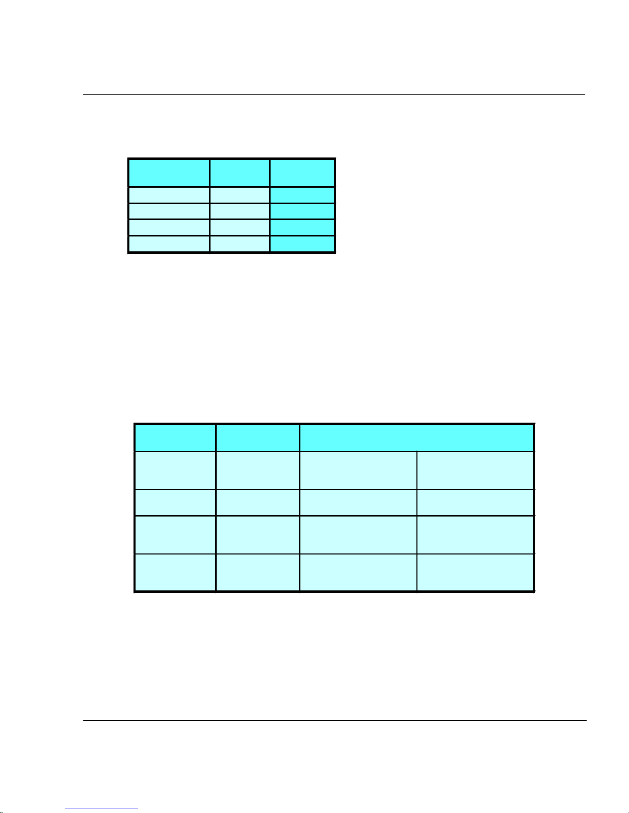
MODE DPI # OF
PASSES
DRAFT 600X600 1
SUPER DRAFT 600X300 1
NORMAL 600X600 3
BEST 600X600 4
Important notes about image size vs. dpi
For best results, be sure the printer dpi setting matches the image resolution in the
file you are printing.
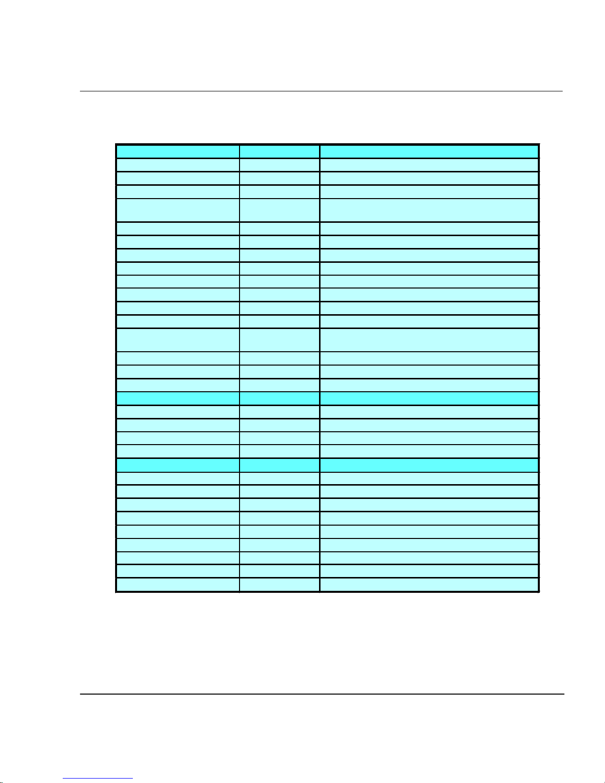
CADJET® 3D User Guide
The printer always prints at 600 dpi, even when the dpi setting in the Print Mode
menu is set to 300 dpi. The dpi setting refers to the resolution at which your image is
created, not the resolution at which it is printed.
Image (file)
resolution
300 dpi 300 dpi 1 input pixel prints as 4
300 dpi 600 dpi 1 input pixel prints as 1
600 dpi 300 dpi 1 input pixel prints as 1
600 dpi 600 dpi 1 input pixel prints as 1
Printer dpi
setting
output pixels.
output pixel.
output pixel.
output pixel.
Effect on printed output
The printed image is the
same size as the
original.
The printed image is 1/4
the size of the original.
The printed image is four
times the size of the
original.
The printed image is the
same size as the
original.
Printer Options 2-2

Color mode
Color mode refers to whether you are printing in color, grayscale or monochrome.
CADJET® 3D User Guide
➪
To choose the color mode
1 Press Setup/Print Mode/Color Mode.
2 Choose Color, Mono, or Gray.
3 Press OK.
Quality modes
There are four print quality modes. Draft and Super Draft modes are suited for line
drawings and drawings with light solid fills, the types of images created by most CAD
users. These modes are not recommended for printing images, because bleeding may
occur in areas of heavy fills or dark shading when printed with these modes.
Draft - This mode generally is used when speed is more important than quality. Use it to
check position, layout, color, etc. It will rarely be used for finished quality images. This
is a single pass mode.
Super Draft - This mode is twice as fast as draft, but trades resolution for speed. It will
rarely be used for finished quality images. This is a single pass mode.
Normal - This setting is useful for fast, better than average quality printing on paper
media. This is a three pass mode.
➪
Best - For images that have sections of high quality continuous tone where quality is
more important than printing speed. This is a four pass mode.
To choose print quality
1 Press Setup/Print Mode/Quality Mode.
2 Choose the desired quality.
3 Press OK.
Printer Options 2-3

Choosing feed media options
Feed media options allow you to:
• define End of Media
• display/enter Media Counter values
Note: Media feeding and loading are described in the Quick Start Guide.
End of media
There are circumstances where the media does not fully advance through the printer. In
this case, the carriage board sensor continues to detect the presence of media and the
printer continues to print. This creates a mess as the printer continues to lay down ink
on the same portion of media.
If the End of Media feature is set to FEEDER STOP, the printer will look for an abnormally long absence of the loop of media that occurs between the feeder roll and the
platen. After 20 seconds, the printer enters pause mode just as if the you had pressed
PAUSE from the main menu. The printer will remain in pause mode until you press
PAUSE (which toggles to the resume state) or you press RESET. Pressing PAUSE
allows you to continue the current print at your discretion.
CADJET® 3D User Guide
A few rules regarding the End of Media feature:
• will not work with Cut Sheet selected as supply type.
• setting is remembered across power cycles.
• setting is not stored as a user parameter.
• setting cannot be changed once a plot begins to print.
• if you press PAUSE to resume the print, detection is disabled for the remainder of
the print.
• if enabled, detection is reinstated at the beginning of each print.
• when the printer is in pause mode due to End of Media, the printer will beep 3
times every 20 seconds until the PAUSE or RESET buttons are pressed.
Printer Options 2-4

CADJET® 3D User Guide
➪
Media counter
To set end of media feeder stop
1 Press Feed Media/End of Media.
2 Choose Feeder Stop.
3 Press OK.
Media Counter gives you a means of estimating the amount of media left on a roll.
When a new roll of media, or a used roll where the remaining length is known, is installed on the printer, you can enter the length of the roll into the printer's front panel
display. As the printer prints, this amount is decremented. You can view the estimated
amount of media remaining on the printer's front panel display. When you are ready to
remove the roll, you can print the estimated amount of media remaining on the roll.
When you reload this media, you can use this figure to enter into the printer's front panel
display. The media counter can be reset to 0 to avoid confusion if the media counter is
not being used. The media counter will not decrement below 0. The current value of the
media counter is maintained across power cycles. The current value is not stored as a
user parameter.
➪
➪
➪
To enter a media length value
1 Press Feed Media/Media Counter.
2 Set the media length.
3 Press OK.
To display the current value
1 Press Feed Media/Display Counter.
2 View the current value.
3 Press EXIT.
To print the current value
1 Press Feed Media/Display Counter.
2 Press Print Counter.
3 Press EXIT.
Printer Options 2-5

CADJET® 3D User Guide
➪
To reset the media counter
1 Press Feed Media/Media Counter.
2 Press Reset Counter.
3 Press OK.
Choosing paper options
Paper options let you define the following:
• Supply Type • Media Standard
• Margins • Auto-Load Delay
• Auto-Cut • Save Media
• Auto-Wipe
Note: Media feeding and loading are described in the Quick Start Guide.
Supply Type
This setting allows you to select your supply options. The available options are sheet
and roll. Select sheet if you intend to use cut sheet stock. Select roll if you are going to
use roll paper.
➪
To choose supply type
1 Press Setup/Paper Option/Supply Type.
2 Choose the supply type.
3 Press OK.
Printer Options 2-6

Media standard
When you create an image, you determine its size at the computer. It's important that you
know the size of the image and load the appropriate size media because the printer
automatically defines the print area based on the loaded media's width. Be sure that the
media you load is wide enough to accommodate the image. If extra length is required,
use roll media. If the media is smaller than the image, the image may be truncated.
Minimum media width is 11".
CADJET® 3D User Guide
➪
To choose the media standard
1 Press Setup/Paper Option/Media Standard.
2 Choose the size of media you are loading.
3 Press OK.
The tables which follow provide details on the media sizes and maximum printing areas
for roll and sheet media.
Printer Options 2-7

CADJET® 3D User Guide
Media Sizes and Maximum Printing Areas for Roll Media
Paper Size Normal Print Area Expanded Print Area
GRAPHICS (U.S. OFFSET)
19.0" x 25.0" 17.8" x 23.8" 18.6" x 24.6"
20.0" x 28.0" 18.8" x 26.8" 19.6" x 27.6"
22.0" x 26.0" 20.8" x 24.8" 21.6" x 25.6"
23.0" x 35.0" 21.8' x 33.8" 22.6" x 34.6"
24.0" x 29.0" 22.8" x 27.8" 23.6" x 28.6"
25.0" x 38.0" 23.8" x 36.8" 24.6" x 37.6"
26.0' x 38.0 24.8" x 35.8" 25.6" x 37.6"
27.0" x 39.0 25.8" x 37.8" 26.6" x 38.6"
30.0" x 42.0" 28.8" x 40.8" 29.6" x 41.6"
32.0" x 44.0" 30.8" x 42.8" 31.6" x 43.6"
35.0" x 45.0" 33.8" x 43.8" 34.6" x 44.6"
36.0" x 45.0" 34.8" x 43.8" 35.6" x 44.6"
40.0" x 50.0" 38.8" x 48.8" 39.6" x 49.6"
42.0" x 65.0" 40.8" x 63.8" 41.6 x 64.6"
48.0" x 65.0" 46.8" x 63.8" 47.6" x 64.6"
50.0" x 65.0" 48.8" x 63.8" 49.6" x 64.6"
54.0" x 65.0" 52.8" x 63.8" 53.6" x 64.6"
60.0" x 65.0" 58.8" x 63.8" 59.6" x 64.6"
U.S. ARCHITECTURAL
A 9.0" x 12.0" 7.8" x 10.8" 8.6" x 11.6"
B 12.0" x 18.0" 10.8" x 16.8" 11.6" x 17.6"
C 18.0" x 24.0" 16.8" x 22.8" 17.6" x 23.6"
D 24.0" x 36.0" 22.8" x 34.8" 23.6" x 35.6"
E 36.0" x 48.0" 34.8" x 46.8" 35.6" x 47.6"
U.S. ENGINEERING
B 11.0" x 17.0" 9.8" x 15.8" 11.6" x 16.6"
C 17.0" x 22.0" 15.8" x 20.8" 16.6" x 21.6"
D 22.0" x 34.0" 20.8" x 32.8" 21.6" x 33.6"
E 34.0" x 44.0" 32.8" x 42.8" 33.6" x 43.6"
ISO-A
A3 297 x 420 mm 267 x 390 mm 287 x 410 mm
A2 420 x 594 mm 390 x 564 mm 410 x 584 mm
A1 594 x 840 mm 564 x 811 mm 584 x 831 mm
625 x 880 mm 595 x 850 mm 615 x 870 mm
A0 841 x 1189 mm 811 x 1159 mm 831 x 1179 mm
METRIC-DIN
A3 337 x 460 mm 307 x 430 mm 327 x 450 mm
A2 460 x 634 mm 430 x 604 mm 450 x 624 mm
610 x 860 mm 580 x 830 mm 600 x 850 mm
A1 634 x 881 mm 604 x 851 mm 624 x 871 mm
860 x 1220 mm 830 x 1190 mm 850 x 1200 mm
A0 881 x 1129 mm 851 x 1199 mm 871 x 1219 mm
1000 x 1414 mm 970 x 1384 mm 990 x 1404 mm
1189 x 1682 mm 1159 x 1652 mm 1179 x 1672 mm
ISO-B
B4 250 x 353 mm 220 x 323 mm 240 x 343 mm
B3 353 x 500 mm 323 x 470 mm 343 x 490 mm
B2 500 x 707 mm 470 x 677 mm 490 x 697 mm
B1 707 x 1000 mm 677 x 970 mm 697 x 990 mm
Printer Options 2-8

CADJET® 3D User Guide
Media Sizes and Maximum Printing Areas for Sheet Media
Paper Size Normal Print Area Expanded Print Area
GRAPHICS (U.S. OFFSET)
19.0" x 25.0" 17.8" x 22.4" 18.6" x 22.8"
20.0" x 28.0" 18.8" x 25.4" 19.6" x 25.8"
22.0" x 26.0" 20.8" x 23.4" 21.6" x 23.8"
23.0" x 35.0" 21.8" x 32.4" 22.6" x 32.8"
24.0" x 29.0" 22.8" x 26.4" 23.6" x 26.8"
25.0" x 38.0" 23.8" x 35.4" 24.6" x 35.8"
26.0" x 38.0" 24.8" x 35.4" 25.6" x 35.8"
27.0" x 39.0" 25.8" x 36.4" 26.6" x 36.8"
30.0" x 42.0" 28.8" x 49.4" 29.6" x 39.8"
32.0" x 44.0" 30.8" x 41.4" 31.6" x 41.8"
35.0" x 45.0" 33.8" x 42.4" 34.6" x 42.8"
36.0" x 45.0" 34.8" x 42.4" 35.6" x 42.8"
40.0" x 50.0" 38.8" x 47.4" 39.6" x 47.8"
42.0" x 65.0" 40.8" x 62.4" 41.6 x 62.8"
48.0" x 65.0" 46.8" x 62.4" 47.6" x 62.8"
50.0" x 65.0" 48.8" x 62.4" 49.6" x 62.8"
54.0" x 65.0" 52.8" x 62.4" 53.6" x 62.8"
60.0" x 65.0" 58.8" x 62.4" 59.6" x 62.8"
U.S. ARCHITECTURAL
A 9.0" x 12.0" 7.8" x 9.4" 8.6" x 9.8"
B 12.0" x 18.0" 10.8" x 15.4" 11.6" x 15.8"
C 18.0" x 24.0" 16.8" x 21.4" 17.6" x 21.8"
D 24.0" x 36.0" 22.8" x 33.4" 23.6" x 33.8"
E 36.0" x 48.0" 34.8" x 44.0" 35.6" x 44.4"
U.S. ENGINEERING
A 8.5" x 11.0" 7.3" x 8.4" 8.1" x 8.8"
B 11.0" x 17.0" 9.8" x 14.4" 10.6" x 14.8"
C 17.0" x 22.0" 15.8" x 19.4" 16.6" x 19.8"
D 22.0" x 34.0" 20.8" x 31.4" 21.6" x 31.8"
E 34.0" x 44.0" 32.8" x 40.0" 33.6" x 40.4"
ISO-A
A4 210 x 297 mm 180 x 232 mm 200 x 242 mm
A3 297 x 420 mm 267 x 355 mm 287 x 365 mm
A2 420 x 594 mm 390 x 529 mm 410 x 539 mm
A1 594 x 840 mm 564 x 775 mm 584 x 785 mm
625 x 880 mm 595 x 815 mm 615 x 825 mm
A0 841 x 1189 mm 811 x 1124 mm 831 x 1134 mm
METRIC-DIN
A4 250 x 337 mm 220 x 272 mm 240 x 282 mm
A3 337 x 460 mm 307 x 395 mm 327 x 405 mm
A2 460 x 634 mm 430 x 567 mm 450 x 579 mm
610 x 860 mm 580 x 795 mm 600 x 805 mm
A1 634 x 881 mm 804 x 816 mm 624 x 826 mm
860 x 1220 mm 830 x 1155 mm 850 x 1165 mm
A0 881 x 1229 mm 851 x 1164 mm 871 x 1174 mm
1000 x 1414 mm 970 x 1349 mm 990 x 1359 mm
1189 x 1682 mm 1158 x 1617 mm 1179 x 1627 mm
ISO-B
B4 250 x 353 mm 220 x 288 mm 240 x 298 mm
B3 353 x 500 mm 323 x 435 mm 343 x 445 mm
B2 500 x 707 mm 470 x 642 mm 490 x 652 mm
B1 707 x 1000 mm 677 x 935 mm 697 x 945 mm
Printer Options 2-9

Margins
Margins can be set to Normal or Expanded. The Expanded setting expands the print
area and decreases the margins.
Any part of the image that extends into the margin will be clipped. When the Margins
option is set to Expanded, make sure that you align the media accurately using the
guide on the right of the platen so that the ink doesn’t exceed the edge of the media.
Cut sheet maximum printing area
Normal: 0.59" (15 mm) margin on each of three sides and 1.38"
(35 mm) margin on the fourth side.
Expanded: 0.197" (5 mm) margin on each of three sides and a 1.38"
(35 mm) margin on the fourth side.
CADJET® 3D User Guide
Rollfeed maximum printing area
Normal: 0.59" (15 mm) margin on all sides.
Expanded: 0.197" (5 mm) margin on all sides.
Printer Options 2-10

CADJET® 3D User Guide
➪
Auto-Load Delay
➪
Auto-Cut
To set margins
1 Press Setup/Paper Option/Margins.
2 Choose Normal or Expanded.
3 Press OK.
Auto-Load Delay lets you set the time between when the printer senses the media and
when printing starts. This lets you manually reposition the media if necessary. The
default is 6 seconds, selectable from a range of 1-12 seconds.
To set auto-load delay
1 Press Setup/Paper Option/Auto-Load Delay.
2 Choose the delay time.
3 Press OK.
When the Auto-Cut option is set to on, the printer automatically cuts the media when the
image is complete. Be sure the image is dry before cutting, turn on the dryer and/or
specify a Dry Time. See “Setting a Dry Time” in this chapter for the procedure. You can
select Cut from the control panel at any time to cut the media.
➪
Save Media
To set auto-cut
1 Press Setup/Paper Option/Auto-Cut.
2 Choose On or Off.
3 Press OK.
When the Save Media is On (the default), the media advances only as far as needed to
print the image. With the Save Media option turned off, the printer advances the full
print area of the loaded media. For example, if a 36 inch roll is loaded, the printer
advances the length of the print area for a standard 36 x 48" sheet even if the printed
image is only 30 inches long.
Printer Options 2-11

CADJET® 3D User Guide
➪
Auto-Wipe
➪
Defining user setup
To turn off Save Media
1 Press Setup/Paper Option/Save Media.
2 Choose Off.
3 Press OK.
The cartridge jet plates are periodically wiped during printing. The default for this function is OFF.
To turn on the wiper
1 Press Setup/Paper Option/Auto-Wipe.
2 Choose On.
3 Press OK.
You can save the options you use most frequently so you don’t have to reconfigure the
printer each time you print an image. You can define up to eight different combinations
of options and save them with a user number ranging from 1-8. Select the user number
you want to use before sending an image to the printer. If your printer driver has hostcontrolled settings, the user setup may be overridden. If possible, disable the driver
control settings.
You can save settings for the following options:
• Cut On or Off • Auto-Wipe On or Off • Save Media On or Off
• Media Standard • Color Mode • Normal or Expanded Margins
• Drying Time • Parity
• Baud Rate • Quality Mode
Printer Options 2-12

CADJET® 3D User Guide
➪
➪
Choosing a language
➪
To save user setup
1 Press Setup/User Setup/Save User.
2 Scroll to the number for the user settings.
3 Press OK.
To use a previously saved user setting
1 Press Setup/User Setup/Select User.
2 Scroll to the number for the user settings (i.e., user 1, user 2, etc.) to use.
3 Press OK.
Printer menus and options can be displayed in the following languages: English, German,
French, Italian, Portuguese, Spanish, simplified and traditional Chinese, Japanese, and
Korean.
To choose a language
1 Press Setup/User Setup/Language.
2 Choose the language to display.
3 Press OK.
Choosing ink options
Ink reduction
Ink reduction lets you reduce the percentage of ink laid down by the printer. This feature
applies only to HPGL/2 format images (vector-based images) and has no effect on
continuous tone images. It is especially useful for images with large amounts of printed
area and helps to avoid bleeding or oversaturating the media. It does, however, change
the appearance of colors, so you may want to run a small test print.
➪
To set ink reduction
1 Press Setup/Ink Option/Ink Reduction.
2 Choose a reduction percentage - 12.5, 25%, 37.5, or 50%.
3 Press OK.
Printer Options 2-13

Ink Preheat
Cartridge heat settings are optimized for ENCAD media being printed in a standard
office environment. If you are experiencing banding, poor fills, or over dot gain, and you
have tried all other means to correct these conditions, you may want to experiment with
the ink preheat settings. These will vary depending on the ambient temperature where the
printer is located and the media and ink used.
Defaults for the heater setting are determined by the ink type in use. The printer determines this by reading the chip on the back of each cartridge. When you adjust the ink
settings, you are increasing or decreasing the heat from the default temperature. Pressing the + (plus) button increases the temperature, pressing - (minus) decreases it. When
you have reached the limits of the temperature range, the panel will display either MAX
or OFF. These settings are saved in the printer. If you change to a different type of ink,
you may need to change the heater settings to accommodate the new ink type.
If you are working in a cold or dry environment, try turning the heat up for a larger dot
size. If the heat is turned up too far, the ink may run or sputter. If you are working in a
humid or hot environment, turn the heat down for a smaller dot size.
CADJET® 3D User Guide
➪
Dry time
➪
To set the ink preheat time
1 Press Setup/Ink Option/Ink Preheat.
2 Choose a preheat value.
3 Press OK.
Unattended prints might require drying time to prevent the ink from smearing when the
image touches previously printed images. In addition, you may want to change drying
time depending on the media you are using, the ambient temperature and the humidity.
Dry Time values range from 10 seconds to 60 minutes. When the Dry Time has expired,
the printer cuts the image and begins printing the next image in the buffer.
To set the dry time
1 Press Setup/Ink Option/Dry Time.
2 Choose a time from 10 seconds to 60 minutes.
3 Press OK.
Printer Options 2-14

LCD Contrast
The LCD Contrast function lets you adjust the brightness of the control panel. The range
is 1-16, where 16 is less contrast. The default is 8. Note that if brightness is set too high,
you may not be able to see the text displayed on the control panel.
CADJET® 3D User Guide
➪
To set LCD contrast
1 Press Setup/User Setup/LCD Contrast.
2 Choose the contrast value.
3 Press OK.
Printer Options 2-15
Printer Default Settings
USER SETTINGS DEFAULT OTHER OPTIONS
COLOR MODE COLOR MONO, GRAY
QUALITY MODE NORMAL DRAFT, SUPER DRAFT, BEST
AUTO-LOAD DELAY 6 1-12 SEC.
MEDIA STANDARD ALL US ENGR, US ARCH, ISO A, MET ALL, US ALL,
MARGINS NORMAL EXPANDED
AUTO CUT ON OFF
SAVE MEDIA ON OFF
AUTO WIPE OFF ON
CALIB XY ON OFF
SELECT USER 1 1 TO 8
SAVE USER 1 1 TO 8
UNITS SELECT ENGLISH METRIC
LANGUAGE ENGLISH GERMAN, FRENCH, ITALIAN, SPANISH,
DRY TIME 0 0:10, 0:20, … 60:00
BAUD RATE 9600 19200, 38400
PARITY BIT NONE EVEN, ODD
SYSTEM SETTINGS DEFAULT OTHER OPTIONS
SUPPLY TYPE ROLL SHEET
LCD CONTRAST 8 1-16
END OF MEDIA FEEDER STOP NORMAL
MEDIA COUNTER 0 1-500 FT.
CALIBRATION SETTINGS DEFAULT OTHER OPTIONS
DEADBAND 44 0…196
SLOW DEADBAND 0 -2…+2
CYAN VERTICAL 0 -9…+9
MAGENTA VERTICAL 0 -9…+9
YELLOW VERTICAL 0 -9…+9
CYAN HORIZONTAL 0 -9…+9
MAGENTA HORIZONTAL 0 -9…+9
YELLOW HORIZONTAL 0 -9…+9
PAPER AXIS 33.00 32-34
CADJET® 3D User Guide
GRAPHICS, MET OVER A, ISO B, SPECIAL
PORTUGUESE, JAPANESE. CHINESE, KOREAN
Printer Options 2-16

Printing 3
The way you print from your computer depends on the driver you have installed. Your
printer comes with the following drivers:
• ENCAD V/R Xpress driver for general use
• Heidi driver - for printing files created with AutoCAD 2000 and LT 2000
• ADI driver - for printing files created with versions of AutoCAD prior to 2000.
ENCAD V/R Xpress driver
The ENCAD V/R Xpress driver is a raster image processor (RIP) designed to print
large, complex raster and vector images.
Features
• Prints raster and vector data
• Automatically tiles prints and allows overlap adjustment
• Supports various print sizings
• Allows viewing/editing of final raster image prior to printing
• Allows halftone adjustment and gamma corrections
• Allows brightness and contrast adjustments
• Automatically fits plots to paper size or custom size
• Windows plots
• Rotates plots
• Provides ENCAD printer controls
Use the ENCAD V/R Xpress driver for printing files created by most applications. Basic
printing instructions are included here: further details are included in the on-line help
provided with the driver.

Using the ENCAD V/R Xpress driver efficiently
This driver generates an intermediate file, which is then RIPed and sent to your printer.
For maximum efficiency, the smaller the intermediate file, the better. This is controlled by
the Paper Size setting on the Page Setup of the Print Properties dialog.
However, if a small Paper Size is used (e.g., A or Letter size) and the resulting print is to
be scaled much larger (i.e., greater than four times), pixilation could occur.
If a large Paper Size is used (e.g., D size) and the resulting print is either smaller or the
same size, the intermediate file is much larger and will take much longer to generate.
Best results are obtained when your final prints are between a scale of 1x to 3x from
your original paper size.
The Advanced Page of the Print Properties dialog allows you to select a scale for your
output, which affects how the data from your application package is scaled for the
intermediate file.
Leave this Scaling at 100% and let the driver scale your data for you.
CADJET® 3D User Guide
Default scaling is 100%. Modify this in the Plot Layout dialog of the Main Dialog.
Printing a file
The main function of the driver is to allow you to print a file according to your specifications. Basic print options are described here - further details are available in the on-line
help.
➪
To print a file
1 Open the file from within the application.
2 Choose File/Print.
3 Select a printer.
4 Change basic print options, such as number of copies and page range, as
needed. When a print option is available in your application’s Print dialog
box, set it with your application. Use the ENCAD Printer Driver properties
dialog boxes only to change print settings unavailable in your application’s
Print dialog box.
5 Open the printer properties dialog box and change the driver print settings,
as needed. Most applications provide a Properties, Options, or Printers
button on the Print dialog box for accessing the printer properties. For more
information, refer to the on-line help.
6 Click OK.
Printing 3-2
Printer Options
CADJET® 3D User Guide
Name Select a printer. Your default printer will be automatically filled in.
Other printers can be selected from the pull-down menu.
Paper Size The Paper Size for your printer. Select from the pull-down menu.
Copies Enter the number of copies desired.
Properties . . . Opens a dialog which lists the properties of the currently selected
printer. Click on any property to edit it.
Save Paper Automatically cuts the plot where the image ends.
Preview Lets you view and edit the data prior to printing.
Print to File Sends the output to a printer format file.
Printing 3-3

Orientation Options
Select either Portrait or Landscape. By default, this field reflects the setting in the
Properties dialog for your printer.
Color Adjustment Options
Smooth Halftone Uses the Floyd-Steinberg method of rendering halftones. Produces
Pattern Halftone Separates halftone screening with different frequencies/angles.
Detail Halftone Default. It separates halftone screening with the same frequency/angle.
Advanced . . . Brings up the Color Adjustment dialog to configure halftone, gamma
Layout Options
Fit To Enter a scale factor to size your plot. The default plot size is a scale of
100%.
CADJET® 3D User Guide
output with smooth transitions. Good for input with lots of colors.
Best setting for inkjet printers.
correction, brightness and contrast options.
Scale To Scales your plot to a specific page size, for example, D size. The pull-
Annotation . . . Displays the Annotation dialog to configure plot axes/outlines and tiling
Job Processing Options
My Computer Runs the driver on your local computer.
down menu lists your currently defined page sizes and lets you define a
custom size.
options.
Printing 3-4

Printer Properties Dialog
CADJET® 3D User Guide
This dialog allows you to set ENCAD properties for this run.
Print Quality Select either Draft, SuperDraft, Normal or Best
Paper Source Select either cut sheet or roll
Margins Select normal or expanded
Auto-cut Whether or not the plotter cuts the plot at the end
Media Standard Select the standard you are using
Dry Time Select the number of seconds desired
Use Plotter Panel Settings Determines whether certain printing parameters are set
in the software application or overriden by the plotter’s from panel
display.
Auto Wiping Whether or not to wipe the heads during printing
Ink Reduction Reduces the amount of ink layed down on HP-GL/2 plots
Port Select the port the printer is connected to
Printing 3-5

Color adjustment dialog
CADJET® 3D User Guide
Halftone /Gamma Page Selects the output quality of halftone screening.
Smooth Uses the Floyd-Steinberg method of rendering halftones. Produces
output with smooth transitions. Good for input with lots of colors.
Pattern It separates halftone screening with different frequencies/angles.
Detail Default. It separates halftone screening with the same frequency/angle.
Best setting for inkjet printers.
Gamma Correction Affects all data in the print, both raster and vector. Lightens or
darkens each toner individually or all four toners together. Unlock a
toner by clicking the lock symbol, and then moving the slider separately.
Select a sample image to see how your changes affect an image.
Brightness/contrast tab
The Brightness and Contrast sliders affect all data in the print. Brightness and Contrast
range from -100 to +100, representing percentages. Negative brightness values darken
the image while positive values lighten the image. Negative contrast values muddy the
image while positive values sharpen it. Select a sample image to see the effect of your
changes.
Printing 3-6

Embedded image tab
Embedded image adjustment allows you to change the RGB (red, green, blue) values of
your 24-bit RGB image. RGB values range from -100 to +100, representing percentages.
Negative values darken colors, positive values lighten colors. Unlock a color by clicking
the lock symbol, then move the slider separately. Select a sample image to see the effect
of your changes.
Other options tab
Negate Colors Check this button to create the negative of a monochrome plot or the
Overlay Check this button to overlay each page in a PostScript file on top of each
Merge Control Check this button to merge image and vector data colors when printed.
Annotation dialog
CADJET® 3D User Guide
complement of a colored plot.
other. There is no limit to the number of pages that can be overlaid. If
off, each page will be plotted separately. Not available for HP-GL/2.
Axis & Outline tab
Plot axes are rulers around the data of the plot. Axes are placed in margins around the
plot, whose x and y dimensions are configurable.
Turn on plot axes by clicking the check box.
Axis Placement/Size Options tab
Side Left, Bottom, Top, and Right. Choose from 1 to all 4 sides.
Width This is the y dimension of the axis margin. Enter a real number in
inches. The x dimension is always the length of the data.
Axis Contents Options tab
Character Height The height of the numbers on the axes. Enter a real
number in inches or def. Def means fit the numbers.
Tick Height Tick height is the height of the large tick marks. Enter a real number in
inches or def. The small tick marks equal 1/2 the large tick marks. Def
means fit the tick marks.
Turn on a plot outline by clicking the check box.
Outline Options A plot outline surrounds the plot's data.
Width An integer number of dots (nibs) for the thickness of the outline.
Printing 3-7

Heidi driver
Use the Heidi driver to print files created with AutoCAD 2000. Details on the print
options are included in the on-line help provided with the driver.
CADJET® 3D User Guide
➪
Device and Document Settings
To print from the Heidi driver:
1 Open the document from AutoCAD 2000 or LT 2000.
2 Choose File/Print.
3 Select a printer.
4 Change basic print options, such as number of copies and page range, as
needed. When a print option is available in your application’s Print dialog
box, set it with your application.
5 Open the printer properties dialog box and change the driver print settings as
needed. For more information, refer to the on-line help.
Source: Select "Roll" or "Sheet" feed media source.
Width: The width setting is unused.
Size: Select media size. Most media sizes have four similar listings for combinations of
normal or expanded margins and long or short edge feed of the media. Expanded margins provide the maximum possible image area on the media. Expanded margins are
indicated by the word "expand" in the media size. Normal margins provide a larger
border area around the image. When media size is listed with the shorter dimension first,
then the short edge of the media should be fed into the printer, and the short edge will be
the leading edge out of the printer. When media size is listed with the longer dimension
first, then the long edge of the media should be fed into the printer, and the long edge
will be the leading edge out of the printer.
Note that this media feed direction is different than the image orientation (portrait or
landscape). Set the image orientation at plot time on AutoCAD's "Plot Settings" page.
Portrait orientation puts the bottom of the image at the short edge, and landscape puts
the bottom of the image at the long edge of the media.
Max Plot Area: This reports the maximum plot area or image area that will be available on the selected paper size. The Max Plot Area depends on the paper source (roll or
sheet), margins (normal or expanded), and the media feed direction (short or long edge
feed).
Printing 3-8

CADJET® 3D User Guide
Destination: Choose a combination of the following items. Some may not be available
for with certain printer models.
Save Paper: When selected, the plotter will feed the paper only as far as the actual plot
image rather than to declared plot size. In other words, the plotter will not feed paper on
which there is no image.
Cutter On: Activates the plotter's cutter at the end of each plot. Plot will be cut only
after the specified dry-time has elapsed.
Take Up On: Activates the plotter's paper take-up device, if available.
Graphics, Vector Graphics: For this driver, the vector graphics settings apply to both
vector and raster entities.
Colors or Color Depth: Select either color or monochrome. With color, there are 255
output colors available, using AutoCAD standard 255-color palette. Under monochrome,
select either 1 shade of gray (all black) or select 255 shades of gray.
Resolution (Res.): Sets the ENCAD plotter resolution. For some plotter models, the
"600 dpi" choice is unavailable when the plotter is set for "Colors". Some printer models
might require ink reduction at 600 dpi. Select "Custom Properties" to set ink reduction.
Additional Settings: ENCAD printers
Pen Settings: In AutoCAD 2000, pen settings such as lineweights, colors, hatching, fills
and shading are handled in AutoCAD plot style pages.
Copies: Select the number of copies to plot at plot time on AutoCAD's "Plot Device"
page.
Polygon mode: Polygon mode, available as pen setting in Release 14, is not available in
AutoCAD 2000. Use AutoCAD commands to fill regions with a solid hatch.
Color Palette: This AutoCAD 2000 HDI driver uses AutoCAD's standard 255 color
palette.
Four-head mono: available.
Custom Properties
Plot quality: Select the quality of the plot. Select from the list of predefined quality
levels. Or select "Use Printer Settings" to use the quality level defined by the settings at
the printers control panel. Or select User Defined to make detailed selection of plotter
parameters that affect plot quality. For some plotter models, the Quality will be limited
to "Normal" for 600 dpi plots. See also: "User Defined Quality"
Printing 3-9

CADJET® 3D User Guide
Plot color merge control: Controls the appearance of the intersecting elements.
Merge colors: All colors at the intersection will mix together. The intersection might be
darker or a different color and may cause the ink to bleed.
Colors overwrite each other: Only, the top (last) layer will plot. Be careful that some
elements may be masked by others using this mode. Using overwrite gives you the
ability to mask out some elements from others. For example, you can fill an area with
color, mask a part of the area with white color, and add a title in the white area to make it
stand out. Use AutoCAD's DRAWORDER command to specify the plotting order.
Output format: The driver can send data to the plotter in either of two plotter languages, ENCAD RTL (Raster Transfer Language) or HPGL/2.
ENCAD RTL format: Your computer will do most of the processing of the plot image
and send raster data to the plotter.
HPGL/2. format: Vector data is sent to the plotter in a vector format, and the plotter
does most of the image processing. HPGL/2. data format is usually much more compact
and is produced more quickly by AutoCAD and the driver than the RTL format.
Raster images will plot in both ENCAD RTL mode and HPGL/2. mode. In HPGL/2.
mode, the printer can randomly mix HPGL/2. vector and raster data, subject only to the
limit of memory available in the printer.
If you have trouble plotting raster images in HPGL/2. mode due to these printer characteristics, plot instead in ENCAD RTL mode.
Ink controls: Ink controls are useful to prevent overinking problems. Using the controls
will also cause a slight color shift on your output. Because images and media are all
different, you may need to experiment until you find settings that best suits your needs.
Reduction, %: Specifies the percentage decrease for the amount of ink applied by the
plotter. The reduction percentage applies to all shade values. If you're printing light fills
and shades, you can use the maximum amount of ink, 0% ink reduction.
However, anytime you are printing dark shades or heavy fills, you run the risk of bleeding or pooling. If this occurs, increase the amount of ink reduction. Using ink reduction
can cause solid lines (particularly of lighter colors) to appear as dotted lines.
Ink limit, %: Specifies the maximum amount of ink that the plotter will apply. The limit
only applies to colors that exceed the limit. (In contrast, Reduction % above applies to
all colors). The maximum of 300% means that on average, as many as 3 ink dots can be
applied to each dot position. Keep the limit at 300% unless you are having ink problems.
Printing 3-10

Dry time, minutes: Specifies the time lapse before the plotter actually cuts the media
and drops the plot in the catch tray. Use for heavily inked plots in roll-feed mode.
Raster image controls: These controls affect plotting of raster image entities. The
settings allow adjustments for different kinds of papers and inks. Also, to adjust specific
images in your drawing, use AutoCAD's "IMAGEADJUST" command.
Gamma: The gamma setting affects the intensity of the midrange color values. 2.8 is a
normal value to use as a start. Higher values provide more vivid colors. Lower values
provide muddier looking colors.
Dot density, %: Dot density affects the number of dots and amount of ink that the
plotter uses to render the colors. For media on which the ink bleeds more readily, use a
lower density. As a start, use 90% for plain paper, and 130% for coated paper
About: Displays version information about this plotter driver.
Heidi Driver Notes
1. For RTL-only plots, test pages and calibration plots may not plot if there is insuffi-
cient computer memory. Users will get a screen message saying the plot is not
possible. The problem is caused by AutoCAD not allowing enough memory to
transfer these simple plots to the plotter. A workaround for this is to send smaller
test files. Normal AutoCAD plots will work and transfer to the printer without
problems.
CADJET® 3D User Guide
2. The plot progress dialog will seem unresponsive at times, especially when driver
needs to send packets of plot information to the plotter. This is an Autodesk problem.
3. Autodesk’s plot stamp utility does not work with AutoCAD LT 2000. LT 2000 is not
designed to accept add-in applications.
4. To Enable the Plot Stamp utility for AutoCAD 2000:
a. In AutoCAD use APPLOAD or the ARX command to load the acpltstamp.arx
(located in default AutoCAD 2000 folder i.e., C:\Program Files\ACAD2000\).
b. The command to set up the Plot stamp is PLOTSTAMP. There is also a
scriptable -PLOTSTAMP.
Note: After loading, it will be persistent in all future launches of AutoCAD unless you
unload it explicitly with the APPLOAD or the ARX command.
Printing 3-11

ADI driver
The ENCAD ADI driver lets you print to ENCAD printers from AutoCAD. Use it to
print files created with AutoCAD DOS and Windows Releases 12, 13, 14, and 1 5. This
driver uses the HP-RTL command language to send data to the printer. For details on its
installation and use, refer to the user guide provided on the CD-ROM.
CADJET® 3D User Guide
➪
Stopping Printing
To print from the ADI driver:
1 Open a drawing into AutoCAD's drawing editor. Select the printer icon, print
or plot from the FILES menu, or enter plot at AutoCAD's Command prompt
to print a drawing.
2 AutoCAD will display a plot configuration dialog box. Make the selections
necessary to specify your drawing. If the ENCAD driver does not appear as
the name at the top of the dialog box, click the Device and Default Selection
button, click on the ENCAD driver, and click OK.
3 From the Plot Configuration box, click the Pen Assignments button to set
pens for each color in your AutoCAD drawing. See the discussion on colors
and printer pens below.
4 After all settings are to your satisfaction, choose OK to start the printing
process.
To stop the printing process while AutoCAD is sending data to the printer, abort by
typing:
Ctrl-C in DOS Releases 12, 13; and
Escape key in Windows Releases 12, 13, 14.
Spooling
The driver uses AutoCAD dispatcher functions for all communication with the printer.
As a result, the driver supports the use of an optional separate spooler. The use and
configuration of a spooler is described in your AutoCAD Installation and Performance
Guide. See also the section below on AutoCAD's Autospool facility.
Further details on printing with the ADI driver are included on the CD-ROM.
Printing 3-12

HPGL/2 4
This chapter discusses setting printing parameters generally used with vectorbased files, including palette selection, printer control, rotation, reprints, nesting
and ink limit.
ENCAD's implementation of HPGL/2 supports vector/raster merge and conforms
to "The HPGL/2 and HP RTL Reference Guide, Third Edition" by HewlettPackard Company (Addison-Wesley, 1997, ISBN 0-201-31014-7). Please refer
to this guide for details on HPGL/2 commands.
CAD printing modes
Your printer offers several print modes which let you make tradeoffs between
speed and quality. The procedure for selecting print modes is described in the
Printer Reference Guide on the system CD-ROM.
The print mode you use depends on various factors, such as your drawing
application, whether you’re printing in color or monochrome, and what type of
media you’re using. Each print mode directly affects the printing speed and
quality of the image you print, so you should understand the differences.
Draft or Super Draft modes are suited for line drawings and drawings with light
solid fills, the types of images created by most CAD users. These modes are not
recommended for continuous tone printing images, because bleeding may occur
in areas of heavy fills or dark shading when printed with these modes.
Printing vector data
When printing vector data, you can control certain options from your software
application, or you can assign control to the printer and set its options. Whether
you assign control to the software (the default) or the printer depends on your
personal preferences. You might choose to override software control because the
software is not providing the features you want.

HPGL/2 4-2
CADJET
®
3D User Guide
Accessing HPGL/2 features
The following functions are available from the HPGL/2 menu: palette select,
printer vs. software control, rotation, reprints, nesting and ink limit.
➪
To access HPGL/2 features
1 From the main menu, press Setup Menu/HPGL/2 Menu.
The HP-GL/2 menu displays with further options.
l
Palette Select Nesting Menu
l
l
Control Reprints
l
l
Rotation Ink Limit
l
l
Exit
l
Palette select
Palette select lets you choose either the HPGL/2 or AutoCAD palette. Both
palettes allow 256 active colors with eight colors predefined. The predefined
colors for each palette are shown in the following table.
HP-GL/2 AutoCAD
Pen 0 White White
Pen 1 Black Red
Pen 2 Red Yellow
Pen 3 Green Green
Pen 4 Yellow Cyan
Pen 5 Blue Blue
Pen 6 Magenta Magenta
Pen 7 Cyan Black
➪
To choose a palette type
1 From the main menu, press Setup Menu/HPGL/2 menu/Palette
Select.
2 On the Palette Select menu, choose either AutoCAD or HPGL/2 and
press OK.

HPGL/2 4-3
CADJET
®
3D User Guide
Control
Control determines whether certain printing parameters are set in the software
application or overridden by the printer's front panel. Control overrides the
following parameters of the HPGL/2 header file: repeat plot (RP) and enable
auto cutter (EC).
Repeat Plot: With Control set to Printer, the printer will ignore RP commands
in the plot file and only print one plot. From the printer's front panel you can
specify additional copies using the Reprints menu.
Enable Auto Cutter: With Control set to Printer, the printer will ignore EC
commands in the plot file and will not automatically cut after each plot. From
the printer's front panel, you can enable automatic cutting or initiate a command
for a single cut.
✓ Do not override software control when sending merged raster/vector data to the
printer.
➪
To set control
1 From the main menu, press Setup Menu/HPGL/2 menu/Control.
2 On the Control menu, choose either Software or Printer and press
OK.

HPGL/2 4-4
CADJET
®
3D User Guide
Rotation
The printer automatically prints an image with the long side on the paper axis.
To better fit images and save media, you can use the Rotation option to turn
vector files counterclockwise 90 degrees at a time. If the rotation specified won't
fit on the media or contains raster images, it will not be rotated. When the
Rotate value is set to AUTO, the algorithm will automatically rotate the plot if it
determines that the rotation will save media (regardless of whether Nesting is
enabled). If Rotate is set to 0, the plot will not be rotated. The Control function
does not override the RO command in the plot file.
Note: Rotation is supported for HPGL/2 files only. It is not supported for RTL
files.
➪
To rotate the image
1 From the main menu, press Setup Menu/HPGL/2 menu/Rotation.
2 From the Rotation menu, choose the rotation angle (0, 90, 180, 270,
auto) and press OK.
Reprints
You can print up to 99 copies of a specific vector file. When Reprint is set to 0,
only one image is printed.
➪
To make multiple prints
1 From the main menu, press Setup Menu/HPGL/2 menu/Reprints.
2 On the Reprints menu, enter the number of reprints (0 to 99) and
press OK.

HPGL/2 4-5
CADJET
®
3D User Guide
Nesting
Nesting allows the user to save media by printing multiple plots along the
horizontal width of the media. This feature makes the most efficient use of
consumables and reduces the time required to print multiple plots.
When nesting is active, HPGL/2 plots will be stored within the printer, accumulating in a nest. Printing will only begin when a nest becomes full, when a
nesting timeout occurs, if printer memory is exhausted, or when a plot that is
incompatible with the current nest is received.
A nest is full when the printer determines that no further jobs can be fitted
across the page.
Nest timeouts are governed by the Nest Time parameter, which is set via the
printer’s front panel.
If the printer runs out of memory, the current nest will be printed immediately,
so that memory may be reclaimed for use by new plots.
An incompatible plot is either a non-HPGL/2 plot or an HPGL/2 plot which has
different job characteristics than the current nest, such as quality, dpi, or margins.
If any of the following plot parameters are different between one plot and the
next, the last plot will be incompatible with the current nest, causing the nest to
begin printing immediately.
Parameters which are monitored for Nest compatibility:
• Print quality;
• Number of passes;
• Print direction;
• Speed;
• Color mode;
• DPI;
• Dry time;
• Margins;
• Wipe on/off; and
• Media Save.

HPGL/2 4-6
CADJET
®
3D User Guide
The following parameters will not affect nesting:
• Ink limiting;
• Replots;
• If Auto Rotation is enabled, then the nesting algorithm is free to rotate
the plot if it determines that doing so will save media. Plots are sequentially fitted across the page from right to left; and
• The HPGL/2 EC command can be used to control cutting. If any plot in
a nest has the cutter enabled, the plotter will cut after the nest.
➪
To enable nesting
1 From the main menu, press Setup Menu/HPGL/2 menu/Nesting
Menu.
2 On the Nesting menu, choose Nest On or Off and press OK.
Nest wait time
Nesting Wait Time is the amount of time the printer waits for the next plot to fill
the current nest.
The printer will begin printing whenever the printer has been idle for the specified time interval. The time is reset whenever a print job is received.
➪
To define nesting wait time
1 From the main menu, press Setup Menu/HPGL/2 menu/Nesting
Menu.
2 On the Nesting menu, choose Nest/On and press OK.
3 On the Nesting menu, choose Nest Time.
4 On the Nest Time menu, choose the Nest Time (30 seconds, 1
minute, 2 minutes) and press OK.

HPGL/2 4-7
CADJET
®
3D User Guide
Ink limit
The printer can assign an ink limit to polygon fills and wide vectors. This helps
prevent bleeding when printing on inexpensive inkjet media. The default for this
option is On. If you are using high quality media, this option may not be needed
and can be turned off.
➪
To enable the ink limit
1 From the main menu, press Setup Menu/HPGL/2 menu/Ink Limit.
2 In the Ink Limit menu, choose On and press OK.
HPGL/2 Test File
To assist in diagnosing potential problems with your printer, we have placed an
HPGL/2 test file in the printers ROM memory. The colors that print on the test
file are the RGB values for those colors as defined in AutoCAD. Front Panel
settings for Ink Reduction and Ink Limiting have no effect on this file. All other
printer options such as Number of Passes and Carriage Speed are available.
➪
To print the test file
1 From the main menu, press Utility Menu/Service Menu/Test Print.

Installing additional memory A
The CADJET 3D ships with 64 MB of RAM and is upgradable to a maximum of 128
MB, 64 MB per socket. Additional memory helps to free the host computer more
quickly.
Acceptable SIMM sizes
Printer memory may be upgraded by installing 72-pin 60 nanosecond (or faster) SIMMs
that are either 32 or 36 bits wide. (The printer does not use parity bits.) The SIMMs
must not exceed a height of 2 inches (5 cm) and must conform to JEDEC Std. 21-C,
release 4.
The printer will accept 4 MB, 8 MB, 16 MB, 32 MB or 64 MB SIMMs. Recommended
SIMMs are ENCAD P/N 210610 (32MB SIMM).
SIMM installation
The SIMMs are located on the MPCB inside the right cover. The MPCB comes with one
SIMM slot empty and a 32 MB RAM SIMM installed on the board. The following
procedures describe how to remove the right cover, remove any currently installed
SIMM(s), install new SIMM(s) and replace the cover. You will need a #2 Phillips
screwdriver to complete the procedures.
➪
! ALWAYS UNPLUG THE POWER CORD BEFORE BEGINNING.
! To avoid static damage to the printer, never touch the circuit board or its components
without first touching the bright metal portions of the printer. Static damage is more
likely when the relative humidity is low. If possible, wear a grounding strap when
touching the circuit board.
To remove the right cover
1 Disconnect the power and the interface cables.
2 Remove the printer's top cover.
3 Remove the three screws under the right side of the printer which attach the
right side cover and the two screws which attach the cover to the right plate.
4 Slide back the pin that holds the right cover to the rear cover.
5 Move the right cover, being careful to clear the parallel port on the back of
the unit.

6 Carefully disconnect the ribbon cable
from the connector on the PC board
and the other two cables that go to the
cover.
CADJET® 3D User Guide
➪
➪
To remove the SIMMs
1 Facing the top of the SIMMs, push the
side clips gently to the outside (away
from the SIMM).
2 Push over and pull out, being careful
not to damage the fingers on the top.
To install the new SIMM
1 Insert at a 45 degree angle and slowly push the SIMM to a 90o angle
until the two side clips snap into place. Make sure the SIMM is fully
seated.
2 Carefully reconnect the ribbon cable harness to the connector on the
PC board. Reattach the other connectors removed earlier.
3 Reinstall the right cover and top cover.
Installing additional memory A-2
This appendix defines the serial cable requirements for connecting the printer to your
DOS or UNIX based systems. It also includes instructions for setting serial communication parameters.
RS-422 cable requirements
You may build this cable or purchase it from ENCAD, Inc. For connecting to an Apple
Macintosh, use the standard ImageWriter II cable.
HSKO
1
HSKI 2
TXD- 3
GND
4
RXD- 5
TXD+ 6
GPI
7
RXD+ 8
Mini-Din-8
Plug
2
TXD
3 RXD
4
RTS
5 CTS
6 DSR
7 GND
8 DCD
20
DTR
22 RI
DB-25S
Female
3 TXD
2
RXD
7 RTS
8 CTS
6 DSR
5 GND
1
DCD
4 DTR
9
RI
DB-9S
Female
Serial Communications and Cabling B
HSKO
1
HSKI 2
TXD-3GND4RXD-5TXD+
6
GPI 7
RXD+82
TXD
2
3 RXD 3
4
RTS45
CTS56
DSR67
GND
7
8 DCD 8
20
DTR
20
22 RI 22
2 (3)
TXD
3 (2) RXD
4 (7)
RTS
5 (8)
CTS
6 (6)
DSR
7 (5)
GND
8 (1) DCD
20 (4)
DTR
22 (9) RI
Mini-Din-8
DB-25S (DB-9S)
Female
Mac to Hayes Modem Cable
Belkin F2V088 or equivalent.
Do not use cable from
PC Accessories!
Laplink
®
Serial Cable.
DB-25S
Female
DB-25P
Male

Serial communications and cabling B-2
CADJET
®
3D User Guide
Setting serial communications parameters
If your software or hardware platform only has serial communication capability, check
the manuals provided with your system for the required communication parameters prior
to setting the RS-422/232 options on the printer.
Setting the baud rate
Baud rate is the data transmission rate (in bits per second) between your computer and
the printer. The Serial Communications menu lets you select from the following baud
rates: 9600, 19200, 38400.
➪
To set the baud rate
1 Select Setup/Serial Communications Menu/Baud Rate.
2 Choose the desired rate.
3 Press OK.
Setting the parity bit
The Serial Communications menu lets you select from the following parity options:
Even, Odd, None
➪
To set the parity bit
1 Select Setup/Serial Communications Menu/Parity Bit.
2 Choose the desired option.
3 Press OK.

Menu tree C
This section contains an overview of the printer's menu tree. In the figures that follow,
items in italics indicate that selecting the option gives access to a menu with further
options. Items in bold are the default option.
Main menu at a glance
Main Menu Load Media
Cut
Pause
Reset
Feed Media Menu
Forward
Media Counter
Display Counter
Backward
End of Media
Exit
Setup Menu Print Mode Menu
Paper Options Menu
HPGL/2 Menu
User Setup Menu
Ink Option Menu
Serial Comm Menu
Exit
Utility Menu Prime
Access Cartridge
Color Calib Menu
Calibration Menu
Display Settings
Print Settings
Service Menu
Exit

Menu Tree C-2
CADJET
®
3D User Guide
Main menu
l
Load Media Feed Media Menu
l
l
Cut Setup Menu
l
l
Pause Utility Menu
l
l
Reset
l
Load Media moves media into or away from the platen.
Cut cuts media.
Feed Media Menu provides access to further options for moving the media forward or
backward; setting end of media; and entering/displaying media length
values.
Pause provides access to further options for canceling print jobs,
reinitializing the printer, or examining the job.
Reset clears the print buffer. When cancelling a print, first remove it from
the computer's print queue, then press the Reset button on the
printer.
Setup Menu provides access to further submenus for setting printing options.
Utility Menu provides access to further submenus for calibration and other func-
tions.

Menu Tree C-3
CADJET
®
3D User Guide
Feed media menu
l
Forward Backward
l
l l
l
Media Counter End of Media
l
l
Display Counter Exit
l
Forward advances media toward the front of the printer.
Media Counter provides access to additional options where the length of a roll of
media can be entered and the media counter reset.
Display Counter displays a screen where the current value of the media length can
be viewed and printed on the media.
Backward moves media toward the back of the printer.
End of Media provides access to another screen where the End of Media can be
redefined to look for an abnormally long absence of the loop of
media that occurs between the feeder roll and the platen.
Exit returns to main menu.

Menu Tree C-4
CADJET
®
3D User Guide
Setup menu at a glance
Setup Print Mode Menu
Color Mode Color, mono, gray
Quality Mode draft, super draft, normal, best
Exit
Paper Option Menu
Supply Type Sheet, Roll
Media Standard All, US_Engr, US_Arch, ISO_A, ISO_B,
Special, MET OVER A, Graphics, US_All, Met_All
Margins Normal, Expanded
Auto-Load Delay 1-12, 6
Auto-Cut On/Off
Save Media On/Off
Auto-Wipe On/Off
Exit
User Setup Menu
Select User 1-8, 1
Save User 1-8, 1
Units Select English, Metric
Language English, German, French, Italian, Spanish, Portuguese,
Japanese, Chinese, Korean
Init Settings
Print Settings
LCD Contrast 1-16, 8 (16 is less contrast)
Exit
Ink Option Menu
Ink Reduction 0, 12.5, 25, 37.5, 50
Ink Preheat Menu -4 (off) to 3 (max) for each cartridge
Dry Time 0, 0:10, to 1 minute in 5 second increments, then 1:00…60:00
Exit
Serial Comm Menu
Baud Rate 9600, 19200, 38400
Parity Bit Even, Odd, None
Exit

Menu Tree C-5
CADJET
®
3D User Guide
Setup menu
l
Print Mode Menu User Setup Menu
l
l
Paper Option Menu Ink Option Menu
l
l
Serial Comm Menu
l
l
HPGL/2 Menu Exit
l
Print Mode Menu provides access to options for color and quality.
Paper Option Menu provides access to options for loading paper.
HPGL/2 Menu provides access to options for setting HPGL/2 features.
User Setup Menu provides access to options for defining and saving user settings.
Ink Option Menu provides access to options for setting ink reduction, ink preheat, dryer
on/off, and dry time.
Serial Comm Menu provides access to options for setting communications parameters.
Exit returns to the main menu.
Print Mode
l
Color Mode
l
l
Quality Mode
l
lll
Exit
l
Color mode provides access to a further menu to select color (default), mono-
chrome, or grayscale printing.
Quality mode provides access to a further menu to select the print mode.
Exit returns to the Setup menu.

Menu Tree C-6
CADJET
®
3D User Guide
Paper Option Menu
l
Supply Type Auto-Cut
l
l
Media Standard Save Media
l
l
Margins Auto-Wipe
l
l
Auto-Load Delay Exit
l
Supply type provides access to a further menu to select the supply type: roll or
sheet.
Media standard provides access to a further menu to select the media standard: All,
US_Engr, US_Arch, ISO_A, Met over A, ISO_B, Special, Graphics,
US_All, Met_All.
Margins provides access to a further menu to change the available plot area
based on the margin type elected. Select Normal or Expanded
margins.
Auto-Load Delay provides access to a further menu to change the delay between when
the media is positioned for loading and when loading occurs. This
allows users to adjust the media if necessary. Select 1-12 seconds.
Default = 6.
Auto-Cut provides access to a further menu to turn Auto-Cut Off or On. When
On, the printer cuts the media after printing is complete.
Save Media provides access to a further menu to turn Save media On or Off.
When set to On, printing will stop at the end of the image rather than
scrolling out the full paper size.
Auto-Wipe provides access to a further menu to turn the Auto-wipe function, On
or Off. When On, the cartridges are wiped during printing.
Exit returns to the Setup menu.

Menu Tree C-7
CADJET
®
3D User Guide
HPGL/2 Menu
l
Palette Select Nesting Menu
l
l
Control Reprints
l
l
Rotation Ink Limit
l
l
Exit
l
Palette Select provides access to a further menu to select an AutoCAD color palette
or a generic HPGL/2 palette.
Control determines whether certain printing parameters are set in the soft-
ware application or overriden by the printer's fron panel display.
Rotation provides access to a further menu to enable rotation and set the
rotation angle.
Nesting Menu provides access to a further menu that controls nesting.
Reprints controls the number of copies that are printed.
Ink Limit limits the amount of ink that is used in polygon fills and wide vectors.
Exit returns to the Setup menu.
Menu Tree C-8
CADJET
®
3D User Guide
User Setup Menu
l
Select User Init Settings
l
l
Save User Print Settings
l
l
Units Select LCD Contrast
l
l
Language Exit
l
Select user provides access to a further menu to select a previously saved user
configuration. Default = User 1.
Save user provides access to a further menu to save the current printer configu-
ration to the selected user number. Default = User 1.
Units select provides access to a further menu to choose the calibration units:
English or Metric.
Language provides access to a further menu to select the language used for the
display. Choose from English, German, French, Italian, Spanish,
Portuguese, Japanese, Chinese (traditional and simplified), Korean.
Init settings returns the printer to its default settings. All previously saved options
are erased.
Print settings prints the current printer settings.
LCD contrast lets you select the contrast level of the display. Range is 1-16, 8
(default) (16 is less contrast)
Exit returns to the Setup menu.

Menu Tree C-9
CADJET
®
3D User Guide
Ink Option Menu
l
Ink Reduction
l
l
Ink Preheat
Dry Time
l
l l
l
Exit
l
Ink reduction provides access to a further menu in which to set the percentage by
which to decrease the amount of ink emitted to help prevent bleeding
or pooling of ink. Options are 0, 12.5, 25, 37.5, and 50.
Ink preheat provides access to a further menu in which you can select the
cartridge for which you want to set the preheat value. Then you can
set the ink preheat value for each cartridge. Options are -4 (off) to 3
(max).
Dry time provides access to a further menu to select the dry time in the range
of 0 seconds (default) to 60 minutes. When enabled, the printer
waits the selected amount of time after printing before cutting the
media or advancing to the next print.
Exit returns to the Setup menu.
Serial Comm Menu
l
Baud Rate
l
l
Data Bits
l
l
Parity Bit
l
l
Exit
l
Baud rate provides access to a further menu to select the baud rate: 9600
(default), 19200, 38400.
Parity bits provides access to a further menu to select parity: None (default),
Even, Odd.
Exit returns to the Setup menu.

Menu Tree C-10
CADJET
®
3D User Guide
Utility menu at a glance
Utility
Prime
Access Cartridge
Color Calib Menu
Calibration Menu
Use Calib XY On/Off
Paper Axis Test
Color Db Menu
Paper Axis 32.00 - 34.00 (33.00 default)
Open Jet Menu
Display settings
Print settings
Service menu
Servo PWM Test*
Servo Cycle Test*
Accessory Menu*
Carriage Test*
Color Test
Continuous Test*
Exit
* tech support only
Menu Tree C-11
CADJET® 3D User Guide
Utility menu
l
Prime Display Settings
l
l
Access Cartridge Print Settings
l
l
Color Calib Menu
Service Menu
l
l
Calibration Menu
Exit
l
Prime prints the prime pattern.
Access Cartridge moves the ink carriage away from the service station for installing
and replacing cartridges and the media cutter.
Color Calib Menu provides access to further menus for printing the color calibration test
pattern and for entering values determined by examining the test
patterns.
Calibration Menu provides access to a further menu for calibration options and diag-
nostics.
Display Settings displays information such as paper and page width and height, on
time, and cumulative plot time.
Print Settings prints information such as media size, firmware revision, RAM size,
and plot hours.
Service Menu for use by technical support only.
Exit returns to the main menu.
Menu Tree C-12
CADJET
®
3D User Guide
Color Calibration Menu
l
Cyan Vertical Cyan Horizontal
l
l
Magenta Vertical Magenta Horizontal
l
l
Yellow Vertical Yellow Horizontal
l
l
Calib Print Test Exit
l
Cyan Vertical provides access to a further menu in which you can set a value to
adjust the vertical alignment of the cyan cartridge.
Magenta Vertical provides access to a further menu in which you can set a value to
adjust the vertical alignment of the magenta cartridge.
Yellow Vertical provides access to a further menu in which you can set a value to
adjust the vertical alignment of the yellow cartridge.
Calib Print Test prints the Current Heads, Horizontal and Vertical test patterns.
Cyan Horizontal provides access to a further menu in which you can set a value to
adjust the horizontal alignment of the cyan cartridge.
Magenta Horizontal provides access to a further menu in which you can set a value to
adjust the horizontal alignment of the magenta cartridge.
Yellow Horizontal provides access to a further menu in which you can set a value to
adjust the horizontal alignment of the yellow cartridge.
Exit returns to the Utility menu.
Calibration Menu
l
Use Calib XY Open Jet Menu
l
l
Paper Axis Test Paper Axis
l
l
Color Db Menu
l
l
Exit
l
Use Calib XY provides access to a further menu in which you can set this function
On (default) or Off.
Menu Tree C-13
CADJET
®
3D User Guide
Paper Axis Test prints the paper axis test pattern.
Color Db Menu provides access to a further set of menus in which you can print the
color deadband test pattern and set deadband velocity compensation
for each cartridge.
Open Jet Menu provides access to a further set of menus in which you can print the
jet status pattern and set the compensation for jets in each cartridge.
Paper Axis provides access to a further menu in which to enter values deter-
mined by examining the paper axis test pattern.
Service Menu
l
Calibration Menu About
l
l
Diagnostics Menu Cartridge Info
l
l
Test Print
l
l
Exit
l
Calibration Menu provides access to calibration options.
Diagnostics Menu provides access to a further set of menus for performing diagnostics
(tech support only) and for printing the color test.
About provides information about the printer's firmware version, BROM,
RAM, and printer size.
Cartridge Info provides information about the type and color of ink in each cartridge
stall, and the extent to which the cartridge is used. Cartridge usage is
displayed in milliliters. The display changes in 2ml increments. 290ml
indicates that the cartridge should be replaced. When 300ml is
displayed, the cartridge will stop functioning.
Test Print automatically prints a test file stored in ROM on the printer. Use only
under direction of technical support.

Technical information D
MEDIA TYPES:
Photo paper, paper matte, drafting films,
and specialty.
MEDIA ROLL PARAMETERS
Inner roll core: 2" and 3"
Max. outside roll diameter: 4" and 6"
Max. roll width: 36"
RESOLUTION:
600 x 600 dpi
300 x 300 dpi
FEATURES:
Rollfeed with cutter
8 user-savable settings
Power PC 33 MHZ processor
ink cartridges (4)
500 ml ink reservoirs (4)
Ink priming system
LINE LENGTH ACCURACY:
+/- 0.2% in paper and carriage axis using
roll feed, 4 mil drafting matte film.
Image frame length (X-axis) variation +/-
0.2% and width (Y-axis) variation +/-0.06%
+/- 0.024" (.6mm).
BUFFER:
Two 72-pin, 32-bit wide DRAM sockets.
64 MB standard
User upgradeable to 128 MB
60 ns or faster, ENCAD approved.
INTERFACES:
Bidirectional Parallel (IEEE 1284)
RS-422
422 to 9 pin 232 for self-service
100BaseT
BAUD RATES:
9600; 19200; 38400
POWER:
180-264 VAC 48-63 Hz
Consumption:
20 W Idle
100 W Typical
150 W Maximum
OPERATING ENVIRONMENT:
41° - 95°F (5°- 35°C)
20-80% RH, Non-condensing
STORAGE ENVIRONMENT:
-5° - 140°F (-21°- 60°C)
5-80% RH, Non-condensing
CERTIFICATIONS:
Safety
CSA, CSE/NRTL,
(equivalent to UL1950)
TUV GS
EN 50 082-1
EN 60 950
UL1950
NOM-019-SCFI-1993
IEC 950
AS/NZS 3260
EMI
FCC Class A
CSA C108.8
EN 55 022 Class A
CE Mark
CISPR 22- Class A
AS/NZS 3548
Made in the U.S.A.

Technical information D-2
CADJET® 3D User Guide
DIMENSIONS
Height (with stand) 44" (112cm)
Width 71" (196cm)
Depth 28" (71cm)
Weight (assembled)
printer & stand 101 lbs. (45 kg)
Print width 11" min. to 36" max. printable with 0.20 inch (5mm) margin on each
edge, except for cut sheet

Error messages E
These display messages are helpful in determining the status of the printer and
possible corrective action when operation does not appear to be normal.
Error Messages
Error messages consist of the message “Internal ERROR: Shutdown” on line 2
of the display. On line 4, a specific message will appear. If you cannot clear the
error, record the message and the sequence of events leading to the message so
that you can describe the problem to technical support personnel.
If the “Servo shutdown” message displayed, cycle the printer's power to clear the
error.
Cartridge Errors
The printer automatically performs tests on the cartridges and uses the information to improve image quality, monitor cartridge life, and update the user with
system status. Some tests are performed between prints and require no user
input, while others require user input.
The following table shows cartridge-related error messages:

Error messages E-2
CADJET® 3D User Guide
Error Message Corrective Action
Unrecognized cartridge Be sure the cartridge is the correct cartridge for
your printer model. Your printer will not work with
cartridges from other models. Remember, the
printer is reading the value programmed into the
chip on the cartridge, it is not actually detecting the
cartridge type. Replace the cartridge if necessary.
Cartridge end of life attained. Replace cartridge. You can check cartridge status
by choosing Cartridge Info from the Service menu.
Cartridge usage is displayed in milliliters. The
display changes in 2ml increments. 290ml indicates
that the cartridge should be replaced. When 300ml
is displayed, the cartridge will stop functioning.
Unrecognized ink type. Be sure the cartridge is the correct cartridge for
your printer model. Your printer will not work with
cartridges from other models. Ink type information
is stored on the cartridge chip. If you are using a
new type of ink which has been introduced since
you purchased your printer, you will need to
upgrade the printer's firmware to accommodate the
new ink type.
To clear the error, turn the printer off and then on again. Press Utility/Service Menu/
Cartridge Info to determine the cartridge for which the error message is displayed.
Press Utility Menu/Access Cartridges to move the carriage to the position which
allows replacement of the ink cartridges. Check to make sure you have the correct
cartridge for your printer model installed in each position, that they all contain the same
type of ink and all cartridges are installed properly. Install new cartridges if necessary.

Troubleshooting F
This appendix contains valuable information to help you solve the most common
printer problems. The problems addressed are divided into these types:
· Printer health
· Print quality
· Data transfer
· Application software
Troubleshooting quick list
Many common problems can be solved by checking for just three items:
· Is the printer connected to a good power source?
· If using a serial cable, do serial I/O settings match on the printer and computer?
· Does the printer driver software match the emulation selected on the printer?
Isolating problems
You can quickly isolate problems to either the printer, computer/printer interface, or
application software using the following procedure:
1. Turn the printer OFF, then ON.
2. Load media, then run a prime to assure that all jets fire. (See the Quick
Start Guide.)
3. Perform a color calibration. (See the Quick Start Guide.)
If your printer fails during any of the above steps, call your reseller or call Technical
Support. Otherwise, continue with the steps that follow.
4. Send a sample print directly to the printer through the parallel port. For
example, on Windows 95/98, type: copy /b <filename>.rtl lpt1. On Windows NT type: print /d:lpt1 <filename>.
5. If your computer is running on a network, login and copy the sample file to
the printer over the network.
6. If steps 4 or 5 fail, repeat them using another computer.

Troubleshooting F-2
CADJET
®
3D User Guide
If any of these steps fail, your printer may not be correctly connected to your
computer and/or network. Contact your network administrator or your
ENCAD dealer. Otherwise, continue with the steps that follow.
7. Print directly to the printer from several software applications.
8. If you are networked, login and try printing from several software applications.
9. If steps 7 or 8 fail, repeat them using another computer or remove from the
network and test standalone.
If one application fails, but others print successfully, that can indicate a problem with a
specific software package. Call technical support of the failed product. If all the applications fail, determine what they have in common; for example, a RIP box or Windows
driver. Call technical support of the particular vendor.
Printer Health
Printer will not turn on
Make sure the power cord is securely attached to the printer and plugged into an operating outlet.
Make sure the power switch is turned on.
Printer intermittently reboots
Clean and reseat memory SIMMs.
Test and replace memory SIMMs. (See Appendix A of this guide.)
Check that power is coming to the printer.
Display does not come on
Check that the power cord is plugged in and the printer switch is turned on.
Push any control panel button. The display should come on.
Printing doesn’t start immediately when a file is sent
A short delay between sending the file and starting to print is normal, particularly if you
are using a serial port. If you are using the serial port, make sure you’re using the correct
interface cable and that it is securely connected to the proper ports on both the printer
and the computer. (ENCAD serial cable PN 203977)
If you are using a serial interface, make sure that the RS-422 settings match the require-

Troubleshooting F-3
CADJET
®
3D User Guide
ments of your hardware and software. (See Appendix B of this guide.)
If you are using a Windows application, be sure the Print Manager is OFF.
File will not print
If you are using a serial cable, check that it is ENCAD PN 203977 for PC and Unix
systems. Be sure that RS422 settings in your software match those on your printer. If
you are using a parallel cable, be sure it meets the specifications of IEEE 1284.
Check your electrical connections.
From your software application, print to a file and send the file to the printer in DOS
using the DOS Copy command. At the DOS prompt, type COPY /b filename portname
(LPT or COM port). Alternately, use the GO.EXE program. To print the file, type GO
filename. This program is supplied on your Utilities disk and can also be downloaded
from the ENCAD web site. In Windows 95/98, you can use the EFPU, available on the
System CD.
Slow printing under Windows
Windows applications naturally print slower than DOS applications. Be sure the
Windows Print Manager is turned OFF.
Automatic cutter doesn’t work or tears the paper
Make sure the Auto-Cut option is set to ON.
Make sure Media Supply Type is set to Roll.
Make sure the cutter is properly installed. (See the Quick Start Guide.)
TURN POWER OFF and clean the inside of the black belt using alcohol and a lint-
free cloth. Push the carriage back and forth to access all areas of the belt. Manually
push the carriage all the way to the left to force the cutter to drop. Turn power on.
If the cutter is worn, replace it. You should replace the cutter after every 200 plots
(more or less, depending on the type of media used).
Carriage jams
Check for paper jams or blockage.
Be sure the service station is lowering. If it does not lower, push it left and down, or
the cutter will not disengage.

Troubleshooting F-4
CADJET
®
3D User Guide
Carriage axis failure
This may be caused by using matte paper which may curl and cause carriage axis failure.
Be sure to use inkjet quality media.
An obstruction in the path of the carriage assembly is hindering carriage movement. The
obstruction may or may not be visible. Other common causes include dirty encoder strip,
media interference, worn carriage bushings, cutter malfunction, and loose trailing cable
connections.
After checking the following items, reboot the printer to ensure proper operation.
Note: If the error recurs, observe whether the carriage is in the same or different loca-
tion.
If the carriage is in the same spot, check the encoder strip for visible damage (clear
plastic strip under the trailing cable tray and above the belt) Refer to the figure which
follows.
Printer front view
Encoder strip under second trailing cable cover level,
(clear plastic strip directly behind the shaft)
Verify that carriage movement is free and smooth by turning the power off and moving
the carriage from one end of the shaft to the other (make sure there is no binding and that
nothing is blocking the carriage movement ). (MAKE SURE POWER IS OFF BE-
FORE PERFORMING THIS STEP.)
Clean the top and bottom of the encoder strip using a cotton swab and distilled water (let
it dry completely ~ approximately 30 minutes) before trying to operate the printer).
Remove the cutter from the left side of the carriage and check it for visible damage.
Make sure cutter version 3 (or newer) is installed (see the following figure).

Troubleshooting F-5
CADJET
®
3D User Guide
3
Check the shaft for visible damage (carriage moves back and forth on it during
operation).
Clean the shaft with a lint free cloth and isopropyl alcohol (let it dry completely
before trying to operate the printer).
Check the belt for visible damage such as fraying and pieces coming off it.
Check the trailing cable (cable that moves during printer operation) for visible dam-
age.
Check whether the idler assembly (located at the left end of the belt) moves freely.
Check whether it is cracked or broken.
Cannot draw ink during initial siphon
Check that the quick release fitting connection to the ink reservoir is secure.
Check whether contaminants have blocked the ink delivery lines. If necessary, flush
the lines with distilled water, then reprime.
Initial siphon cannot be established
Check that ink reservoirs are full.
Check ink delivery system for leaks in the lines, at the tubing connection, and at the
quick connect coupling to the reservoir. If leaks cannot be stopped, call Technical
Support.
Ink cartridges do not fire properly
Be sure that cartridges and the service station are cleaned periodically to maintain
good print quality. (See the Maintenance Guide.)
Cartridges may wear out after extended use. Try replacing the cartridge.
Store cartridges in a sealed container at room temperature when not in use for ex-

Troubleshooting F-6
CADJET
®
3D User Guide
tended periods of time.
Make sure the protective tape is removed from the cartridges.
Remove the cartridge and reinstall it, or clean the electrical contact on the cartridge and
carrier. Be sure it is clean and dry. Be sure the cartridge is seated properly. (See the
Quick Start Guide.)
Check that ink is being fed through the delivery lines. If necessary, use the NovaPrime to
pull ink out of the nozzle plate to remove trapped air bubbles.
Be sure the ink reservoirs are not empty.
Cartridges leaking
Check that reservoirs are not overfilled.
Ensure needle assembly is tightly fastened on top of cartridge.
Various nozzles are clogged or stop firing
Repeat prime several times.
Remove, clean, and reinstall cartridge; repeat prime. Do not use alcohol on the jet area.
Clean service station; clean cartridge again; repeat prime.
Clean cartridge electrical contacts using a cotton swab moistened with water. Dry
contact. Repeat prime. Do not use acetone or any other harsh cleaner as this may cause
damage to the flex cable.
Nozzle may have failed. Replace cartridge. Check for nozzle clogs by using the
NovaPrime on the cartridge nozzle plate.
Check to see whether spray from printing has contaminated the flex contact. Remove the
cartridge and wipe the carriage flex and cartridge flex with a cotton swab moistened with
water.
Run the jet status plot as described in the Quick Start Guide. If sections of the print are
missing, add the affected jets to the compensation list. Replace the cartridge if necessary.
Ink spills on the flex cable
Flex cable refers to the copper contacts on the carriage where the cartridge seats. Clean

Troubleshooting F-7
CADJET
®
3D User Guide
the flex cable gently with a cotton swab moistened with water. Do not use acetone or any
other harsh cleaner as this may cause damage to the flex cable.
Printer settings are lost when printer is turned off or rebooted
Be sure to save your printer settings to a User number. (See "Saving User Settings" in
Chapter 2.) When you are ready to print, select the User number that you saved.
What if I need a firmware upgrade?
You can download firmware upgrades from ENCAD’s Internet web page
(www.encad.com).
Firmware Download Procedure (Upgrade/Printer Refresh)
You can download the new firmware directly from the diskette, but if you copy the
xxxx.ROM and GO.EXE files to a temporary directory on your hard drive, it will load
faster.
For Windows:
1. Ensure the printer is turned ON and you have your parallel cable (IEEE
1284) attached between the parallel port on the printer and the parallel port
on the host computer.
2. From a DOS prompt type: GO xxxx.ROM and press <ENTER>.
Note: For NT systems, click on Start\Programs\Command Prompt. At the
DOS prompt go to the location of the .ROM file. Then type: PRINT /
D:LPT1 \XXXX.ROM and press Enter.
Approximately 20 - 40 seconds later a single beep should be heard, indicating the download was successful. After a one second delay, the printer will
automatically reboot. The printer should come up normally. Verify the new
firmware revision by sequencing through Utility Menu - Service Menu About menu.
3. If multiple beeps are heard, reboot printer and reseat parallel port connection.
Resend the .ROM file to the printer.
For Macintosh:
1. Ensure the printer is turned ON and you have your ImageWriter II cable
(RS422-232) attached between the serial port on the printer and the serial
port on the host computer.
2. Place the xxxx.ROM file in the Spool folder on the Mac and run the spooler.
You don’t need the GO.EXE application. Approximately 20 - 40 seconds

Troubleshooting F-8
CADJET® 3D User Guide
later a single beep should be heard, indicating the download was successful.
After a one second delay, the printer will automatically reboot. The printer
should come up normally. Verify the new firmware revision by sequencing
through Utility Menu - Service Menu - About menu.
3. If multiple beeps are heard, reboot printer and reseat serial port connection.
Resend the .ROM file to the printer.
Print Quality
Many of the print quality concerns can be resolved by priming, cleaning, and calibrating
the cartridges. When this is the case, “Prime, clean, calibrate, or replace” is indicated
with other solutions. Refer to the following chapters for details:
Prime - see Quick Start Guide
Clean - see Maintenance Guide
Calibrate - see Quick Start Guide
Replace - see Maintenance Guide
No print appears
Check that tape has been removed from the printhead of the cartridge.
White lines or large gaps on print or portions of characters missing
Prime, clean, calibrate, or replace cartridges.
Check if the ink reservoir is empty. Refill if necessary.
Make sure the media feeds freely.
Overall print quality is poor
Prime, clean, calibrate, or replace cartridges.
Make sure the printer is positioned on level ground.
Use a higher quality print mode.
Be sure you are using the correct inks and media.
Cartridge spits small amounts of ink on paper
Nozzle plate may be flooded. Try using a lower firing rate or replacing the cartridge.

Troubleshooting F-9
CADJET® 3D User Guide
Adjust cartridge preheat as described in Chapter 2.
Streak marks
Clean the service station at least once a week, or more often, depending on the number
of prints you are running. (See the Maintenance Guide.)
Prime, clean, calibrate, or replace cartridges.
Line drawings exhibit bleeding
Be sure you are printing on the coated side of the media. Load cut sheet media so that
the notch is on the side closest to the carriage. Roll feed media should be loaded so the
coated side is on the outside.
If your application software permits, use gamma correction to lighten the color.
Too much air may have been drawn into the cartridge during extended operation. Add
5 ml of ink and reinstall the cartridge.
Colors print as monochrome
Be sure the Color/Mono mode is set correctly. To change a specific drawing from
monochrome to color or vice versa, you must switch the Color/Mono setting and retransmit the file.
Ink smears after removing the print
Be sure the ink is dry before removing the print. If you are printing area fills, you may
want to set the Dry Time option. (See "Setting a Dry Time" in Chapter 2.) Turn the
dryer on.
Smudged or dark characters
Be sure you are using the correct type of paper for the application.
Make sure the paper is straight and unwrinkled when loading it into the printer.
Prime, clean, calibrate, or replace cartridges.
Try a different print mode.
Improperly formed or misaligned characters
Calibrate cartridges.

Troubleshooting F-10
CADJET® 3D User Guide
Color problems or shadowing
Calibrate cartridges.
Excessive graininess
Perform color deadband compensation. Refer to the Quick Start Guide.
Ghosting
The temperature of the print cartridge affects the size of the dots it prints. When the
cartridge is warmer it produces slightly larger dots than when it is cool. Several things
affect the temperature of the cartridge including the ambient temperature, the number of
dots that have recently been printed and the cartridge heater circuit. This change in
temperature and subsequent spot size causes what is referred to as “ghosting” or “parasitic suppression”. Ghosting can occur when printing unidirectional if their is an area in
the image in which the cartridge is not firing (i.e. a white box within a filled area). Since
the cartridge cooled down while it wasn’t printing, a light area can appear adjacent to the
non-printed area. This light area is “ghosting”. By using the cartridge heaters to warm
the cartridge in these non-printed areas, the change in temperature and therefore “ghosting” is minimized. Refer to the figure below which illustrates cartridge heat vs. spot size.
STEPS TO MINIMIZE GHOSTING (PARASITIC SUPPRESSION)
1. Use the preheat function and set the heat to 4 on all the cartridges.
- On the Main Menu, press Setup Menu/Ink Options Menu/Ink Preheat
Menu. In the Ink Preheat menu you will see Cyan - Preheat, Yellow Preheat, Magenta - Preheat, and Black Preheat.
Go into first preheat function and adjust the value to 4 and press OK.
Continue this with the three remaining preheat functions.
2. Slow the carriage speed down to 5 or lower.
On the Main Menu, press Setup Menu/Print Mode Menu/Carriage Speed. In
the Carriage Speed menu, adjust the value to 5 or less and press OK. If you
are printing using software to control the printer, you need to make these
adjustments in the software.
3. Put the printer in a bi-directional mode.
On the Main Menu, press Setup Menu/Print Mode Menu/Print Direction. In
the Print Direction menu, adjust the value to BI and press OK. If you are
printing using software to control the printer, make these adjustments in the
software.

Troubleshooting F-11
CADJET® 3D User Guide
Colors are not correct or sections of print missing
Prime, clean, calibrate, or replace cartridges.
Print contains only partial image
Check the settings of the Margins option. When Margins are set to Normal (the default),
the print area is smaller than when Margins are set to Expanded. Try setting the Margins
option to Expanded to make the print area larger.
The printer may not have correctly sized your media. Use the Manual Load option to
load your media. (See the Quick Start Guide.)
The printer automatically prints in portrait orientation (X axis = paper axis). If you
rotated the image in your application to save paper, set the paper size to the next larger
size (for example, if you are printing a C size image, choose D size paper). Be sure to set
Save Media to ON. This stops the printer from scrolling the full paper height.
Jagged vertical lines
Prime, clean, calibrate, or replace cartridges.
If these suggestions fail, call Technical Support for instructions on cleaning the encoder
strip and performing deadband calibration.
Splotchy area fill
Try using photo mode. If the problem persists, prime, clean, calibrate, or replace cartridges. Adjust cartridge preheat as described in Chapter 2.
Excessive banding in area fills
Consistent banding is generally a hardware problem; inconsistent banding is generally a
software problem.
Use specially coated inkjet media. We provides a full line of high quality inkjet media.
Change the Print Mode option to 4-pass. (See "Print Modes" in Chapter 2.)
Prime, clean, calibrate, or replace cartridges.
Set wiper function to off. Adjust cartridge preheat as described in Chapter 2.

Troubleshooting F-12
CADJET® 3D User Guide
Portions of lines are missing
Prime, clean, calibrate, or replace cartridges.
Clean service station; clean cartridge again; repeat prime.
Clean carriage flex cable and cartridge electrical contacts; repeat prime. Do not use
alcohol, acetone, or other cleansers. Use a cotton swab moistened in distilled water. Use
tap water if distilled water is not available.
Poor vertical or horizontal line quality
Perform color calibration. (See the Quick Start Guide.)
Data Transfer
Printer doesn’t generate a print
Be sure your printer is connected to the port to which you are sending the file.
If you are printing over a network, you will need to determine whether the problem is in
the network. Try connecting the printer directly to your computer and send the file again.
Parallel printing doesn’t work
Some UNIX workstations have difficulty communicating with the printer using a parallel
connection. Try connecting the printer to the network using a network interface box.
To ensure the highest quality and reliability of the data that is sent to the printers, the
IEEE standard 1284 parallel cable is required to be used when utilizing the parallel port
on the printers.
This standard uses shielded twisted pair technology that reduces noise and increases
performance at higher transfer speeds.
To order from ENCAD, use part number 208559.
Be sure that your parallel cable does not exceed the maximum of 10 ft.
Try using another parallel cable. Be sure that it is securely connected.

Troubleshooting F-13
CADJET® 3D User Guide
Serial printing does not work
Verify that the serial cable is properly connected.
Be sure that your baud rate, parity, and emulation are set correctly. (See "Setting Serial
Communication Parameters" in Appendix B.)
If you are using a serial cable provided by a vendor other than ENCAD, be sure that the
pinouts match those in Appendix B. If the non-ENCAD serial cable is not working, order
ENCAD cable 203977 (for MAC and Unix systems).
Be sure that your serial cable does not exceed the maximum length of 25 ft.
Problems connecting to a Macintosh workstation
Use the Macintosh chooser level drivers provided by our third-party developers. These
drivers generally provide their own cable or parallel cards. One of these drivers is
PowerPlot by GDT Softworks (refer to the Software Support Matrix). This is a raster
driver similar to MacPlot Raster, but it includes a cable that converts serial to parallel.
This cable is connected to the Macintosh’s printer port (serial) and to the printer’s
parallel port.
Serial RS-232/422 Connection
The printer uses an ImageWriter II cable with a 8 pin DIN connector on the printer end.
Parallel Connection
Use the Creative Solutions Centronics board which is available from a Macintosh
computer store.
No output when printing from Unix
If you encounter “no output” problems when printing from Unix, try the following:
1. Check the printer hardware.
• Check that the printer is plugged in and turned on.
• Check that the cable is connected to the port on the printer and the port on the
workstation or server.
· Check that the cable is the correct cable and is not defective.
· If the printer is connected to a serial port, make sure the cable supports
hardware flow control. A NULL modem adapter needs to support this.
· Check that hardware switches for the port are correctly set.

Troubleshooting F-14
CADJET® 3D User Guide
· Use the printer’s self-test feature or run the demo print to assure that the
printer is functioning.
· Check that the baud settings for the computer and printer are correct. If the
settings do not match, the file may be printed incorrectly or not at all.
2. Verify network connections.
• On a print client or server, type ping system-name and press Return. This
command checks that the network link between the print server and print
client is set up correctly.
If the message says the system is alive, the network is functioning. The
message also tells you that either a naming service or the local /etc/hosts file
has translated the host (system) name entered into an IP address. If it hasn’t,
you must enter the IP address.
• If you get a “not available” message, check the following:
• How is NIS or NIS+ set up at the site?
• Do you need to take additional steps to allow the print servers and print
clients to communicate with each other?
• If your site is not running NIS or NIS+, have you entered the IP address
for the print server in each client’s /etc/hosts file and entered all print
client IP addresses in the /etc/hosts file of the print server?
• Check that the port monitor is configured correctly on the print server.
• Check that the network listen services are registered with the port
monitor on the print server.
3. Check the LP print service.
• On both the print server and print client, make sure the LP print service is
running.
• On both the print server and client, make sure the printer is accepting re-
quests.
• On both the print server and print client, make sure the printer is enabled to
print requests.
• On the print server, make sure the printer is connected to the correct serial
port.
• On both the print server and print client, make sure the printer is configured
properly.

Troubleshooting F-15
CADJET® 3D User Guide
• On the print server, make sure the printer is not waiting because of a fault.
• Make sure the printer is not set up as a login terminal.
Application Software
Isolating a problem to your software
Sometimes printing problems are application software-specific.
Try printing the “Demo Plot” on the Utilities disk. If the demo prints, the printer’s health
is probably good.
Try printing a simple file from your application or from another application. If this prints
correctly, the problem may be with your software.
If you are using a Windows application and the file does not print from Windows, try
printing a file from DOS. If this prints correctly, your problem may be with your Windows driver or Windows setup.
Difficulty generating prints ranging from A to D size
Many software applications limit the maximum print size to “C” or “D” size due to the
way that they map their internal coordinate system to memory.
Some applications which limit maximum print size are listed below:
• Microsoft Word: 22 x 22”
• Lotus 123: 17 x 22”
• CorelDRAW: 30 x 30” (TIFF files are limited to 11 x 17”)
• Microsoft Project: 36 x 61”
• Micrographx Designer: 68” maximum
• Ashlar Vellum: 101” maximum
Windows GDI Print Length Limitation
The Windows operating system uses a Graphics Device Interface which limits printing to
16,000 pixels. The paper length at 300 dots per inch is equal to 16,000 divided by 300.
What all this means is:
There is a limit of 53" for vector data in Windows 95. For raster images, the limit is 109".

Troubleshooting F-16
CADJET® 3D User Guide
These limits are imposed by the Windows 95 Graphics Device Interface (GDI). The
limitation of 53" is based upon a 16,000 pixel limit for a vector. The printer has a resolution of 300 Dots Per Inch (DPI). To find the largest size divide 16,000 by 300 to get the
size in inches. (53.333"). The limitation of 109" is for the size of the digital word that is
sent between the application and the driver. This word is 16-bits long. The maximum
positive value that can be placed in a 16-bit word is 32,767. Therefore, by dividing 32,767
by 300 we get 109.223". Many Windows applications limit the maximum print size to "C"
or "D" size due to the way that they map their internal coordinate system to memory.
Some applications which limit maximum print size are listed below:
Microsoft Word: 22" x 22" Micrographx Designer: 68" maximum
Lotus 123: 17" x 22" Ashlar Vellum: 101" maximum
Microsoft Project: 36" x 61" Adobe PageMaker: 42" x 42"
QuarkXPress: 48" x 48" CorelDRAW: 30" x 30"*
*(TIFF files are limited to 11" x 17")
*Note: This is a 30" x 30" page size, and is relevant to Corel 5.0 applications only.
CorelDRAW 6 is now capable of supporting page sizes beyond 36 x 36 inches to a
maximum of 150 feet x 150 feet. Due to a limitation in the HP DesignJet 650C Series
printers driver, the maximum attainable page size is approximately 55 x 55 inches.
Larger page sizes may be attainable if the resolution in the driver is lowered. This
limitation also applies to the HP 750C plotter, and 16 bit plotter drivers under Win95.
Programs that use their own internal drivers that bypass the Windows operating system
are not real common but they do exist. Also, other driver programs or RIPs were created
specifically to achieve special capabilities including: increased speed, scaling, color
correction / calibration, extended print length, etc.
These programs don't use their own O/S (operating system). But, they create certain
conditions that bypass those particular areas of the Windows O/S limitations. Some
programs with internal drivers to print from include: AutoCAD, MicroStation, FlexiSign
Pro, PosterShop, CactusJet, etc. External printer driver RIPs are made by Pisa, Fiery
(EFI), ZenoGraphics, Intelligent Systems, Wasatch, etc.
It should also be noted that this limitation is only because of the GDI limitations.
ENCAD plotters do not have this limitation. Length limitations are a function of software
or RIP parameters. Any conflicts that do not use the GDI interface should be directed to
the software vendors.

Troubleshooting F-17
CADJET® 3D User Guide
Calling for Help
If you have tried the suggestions in this manual and still need assistance, call the ENCAD
dealer where you purchased your printer.
Before you call technical support for help, be sure that you have all of the following
information available:
Printer Information
model
firmware
revision (letter)
memory
serial number
Computer Information
model
operating system
connection (serial or parallel)
Customer Technical Support
To resolve printer problems, use the suggestions provided in this guide. If you continue to
have problems, you can get help from any of the following:

Troubleshooting F-18
CADJET® 3D User Guide
ENCAD Support Numbers and Websites
ENCAD Inc.
6059 Cornerstone Ct., West
San Diego, CA 92121-3734
Main Number (858) 452-0882
Priority Support* (900) 555-ENCAD
Toll-free Customer Support** (877) ENCAD-TS
Customer Support (858) 452-4350
Customer Support FAX (858) 546-0659
Home Page www.encad.com/
Technical Support page and www.encad.com/support/index.htm
Knowledge Base
List Server www.encad.com/forms/listserv.htm
Warranty Cartridge Exchange (858) 678-2373
Supplies Sales (888) 747-9303
No. American Sales (800) 45-ENCAD
ENCAD-France
Customer Support 011-33-1-305-10041
Customer Support FAX 011-33-1-305-17080
ENCAD-Germany
Customer Support 011-49-89-609-5540
Customer Support FAX 011-49-89-609-4192
ENCAD-Asia
Customer Support 011-852-2881-8969
Customer Support FAX 011-852-2881-0912
*Priority support is available for all customers - warranty and non-warranty. The cost of
$2.50 per minute is billed directly to your phone bill. Be sure to have your printer's serial
number when calling.
** available for all customers - warranty and non-warranty. For non-warranty customers,
the cost is $25.00 per call which can be billed to a credit card. Be sure to have your
printer's serial number when calling.
 Loading...