


2
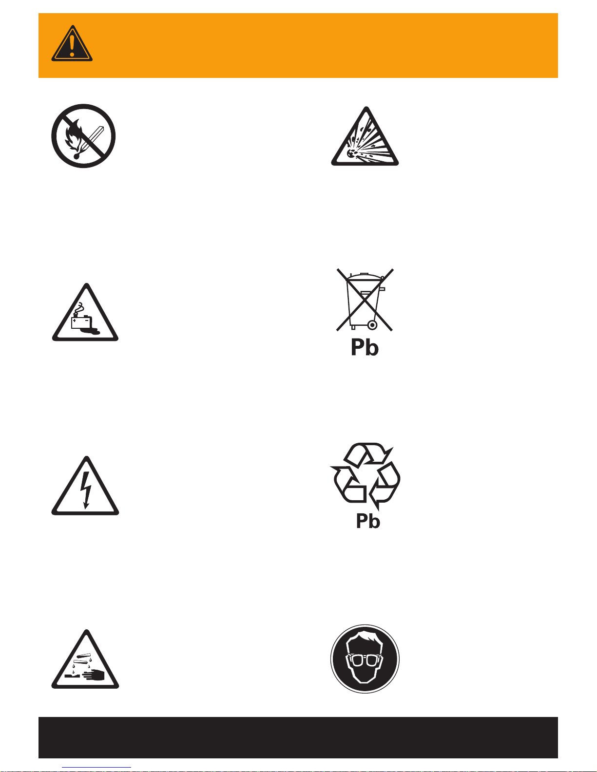
WARNINGS
Keep open flames
away from batteries
on charge.
Risk of battery
explosion.
Be aware of
battery fumes
and electrolyte.
Do not dispose
of batteries in
the garbage.
Electrical hazard
exists inside the
charger, do not
remove the
side cover.
Always recycle lead
acid batteries.
Battery electrolyte
is highly corrosive.
Wear eye protection
when working near
batteries.

3
Contents
Warnings ...................................................................................................................................... 2
Contents
....................................................................................................................................... 3
Overview
...................................................................................................................................... 4
Installation
................................................................................................................................... 5
Operation
..................................................................................................................................... 6
- Front Panel .......................................................................................................................... 8
- Configuration Settings .................................................................................................. 10
Charger Alarms
........................................................................................................................ 11
Battery Alarms
..........................................................................................................................13
Troubleshooting
......................................................................................................................15
Maintenance
..............................................................................................................................17
Spare Parts
................................................................................................................................ 18
Service & Warranty
............................................................................................................... 20
Specifications
........................................................................................................................... 21
Charger Serial Number
Charger Part Number
Date Supplied
Vehicle Model
Purchaser
Purchase Invoice Number
Fleet Number
4
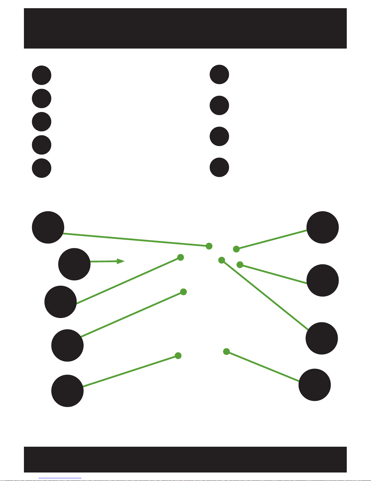
Overview
1
2
3
4
5
Small LED Indicators
Controller Push Buttons
AC Input (Rear)
START/STOP Rocker Switch
6
7
8
9
Filter Cover Assembly
READY/CHARGING
Indicator Lights
Mini USB Port
1 2
3
5
7
4
6
9
Controller Display
FS5 & FS9 XHF Series Charger
8
DC Output
5
Installation
Location
The recommended installation is where the charger(s) can be located
at ground level or on a raised platform, protected against accidental
contact with the lift truck or its forks. Installation above ground level is
recommended to reduce the level of dust ingested by the charger.
AC Input
The FS5 and FS9 chargers require 480V, 3 phase AC supply. Care must be
taken to install your charger with the appropriate rated AC supply cable.
FS5: 6 AWG Copper Conductors
FS9: 6 AWG Copper Conductors, rated 167°F / 75°C minimum
Refer to the rating label on your charger for AC supply requirements
specific to your configuration.
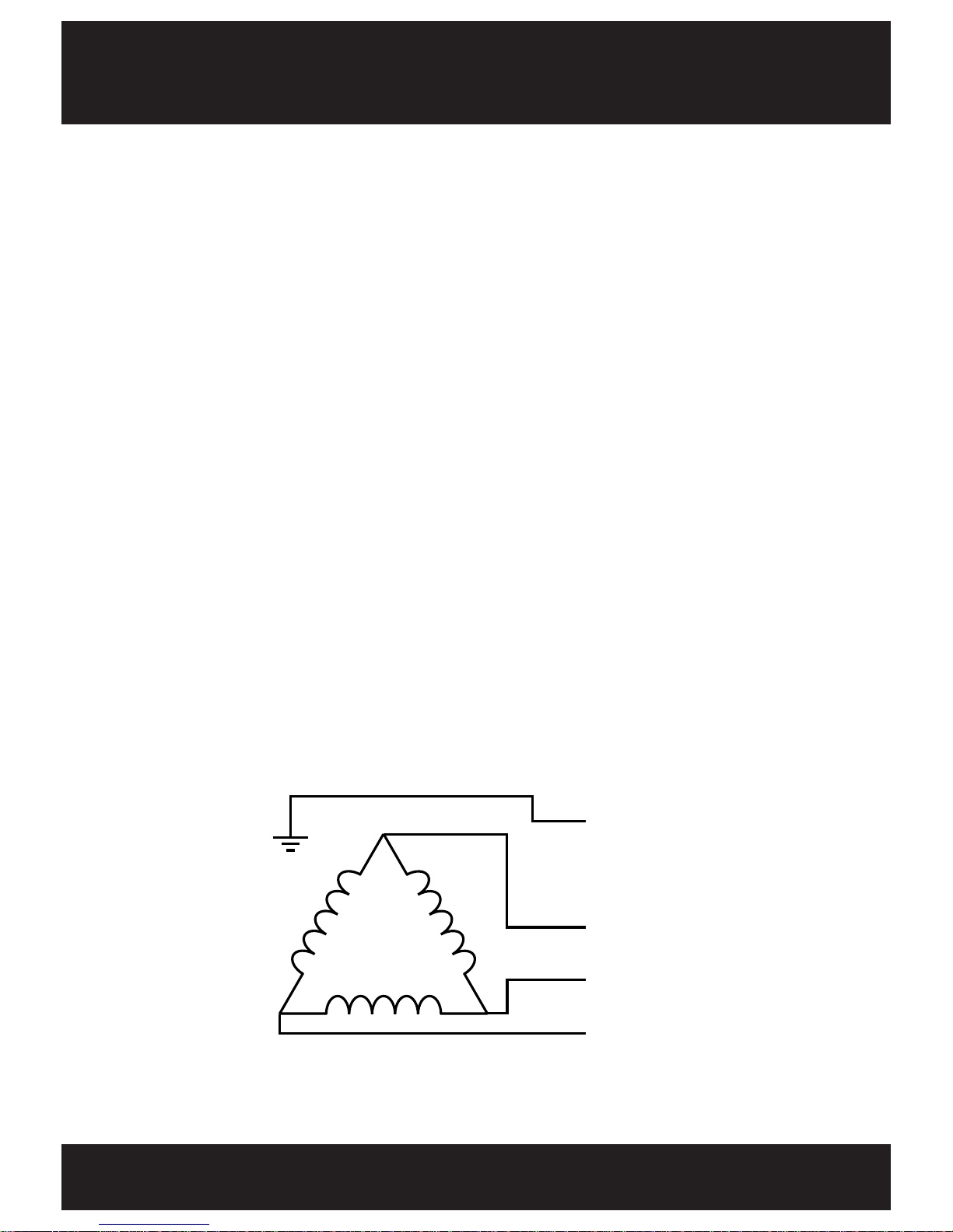
AC Supply Wiring Configuration
E
N
L1
L2
L3
L1
L2
L3
480V AC
Delta
Earth
Note: It is common in the US that a fourth wire (neutral) be used in a
triple phase circuit. If present, it should be attached to the “E” terminal.

6
Operation
Check the battery leads are in good condition before proceeding.
Set the rocker switch to STOP.
Plug the charger in and turn on the AC supply.
Check that the Voltage, Ampere-Hr and Battery Type indicated on
the charger display is appropriate for the battery to be charged.
BMID equipped batteries will automatically configure the charger
provided the charger has APC configuration enabled.
Connect the battery to the charger using the correct cable.
Set the rocker switch to START.
The red CHARGING light will illuminate to indicate charging
has commenced.
When the green READY light illuminates, charging is complete.
Set the rocker switch to STOP and then disconnect the battery
from the charger.
* A battery module may be either an Automatic Profile Configuration (APC) module
or a Battery Monitoring Module (BMM).
8
7
1
2
3
4
5
9
6
The XHF Series charger can be paired with a battery-mounted module*
allowing automatic charge-configuration of the charger as well as
additional data logging features. The battery module is required for any
FS9 charger, or any XHF Series charger configured for Fast or High Rate
charging. Refer to your battery module manual for correct installation and
operation of your battery module with this charger.
7
3
4
8
2
6
9
7
5
1

8
Front Panel
When a Non-Urgent Alarm is indicated the charge cycle has still
completed and in most cases can be disregarded.
When an Urgent Alarm is indicated, the charge cycle has not been
completed and the occurrence should be reported to a supervisor.
Controller display
Displays information depending on the status of the charger.
1
4
START/STOP rocker switch
0 = Stop charge.
I = Start charge.
5
READY/CHARGING indicator lights
RED steady on, GREEN off = Charging.
RED off, GREEN steady on = Charge complete.
RED flashing, GREEN off = Non-Urgent Alarm.
RED flashing, GREEN flashing = Urgent Alarm.
3
Mini USB port
2
Controller push buttons (Set Equalize Charge)
To enable equalize next cycle, plug in the battery but before setting
the rocker switch to START:
- Press
button to set equalize next cycle
- Press ENTER to allow changing
- Press
to select “Enable”
- Press ENTER to accept change
- Press
to select “Store”
- Press ENTER to accept
- Press
to return to “Connect Battery”
- Set the rocker switch to START

9
Display when no battery
connected or rocker
switch set to STOP.
Display when
charging.
Display when charge
complete.
AMBER LED same
as GREEN indicator.
GREEN LED
illuminates when
charger is powered up.
RED LED same
as RED indicator.
UP
button.
ENTER
button.
DOWN
button.
48V
Flooded
200Ahr
40A
Config:
Voltage
Amphrs
Profile
Current
Charging
Flooded
57.6V
40A
Rolling
Display:
Current=
Amphr=
Charge Time=
State=
Batt Volt=
Cell Volt=
Complete
Finish Time=
04:30:15
Rolling
Display:
Charge Time=
Bulk Time=
Finish Time=
Termination=
Batt Volt=
Cell Volt=
Finish Volt=
Amphrs=
1
2
3
4
5

10
Configuration Settings
Charge Profiles Available:
Conventional Charge IUIa/IEI
Opportunity Charge
Fast Charge (battery module required)
Battery Types: Flooded, Sealed, Gel.
Environments: Standard, Freeze/cold condition.
Cable Length: Combined charger and battery cable length in metres.
Equalize Charge Settings:
Cycle count:
Adjustable to any number. Default setting is to equalize
charge after every 5 complete charge cycles.
Day/time: Select day and time of the week to trigger an equalize charge
on the next charge cycle. Can also select to have it equalize
charge every other week.
Manual equalize: Select to have an equalize charge run from the display panel.
Contact your local Eco Charge / Dealer for assistance with the adjustment
of these settings.
Ampere-Hour Ranges:
FS5 FS9
Low limit (Ahr) Upper Limit (Ahr) Low limit (Ahr) Upper Limit (Ahr)
Conventional Profile (16A/100Ahr)
24V 300 1875 300 3375
36V 300 1875 300 3375
48V 300 1575 300 2810
Opportunity Profile (25A/100Ahr)
24V 300 1200 300 2160
36V 300 1200 300 2160
48V 300 1000 300 1800
Fast Profile (40A/100Ahr)
24V 300 750 300 1350
36V 300 750 300 1350
48V 300 625 300 1125

11
Inlet Filter. Non-Urgent Alarm, can give warning as to when the inlet filter needs
servicing but is not enabled by default.
Low Mains. Non-Urgent Alarm, gives an indication of variation in the input mains
voltage without actually affecting the ability of the charger to provide rated output.
Can also indicate a charger module being overloaded.
Non-Urgent Module Fail. Non-Urgent Alarm, there is a charger module that is
not providing output but the charger is still operating, but redundancy has been
lost.
Module Fan Fail. Non-Urgent Alarm, in the event of a complete failure of the cooling
fans the effected module will back off the maximum output current available to
level where natural convection of heat will allow the module to continue operating.
Module Over Temperature. Urgent Alarm, normally related to a blocked filter or
restricted exhaust air or installation in an inappropriate location.
Charger Alarms
Main Switch
Inlet Filter
Low Mains
Mains Fail
Non-Urgent Module Fail
Urgent Module Fail
Module Fan Fail
Module Over Temperature
Configuration Error
Output Fuse
No Output Current
Monitor ADC Fail
APC Communications Fail
APC Water Level Low
APC Voltage Imbalance
APC Water Level Low. Non-Urgent Alarm, for APC equipped batteries, indicates
the APC Electrolyte Sensor has detected a low level of electrolyte.
APC Voltage Imbalance. Non-Urgent Alarm, for APC equipped batteries,
indicates the midpoint voltage varies from nominal by more than 0.5V. APC will
schedule an equalize charge to rectify this variation.
Main Switch. Urgent Alarm, shows the status of the front panel START/STOP
rocker switch.
Urgent Module Fail

12
Configuration Error. Urgent Alarm, the charger cannot meet the target current
required by the controller even with all fitted charger modules operating or the
configuration does not meet the limits set for the selected AC supply.
Output Fuse. Urgent Alarm, a blown fuse in nearly all cases is caused by
connecting a reverse polarity battery to the charger. When a fuse is blown, check
all batteries for reverse cable connection. A common problem is with first charge
of shift
batteries that have not been previously tested in a lift truck. After replacing
a battery or charger cable always closely check the polarity before plugging the
battery onto the charger.
No Output Current. Urgent Alarm, the charger is not providing the expected
output current. Generally related to a premature disconnection of the battery, but
also could be an incorrectly inserted charger module.
Monitor ADC Fail. Urgent Alarm, internal watchdog of the controller’s microcontroller indicating a major fault and potentially unpredictable behaviour if the
charger is left running.
APC Communications Fail. Urgent Alarm, the APC module has failed to
communicate with the charger.
APC Incorrect Voltage.
Urgent Alarm, the charger cannot produce the voltage
required by the APC.
APC Unknown Charger. Urgent Alarm, the charger cannot find the required
pro
file required by APC.
Charger Alarms - continued
Mains Fail. Urgent Alarm, a mains loss situation and the charge cannot proceed.
Urgent Module Fail. Urgent Alarm, if the number of charger modules not providing
output equals or exceeds the setting for urgent module count in the monitor tab
then the charger will stop. If urgent module count is set to one then the charger is
configured without redundancy and a single fault will interrupt the charge cycle.

13
Deeply Discharged Battery. Non-Urgent Alarm, the battery at start is under
1.9V per cell but recovers within 30 secs of charge, normally comes up when the
battery is quickly unplugged from the lift truck and plugged into the charger.
Finishing Charge Timeout. Non-Urgent Alarm, the battery has exceeded the
maximum time allowed for the finishing part of the charge cycle. Generally not a
major problem and indicates
the battery did not quite perform as expected. Not
uncommon with new batteries that are still cycling up to full capacity (allow 10
cycles) however if the alarm is a regular occurrence it needs investigation and
possible adjustment of the charger or service of the battery.
Battery Alarms
Over Discharged Battery
Bulk Charge Timeout
Minimum dV/dt
+dI/dt
Deeply Discharged Battery
Finishing Charge Timeout
Maximum Cell Voltage
Minimum Current
Sulphated Battery
Battery Disconnected
Batt Over Temp - Start
EQ/Refresh Timeout
Incorrect Battery
Reversed Battery
Batt Over Temp - Charge
Minimum dV/dt.
Non-Urgent Alarm, details the change in battery voltage over
time. The alarm occurs when the change in voltage exceeds the value set in
pro
file settings. This alarm also indicates the termination of a successful charge.
Maximum Cell Voltage. Non-Urgent Alarm, occurs when the voltage per cell
exceeds the value set in the profile settings. Typically 2.7V per cell for lead acid
batteries.
Batt Over Temp - Charge. Non-Urgent Alarm, occurs when the battery
temperature measured during a charge profile exceeds the value set in the
controller settings. This alarm will not allow the charge profile to continue.
Minimum Current. Non-Urgent Alarm, occurs when using a IU profile and the
current in the constant voltage stage falls below the value set in the profile settings.
This alarm will not stop a profile and is considered normal for some types of
batteries.
EQ/Refresh Timeout. Non-Urgent Alarm, occurs when the time in a given stage
of the equalize profile has exceeded the value set for that stage of the profile. This
alarm will terminate the equalize charge but is not considered an Urgent Alarm.

14
Battery Disconnected. Urgent Alarm, the battery has been unplugged before
charge cycle has completed. This can damage the battery connector and increase
risks of battery explosions as sparks around batteries at their top of charge whilst
gassing can be very dangerous. If the battery needs to be disconnected mid
cycle, the toggle switch must be first set to STOP. This will stop the charge and
log a partial cycle in the charge log but allows safe disconnection of the battery.
Reversed Battery. Urgent Alarm, a battery with positive and negative cables
reversed has been connected to the charger. Generally this will also cause an
output fuse alarm and the need to replace the charger’s DC output fuse(s). Such
a situation is not covered by warranty as new batteries should always first be
checked for correct polarity BEFORE plugging onto the lift truck or a charger.
Batt Over Temp - Start. Urgent Alarm, occurs when the battery temperature
measured before a charge profile starts exceeds the value set in the controller
settings. This alarm will not allow the charge profile to continue.
+dI/dt. Urgent Alarm, occurs when the measured current in the constant voltage
stage is rising instead of falling. This alarm will terminate the charge profile.
Battery Alarms - continued
Bulk Charge Timeout. Urgent Alarm, the battery has exceeded the maximum
time allowed
for the initial constant current bulk charge phase. Could indicate a
faulty battery or the charger configuration is not correct for the size of battery to
be charged. May need additional charger modules added to the charger.
Over Discharged Battery. Urgent Alarm, the battery is still under
1.9V per cell after
30 seconds of charge which indicates a faulty battery that needs investigation.
Sulphated Battery. Urgent Alarm, deactivated by default.
Incorrect Battery. Urgent Alarm, the battery voltage is inappropriate for the
configuration of the charger and cannot be charged without reconfiguring the
charger to suit the battery. Note: An incorrectly configured APC can cause this
alarm.

15
Troubleshooting
Problem Possible Cause Remedy
Main Switch Alarm
Front panel switch in the STOP
position.
Charge will start when the
switch is set to START.
Inlet Filter Alarm Air inlet filter blocked. Clean the filter.
Low Mains Alarm
AC mains supply is low or
charger modules may be
overloaded.
Check configuration of the
charger suits the application.
Non-Urgent Module Fail Alarm
Charger module not providing
output, there is capacity to
charge at a reduced rate.
Replace the faulty charger
module(s).
Urgent Module Fail Alarm
Faulty charger modules are
affecting the ability of the
charger to charge the battery.
Replace the faulty charger
module(s).
Module Fan Fail Faulty charger module fan. Replace charger module.
Module Over Temperature Charger module is overheating.
Check air inlet filter is not
blocked, check the charger
is installed without any
obstructions to air inlet and
outlet.
Configuration Error
Charger cannot provide the
target output current.
Check the controller
configuration matches the
quantity of power modules
installed, add charger modules
if necessary.
BMID/battery requires more
current than modules or AC
supply can support.
Output Fuse Blown output fuse.
Check battery polarity. Replace
blown fuse.
No Output Current
Charger failing to provide the
required current.
Check operator has not been
unplugging battery mid charge
cycle or the charge profile has
allowed the battery current to
fall below 0.7A.
Monitor ADC Fail
Faulty MPC35 controller
module.
Replace the MPC35
controller module ensuring
the replacement is correctly
configured.

16
Problem Possible Cause Remedy
Low Output Current
Only one battery cable
connected (FS9).
Ensure two battery cables are
connected (FS9 only).
Over Discharged Battery
Battery is <1.9Vpc at
connection but recovers within
30 seconds of charge.
Allow approximately 1 minute
between truck-battery
disconnect and charger-battery
connect. Regular occurrences
might need investigation of
work practices.
No Output Current
Battery unplugged during
charge.
Charge profile allows current to
fall below 0.7A
Ensure battery has not been
unplugged before charge
completion.
Check that the charge profile is
appropriate for the battery type.
Deeply Discharged Battery
Battery is still <1.9Vpc after 30
seconds of charge.
Check battery for faults.
Incorrect Battery
Battery is not the correct
voltage for the charger.
Check the configuration
matches the battery.
Bulk Charge Timeout
The bulk charge part of the
cycle is longer than expected.
Check the charger
configuration matches the
battery, check the battery for
problems.
Finishing Charge Timeout
The finishing charge part of the
cycle is longer than expected.
Check that the charger
configuration matches the
battery, regular timeouts may
indicate a problem with the
battery.
Battery Disconnected
Battery has been disconnected
during charge cycle.
Front panel toggle switch
must be set to STOP before
disconnecting battery.
Reversed Battery
A reverse polarity battery has
been connected to the charger.
Correct the incorrect battery
wiring and replace the blown
charger output fuse(s).
Troubleshooting - continued

17
Maintenance
Provided it is correctly installed in an appropriate location and is not abused, the
charger will require little maintenance. The only requirement is to monitor the air inlet
filter at the front of the charger for dirt accumulation. The charger modules internal to
the charger housing require a good supply of cooling air during the charge cycle and
a blocked filter will affect the cooling. A blocked filter could lead to the charger turning
down its maximum output to prevent overheating of the charger modules. An extremely
blocked filter could cause longer charge times, inability to charge the battery correctly
or premature wear of the charger modules.
Service Interval
The recommended service interval is 6 months but this will vary depending on the
location of the charger and the number of charge cycles performed. The fans in the
charger modules only run during charging and are speed controlled. If the charger
output is small the fans will only be turning slowly. At full power there is a considerable
requirement for cooling air and the fans will be working hard with considerable hot
air being exhausted from the rear of the charger. The exhaust air from the rear of the
charger should never be restricted. The intermittent nature of the fans results in a long
fan service with no scheduled replacement of fans being required.
Intake Filter
The filter material is an electrostatic polypropylene type that is easy to clean with
compressed air to blow out any accumulated dirt and dust. Before attempting to clean
the filter it is necessary to remove it from the housing by unscrewing the two captive
screws and unhinging the filter from the housing. The electrostatic filters provide a
good compromise between filtering and clogging, but a small quantity of dust will enter
the charger modules during normal operation. A small quantity of dust in the charger
modules will generally not cause problems, however excessive accumulation or where
the material ingested is corrosive, conductive or wet will cause issues, resulting in
premature wear of the charger modules.
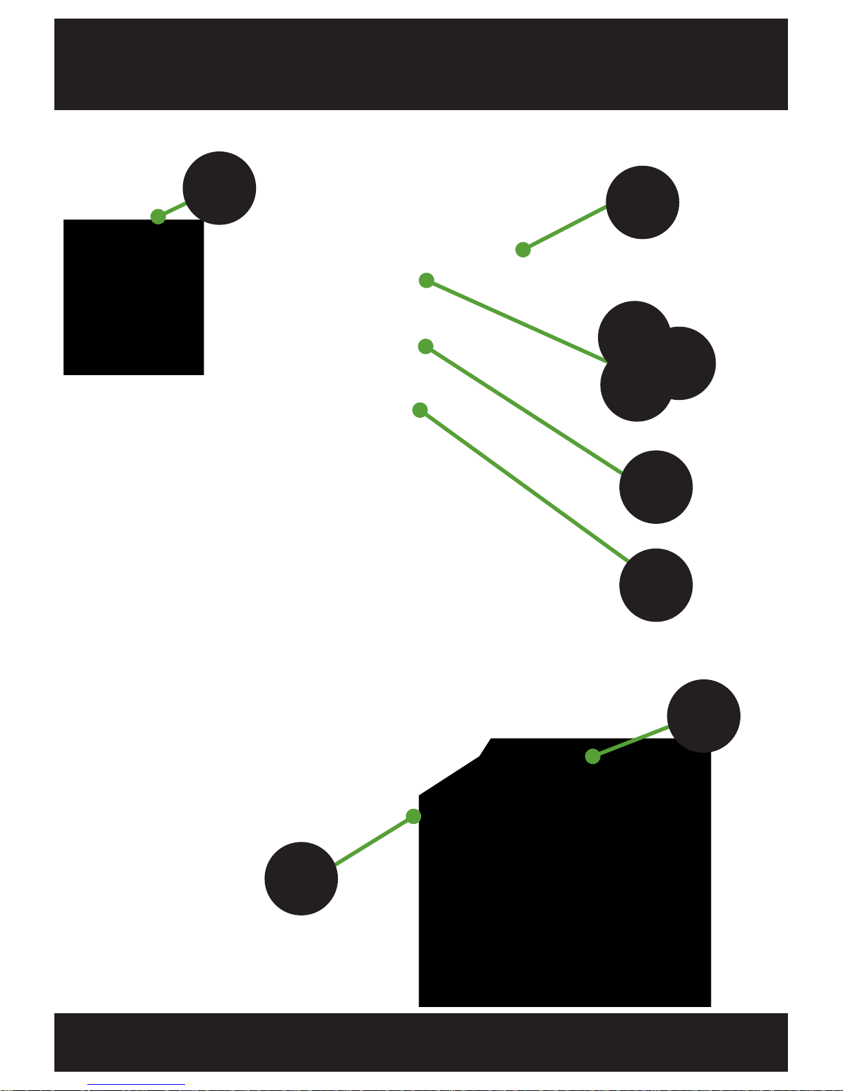
Removing
the filter
from the
housing.
1. Unscrew the 2x
captive screws and
unhinge the filter
from the housing.
2. Blow out any dirt
& dust buildup with
compressed air to
clean the filter.

18
Spare Parts
Image Description
MP330 Module
SM31 Large Display Assembly
MPC35 Main Board Assembly
300A Current Shunt
Current Sense Loom
Voltage Sense Loom
FS5-9 AC Filter Board
Auxiliary PSU
Stud Diode 240A 400V
Fuse HRC180A 150VDC 240VAC
Front Control Panel Membrane
USB Hole Plug

19
Image Description
FS5 Cabinet
FS9 Cabinet
Blanking Plate - Module Bay
Welded Filter Assembly
Front Panel Green Indicator
Front Panel Red Indicator
Front Panel Rocker Switch

20
Service & Warranty
Service
If both the RED and GREEN indicators are flashing there has been an
Urgent Alarm that has prevented the charge cycle from completing. Take
note of the error displayed on the display and contact your servicing battery
dealer or call DC Power Technolgoies (DCPT) at 1-844-ECO-CHRG for
assistance.
If the RED indicator is flashing, but the GREEN indicator is on steadily, the
charge has completed satisfactorily but with a Non-Urgent Alarm. Contact
DCPT only if this is occurring on a regular basis.
Warranty
DCPT warrants that the product is free from defects in material and
workmanship and agrees to remedy any defect (or at its option replace the
product) for a period of one year from the date of purchase. This warranty
covers both parts and labour. Parts may be replaced under this warranty
with new or remanufactured parts.
This warranty will not apply to any product that has been improperly
installed, misused, abused, used in ways the product was not designed,
altered or repaired in any way which may affect the performance or
reliability of operation, sustained damage by power surges or electrical
storms, or sustained shipping damage, or repaired by any unauthorised
repair center.
Please contact DCPT Customer Service to obtain a Returned Materials
Authorisation (RMA) prior to shipping any products for repair. All shipments
must be shipped prepaid and include proof of the date of your original
purchase. Please include your name, address, phone number, email
address and a brief description of the problem.
DCPT makes no other warranties, express or implied, including any
warranty of fitness for a particular purpose. In no event shall DCPT be
responsible for indirect or consequential damages or lost profits even if
DCPT has been advised of the possibility of such damages. DCPTQs sole
obligation shall be the repair or replacement of a nonconforming product.


21
Specifications
FS5 & FS9 Cabinet
Dimensions (in / cm): 13.40W x 18.0D x 26.00H / 340W x 45.7D
x 66.0H
Weight (lbs / kg):
Empty: 71.0 / 32.2 (approx.)
FS5 (5 modules) 95.4 / 43.3
FS9 (9 modules) 123.0 / 55.8
MP330 Modules
AC Input Three phase 480V
Nominal Input Voltage: 380-480V AC
Operating Voltage Range: 340-580V AC
Frequency Range: 45-65Hz >0.92PF
Typical Efficiency: Max. 93% @ 48V
DC Output Range: 25-65V DC
60A DC output up to 50V
52A DC output to 57.6V
Ripple: <2mV
Broadband Noise: 2mV (<100hz)
200mV p-p (0-22Mhz)
Environmental Requirements
Ambient Temp. Range: -50ºF to 104ºF
(max. output power is derated above 122ºF)
Storage Temperature: -68ºF to 158ºF
Humidity: 5-95% RH (non-condensing)
Compliances
UL Listed: E333392 - UL 1564
California Appliance Large Battery
Efficiency Program: Charger Systems
BC
C
A
L
I
F
O
R
N
I
A
E
N
E
R
G
Y
BC
C
O
M
M
I
S
S
I
O
N
C
O
M
P
L
I
A
N
T

22
Notes

23
Notes

 Loading...