

Enatel PSX24042, PSX2404221F-200, PSX2404211F-000, PSX2404211F-200, PSX2404221F-000 Installation Manual
...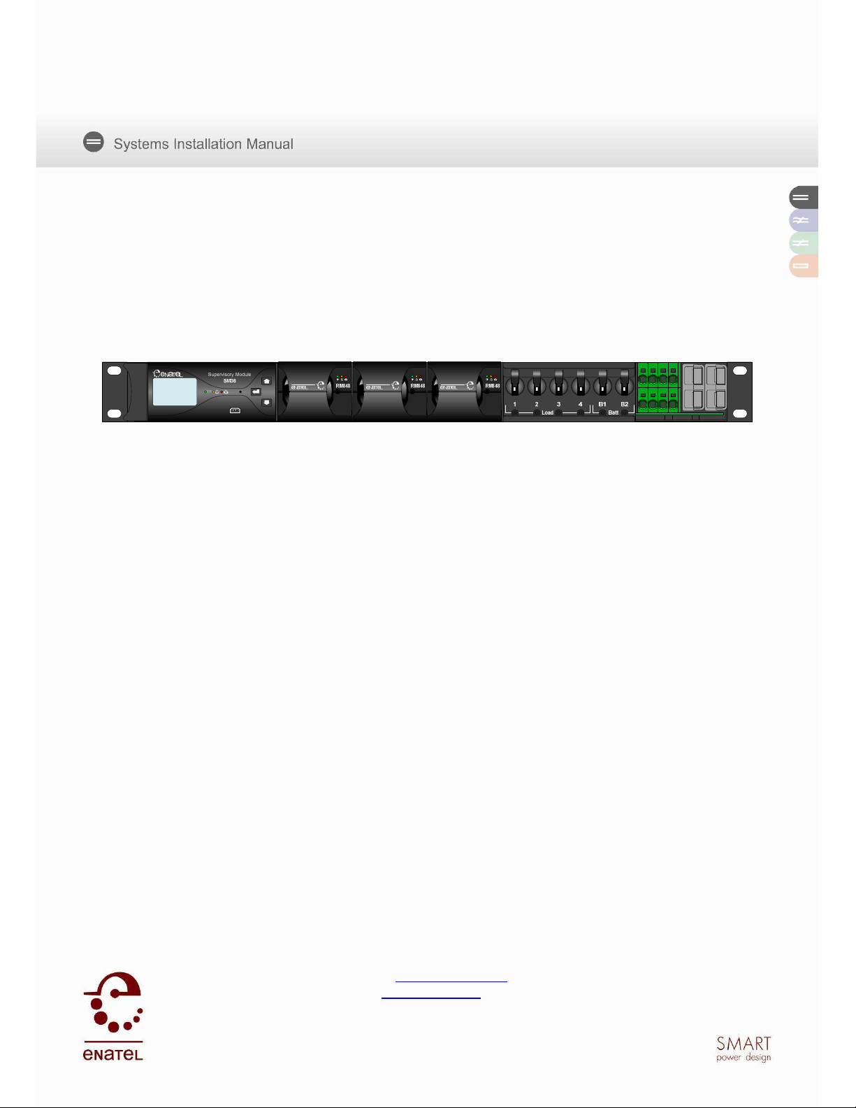
1U MICRO Compact System
PSX24042x1F-x00 &
PSX24051xF-x00
Installation Manual
V2.1
Manufactured by Enatel Ltd.
321 Tuam Street
PO Box 22-333
Christchurch
New Zealand
Phone +64-3-366-4550
Fax +64-3-366-0884
Email sales@enatel.net
www.enatel.net
Copyright © Enatel Ltd. 2010
Enatel DC System Manual Page 1 of 31

TABLE OF CONTENTS
1.0 Scope .............................................................................................................................. 4
2.0 System Overview ............................................................................................................. 5
3.0 Installation ....................................................................................................................... 6
3.1 Unpacking & Installing in 19” Rack ............................................................................... 6
3.2 Installing in ETSI Rack ................................................................................................. 6
3.3 AC Cabling ................................................................................................................... 7
3.3.1 Upstream Over-current Protection ......................................................................... 7
3.4 DC Cabling ................................................................................................................... 9
3.5 Alarm/Ancillary Cabling .............................................................................................. 10
4.0 Alarm Mapping to Volts-free Relays ............................................................................... 12
5.0 Circuit Breaker Fail Monitoring ....................................................................................... 13
6.0 LVD Operation ............................................................................................................... 14
7.0 DC Earthing ................................................................................................................... 15
8.0 Commissioning .............................................................................................................. 16
8.1 System Pre-check: ..................................................................................................... 16
8.2 Rectifier Start-up ........................................................................................................ 16
8.3 Battery Start-up .......................................................................................................... 16
8.4 Load Start-up ............................................................................................................. 16
8.5 DC System Commissioning Check-List ...................................................................... 18
9.0 Maintenance .................................................................................................................. 22
10.0 Appendix 1 - Rectifier Input Fuse Curves ....................................................................... 23
11.0 Appendix 2 - System Wiring Diagrams ........................................................................... 24
Appendix 3 - AC Input Transient Protection .............................................................................. 28
Appendix 4 - Model Specifications ............................................................................................ 30
11.1 System Part Numbers - 3 Rectifier ............................................................................. 30
11.2 System Naming Convention ....................................................................................... 31
Enatel DC System Manual Page 2 of 31

Receiving Instructions
CAUTION:
We present all equipment to the delivering carrier securely packed and in perfect condition.
Upon acceptance of the package from us, the delivering carrier assumes responsibility for its
safe arrival to you. Once you receive the equipment, it is your responsibility to document any
damage the carrier may have inflicted, and to file your claim promptly and accurately.
For your protection, the following information and the product manual should
be read and thoroughly understood before unpacking, installing and using the
equipment.
Package Inspection
• Examine the shipping crate or carton for any visible damage: punctures, dents and any
other signs of possible internal damage.
• Describe any damage or shortage on the receiving documents and have the carrier sign
their full name.
Equipment Inspection
• Within fifteen days, open crate or carton and inspect the contents for damages. While
unpacking, be careful not to discard any equipment, parts or manuals. If any damage is
detected, call the delivering carrier to determine the appropriate action. They may require
an inspection.
Save all the shipping materials for the inspector to see!
• After the inspection has been made and you have found damage, call us. We will determine
if the equipment should be returned to our plant for repair or if some other method would be
more expeditious. If it is determined that the equipment should be returned to us, ask the
delivering carrier to send the packages back at the delivering carrier’s expense.
• If repair is necessary, we will invoice you for the repair so that you may submit the bill to the
delivering carrier with your claim forms.
• It is your responsibility to file a claim with the delivering carrier. Failure to properly file a
claim for shipping damages may void warranty service for any physical damages later
reported for repair.
Handling
Handle the equipment with care. Do not drop or lean on front panel or connectors. Keep away
from moisture.
Identification Labels
Model numbers are clearly marked on all equipment. Please refer to these numbers in all
correspondence with Enatel.
Enatel DC System Manual Page 3 of 31

1.0 S
COPE
This manual covers essential information for the installation and commissioning of the 1U
MICRO Compact Enatel Compact DC Power System Range (see Appendix for individual model
specifications).
System set-up for the rectifiers, alarms etc., are provided in separate manuals for the SM35/6
supervisory module and RM848 rectifier.
All installation and maintenance must be carried out by suitably qualified personnel.
Note: The 1U MICRO Compact system is available with positive earthing (fixed) or
positive/negative earthing (user selectable - negative earth as default). The installation
manual covers both earthing varieties, the standard system is assumed to be fixed
positive earthing. Where parameters and settings differ between systems, the negative
earthed system parameters will be specified within parenthesis i.e.( ).
Enatel DC System Manual Page 4 of 31

2.0 S
Systems with a model number beginning with PSX24 can hold three rectifier modules and have
a maximum power output of 2.4kW, producing a maximum current output of 44.4A at 54Vdc.
The system is intended to be a complete power system in a box, so no connections need to be
made internally. AC connection is via rear exiting lead with all the DC (Load and Battery)
connections are made at the front of the unit. Alarm connections are accessible from the front.
The system is designed to be extremely simple to install and set up.
The following is a summary of the system:
- Overall size is 483mm wide (19” standard mounting) x 44.5mm high (1U) x 280mm deep
- Optional ETSI mounting tabs included
YSTEM OVERVIEW
(within ETSI specification)
- Up to 3* RM848 series rectifiers - may be packaged separately
- SM3x supervisory module (fully integrated in the system)
- Battery Low Voltage Disconnect fitted as standard (80A rating).
- Up to 2*x 30A Battery Circuit Breaker, this may be specified as different values (from 2A to
30A) at time of order.
- Up to 4*x Load Circuit Breaker, this may be specified as different values (from 2A to 30A) at
time of order. If only one Battery Circuit Breaker is fitted, a 5th load breaker can be specified
at time of order.
- System weight is approximately 3.6kg without rectifiers, and 5.6kg with three rectifiers fitted.
- Single phase lead supplied for input termination (phase, neutral and earth)
- Front or rear cable access
*values shown are maximum values and depend upon model selected. Please see model
numbers and descriptions in the appendix of this manual.
Note:
The user selectable, positive/negative earth system has the DC Common (earth
This system is supplied with the AC and DC earths connected. The standard system
(+ve earth system) output has the DC Common (earth connection) in the positive side
of the circuit.
connection) in the negative side of the circuit, but can be changed by following the
instructions in the DC earthing section of this manual.
The earth link can be completely removed from the system to isolate earths. Please
see the DC earthing section of the manual.
Enatel DC System Manual Page 5 of 31

3.0 I
NSTALLATION
3.1 Unpacking & Installing in 19” Rack
Upon unpacking, check that the unit is not damaged, and that you have the required number of
rectifiers.
Remove the transport bracket supplied attached to the top of the system.
The unit fits into a standard 19” mounting frame. The mounting screws should be M6, however
M5 may be used with washers. Be sure to mount the unit in the 19” frame squarely if M5
screws are used.
To fit the cover, remove the screws securing the top of the system and place on, allowing the
rear tabs to lock into the slots provided. Secure the cover to the chassis by replacing the
screws. The rack will be able to securely hold the 1U system with just the bottom two screws
fitted. Brace cabinet mounting if necessary.
Please note the complete system weight is 5.6Kg. Ensure the 19” mounting rails are able to
withstand mounting of the system. The supplied transport bracket can be utilised in cabinets
with 19” mounts at the rear of the cabinet to increase the system mounting rigidity if required.
3.2 Installing in ETSI Rack
Fit ETSI mounting tabs to each side of the compact system chassis. Attach the tabs to the
desired depth with the included M5 Screws. Screws are accessible from the inside of the
system and as such ETSI mounting tabs can only be fitted prior to installing in a rack.
Fig 1, Fitting of ETSI rack mount tabs
Fig 2, Fitting of ETSI rack mount tabs
Note: Fitment of tabs in some positions will require the temporary removable of the DC Battery
connectors and SM3x monitor. These can be replaced once fitment is complete.
Enatel DC System Manual Page 6 of 31
3.3 AC Cabling
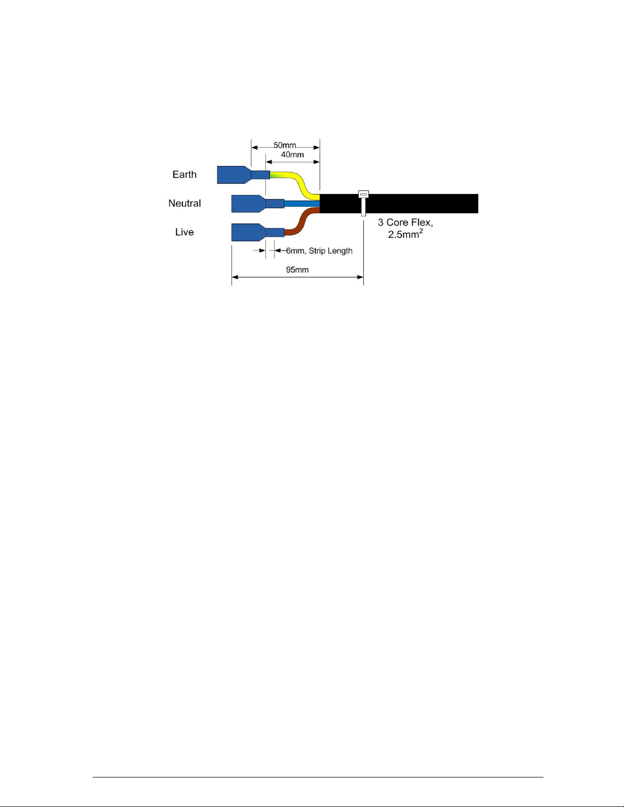
The AC cables are clearly labelled at the rear of the system (see Fig 3). The AC cable provided
is 2.5mm2 cables and suitable terminals should be used.
AC connection internally is via 6.4mm QC tabs. Longer cables can be easily fitted by replacing
the existing cable. Ensure that the AC colour coding is correct for the country of fitment:
Fig 3, AC Cable Detail
Connections should allow for a maximum single phase AC supply of 15A (@ 175VAC) (see next
section).
The AC earth is internally bonded to the system chassis.
DC Common is connected to the AC earth through the placement of the PCB connecting the
backplane to the distribution. Alignment depends on required earthing connection. Please see
the DC earthing section of this manual for more detail.
Note: Please refer Appendix 3 for AC Input Transient Protection.
3.3.1 Upstream Over-current Protection
There are two considerations to take into account when selecting an appropriate fuse/circuit
breaker.
- The upstream protection should protect the downstream cable from overload situations.
- Discrimination should be maintained with the downstream device fuses.
(i) Cable Rating
The maximum current drawn by the DC power system is 15A (5A per rectifier at a minimum
input voltage of 175Vac and full output power). The upstream protection device must be able to
supply this load under all conditions without tripping. Therefore, typically at least 20%
headroom is allowed for in the protection device, making its minimum rating 18A.
Note: The current carrying capacity of cables is dependent on the type of cable used. Please
check with your local supplier and local regulations for appropriate sizing.
For convenience, the system is supplied with a 1.0m long, 3-core, 2.5mm2 flex already
attached. This has a current carrying capacity of 20A.
(ii) Discrimination
Discrimination ensures that the upstream circuit breaker or fuse does not blow if a rectifier input
fails (short circuit). Therefore it is important to ensure the upstream protection discriminates
with the internal fuse of the rectifier. The fuse used in the RM848 is a slow-blow 10A fuse. The
tripping curve for this is shown in Appendix 2 at the rear of this manual.
Enatel DC System Manual Page 7 of 31

A minimum circuit breaker to use for this system is a 20A, D-curve (note, a 20A C-curve breaker
will not discriminate with the rectifier fuse). Therefore, when used with the 2.5mm2 cable
supplied, a 20A, D-curve breaker should be used.
Alternatively, a 32A C-curve breaker, or greater, can be used. However, AC cable provided
may have to be replaced for a larger cable1.
If a fuse is used upstream, then any BS88 or NH g style fuse, of 20A or greater rating will
discriminate.
1
NOTE:
A larger breaker may be used even though in theory it may appear that the 2.5mm2 wire is not fully protected. In fact
it is protected on two accounts. Firstly it is protected by the rectifier input fuse (which is only a short distance away). Secondly,
the rectifiers are power-limited on their input. Therefore, they can never be overloaded. As a result, the wire can never be
over-loaded by the rectifier – it can only see fault current. As a result, depending on local authorities, only fault current
protection may be catered for by the upstream protective device.
Enatel DC System Manual Page 8 of 31
3.4 DC Cabling
CAUTION:
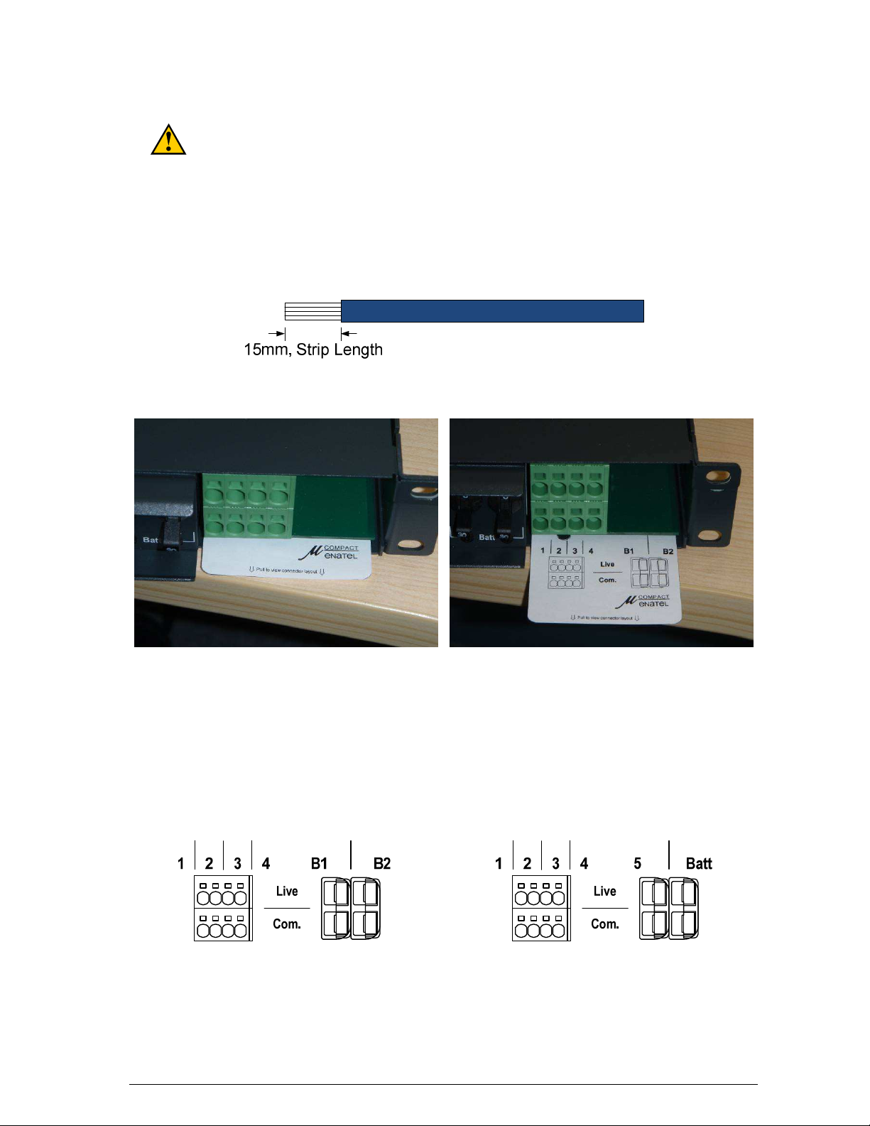
All DC Load cables terminate to the connectors at the front of the unit as shown in Figure 5.
These terminals are all 6mm2. Load connections are of a ‘push in’ design and cables can be
simply pushed into the connector for termination after stripping to the appropriate length.
Removal requires a small screwdriver to be inserted into the rectangular hole above the
connector whilst pulling on the cable.
Connector designators are available on the pull-out guide. See Figures 4, 5 and 6 for detail.
Use extreme care when fitting batteries & their connections. Remove all jewellery
and rings from oneself prior to commencing the installation. Always use insulated
tools when fitting batteries and take extreme care not to short terminals when
working on them.
Fig 4 & 5, DC Connector detail and pullout guide
The battery cabling connects through the SB50 style power-pole connectors. From here it goes
directly to the appropriate circuit breaker, then via a Low Voltage Disconnect relay and current
shunt to the internal live bus. This can be seen in the appropriate wiring diagram as the rear of
this manual.
Note: Systems with only one battery breaker specified can be fitted with an additional load
breaker. Connection to the output from this breaker is made through the remaining SB50
power-pole.
Connector layout for PSX24042x1F-x00 Connector layout for PSX24051x1F-x00
Fig 6, DC Connector detail
Enatel DC System Manual Page 9 of 31

3.5 Alarm/Ancillary Cabling
Alarm and communication cables terminate directly into the connectors of the Supervisory
Module, SM35 or SM36, which terminals are assessable by pulling the monitor forward to
expose connections (see Fig 7 & 8).
Cables can be routed through the front of the system via the cable exit indicated. When routing
the cables, ensure they are kept away from the AC and DC power cables when possible.
Fig 7. For removal, pull monitor forward to release the ball catch.
Fig 8. SM3x cable access
Relays 1- 6 can be used for normally open or normally closed states by jumper selection. The
relay states labelled NO or NC are for their de-energised state. If an alarm is programmed for
the relay to be normally energised (as may be required in the case of a low voltage alarm where
loss of power will put the alarm into its active state), then be sure to connect the remote wiring
appropriately.
For full monitor functionality and operation information, refer to the appropriate monitor manual.
Uncoil the battery temperature sensor and place in the middle of the middle battery string. If the
lead is not long enough, ordinary 2-core copper (approx. 0.75mm2) wire can be used as an
extension. The purpose of the battery temperature sensor is to monitor the ambient
temperature of the batteries over long periods of time and adjust the rectifier output (float)
voltage accordingly. As a result, it is not necessary to have the temperature sensor touching
the batteries. If the Battery Temperature Sensor is removed a “battery temp fault” alarm is
generated.
Enatel DC System Manual Page 10 of 31
 Loading...