

Page 1
es
ENARCO, S.A.
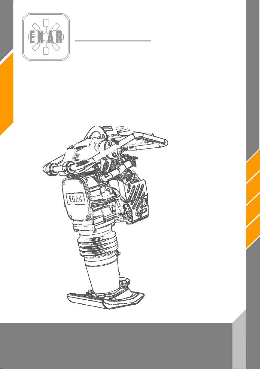
PISONES
PH60 - PH70 - PH80
MX-PH-1301
Manual de instrucciones
Page 2

1
es
PH60 - PH70- PH80
ÍNDICE
1 PRÓLOGO 2
2 INFORMACIÓN DE SEGURIDAD 3
2.1 SEGURIDAD EN LA OPERACIÓN DE LA MÁQUINA 3
2.2 SEGURIDAD EN LA OPERACIÓN DEL MOTOR 3
2.3 SEGURIDAD EN EL SERVICIO 4
3 ¿QUÉ MÁQUINA ES LA MÁS ADECUADA PARA CADA TRABAJO? 4
4 MEDIDAS ACÚSTICAS Y VIBRATORIAS 5
5 PUESTA EN MARCHA, FUNCIONAMIENTO Y MANTENIMIENTO DE LA MÁQUINA 5
5.1 ANTES DE INICIAR EL TRABAJO 5
5.2 PUESTA EN MARCHA 5
5.3 TRABAJO 6
5.4 PARADA 6
5.5 SERVICIO DE MANTENIMIENTO Y ALMACENAMIENTO 7
5.6 LOCALIZACIÓN Y REPARACIÓN DE AVERÍAS 9
PISONES
6 EN CASO DE AVERÍAS 12
6.1 INSTRUCCIONES PARA PEDIR REPUESTOS 12
6.2 INSTRUCCIONES PARA SOLICITAR GARANTÍAS 12
7 PLACAS E INDICATIVOS/PLATES AND INDICATIVES/PLAQUES ET INDICATEURS/PLATTEN UND
KENNZEICHEN 13
8 ESPECIFICACIONES TÉCNICAS / TECHNICAL DATA / SPECIFICATIONS TECHNIQUES /
TECHNISCHE DATEN 14
Page 3

es
2
PH60 - PH70 - PH80
1 PRÓLOGO
Agradecemos la confianza depositada en la marca ENAR.
La lectura del presente manual es importante para el completo conocimiento de las
características y operaciones de trabajo de la bandeja compactadora. Antes de comenzar a trabajar
con esta máquina o de realizar operaciones de mantenimiento en ella lea, comprenda y cumpla las
instrucciones de seguridad de este manual.
En caso de pérdida de este manual o de necesitar un ejemplar adicional solicítelo a ENARCO o
acceda a él en formato electrónico en la página web de ENARCO:
Los procedimientos correctos de mantenimiento aseguran la larga duración y un excelente
trabajo de la unidad.
Aunque el presente manual da algunas indicaciones acerca del motor, recomendamos la
consulta del manual de instrucciones del motor, en lo que al mantenimiento y reparaciones del
motor se refiere.
Si necesita información acerca de la operación o mantenimiento de esta máquina póngase en
contacto con el servicio de asistencia de ENARCO llamando por teléfono, enviando un fax,
realizando una consulta por correo electrónico a
apartado
Servicio ENAR.
[email protected] o a través de la página web en el
http://www.enar.es e imprímalo.
PISONES
Page 4

3
es
PH60 - PH70- PH80
!
!
2 INFORMACIÓN DE SEGURIDAD
2.1 SEGURIDAD EN LA OPERACIÓN DE LA MÁQUINA
El uso o mantenimiento incorrectos del equipo pueden generar situaciones de peligro. Lea y
asimile las instrucciones de este apartado antes de empezar a trabajar con esta máquina. El
operador del equipo debe responsabilizarse de que sabe trabajar con seguridad el equipo. Si
tiene dudas solicite instrucción a personal conocedor de la máquina o contacte con ENARCO.
• El motor se calienta mucho durante su funcionamiento, déjelo enfriar antes de tocarlo.
• No deje nunca la máquina en marcha sin atención.
• El operario debe usar ropa de protección y protecctores auditivos.
• Impida el acceso al área de trabajo de personal no autorizado.
• Asegurese de que sabe desconectar la máquina antes de poner el motor en marcha por si se
encuentra en dificultades.
• Pare la máquina antes de transportarla.
• No intente levantar el equipo sin ayuda. Solicite ayuda o emplee un aparato de elevación
usando el asa de izado integrada en la jaula de la bandeja.
• No utilice el equipo si no se encuentra en buenas condiciones físicas.
• Almacene el equipo de modo adecuado en un lugar limpio y seco cuando no lo vaya a usar.
PISONES
2.2 SEGURIDAD EN LA OPERACIÓN DEL MOTOR
A causa de su alta inflamabilidad los combustibles son especialmente peligrosos. Su uso
inadecuado puede graves daños personales y materiales. Cumpla SIEMPRE con las siguientes
reglas de seguridad:
• No haga funcionar el equipo dentro de un edificio o zonas cerradas de no existir un ventilación
adecuada. En caso contrario puede sufrir intoxicación por monóxido de carbono con perdida
de conocimiento, pudiendo llegar hasta la muerte.
• Antes de rellenar el depósito de combustible, pare el motor y déjelo enfriar unos minutos.
• No debe fumar durante el funcionamiento de la máquina, ni durante el repostaje.
• No rellene el depósito cerca de una llama abierta y rellénelo en un área bien ventilada.
• Sustituya inmediatamente el tanque de combustible si no es hermético, podría ser causa de
explosiones.
• Si durante el repostaje se derrama carburante empápelo en arena. Cámbiese de ropa si le cae
combustible sobre ella.
• Asegúrese de que el depósito de combustible está bien cerrado después de rellenarlo.
• Compruebe que las tuberías y el depósito de combustible no tienen grietas ni fugas.
Page 5
es
4
PH60 - PH70 - PH80
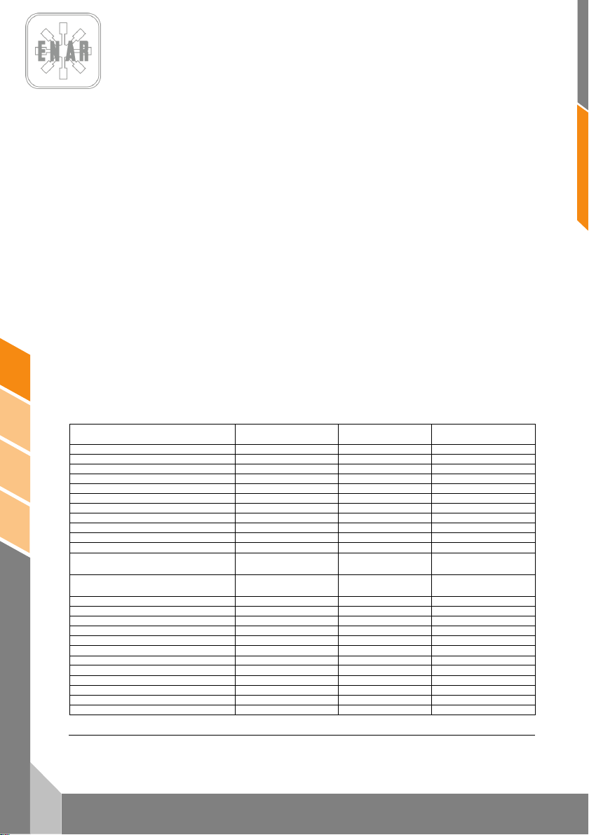
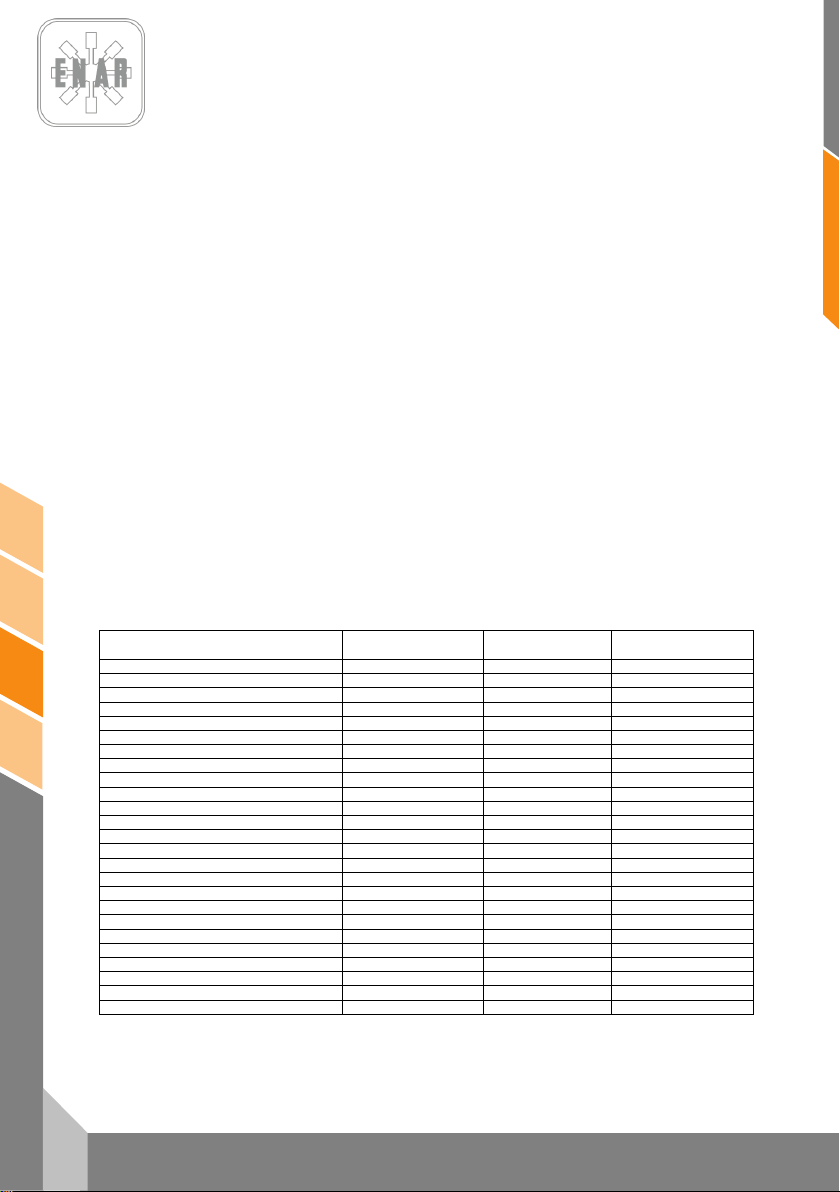
MODELO
APLICACIÓN
Placas reversibles
Placas no
reversibles
Pisones
Áreas de parcheo
#
Fundación de edificios
+
Caminos y paseos
#
Canchas de tenis y deportes
#
Preparación de base
+ # #
Soporte final de puentes o rampas
+ + #
Cruce de ferrocarriles
+ + #
Bloques de cemento entrelazados
# +
Construcción de redes
+ # +
Construcción de drenajes
+ +
Compactación de zanjas.
+ +
Reparación de huecos por rotura de
tuberías, cables, etc.
# + Alrededor de tuberías, cables,
drenajes, etc.
Relleno de rocas
Grava + +
+
Arena o material volcánico
+ + #
Suelos mixtos
+ # +
Fango
+ +
Arcilla +
+
Espesor de capa 0 – 25 cm
+ + +
Espesor de capa 20 – 40 cm
+ +
Mezcla caliente
# + #
Mezcla fría
# + #
Base - Capa de ligado 40 – 100 mm
+ # +
Capa de rodado 25 – 60 mm
# +
2.3 SEGURIDAD EN EL SERVICIO
• No limpie ni revise el equipo estando en funcionamiento.
• No arranque el motor con el cilindro inundado y habiendo retirado la bujía en los motores de
gasolina.
• No compruebe que la bujía da chispa si el cilindro está inundado de gasolina o hay vapores de
gasolina.
• No use disolventes o combustibles para limpiar el equipo, sobre todo en recintos cerrados.
• Mantenga el área próxima al silenciador libre de materiales inflamables.
• Antes de hacer operaciones de servicio en equipos con motor de gasolina remueva la bujía
para evitar un arranque no previsto del motor.
• No está permitido el uso del equipo en atmósferas explosivas. El tanque de combustible debe
cerrar herméticamente. En transportes de largo recorrido es altamente recomendable vaciar
de combustible el depósito del motor.
3 ¿QUÉ MÁQUINA ES LA MÁS ADECUADA PARA CADA
TRABAJO?
# # +
# Puede ser usado + Recomendado
PISONES
Page 6
MEDIDAS ACÚSTICAS Y VIBRATORIAS
4
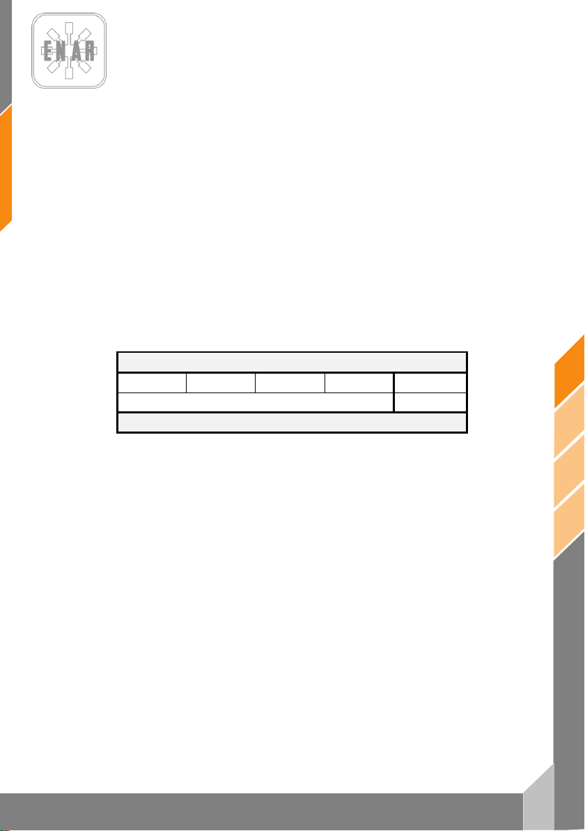
- nivel de potencia acústica según EN 500-4: LWA 106 dB(A)
- nivel de presión sonora según EN 500-4: L
- valor efectivo ponderado de aceleración axial según EN 500-4
96 dB(A)
pA
Ahv 6,8 m/s
2
5 PUESTA EN MARCHA, FUNCIONAMIENTO Y MANTENIMIENTO
DE LA MÁQUINA
5.1 ANTES DE INICIAR EL TRABAJO
5.1.1. Los mecanismos de esta máquina se lubrican por baño de aceite. Compruebe el nivel de
aceite por la mirilla que se encuentra en la parte posterior debajo del fuelle. Agregue aceite si no
fuera posible ver aceite por la mirilla hasta que cubra la mitad de la mirilla.
5.1.2. Llene el tanque de combustible con el tipo de carburante adecuado al motor que equipa
su máquina según la tabla.
MODELO DE MOTOR
HONDA GX120 HONDA GX100 ROBIN ER12 ROBIN EH12 YANMAR L48
GASOLINA SIN PLOMO GAS-OIL A
TIPO DE CARBURANTE
Al llenar el tanque, esté seguro de filtrar el combustible con un colador. No se olvide de colocar el
tapón de llenado y cerrarlo, puesto que el trabajo sin él es peligroso, debido a que se producen
derrames de combustible por la vibración y podría llegar a inflamarse y arder.
5.1.3. Verifique la tensión de cada perno, tuerca o área roscada. Un tornillo flojo debido a la
vibración puede ocasionar un problema serio inesperado. Asegúrese de apretar todas las áreas
roscadas.
5.1.4. Elimine la suciedad y polvo. Limpie especialmente la zona adyacente al arrancador de
retroceso y al pie.
es
5.2 PUESTA EN MARCHA
PISONES
5.2.1. Abra la llave de combustible desplazando hacia abajo la palanca. Cierre la palanca del
regulador de aire y ponga la palanca de la válvula de estrangulación del aire en la posición media
abierta. Para poner en marcha el motor frío desplace la palanca del regulador de aire hasta la
posición de cerrado. Cuando el motor está caliente, el regulador de aire debe estar abierto a medias
o por completo. Si la puesta en marcha del motor resulta difícil, asegúrese de que la palanca del
regulador de aire esté medio abierta para evitar que el carburador sea anegado por exceso de
combustible.
5.2.2. Al tirar de la cuerda de arranque, no apure al máximo toda la longitud, puede dañar el
muelle de recuperación. No suelte la cuerda de golpe para repetir la puesta en marcha una vez
arrancado el motor, mantenga el tirador en la mano y ceda despacio hasta que se recoja
totalmente.
PH60 - PH70- PH80
5
Page 7

es
6
PH60 - PH70 - PH80
5.3 TRABAJO
5.3.1. Después de arrancar el motor, vuelva a abrir completamente de forma gradual la
palanca del regulador de aire. Deje el motor calentarse en velocidad mínima durante 3-5 minutos.
Este procedimiento de calentar el motor en mínimas revoluciones es particularmente importante
durante la temporada fría. Mientras el motor se esté calentando haga una revisión general de la
máquina, para detectar cualquier anomalía.
5.3.2. El pistón comienza a funcionar cuando se gira la palanca del acelerador desplazándola
rápidamente hasta hacer tope. Si la palanca se desplaza lentamente la acción del pisón será
irregular, y se dañará el embrague, EL RESORTE O LA PATA DEL MISMO.
5.3.3. Después de que comienza a funcionar, ajuste el movimiento de vibración de manera tal
que se adecue a la condición particular del suelo, controlando levemente la palanca del acelerador.
Este pisón ha sido diseñado en forma tal que, cuando el motor trabaje a una velocidad comprendida
entre las 3.600 y 4.000 r.p.m., su pata golpea la superficie del suelo a razón de 600 a 700 veces por
minuto, lo que brinda la mejor eficacia del trabajo. Un aumento innecesario de la velocidad del motor
no ocasiona un aumento de la fuerza de compactación, al contrario, la resonancia resultante hace
que la fuerza de compactación DISMINUYA, DAÑANDO LA MÁQUINA.
5.3.4. En tiempo frío, como el aceite que existe en la máquina es viscoso, la resistencia en la
parte alternante es mayor, ocasionando un movimiento algo irregular del pisón compactador. Por lo
tanto antes de comenzar el trabajo se recomienda hacer funcionar la máquina para calentarla
mientras se desplaza la palanca del acelerador repetidas veces entre las posiciones 0 - ¼ de vuelta.
5.3.5. La superficie de la pata en contacto con el suelo se encuentra revestida con una placa
metálica tratada térmicamente. Sin embargo, para compactar canto rodado es aconsejable un
relleno de material fino, arena por ejemplo, en tal forma que el extremo posterior de la superficie
plana de la pata se encuentre EN CONTACTO CON EL TERRENO.
5.3.6. El pisón compactador ha sido diseñado para que avance mientras vibra. Para lograr un
avance más rápido levante la máquina tirando de la misma ligeramente hacia atrás, en forma tal que
el extremo posterior de la superficie plana de la pata se encuentre EN CONTACTO CON EL
TERRENO.
5.3.7. Para suspender el trabajo, e inversamente a la puesta en marcha, desplace rápidamente
la palanca del acelerador de la posición ¼ a 0.
5.4 PARADA
5.4.1. Para suspender el trabajo, e inversamente a la puesta en marcha, desplace rápidamente
5.4.2. Antes de parar el motor, déjelo al ralentí durante 2-3 minutos y luego oprima el botón de
5.4.3. Cierre la llave de combustible poniendo la palanca en posición horizontal.
la palanca del acelerador de la posición ¼ a 0.
parada hasta que el motor se pare por completo.
PISONES
Page 8
7
es
PH60 - PH70- PH80
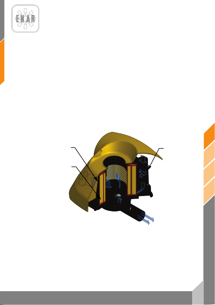
2ª ETAPA
1ª ETAPA
3ª ETAPA
5.5 SERVICIO DE MANTENIMIENTO Y ALMACENAMIENTO
5.5.1. Antes de realizar cualquier servicio de mantenimiento en el pisón compactador, PARE
5.5.2. Servicio de mantenimiento diario:
Elimine completamente de la máquina toda la suciedad, polvo ó aceite. Verifique el filtro del aire,
limpiándolo según requiera. Apriete nuevamente los lugares donde se aprecie una fuga de aceite y
verifique que todas las demás áreas se encuentren apretadas.
5.5.3. Servicio de mantenimiento semanal (cada 50 horas):
Ajuste en la bujía la distancia entre electrodos a un valor igual a 0.7 – 0.8 mm.
Retire el tapón de llenado de aceite (situado encima de la mirilla del nivel de aceite), coloque la
máquina horizontal de manera que el orificio de llenado de aceite sirva para drenaje del aceite
usado colocando la máquina con el orificio hacia abajo para drenar totalmente el aceite.
Coloque la máquina de pie nuevamente y por el mismo orificio eche aceite nuevo mediante un
envasador, hasta realizar el nivel por la mirilla.
El primer cambio de aceite se realizará a las 50 horas de funcionamiento, a partir de la segunda vez
cada 250 horas de trabajo.
5.5.4. Servicio de mantenimiento quincenal (cada 100 horas) o por indicación del sensor de
TOTALMENTE EL MOTOR
mantenimiento del filtro de aire (si está presente):
PISONES
ETAPAS DE FILTRADO
Page 9

es
8
PH60 - PH70 - PH80
3
4
1
2
Suelte las grapas de sujeción (2) Retire la tapa del filtro de aire (1). Extraiga la segunda (3, esponja)
y tercera etapas de filtrado (4, cartucho). Sacuda la tercera etapa y soplela a presión de adentro
afuera. limpie la segunda etapa de filtrado con una solución limpiadora neutra. Después de secarla,
aplique un combustible mixto de gasolina y aceite, y sacuda bien. A continuación, exprima
ligeramente el elemento primario externo (esponja) y colóquelo sobre la tercera etapa para
montarlo, monte el conjunto en la carcasa interior del filtro, coloque la carcasa superior y cierre con
las grapas de sujeción.
5.5.5. Servicio de mantenimiento mensual (Cada 250 horas):
Limpie cuidadosamente cada parte de la máquina y apriete nuevamente los pernos y las tuercas
según se requiera.
5.5.6. Almacenamiento correcto:
Para un almacenamiento prolongado después de que se ha completado un trabajo, drene
completamente el combustible del interior del tanque, del tubo de combustible y del carburador.
Retire la bujía de encendido, vierta unas gotas de aceite en el cilindro y manualmente haga que el
motor dé unas cuantas vueltas, de manera tal que el aceite alcance todos los puntos. Con respecto
al exterior, límpielo con un paño humedecido en aceite.
Almacene la máquina cubriéndola con una funda, en un lugar libre de humedad y polvo y evitando
los rayos directos del sol.
5.5.7. Mantenimiento con sensor del filtro de aire
Si dispone del sensor de carga del filtro de aire, conforme éste se vaya
ensuciando el cuerpo amarillo se irá desplazando hasta llegar a la zona roja
de indicación de necesidad de servicio. Proceda a realizar mantenimiento
del filtro según lo indicado en el punto 5.5.4; rearme el sensor presionando
el pulsador amarillo del filtro.
PISONES
Page 10

9
es
PH60 - PH70- PH80
5.5.8. Funcionamiento del tacómetro.
Con el motor parado la pantalla muestra el tiempo total de
funcionamiento, este tiempo no puede ser puesto a cero. Con el motor
en marcha la pantalla muestra las revoluciones por minuto.
Para ver el tiempo de funcionamiento parcial pulsar el botón “SELECT”.
Para la puesto a cero del tiempo parcial mantener pulsado el botón
“SELECT”, se mostrará el tiempo parcial actual; al soltar el contador se
Con motor diesel:
Alarma de servicio SVC2: después de 50 horas de trabajo el tacómetro mostrará la alarma SVC2.
Realice el mantenimiento prescrito. Para reiniciar el contador pulsar “RESET” tres veces y mantener
pulsado hasta que aparezca RESET en la pantalla.
Alarma de servicio SVC: después de 250 horas de trabajo el tacómetro mostrará la alarma SVC.
Realice el mantenimiento prescrito. Para reiniciar el contador pulsar “RESET” dos veces y mantener
pulsado hasta que aparezca RESET en la pantalla.
5.6 LOCALIZACIÓN Y REPARACIÓN DE AVERÍAS
MOTOR DE GASOLINA
No arranca:
- Existe chispa pero la bujía no da chispa
Existe electricidad en el cable de alta tensión
No existe electricidad en el cable de alta tensión
Compresión satisfactoria
- Existe combustible y la bujía de encendido da chispa
Compresión deficiente
El embrague está bloqueado haciendo que el vibrador gire al intentar arrancar
No existe combustible en el carburador
pondrá a cero.
- Bujía de encendido puenteada
- Depósito de carbón en la bujía de encendido
- Cortocircuito debido a una aislación deficiente de la bujía de encendido
- Separación incorrecta entre electrodos
- Interruptor del botón de paro en cortocircuito
- Bobina de encendido defectuosa
- Aislamiento del condensador deficiente ó en cortocircuito
- Bobina de encendido rota ó en cortocircuito
- Combustible incorrecto
- Ha entrado agua ó polvo
- Filtro de aire deficiente
- Válvula de admisión o escape pegada ó defectuosa
- Aro del pistón ó cilindro gastado
- Culata del cilindro ó bujía de encendido ajustada incorrectamente
- Junta de culata o junta de la bujía de encendido defectuosa
- Tanque de combustible vacío
- La llave de combustible no está correctamente abierta
- Filtro de combustible obturado
- Orificio de ventilación de aire de la tapa del tanque obturado
- Aire retenido en el tubo
- Aguja de entrada del carburador pegada
PISONES
Page 11

es
10
PH60 - PH70 - PH80
Potencia Nula:
- Potencia insuficiente
• Compresión normal y no se observa fallo del encendido
Filtro de aire deficiente
Depósito de carbón en el cilindro
Nivel de combustible en el carburador incorrecto
• Compresión insuficiente
(Vea “Compresión deficiente” más arriba)
• La compresión es correcta pero el encendido es defectuoso
Existe agua en el combustible
La bujía de encendido está sucia
Bobina de encendido defectuosa
La bobina de encendido se cortocircuita a menudo
• Vibrador lleno con exceso de aceite
- Motor recalentado
• Depósito de carbón en la cámara de combustible o en la lumbrera de escape
• Poder calorífico de la bujía de encendido incorrecto
• Aletas de enfriamiento sucias
- La velocidad de rotación fluctúa
Función del arrancador de retroceso deficiente
MOTOR DIESEL (enfriado por aire)
Arranque deficiente:
• Ajuste del regulador incorrecto
• Resorte del regulador incorrecto
• Flujo de combustible deficiente
• Entra aire en el sistema de tubo de succión
- Parte rotativa pegada con polvo
- Fallo del resorte helicoidal
A.- Compresión deficiente
• Compresión nula
Válvula de succión ó escape defectuosa
Ajuste del sistema de descompresión incorrecto
• Apenas existe compresión o es muy baja
Contacto del asiento de la válvula deficiente
Aro del pistón desgastado
Cilindro gastado
Superficie de ajuste del cilindro y de la culata del cilindro defectuosas
B.- No existe una inyección correcta de combustible en
la cámara de combustión
Asiento del inyector flojo
• Flujo de combustible insuficiente ó nulo
Orificio de ventilación de aire en la tapa del tanque obturado
Paso del filtro de combustible obturado y tamiz del filtro obturado
Llave del filtro de combustible cerrada
Aire retenido en el tubo (especialmente cuando el tanque está vacío)
• No existe inyección de combustible en la cámara de combustión
Cilindro de la bomba de inyección ó émbolo pegado
Inyector obturado
Aguja del inyector pegada
PISONES
Page 12

11
es
PH60 - PH70- PH80
• Tanque de combustible vacío
• Entró agua o polvo
C.- Sistema de combustible y compresión, etc., normales, sin embar go no arranca
• No alcanzan la velocidad de arranque
Procedimiento de arranque incorrecto
Viscosidad alta o contaminación excesiva del aceite del motor
Potencia de salida insuficiente. Compresión deficiente:
Aire retenido en el tubo
• Motor recalentado y escape sucio
Aletas de enfriamiento sucias
Agua en el filtro de combustible
Depósito de carbón en la cámara de combustión en la lumbrera de escape
Ajuste de humo incorrecto
Sobrecarga
Regulación del avance de la inyección incorrecta
Inyector obturado
• La velocidad fluctúa
Contacto incorrecto entre la horquilla del regulador y el manguito
Resorte del regulador incorrecto
Placa de balancín y otras partes deslizantes desgastadas o funcionamiento
defectuoso
• La velocidad del motor no aumenta correctamente
Sincronizado de la válvula incorrecta
Lumbrera de escape o silenciador obturado
Sobrecarga
• Encendido defectuoso acompañado por escape blanco
Pistón, Cilindro, Aro gastado
Inyector obturado
Aro del pistón superior e inferior instalados al revés
Regulación del avance de la inyección incorrecta
Sincronización de la válvula incorrecta Junta de la bomba de inyección floja
Junta de la bomba de inyección floja
• Consumo de combustible alto (Se observa escape oscuro)
Fuga en la tubería de combustible
Elemento de filtro de aire obturado
Combustible defectuoso debido a que contiene impurezas
Sobrecarga
• Parte deslizante excesivamente gastada o aro del pistón pegado
Se está utilizando aceite defectuoso
Se descuida el reemplazo del aceite
Elemento del filtro de aire defectuoso o sucio
• Se detiene súbitamente con un ruido anormal
Engrane o daño del pistón o de la varilla
• Aceite lubricante diluido, aumentando su volumen
Cuerpo del émbolo de bomba de inyección gastado
• El motor no se detiene, aun cuando se interrumpe el suministro de
combustible (o causa una sobremarcha)
Aceite excesivo
Instalación del sistema del regulador incorrecta
Bastidor de la bomba de inyección desplazado
PISONES
Page 13

es
12
PH60 - PH70 - PH80
OPERACIÓN DE LA MÁQUINA
Velocidad de transición lenta y vibración débil.
Se traslada oblicuamente
• El regulador no se abre a la velocidad correcta del motor
(vea la página 10)
• Potencia del motor insuficiente
• El embrague patina
• Aceite del vibrador excesivo
• Partes internas del vibrador defectuosas
Avanza o retrocede, pero no se puede cambiar
• Ajuste incorrecto del cable de avance o marcha atrás
• Engranaje del vibrador
• Partes del selector del sentido de traslación defectuosas
• Ajuste incorrecto de la palanca del embrague
No avanza ni retrocede
• El embrague patina
• Vibrador trabado
• Si vibra pero no se traslada, el vibrador puede encontrarse en una superficie
húmeda y deslizante. Pruebe en la superficie correcta
6 EN CASO DE AVERÍAS
6.1 INSTRUCCIONES PARA PEDIR REPUESTOS
1.- En todos los pedidos de repuestos DEBE INCLUIRSE EL CÓDIGO DE LA PIEZA SEGÚN LA
LISTA DE PIEZAS. Es recomendable incluir el NÚMERO DE FABRICACIÓN DE LA MÁQUINA.
2.- La placa de identificación con los números de serie y modelo se encuentran en la parte superior
de la base motor.
3.- Provéanos con las instrucciones de transporte correctas, incluyendo la ruta preferida, la
dirección y nombre completo del consignatario.
4.- No devuelva repuestos a fábrica a menos que tenga permiso por escrito de la misma, todas las
devoluciones autorizadas deben enviarse a portes pagados.
6.2 INSTRUCCIONES PARA SOLICITAR GARANTÍAS
1.- La garantía tiene validez por 1 año a partir de la compra de la máquina. La garantía cubrirá las
piezas con defecto de fabricación.
- En ningún caso la garantía cubrirá una avería por mal uso del equipo.
2.- En todas las solicitudes de garantía DEBE ENVIARSE LA MÁQUINA A ENARCO, S.A. O
TALLER AUTORIZADO, indicando siempre la dirección y nombre completo del consignatario.
3.- El departamento de S.A.T. notificará si se acepta la garantía y en el caso de que se solicite se
enviará un informe técnico.
4.- No tendrá ningún tipo de garantía cualquier equipo que haya sido previamente manipulado por
personal no vinculado a ENARCO, S.A.
NOTA: ENARCO, S.A. se reserva el derecho a modificar cualquier dato de este manual sin previo aviso
PISONES
Page 14
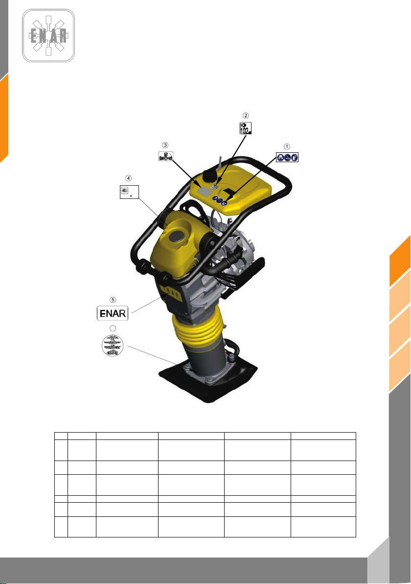
13
es
PH60 - PH70- PH80
Nº
REF.
DESCRIPCION
DESCRIPTION
DESIGNATION
BENENNUNG
ADHESIVO
SEGURIDAD
SAFETY
STICKER
ADHÉSIF
SÉCURITÉ
ADHESIVO 104 Dba
ADHESIF
104 Dba
ADHESIVO
DERECHO
4
RC6506
ANAGRAMA ENAR
ENAR STICKER
AUTOCOLANT ENAR
ENAR KLEBSTOFF
ADHESIVO
CARÁCTERÍSTICAS
CHARACTERISTICS
STICKER
AUTOCOLANT
CARACTÉRISTIQUES
MERKMALE
KLEBSTOFF
ADHESIVO
MUELLES
STICKER
SPRINGS
ADHÉSIF
RESSORTS
KLEBSTOFF
SPRUNGFEDER
L
WA
PHX0H
00000000
ENARCO, S.A.
C/ Burtina, 16
2012
50197 Zaragoza
(SPAIN)
6
7 PLACAS E INDICATIVOS/PLATES AND INDICATIVES/PLAQUES
ET INDICATEURS/PLATTEN UND KENNZEICHEN
1 107228
2 107402
3 107284
5
6 107225
PROTECCION
TUMBADO
PRECAUCION
PROTECTION
104 dBA STICKER
PLACE RIGHT SIDE
STICKER
PRECAUTION
PROTECTEUR
ADHÉSIF TOMBÉ À
DROIT
PRECAUTION
SCHUTZKLEBSTOFF
104 dBA KLEBSTOFF
RECHTGELIEGENER
PISONES
KLEBSTOFF
ACHTUNG
Page 15
es
14
PH60 - PH70 - PH80
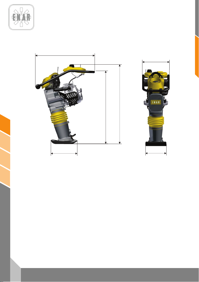
368
280
332
772
1038
953
8 ESPECIFICACIONES TÉCNICAS / TECHNICAL DATA /
SPECIFICATIONS TECHNIQUES / TECHNISCHE DATEN
PISONES
Page 16
15
es
PH60 - PH70- PH80
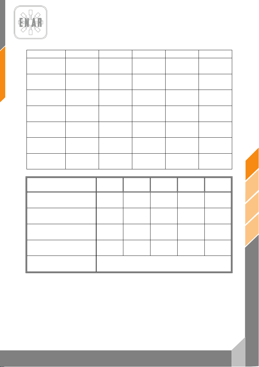
HONDA
GX100 DKR
ROBIN
ER12
HONDA
GX120 DKR
ROBIN
EH12 D
YANMAR
L48 AE
COMBUSTIBLE (L)
BRENNST OFF (L)
ACEITE MOTOR (L)
MOTORENÖL (L)
POTENC IA NOMINAL
NENNLEISTUNG
BUJÍA
ZÜNDKERZE
ENTREHIERRO
LUFTSPALT
R.P.M.
U-MN
RALE NTÍ
LEERLAUFD REHZAHL
PESO SIN COMBUSTIBLE (Kg)
GEWICHT (Kg)
ELEVACIÓN DEL PISÓN (mm)
SPRINGWEG (mm)
NUMERO DE GOLPES POR MINUTO
EINSCHLAGSFREQUENZ
MOTOR
MOTOR
LUBRICANTE MÁQUINA (L)
MASCHINENOEL (L)
FUEL (L)
COMBUSTIBLE (L)
SIN PLOMO (2.7) SIN PLOMO (2.7) SIN PLOMO (2,7) SIN PLOMO (2,7) GAS-OIL (2,7)
ENGINE OIL (L)
HUILE MOTEUR (L)
NOMINAL POWER
PUISSANCE NOMINALE
SPARK PLUG
BOUGIE
GAP
ENTREFER
R.P.M.
TR-MN
IDLING
RÉGIME RALENTI
SAE 10W/40 (0,6) SAE 10W/40 (0,4) SAE 10W /40 (0,3) SAE 10W/40 (0,4) SAE 10W/40 (0,8)
3 kW (4 HP) 3 kW (4 HP) 3 kW (4 HP) 2,6 kW (3,5 HP) 3,1 kW (4,1 HP)
NGK CR5HSB
DENSO U16FSR-UB
0,6 mm - 0,7 mm 0,6 mm - 0,7 mm 0,7 mm - 0,8 mm 0,6 mm – 0,7 mm
4000 rpm ± 50 4000 rpm ± 50 3500 rpm ± 50 3600 rpm ± 50 3600 rpm ± 50
1700 ±150 r.p.m. 1700 ±150 r.p.m. 1500 ±150 r.p.m. 1600 ±150 r.p.m. 1500 ±150 r.p.m.
NGK CR5HSB
DENSO U16FSR-UB
NGK BP4ES
DENSO W14EP -U
NGK B6ES
CHAMPION N4C
----
----
ESPECIFICACIONES PH60H PH60R PH70H PH70R PH80YD
WEIGHT WITHOUT COMBUSTIBLE (Kg)
POIDS SANS COMBUSTIBLE (Kg)
IMPACT COURSE HEIGHT (mm)
PARCOURS DE FRAPPE (mm)
NUMBER OF BLOWS BY MINUTE
FREQUENCE D’IMPACTS PAR MINUTE
ENGINE
MOTEUR
MACHINE OIL (L)
HUILE POUR MACHINE (L)
68 68 72 72 80
60 65 70 70 70
700 700 700 700 700
HONDA
GX100U
ROBIN
ER12
SAE 30 / ISO 100 (1.8 L.)
ROBIN
GX120U
ROBIN
EH12D
YANMAR
L48AE
PISONES
Page 17
es
16
PH60 - PH70 - PH80
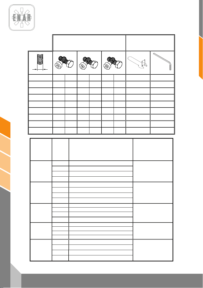
PAR DE APRIETE
TORQUE
COUPLE
DREHMOMENT
TAMAÑ O DE LLAVE
SPANNER SIZE
DIMENSION DE LA CLEF
GRÖSSE VON DEM
SCHRAUBERSCHLÜSSEL
8.8 10.9
12.9
MÉTRICA
Ft.Lb.
Nm
Ft.Lb.
Nm
Ft.Lb.
Nm
mm
mm
M4
*26
2.9
*36
4.1
*43
4.9 7 3
M5
*53
6.0 6 8.5 7 10 8 4
M6
7
10
10
14
13
17
10
5
M8
18
25
26
35
30
41
13
6
M10
36
49
51
69
61
83
17
8
M12
63
86
88
120
107
145
19
10
M14
99
135
140
190
169
230
22
12
M16
155
210
217
295
262
355
24
14
* = In.Lb. 1 Ft.Lb. = 1.357 Nm 1 Inch = 25.4 mm
TIPO
TYPE
TYPE
TYP
COLOR
COLOR
COLEUR
FARBE
USO
USE
USAGE
GEBRAUCH
Nº PIEZA/TAMAÑO
PARTNUMBER/SIZE
Nº PIÈCE/DIMENSION
TEILNUMMER/GRÄSSE
Morado
Resistencia baja, para fijar roscas menores a M36.Resiste
desde -54º a 149ºC.
Purple
Low strength, for locking threads smaller than M36.Temp.
Range –54º to 149ºC.
Violette
Peu de resistence pour fixer des filets plus petits que la M36.
Elle resiste de –54º jusqu’à 149ºC.
Loctite 222
Hernon 420
Omnifit 1150 (50M)
Dunkelviolett
Niedrieger widerstandskraft, um Gewinde kleiner als M36 zu
befestigen. Das widersteht von –54º bis 149ºC.
124151 – 10 ml
Azul
Resistencia media, para fijar roscas mayores a M36.Resiste
desde -54º a 149º C.
Blue
Medium strength, for locking threads larger than M36.Temp.
Range –54º to 149ºC
Bleue
Resistence moyenne pour fixer des filets jusqu’â M36. Elle
resiste de –54º jusqu’â 149ºC.
Loctite 243
Hernon 423
Omnifit 1350 (100M)
Blau
Medium widerstandskraft, um grösser als M36 Gewinde zu
befestigen. Das widersteht von 54º bis 149ºC.
124152 – 0.5 ml
124155 – 50ml
Blanco Sellador de tuberías con Teflón. Resiste desde -54º a 149º C.
White Pipe sealant with Teflon. Temp. Range –54º to 149º C.
Blanque
Colle de tuyanterie avec teflon. Elle resiste de –54º jusqu’à
149ºC.
Loctite 592
Hernon 920
Omnifit 790
Weis
Klebstoff mit teflon für Rohrleitungen. Das widerstehr von –54º
bis 149ºC.
6 ml
50 ml
Transparente Adhesivo estructural para metal. Resiste desde -54º a 82º C.
Clear Instant adhesive for metal. Temp. Range –54º to 82º C.
Transparente Colle instantanée pour metal. Elle resiste de –54º jusqu’à 149ºC
Loctite 495
Deurchsichtig Sofortiger klebstoff für metal. Das widersteht von –54º bis 82ºC
124156 – 1 oz.
Verde
Producto anaeróbico de retención de alta resistencia, tolerante
al aceite.
Green
High resistant product, wich doesn´t need air to react and bears
the oil.
Verte
Producte anaérobie de rétention d’haute resistence, tolérant au
huile.
Loctite 601
Grün
Stoff von grösser widerstandskraft, der ohne sauerstoff reagiert
und das öl zulässt.
124154 – 6 oz.
PISONES
Page 18
CERTIFICADO DE CONFORMIDAD
CONFORMITY CERTIFICATE ~ CERTIFICAT DE CONFORMITÉ
INSTEMMING VERKLARING ~ KONFORMITÄTS BESCHEINIGUNG
KONFORMITETS BEVIS ~ CERTIFICATO DE CONFORMIDADE ~ CERTIFICATO DI CONFORMITA'
ATITIKTIES DEKLARACIJA ~ CERTYFIKAT ZGODNOŚCI ~ СЕРТИФИКАТ СООТВЕТСТВИЯ
CERTIFICAT DE CONFORMITATE~ СЕРТИФИКАТ ЗА СЪОТВЕТСТВИЕ
certifica que la máquina especificada
hereby certify that the equipment specified bellow ~ atteste que le equipment
verklaart hierbij dat onderstaand gespecificeerde ~ bescheinigt, da
bekræfter, at følgende maskine ~ certifica que o equipamento specificaçao
certifica che la macchina specificata ~ šiuo sertifikatu patvirtina, kad žemiau nurodytas prietaisas, t.y.
Zaświadcza, że wyszczególniona maszyna ~ Подтверждает, что нижеописанная машина
Certifica si declara ca echipamentul mentionat mai jos~ Потвърждаваме, че оборудването, описано по-долу
TIPO DE MAQUINA..................................................................................... Pison Compactador
TYPE~TYPE~TYPE~TYP~TYPE~TIPO~TIPO~TIPAS~TYP~ТИП~TIP~ТИП Tamping Rammer / pilonneuse / Stampfer
MODELO.....................................................................................................PH
MODEL~MODÈLE~MODEL~MODEL~MODEL~MODELO
MODELLO MODELIS~MODEL~МОДЕЛЬ~MODEL~МОДЕЛ
CODIGO...................................................................................................... PH60*, PH70*, PH80*
CODE~CODE~CODE~CODE~CODE~CODIGO~CODICE~KODAS~KOD
КОД~ COD ~ КОД
in overeenstemming met de voldenge voorschriften gefabriceerd is ~ in übereinstimmung mit folgenden richtlinien hergestellt worden ist
Potencia acústica medida (LWA)
Gemessene Schalleistung (LWA)
Puissance acoustique mesurée (LWA)
Measured acoustic power (LWA)
Potência acústica medida (LWA)
Moc akustyczna srednia (LWA)
RESPONSABLE DOCUMENTACIÓN TÉCNICA………. Jesus Tabuenca (ENARCO, S.A. Burtina, 16, 50197 Zaragoza
Technical documentation responsible ~ Responsable of the Documentation Technnique ~ zuständigen technishen Dokumentation
Zaragoza, 01.10.2011
MANUFACTURER:
ENARCO, S.A.
C/Burtina 16
Plat. Logística PLAZA
50197 ZARAGOZA
ha sido fabricada de acuerdo con las siguientes normas
has been manufactured according to the following standards ~ est produit conforme aux dispositions des directives ci-apres
er blevet fremstillet i overenstemmelse med følgende retningslinier ~ é fabricado conforme as seguintes normas
è stata fabbricata secondo le norme vigenti ~ buvo pagamintas laikantis toliau išvardintų standartų
została wyprodukowana zgodnie z następującymi normami ~ Произведена в соответствии со следующими нормами
este fabricat cu respectarea urmatoarelor standarde ~ е производено в съответствие със следните стандарти
2006/42/CE, 2000/14/CE, 2005/88/CE
104
dB (A)
SPAIN
e-mail:
Web:
Tfno.
ENARCO,S.A.
EN 500/1, EN 500/4
Potencia acústica garantizada (LWA)
Garantierte Schalleistung (LWA)
Puissance acoustique garantie (LWA)
Guaranteed acoustic power (LWA)
Potência acústica garantida (LWA)
Moc akustyczna gwarantowana (LWA)
(34) 976 464 090
das Baugerät
β
106
dB (A)
Jose Luis Del Prim
General Manager
ENARCO,S.A.
ENARCO, S.A.
Page 19
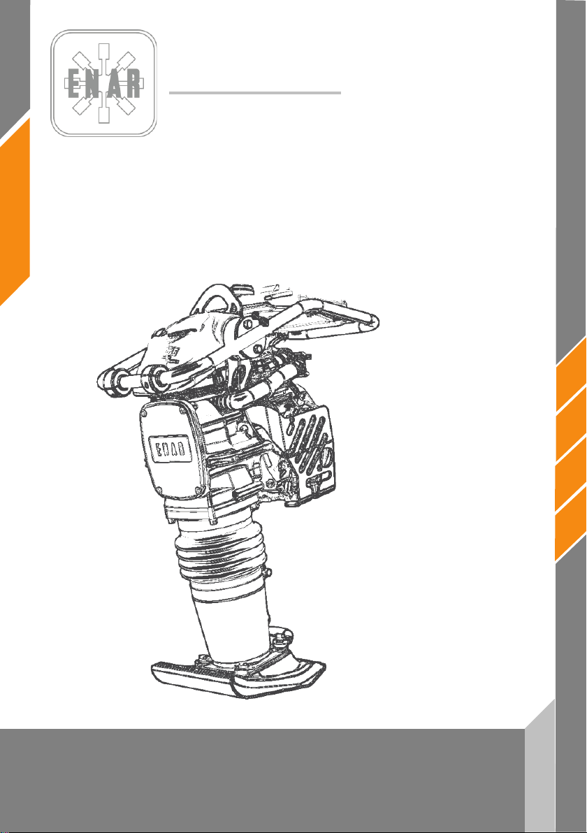
ENARCO, S.A.
en
TAMPING RAMMERS
PH60 - PH70 - PH80
Instruction manual
Page 20

1
en
PH60, PH70, PH80
CONTENTS
1 PREFACE 2
2 SAFETY INFORMATION 3
2.1 SAFETY DURING THE OPERATION OF THE MACHINE 3
2.2 SAFETY DURING OPERATION OF THE ENGINE 3
2.3 SAFETY DURING SERVICE 4
3 WHICH MACHINE IS THE MOST SUITABLE FOR EACH APPLICATION? 4
4 SOUND AND VIBRATION MEASUREMENTS 5
5 STARTING, OPERATION AND MAINTENANCE OF THE MACHINERY 5
5.1 BEFORE STARTING WORK 5
5.2 STARTING UP THE MACHINE 5
5.3 OPERATING THE MACHINE 6
5.4 STOPPING THE MACHINE 6
5.5 MAINTENANCE SERVICE AND STORAGE 7
5.6 LOCALIZING AND REPAIRING FAULTS 9
6 IN CASE OF FAILURE 12
6.1 INTRUCTIONS FOR ORDERING PARTS 12
6.2 INTRUCTIONS FOR REQUESTING GUARANTEES 12
7 PLACAS E INDICATIVOS/PLATES AND INDICATIVES/PLAQUES ET INDICATEURS/PLATTEN
UND KENNZEICHEN 13
8 ESPECIFICACIONES TÉCNICAS / TECHNICAL DATA / SPECIFICATIONS TECHNIQUES /
TECHNISCHE DATEN 14
TAMPING RAMMERS
Page 21

en
2
PH60, PH70, PH80
1 PREFACE
We would like to thank our customers for the trust placed in the ENAR brand.
It is important to read this manual to gain a full understanding of the characteristics and
functions of the compactor. Before commencing work with this machine, or performing maintenance
tasks on it, read, digest and observe all the safety instructions included in this manual.
In the event of this manual becoming lost or a further copy required, this can be ordered from
ENARCO or printed out direct from the ENARCO website:
Following the correct procedures for maintenance will guarantee the long life and excellent
performance of this equipment.
Although this manual provides certain specifications for the motor, we recommend consulting
the instruction manual for the motor for information on maintenance and repairs.
If information concerning the operation or maintenance of this machine is required, please
contact the ENARCO customer service by telephone or fax, or by sending an email to
or through our website in the section entitled
.
Servicio ENAR.
http://www.enar.es.
TAMPING RAMMERS
Page 22

3
en
PH60, PH70, PH80
!
!
2 SAFETY INFORMATION
2.1 SAFETY DURING THE OPERATION OF THE MACHINE
Improper use or maintenance of the equipment may lead to hazardous situations. Read and
digest the instructions in this section before starting work with this machine. Machine operators
should ensure that they know how to work the equipment safely. All queries should be dealt
with by personnel familiar with the machine or else by contacting ENARCO directly.
• The motor gets very hot during operation: leave it to cool down before touching it.
• Never leave the machine unattended during operation.
• Operators should use protective clothing and ear muffs.
• Close off entry to the worksite for all unauthorised personnel.
• Make sure you know how to disconnect the machine before starting up the motor in case you
get into difficulties.
• Make sure the machine has stopped before any attempt is made to move it.
• Do not attempt to lift the equipment unaided. Ask for help or use a lifting machine, taking hold
of the equipment by the lifting handle incorporated in the assemblysurrounding the compaction
plate.
• Do not use the equipment if you are not in good physical shape.
• Store the equipment properly in a clean, dry place whenever it is not going to be used. Fuels
and other consumables should be kept in marked containers in accordance with the
manufacturer’s instructions. All current legislation concerning the storage site should also be
complied with.
2.2 SAFETY DURING OPERATION OF THE ENGINE
• Do not operate the machine inside a building or closed area without adequate ventilation.
• Before filling the fuel tank, stop the motor and leave it to cool down for a few minutes.
• Smoking is prohibited while the machine is in operation, or being refueled.
• Do not refill the tank near an open flame and remember to always refuel in an area that is well
• If the fuel tank is not airtight, it should be replaced immediately, since it could lead to
• If any fuel is spilt while refueling, spread sand over the area. Change your clothes if any fuel is
• Make sure that the fuel tank is closed properly after refueling.
• Check that there are no cracks or leaks in the pipes or fuel tank.
TAMPING RAMMERS
Owing to their high degree of inflammability, fuels are particularly dangerous. Improper use can
cause serious damage to personnel and materials. Always observe the following safety
regulations:
Failure to comply with this regulation may lead to intoxication from carbon monoxide with loss
of consciousness, and even death.
ventilated.
explosions.
spilt on them.
Page 23
en
4
PH60, PH70, PH80
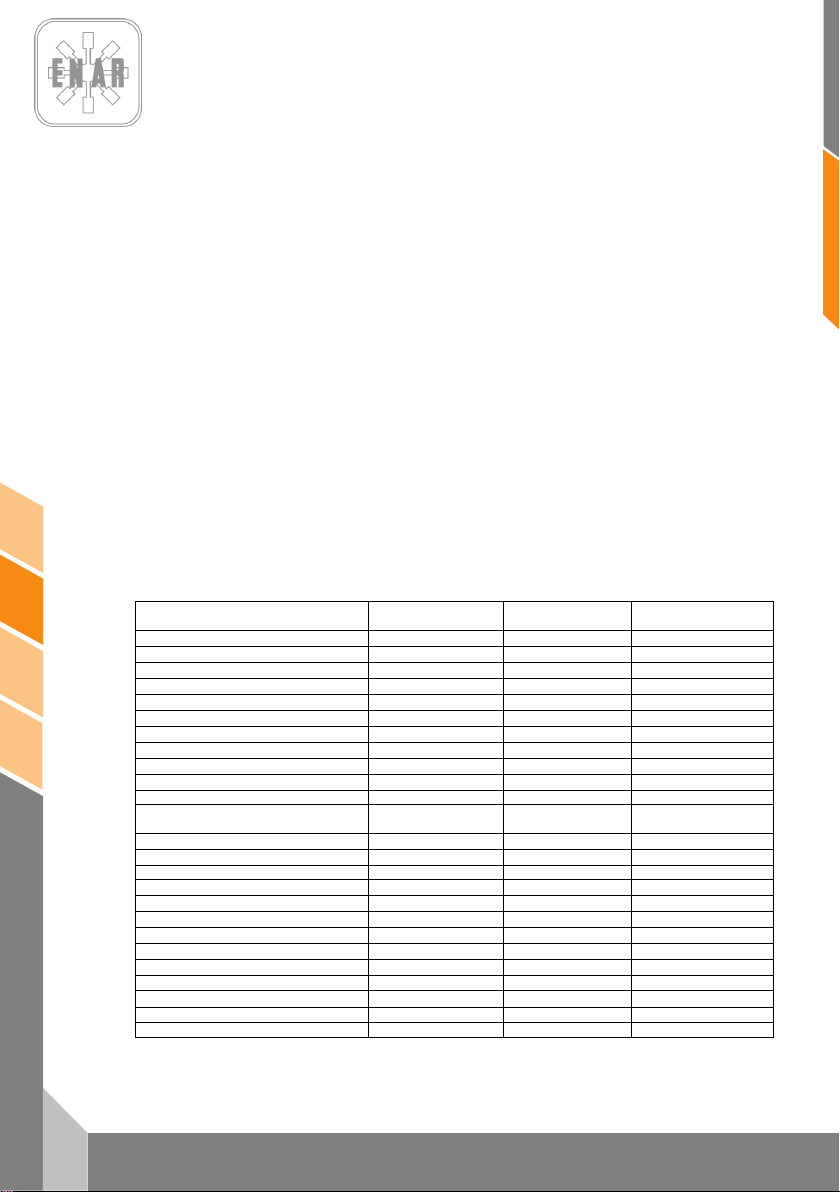
MODEL
APPLICATION
Reversible plates
Non-reversible
plates
Tamping rammers
Patching areas
#
Building foundations
+
Paths and footways
#
Tennis courts and sports areas
#
Soil preparation
+ # #
Final support for bridge and ramps
+ + #
Railway junctions
+ + #
Interlocking cement blocks
# +
Construction of mains
+ # +
Construction of drainage
+ +
Compaction of ditches.
+ +
Reparation of damage caused by
broken piping, cables, etc.
Work around piping, cables, drainage,
# # +
Filling with rocks
Gravel
+ + +
Sand or volcanic material
+ + #
Mixed grounds
+ # +
Mud +
+
Clay + + Layer thickness 0 – 25 cm
+ + +
Layer thickness 20 – 40 cm
+ +
Hot mortar
# + #
Cold mortar
# + #
Subgrade 40 – 100 mm
+ # +
Layer of boulders 25 – 60 mm
# +
2.3 SAFETY DURING SERVICE
• Do not clean or inspect the equipment during operation.
• Do not start the motor up with the cylinder flooded or if the spark plug in the petrol motors has
been removed.
• Do not inspect the igniter plug to see if it is sparking correctly if the cylinder is flooded with
petrol or in the presence of any petrol fumes.
• Do not use dissolvents or fuels to clean the equipment, particularly in closed spaces.
• Maintain the area around the silencer clear of inflammable materials.
• Before servicing petrol-driven machines, remove the spark plug to guard against the motor
starting up accidentally.
• It is not permitted to use the equipment in explosive environments. The fuel tank should be
shut tight. When being transported over long distances, it is highly recommended that the fuel
tank be emptied beforehand.
• The transport accessory has not been designed for standing the compaction plate on it and
should only be used to move the equipment.
3 WHICH MACHINE IS THE MOST SUITABLE FOR EACH
APPLICATION?
# +
# Can be used + Recommended
TAMPING RAMMERS
Page 24
60,
70, P
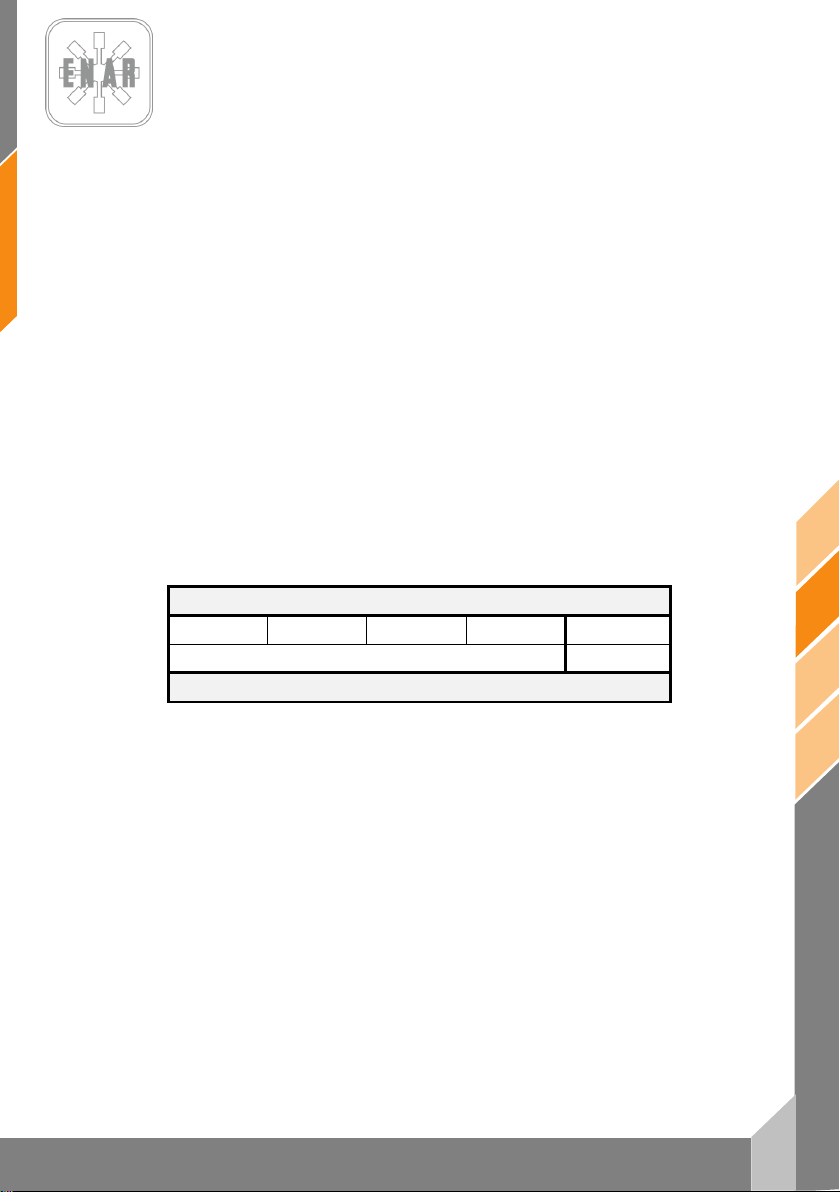
4 SOUND AND VIBRATION MEASUREMENTS
- Level of acoustic power according to EN 500-4: LWA 106 dB(A)
- Level of acoustic pressure according to EN 500-4: L
- Weighted real value of axial acceleration according to EN 500-4 : Ahv
96 dB(A)
pA
6,8 m/s
2
5 STARTING, OPERATION AND MAINTENANCE OF THE
MACHINERY
5.1 BEFORE STARTING WORK
5.1.1. The mechanisms of this machine are lubricated by means of an oil bath. Check the oil
level using the visor situated at the rear beneath the bellow. If oil cannot be seen through the visor,
add oil until half the visor is covered.
5.1.2. Fill the fuel tank with the appropriate type of fuel for the engine your machine is provided
with, according to the table below:
ENGINE TYPE
HONDA GX120 HONDA GX100 ROBIN ER12 ROBIN EH12 YANMAR L48
When filling the tank, be sure to filter the fuel with a strainer. Do not forget to replace the fuelling cap
and close it. Failure to do this is dangerous, as the vibration of the machine may cause spillages of
fuel that then ignite and burn.
5.1.3 Be sure to check the tension of every bolt, nut or threaded area. A screw that has come
loose due to vibration may unexpectedly cause a serious problem. Make sure that all screws are
tightened.
5.1.4. Remove all dirt and dust. Pay special attention to cleaning the area adjacent to the
5.2 STARTING UP THE MACHINE
5.2.1. Open the fuel tap by moving the air regulator lever downwards, and put the choke valve
lever in the half-open position. To start the engine cold, move the air regulator lever to the closed
position. When the engine is hot, the air regulator should be half-open or completely open. If it
proves difficult to start the engine, make sure that the air regulator lever is half-open to prevent the
carburettor from flooding due to excess fuel.
5.2.2. When pulling the starter rope, do not apply full pressure for the whole length, as this may
damage the spring. Do not suddenly release the rope in order to repeat the process once the engine
has started. Hold on to the rope, and slowly release until it has fully returned to position.
starter and the leg.
TAMPING RAMMERS
UNLEAD PETROL GAS-OIL A
TYPE OF FUEL
PH
PH
en
5
H80
Page 25

en
6
PH60, PH70, PH80
5.3 OPERATING THE MACHINE
5.3.1. After starting the engine, gradually re-open the air regulator lever completely. Allow the
engine to warm up at minimum velocity for a period of 3 to 5 minutes. This procedure of warming up
the engine at a minimum revolution level is particularly important during the cold period. While the
engine is warming up, carry out a general revision of the machine to make sure that there are no
anomalies.
5.3.2. The piston starts to operate when the accelerator lever is turned with a rapid movement a
quarter of a revolution. If the lever is moved slowly, the action of the rammer will be irregular,
possibly causing damage to the clutch, the spring and the leg.
5.3.3. After the machine has started to operate, adjust the movement of the vibration in such a
way that it conforms to the particular condition of the ground, using the accelerator lever slightly as a
control. This rammer has been designed in such a manner that when the engine works at a velocity
of between 3,600 and 4,000 r.p.m., its leg hits the surface of the ground at a rate of 600 to 700 times
per minute, thus ensuring the greatest efficiency of performance. An unnecessary increase in the
velocity of the engine does not produce any increase in the force of compaction. Instead, the
resulting resonance causes a reduction in the compaction force, damaging the machine.
5.3.4. In cold weather, as the oil in the machine is viscous, the resistance in the alternating part
is greater, producing a somewhat irregular movement in the compacting rammer. For this reason, it
is recommended that the machine should be run for a while before starting work to warm it up,
moving the accelerator lever repeatedly between the positions 0 and ¼ turn.
5.3.5. The surface of the leg in contact with the ground is covered with a thermally treated
metallic plate. Nonetheless, for the compaction of boulder it is advisable to use a filling of fine
material such as sand so that the rear end of the leg's plane surface makes contact with the ground.
5.3.6. The compacting rammer has been designed to advance as it vibrates. To speed up the
rate of advance, raise the machine by pulling it slightly in a backwards direction, in such a way that
the rear end of the leg's plane surface makes contact with the ground.
5.4 STOPPING THE MACHINE
5.4.1. To stop work rapidly shift the accelerator lever from position ¼ to 0, the inverse of the
movement for starting the machine.
5.4.2. Before stopping the engine, leave it ticking over for two to three minutes and then press
the stop button until the engine stops completely.
5.4.3. Close the fuel tap by putting the lever in a horizontal position.
TAMPING RAMMERS
Page 26
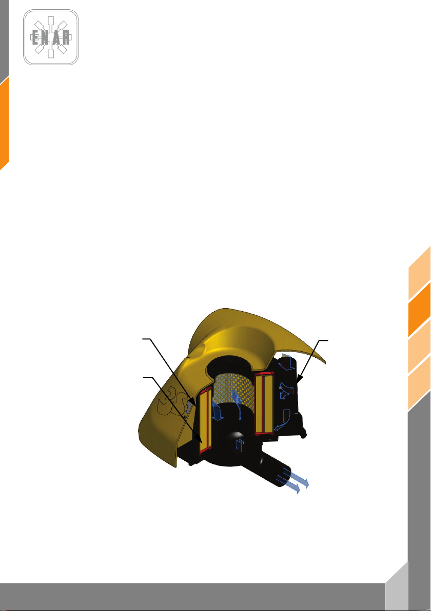
7
en
PH60, PH70, PH80
2ª STAGE
1ª STAGE
3ª STAGE
5.5 MAINTENANCE SERVICE AND STORAGE
5.5.1. Before undertaking any maintenance service on the compacting rammer, STOP THE
5.5.2. Daily maintenance service:
Remove all dirt, dust or oil entirely from the machine. Check the air filter, cleaning it as necessary.
Tighten up any areas where oil has leaked, and make sure that all other areas are tightened as
necessary.
5.5.3. Weekly maintenance service (every 50 hours):
Remove the cap of the air filter and clean the internal element using a neutral cleansing solution.
After drying, apply a fuel composed of a mixture of petrol and oil (if possible, utilize the fuel in use),
and shake well. Then, gently squeeze the primary external element (sponge) and place it on the
secondary internal element to cover it.
In the sparking plug, adjust the distance between electrodes to a value of between 0.7 and 0.8 mm.
Remove the oil cap (situated above the oil-level visor), and put the machine in a horizontal position
in such a way that the oil hole serves to drain off the used oil, placing the machine with the hole
downwards in order to drain the oil completely.
Place the machine upright again, and use the same hole to pour in new oil, until the correct level can
be seen in the visor.
The first change of oil should be made after 50 hours in operation, from the second time onwards
every 300 hours in operation.
5.5.4. Maintenance service fortnightly (100 hours) or with signal from air filter sensor (if
ENGINE COMPLETELY.
it’s present):
TAMPING RAMMERS
FILTERING STAGES
Page 27
en
8
PH60, PH70, PH80
3
4
1
2
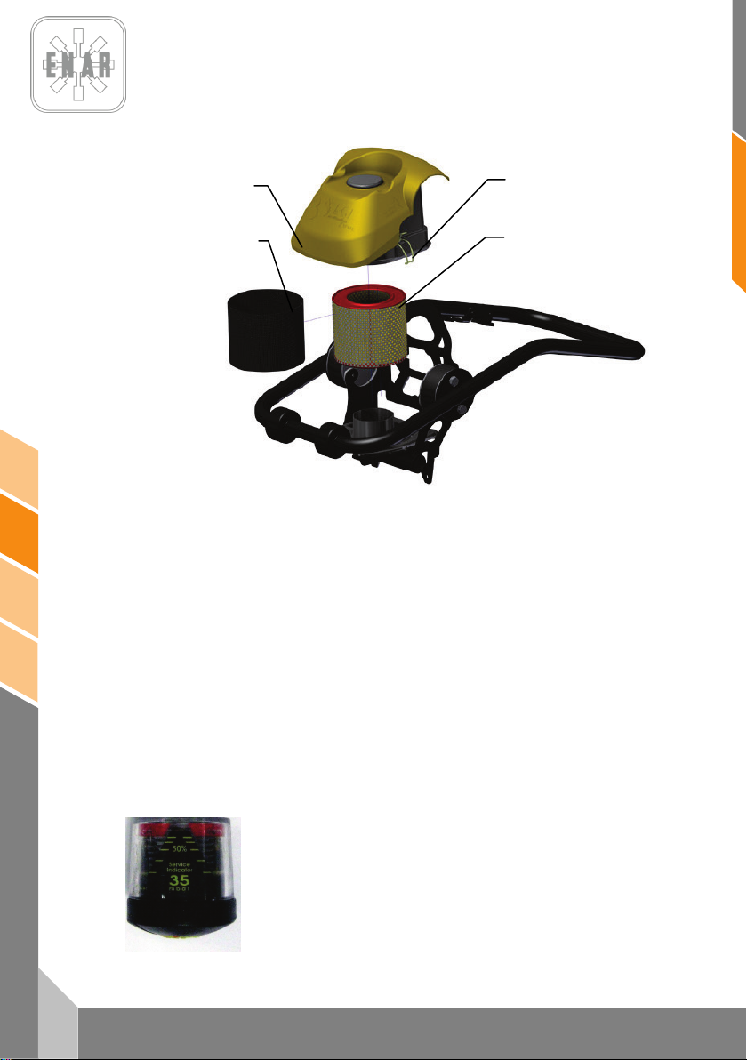
Release the retaining clips (2) Remove the air filter cover (1). Remove the second (3, sponge) and
third stages of filtration (4, cartridge). Shake the third stage and blow it from inside to outside. Clean
the second stage filter with a neutral cleaning solution. After drying, apply a mix of gasoline and oil,
and shake it vigorously. Then, lightly squeeze the external primary element (sponge) and mount it on
the third stage, mount the assembly in the filter lower housing, place and close the upper housing
with mounting clips.
5.5.5. Monthly maintenance service (every 300 hours):
Clean the inside of the fuel tank. Carefully clean every part of the machine, and again make sure all
the bolts and nuts are tightened up as necessary.
5.5.6. Correct storage:
For a prolonged period of storage after a particular job has been terminated, completely drain the
fuel from the interior of the tank, the fuel tube and the carburettor.
Remove the sparking plug, pour a few drops of oil into the cylinder, and by hand get the engine to
make a few revolutions in such a way that the oil reaches the whole area. As for the exterior, clean it
with a cloth dampened with oil.
To store the machine, keep it under cover in a location free from humidity and dust and out of direct
sunlight.
5.5.7. Air filter sensor maintenance:
If air filter sensor is present, as air filter dirties, the yellow body in sensor
reaches the red zone indicating need for service. Do filter maintenance as
indicated in point 5.5.4 and reset the sensor by pressing the yellow button.
TAMPING RAMMERS
Page 28

9
en
PH60, PH70, PH80
5.5.8. Tachometer operation.
When the engine is shut off the display shows total run time, this time
cannot be reset. When engine is started the display shows revolutions
per minute.
To view partial job time press "SELECT". To reset job time push and
hold "SELECT" button until display shows “RESET” and hours
accumulated on the current job, When you release the button the
With diesel engine:
SVC2 service alarm: after 50 hours working the tachometer will show SVC2 alarm. Perform
prescribed maintenance. To reset press "RESET" three times and hold RESET until display shows
“RESET”.
SVC Service alarm: After 250 hours tachometer will show alarm SVC. Perform prescribed
maintenance. To reset press "RESET" twice and hold RESET until display shows “RESET”.
counter will reset to 0.
5.6 LOCALIZING AND REPAIRING FAULTS
PETROL ENGINE
Does not start:
- There is fuel, but the sparking plug does not produce a spark
• There is electricity in the high-tension cable
Sparking plug flecked
Carbon deposit in the sparking plug
Short-circuit due to insufficient insulation of the sparking plug
Incorrect separation between electrodes
• There is no electricity in the high-tension cable
Switch of detention button short-circuited
Ignition coil defective
Insulation of condenser deficient or short-circuited
Ignition coil broken or short-circuited
• Compression satisfactory
Incorrect fuel
Water or dust has entered
Defective air filter
- There is fuel, and the sparking plug does produce a spark
• Compression insufficient
Inlet valve or exhaust valve stuck or defective
Piston ring or cylinder worn out
Cylinder head or sparking plug incorrectly fitted
Cylinder head joint or sparking plug joint defective
• The clutch is blocked, causing vibrator to rotate when attempt is made to
start
• There is no fuel in the carburettor
Fuel tank is empty
Fuel tap is not correctly open
Fuel filter is blocked
Air ventilation opening in tank lid is blocked
Air retention in tube
Inlet valve of carburettor is stuck
TAMPING RAMMERS
Page 29

en
10
PH60, PH70, PH80
No power:
- Insufficient power
• Normal compression and no visible defect in ignition
Air filter defective
Carbon deposit in cylinder
Incorrect fuel level in carburettor
• Insufficient compression
(See “Compression insufficient” above)
• Compression is correct, but ignition is defective
There is water in the fuel
Sparking plug is dirty
Ignition coil is defective
Ignition coil keeps short-circuiting
• Vibrator is full of excess oil
- Engine overheated
• Carbon deposit in fuel chamber or exhaust vent
• Incorrect heat-producing capacity in sparking plug
• Cooling fins are dirty
- Rotation velocity fluctuates
• Regulator incorrectly set
• Regulator spring faulty
• Deficient fuel flow
Starter functioning defectively
DIESEL ENGINE (AIR COOLED)
Problems with starting:
A.- Insufficient compression
• Air entering tube suction system
- Rotating part clogged with dust
- Helical spring faulty
• No compression
Suction valve or exhaust valve defective
Decompression system incorrectly set
• There is little or virtually no compression
Contact of valve seating is defective
Piston ring is eroded
Cylinder is worn out
Surface of cylinder fitting and cylinder head defective
Seating of injector is loose
B.- Fuel injection in the combustion chamber is not functioning properly
• There is little or no flow of fuel
Air ventilation opening in tank lid is blocked
Pass of fuel filter is obstructed and the filter is blocked
Tap of fuel filter is closed
Air retention in tube (particularly when the tank is empty)
TAMPING RAMMERS
Page 30

11
en
PH60, PH70, PH80
Insufficient power output. Insufficient compression:
TAMPING RAMMERS
• There is no fuel injection in the combustion chamber
Cylinder of injection pump or piston is stuck
Injector blocked
Injector needle is stuck
• Fuel tank is empty
• Water or dust has entered
C.- System of fuel and compression etc. as normal, yet nonetheless machine does not
start
• Starting velocity is not reached
Incorrect starting procedure
High viscosity or excessi ve contamination of the oil in the engine
Air retention in tube
• Engine overheated and exhaust dirty
Cooling f ins are dirty
W ater in fuel filter
Carbon deposit in combustion chamber or exhaust vent
Fume level incorrectly set
Overloading
Injection feed incorrectly set
Injector blocked
• There are fluctuations in velocity
Faulty contact b etween regulator fork and sleeve
Faulty regulator spring
Plate of rocker arm and other sliding parts are worn out or functioning imperfectly
• The engine does not increase its velocity as it should
Incorrect valve synchronization
Exhaust vent or silencer blocked
Overloading
• Ignition defective accompanied by blank exhaust
Piston, cyl inder, ring worn out
Injector blocked
Upper and lower piston rings fitted the wrong way round
Inject ion feed incorrectly set.
Incorrect valve synchronization
Injection pump joint is loose
• High fuel consumption (exhaust appears dark)
Leak in fuel piping
Element of a ir filter is blocked
Fuel defective due to impurities
Overloading
• Sliding part is excessively worn out, or piston ring is stuck
Defective oil is being used
Regular replacement of oil is being neglected
Element of air filter is defective or dirty
• Machine stops suddenly, making a strange noise
Seize-up or damage of piston or connecting rod
• Lubricating oil diluted, increasing its volume
Body of injection pump piston is worn out
• The engine does not stop even when the fuel supply is broken off
(or it causes an overdrive)
Excess o il
Regulator system incorrectly installed
Frame of injection pump is out of place
Page 31

en
12
PH60, PH70, PH80
OPERATION OF THE MACHINE
Transition velocity is slow and vibration weak.
Movement of machine is askew.
• The regulator does not open to the correct velocity of engine (see page 10)
• Insufficient power of engine
• Clutch slips
• Excess of oil on vibrator
• Internal parts of vibrator are defective
Moves forwards or backwards, but cannot switch
• Incorrect fitting of advance or return cable
• Vibrator is jammed
• Parts of motion-direction selector are defective
• Clutch lever incorrectly fitted
Neither moves forwards nor backwards
• Clutch slips
• Vibrator is jammed
• If there is vibration but no movement, it could be that the vibrator is on a moist
or slippery surface. Try on the appropriate surface.
6 IN CASE OF FAILURE
6.1 INTRUCTIONS FOR ORDERING PARTS
1. In all orders placed for parts, THE CODE NO. GIVEN IN THE LIST OF PARTS SHOULD BE
INCLUDED FOR THE PART CONCERNED. It is advisable to include the MACHINE’S SERIAL
NUMBER.
2. The specifications plate with the serial numbers and MODEL are on the top of the engine
plate.
3. Please supply the correct instructions for transport, including the preferred route, address and
complete name of the consignee.
4. Do not return parts to the factory unless you have been given written permission to do so. All
authorized items should be returned carriage paid.
6.2 INTRUCTIONS FOR REQUESTING GUARANTEES
1. The guarantee is valid for one year from the date the machine was purchased. The guarantee
covers the parts with manufacturing faults.
o In no case will the guarantee cover a fault caused by improper use of the equipment.
2. In all requests for guarantees, THE MACHINE SHOULD BE SENT TO ENARCO, S.A. OR AN
AUTHORIZED WORKSHOP, always indicating the complete name and address of the
consignee.
3. The Technical Department (S.A.T.) will notify you f the guarantee has been accepted and, if
requested, can also send out a technical report.
4. No piece of equipment will be covered by guarantee if it has been manipulated previously by
personnel not connected to ENARCO, S.A.
NOTA: ENARCO, S.A., reserves the right to modify any part of this manual without prior notice.
TAMPING RAMMERS
Page 32
13
en
PH60, PH70, PH80
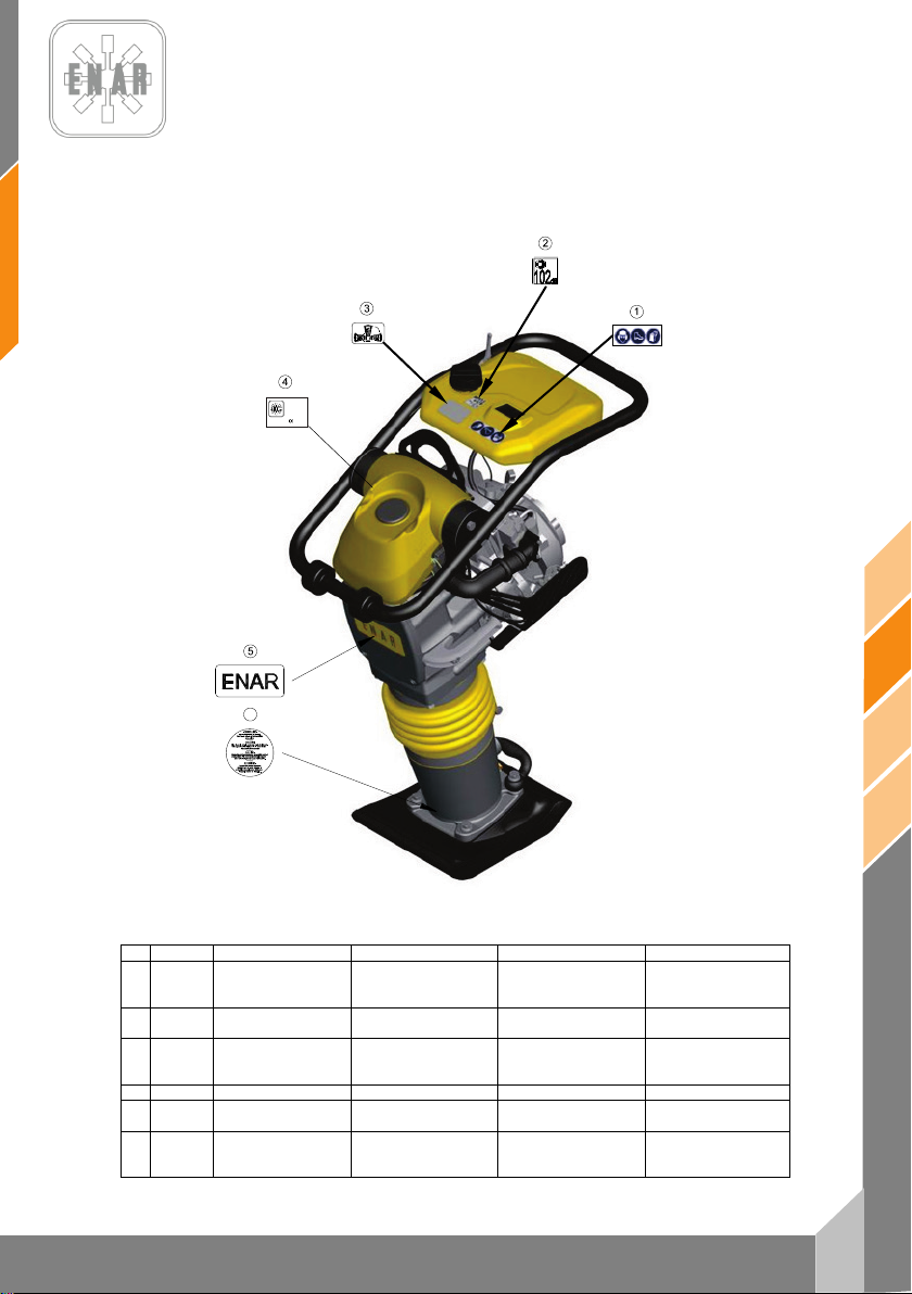
Nº
REF.
DESCRIPCION
DESCRIPTION
DESIGNATION
BENENNUNG
ADHESIVO
SEGURIDAD
SAFETY
STICKER
ADHÉSIF
SÉCURITÉ
ADHESIVO 104 Dba
ADHESIF
104 Dba
ADHESIVO
DERECHO
4
RC6506
ANAGRAMA ENAR
ENAR STICKER
AUTOCOLANT ENAR
ENAR KLEBSTOFF
ADHESIVO
CARÁCTERÍSTICAS
CHARACTERISTICS
STICKER
AUTOCOLANT
CARACTÉRISTIQUES
MERKMALE
KLEBSTOFF
ADHESIVO
MUELLES
STICKER
SPRINGS
ADHÉSIF
RESSORTS
KLEBSTOFF
SPRUNGFEDER
L
WA
PHX0H
00000000
ENARCO, S.A.
C/ Burtina, 16
2012
50197 Zaragoza
(SPAIN)
6
7 PLACAS E INDICATIVOS/PLATES AND INDICATIVES/PLAQUES
ET INDICATEURS/PLATTEN UND KENNZEICHEN
1 107228
2 107402
3 107284
5
6 107225
PROTECCION
TUMBADO
PRECAUCION
PROTECTION
104 dBA STICKER
PLACE RIGHT SIDE
STICKER
PRECAUTION
PROTECTEUR
ADHÉSIF TOMBÉ À
DROIT
PRECAUTION
TAMPING RAMMERS
SCHUTZKLEBSTOFF
104 dBA KLEBSTOFF
RECHTGELIEGENER
KLEBSTOFF
ACHTUNG
Page 33
en
14
PH60, PH70, PH80
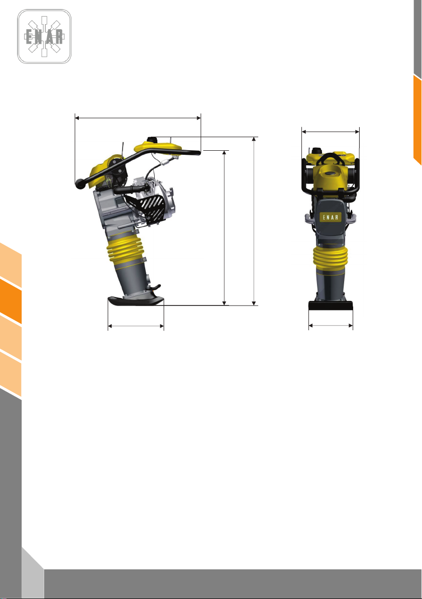
368
280
332
772
1038
953
8 ESPECIFICACIONES TÉCNICAS / TECHNICAL DATA /
SPECIFICATIONS TECHNIQUES / TECHNISCHE DATEN
TAMPING RAMMERS
Page 34
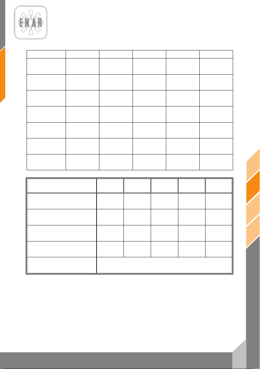
15
en
PH60, PH70, PH80
HONDA
GX100 DKR
ROBIN
ER12
HONDA
GX120 DKR
ROBIN
EH12 D
YANMAR
L48 AE
COMBUSTIBLE (L)
BRENNST OFF (L)
ACEITE MOTOR (L)
MOTORENÖL (L)
POTENC IA NOMINAL
NENNLEISTUNG
BUJÍA
ZÜNDKERZE
ENTREHIERRO
LUFTSPALT
R.P.M.
U-MN
RALE NTÍ
LEERLAUFD REHZAHL
PESO SIN COMBUSTIBLE (Kg)
GEWICHT (Kg)
ELEVACIÓN DEL PISÓN (mm)
SPRINGWEG (mm)
NUMERO DE GOLPES POR MINUTO
EINSCHLAGSFREQUENZ
MOTOR
MOTOR
LUBRICANTE MÁQUINA (L)
MASCHINENOEL (L)
FUEL (L)
COMBUSTIBLE (L)
SIN PLOMO (2.7) SIN PLOMO (2.7) SIN PLOMO (2,7) SIN PLOMO (2,7) GAS-OIL (2,7)
ENGINE OIL (L)
HUILE MOTEUR (L)
NOMINAL POWER
PUISSANCE NOMINALE
SPARK PLUG
BOUGIE
GAP
ENTREFER
R.P.M.
TR-MN
IDLING
RÉGIME RALENTI
SAE 10W/40 (0,6) SAE 10W/40 (0,4) SAE 10W /40 (0,3) SAE 10W/40 (0,4) SAE 10W/40 (0,8)
3 kW (4 HP) 3 kW (4 HP) 3 kW (4 HP) 2,6 kW (3,5 HP) 3,1 kW (4,1 HP)
NGK CR5HSB
DENSO U16FSR-UB
0,6 mm - 0,7 mm 0,6 mm - 0,7 mm 0,7 mm - 0,8 mm 0,6 mm – 0,7 mm
4000 rpm ± 50 4000 rpm ± 50 3500 rpm ± 50 3600 rpm ± 50 3600 rpm ± 50
1700 ±150 r.p.m. 1700 ±150 r.p.m. 1500 ±150 r.p.m. 1600 ±150 r.p.m. 1500 ±150 r.p.m.
NGK CR5HSB
DENSO U16FSR-UB
NGK BP4ES
DENSO W14EP -U
NGK B6ES
CHAMPION N4C
----
----
ESPECIFICACIONES PH60H PH60R PH70H PH70R PH80YD
WEIGHT WITHOUT COMBUSTIBLE (Kg)
POIDS SANS COMBUSTIBLE (Kg)
IMPACT COURSE HEIGHT (mm)
PARCOURS DE FRAPPE (mm)
NUMBER OF BLOWS BY MINUTE
FREQUENCE D’IMPACTS PAR MINUTE
ENGINE
MOTEUR
MACHINE OIL (L)
HUILE POUR MACHINE (L)
68 68 72 72 80
60 65 70 70 70
700 700 700 700 700
HONDA
GX100U
ROBIN
ER12
SAE 30 / ISO 100 (1.8 L.)
ROBIN
GX120U
ROBIN
EH12D
YANMAR
L48AE
TAMPING RAMMERS
Page 35
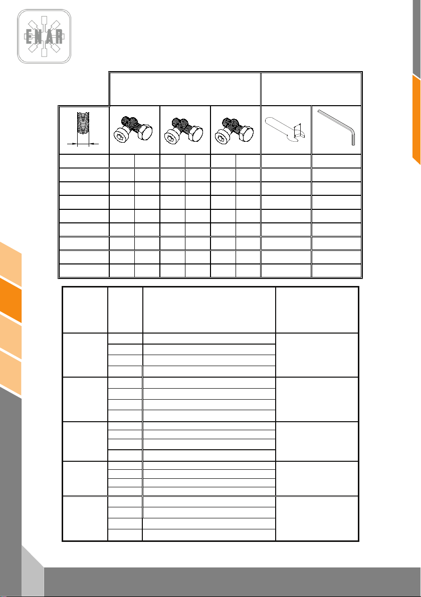
en
16
PH60, PH70, PH80
PAR DE APRIETE
TORQUE
COUPLE
DREHMOMENT
TAMAÑ O DE LLAVE
SPANNER SIZE
DIMENSION DE LA CLEF
GRÖSSE VON DEM
SCHRAUBERSCHLÜSSEL
8.8 10.9
12.9
MÉTRICA
Ft.Lb.
Nm
Ft.Lb.
Nm
Ft.Lb.
Nm
mm
mm
M4
*26
2.9
*36
4.1
*43
4.9 7 3
M5
*53
6.0 6 8.5 7 10 8 4
M6
7
10
10
14
13
17
10
5
M8
18
25
26
35
30
41
13
6
M10
36
49
51
69
61
83
17
8
M12
63
86
88
120
107
145
19
10
M14
99
135
140
190
169
230
22
12
M16
155
210
217
295
262
355
24
14
* = In.Lb. 1 Ft.Lb. = 1.357 Nm 1 Inch = 25.4 mm
TIPO
TYPE
TYPE
TYP
COLOR
COLOR
COLEUR
FARBE
USO
USE
USAGE
GEBRAUCH
Nº PIEZA/TAMAÑO
PARTNUMBER/SIZE
Nº PIÈCE/DIMENSION
TEILNUMMER/GRÄSSE
Morado
Resistencia baja, para fijar roscas menores a M36.Resiste
desde -54º a 149ºC.
Purple
Low strength, for locking threads smaller than M36.Temp.
Range –54º to 149ºC.
Violette
Peu de resistence pour fixer des filets plus petits que la M36.
Elle resiste de –54º jusqu’à 149ºC.
Loctite 222
Hernon 420
Omnifit 1150 (50M)
Dunkelviolett
Niedrieger widerstandskraft, um Gewinde kleiner als M36 zu
befestigen. Das widersteht von –54º bis 149ºC.
124151 – 10 ml
Azul
Resistencia media, para fijar roscas mayores a M36.Resiste
desde -54º a 149º C.
Blue
Medium strength, for locking threads larger than M36.Temp.
Range –54º to 149ºC
Bleue
Resistence moyenne pour f ixer des filets jusqu’â M36. Elle
resiste de –54º jusqu’â 149ºC.
Loctite 243
Hernon 423
Omnifit 1350 (100M)
Blau
Medium widerstandskraft, um grösser als M36 Gewinde zu
befestigen. Das widersteht von 54º bis 149ºC.
124152 – 0.5 ml
124155 – 50ml
Blanco Sellador de tuberías con Teflón . Resiste desde -54º a 149º C.
White Pipe sealant with Teflon. Temp. Range –54º to 1 49º C.
Blanque
Colle de tuyanterie avec teflon. Elle resiste de –54º jusqu’à
149ºC.
Loctite 592
Hernon 920
Omnifit 790
Weis
Klebstoff mit teflon für Rohrleitung en. Das widerstehr von –54º
bis 149ºC.
6 ml
50 ml
Transparente Adhesivo estructural para metal. Resiste desde -54º a 82º C.
Clear Instant adhesive for metal. Temp. Range –54º to 82º C.
Transparente Colle instantanée pour metal. Elle resiste de –54º jusqu’à 149ºC
Loctite 495
Deurchsichtig Sofortiger klebstoff für metal. Das widersteht von –54º bis 82ºC
124156 – 1 oz.
Verde
Producto anaeróbico de retención de alta resistencia, tolerante
al aceite.
Green
High resistant product, wich doesn´t need air to re act and bears
the oil.
Verte
Producte anaérobie de rétention d’haute resi stence, tolérant au
huile.
Loctite 601
Grün
Stoff von grösser widerstandskraft, der ohne sauerstoff reagiert
und das öl zulässt.
124154 – 6 oz.
TAMPING RAMMERS
Page 36
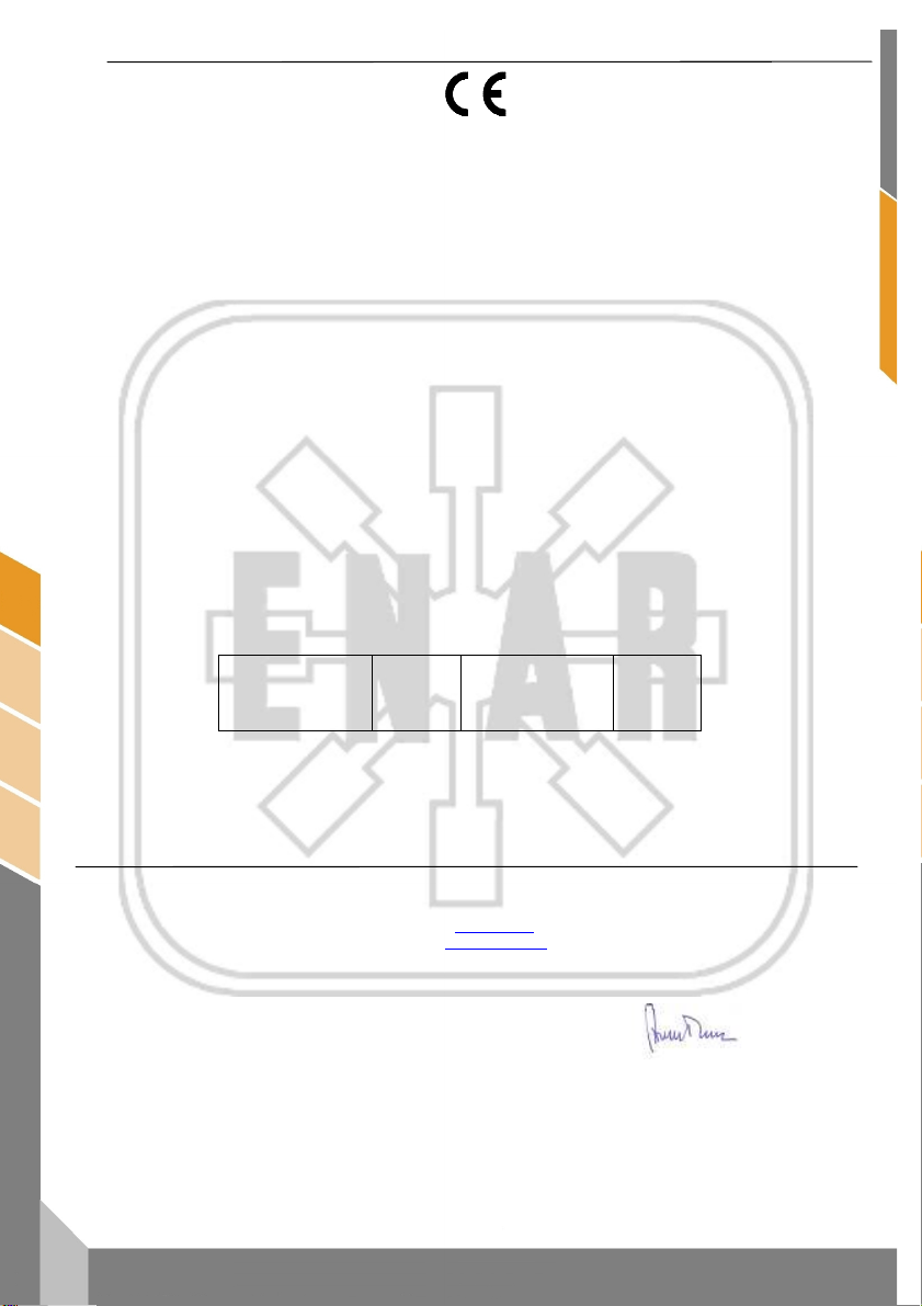
CERTIFICADO DE CONFORMIDAD
CONFORMITY CERTIFICATE ~ CERTIFICAT DE CONFORMITÉ
INSTEMMING VERKLARING ~ KONFORMITÄTS BESCHEINIGUNG
KONFORMITETS BEVIS ~ CERTIFICATO DE CONFORMIDADE ~ CERTIFICATO DI CONFORMITA'
ATITIKTIES DEKLARACIJA ~ CERTYFIKAT ZGODNOŚCI ~ СЕРТИФИКАТ СООТВЕТСТВИЯ
CERTIFICAT DE CONFORMITATE~ СЕРТИФИКАТ ЗА СЪОТВЕТСТВИЕ
certifica que la máquina especificada
hereby certify that the equipment specified bellow ~ atteste que le equipment
verklaart hierbij dat onderstaand gespecificeerde ~ bescheinigt, da
bekræfter, at følgende maskine ~ certifica que o equipamento specificaçao
certifica che la macchina specificata ~ šiuo sertifikatu patvirtina, kad žemiau nurodytas prietaisas, t.y.
Zaświadcza, że wyszczególniona maszyna ~ Подтверждает, что нижеописанная машина
Certifica si declara ca echipamentul mentionat mai jos~ Потвърждаваме, че оборудването, описано по-долу
TIPO DE MAQUINA..................................................................................... Pison Compactador
TYPE~TYPE~TYPE~TYP~TYPE~TIPO~TIPO~TIPAS~TYP~ТИП~TIP~ТИП Tamping Rammer / pilonneuse / Stampfer
MODELO.....................................................................................................PH
MODEL~MODÈLE~MODEL~MODEL~MODEL~MODELO
MODELLO MODELIS~MODEL~МОДЕЛЬ~MODEL~МОДЕЛ
CODIGO...................................................................................................... PH60*, PH70*, PH80*
CODE~CODE~CODE~CODE~CODE~CODIGO~CODICE~KODAS~KOD
КОД~ COD ~ КОД
in overeenstemming met de voldenge voorschriften gefabriceerd is ~ in übereinstimmung mit folgenden richtlinien hergestellt worden ist
Potencia acústica medida (LWA)
Gemessene Schalleistung (LWA)
Puissance acoustique mesurée (LWA)
Measured acoustic power (LWA)
Potência acústica medida (LWA)
Moc akustyczna srednia (LWA)
RESPONSABLE DOCUMENTACIÓN TÉCNICA………. Jesus Tabuenca (ENARCO, S.A. Burtina, 16, 50197 Zaragoza
Technical documentation responsible ~ Responsable of the Documentation Technnique ~ zuständigen technishen Dokumentation
Zaragoza, 01.10.2011
MANUFACTURER:
ENARCO, S.A.
C/Burtina 16
Plat. Logística PLAZA
50197 ZARAGOZA
ha sido fabricada de acuerdo con las siguientes normas
has been manufactured according to the following standards ~ est produit conforme aux dispositions des directives ci-apres
er blevet fremstillet i overenstemmelse med følgende retningslinier ~ é fabricado conforme as seguintes normas
è stata fabbricata secondo le norme vigenti ~ buvo pagamintas laikantis toliau išvardintų standartų
została wyprodukowana zgodnie z następującymi normami ~ Произведена в соответствии со следующими нормами
este fabricat cu respectarea urmatoarelor standarde ~ е производено в съответствие със следните стандарти
2006/42/CE, 2000/14/CE, 2005/88/CE
104
dB (A)
SPAIN
e-mail:
Web:
Tfno.
ENARCO,S.A.
EN 500/1, EN 500/4
Potencia acústica garantizada (LWA)
Garantierte Schalleistung (LWA)
Puissance acoustique garantie (LWA)
Guaranteed acoustic power (LWA)
Potência acústica garantida (LWA)
Moc akustyczna gwarantowana (LWA)
(34) 976 464 090
das Baugerät
β
106
dB (A)
Jose Luis Del Prim
General Manager
ENARCO,S.A.
ENARCO, S.A.
Page 37
ENARCO, S.A.
fr
PILONNEUSE
PH60 - PH70 - PH80
Manuel d'instructions
Page 38

1
fr
PH60, PH70, PH80
INDEX
1 PREAMBULE 2
2 INFORMATIONS DE SÉCURITÉ 3
2.1 SÉCURITÉ DANS LA MANIPULATION DE LA MACHINE 3
2.2 SÉCURITÉ DANS LA MANIPULATION DU MOTEUR 3
2.3 SÉCURITÉ DANS LE SERVICE 4
3 QUELLE MACHINE POUR CHAQUE TRAVAIL? 4
4 MESURES ACOUSTIQUES ET VIBRATOIRES 5
5 MISE EN MARCHE, FONCTIONNEMENT ET ENTRETIEN DE LA MACHINE 5
5.1 AVANT DE COMMENCER LE TRAVAIL 5
5.2 MISE EN MARCHE 5
5.3 TRAVAIL: 6
5.4 ARRET: 6
5.5 TRAVAIL DE MAINTENANCE ET STOCKAGE 7
5.6 LOCALISATION ET REPARATION DES PANNES 9
6 EN CAS DE PANNE 12
7 PLACAS E INDICATIVOS/PLATES AND INDICATIVES/PLAQUES ET INDICATEURS/PLATTEN
UND KENNZEICHEN 13
8 ESPECIFICACIONES TÉCNICAS / TECHNICAL DATA / SPECIFICATIONS TECHNIQUES /
TECHNISCHE DATEN 14
PILONNEUSE
6.1 INSTRUCTIONS POUR COMMANDER DES PIÈCES DE RECHANGE 12
6.2 INSTRUCTIONS POUR FAIRE VALOIR LA GARANTIE 12
Page 39

fr
2
PH60, PH70, PH80
1 PREAMBULE
Nous vous remercions pour la confiance que vous manifestez pour la marque ENAR.
La lecture du présent manuel est importante pour la complète connaissance des
caractéristiques et des opérations de travail du plateau de compactage. Avant de
commencer à travailler avec cette machine ou d’y réaliser des opérations d’entretien, lisez,
comprenez et respectez les instructions de sécurité de ce manuel.
En cas de perte de ce manuel ou si vous voulez un exemplaire supplémentaire, vous
pouvez le demander à ENARCO ou le trouver sous format électronique sur la page web
d’ENARCO:
travail de l’unité.
entretien et ses réparations nous recommandons une consultation du manuel
d’instructions du moteur.
cette machine, mettez-vous en contact avec le service d’assistance d’ENARCO en
appelant par téléphone, en envoyant un fax ou en réalisant une consultation par courrier
électronique à
.
http://www.enar.es
Les procédés corrects d’entretien garantissent une longue durée de vie et un excellent
Même si ce manuel fournit quelques indications à propos du moteur, pour son
Si vous avez besoin d’informations au sujet de la manipulation ou de l’entretien de
[email protected] ou à travers la page web dans la section Service ENAR.
et l’imprimer.
PILONNEUSE
Page 40

3
fr
PH60, PH70, PH80
!
!
2 INFORMATIONS DE SÉCURITÉ
2.1 SÉCURITÉ DANS LA MANIPULATION DE LA MACHINE
Une utilisation ou un entretien incorrects du matériel peuvent entraîner des situations
doutes, demandez des informations à des personnes connaissant parfaitement la machine ou
mettez-vous en contact avec ENARCO.
2.2 SÉCURITÉ DANS LA MANIPULATION DU MOTEUR
de danger. Lisez et assimilez les instructions de cette section avant de commencer à
travailler avec cette machine. L’opérateur du matériel doit être responsable et doit
savoir travailler en respectant les conditions de sécurité du matériel. Si vous avez des
• Le moteur chauffe beaucoup pendant son fonctionnement, laissez-le refroidir avant
de le toucher.
• Ne laissez jamais la machine en marche sans surveillance.
• L’ouvrier doit utiliser des vêtements de protection et des protecteurs auditifs.
• Interdisez l’accès à la zone de travail aux personnes non autorisées.
• Vérifiez que vous savez déconnecter la machine avant de mettre en marche le
moteur au cas où vous rencontreriez des difficultés.
• Arrêtez la machine avant de la transporter.
• N’essayez pas de soulever le matériel sans aide. Demandez de l'aide ou servez-
vous d’un appareil de levage en utilisant le levier intégré à la caisse du plateau.
• N’utilisez pas le matériel si vous n’êtes pas en bonne condition physique.
• Emmagasinez le matériel adéquatement dans un lieu propre et sec .
À cause de sa haute inflammabilité, les combustibles sont particulièrement
dangereux. Leur usage inapproprié peut provoquer de graves dégâts personnels et
matériels. Respectez toujours les règles de sécurité suivantes:
• Ne faites pas fonctionner le matériel à l’intérieur d’un bâtiment ou dans des zones
fermées sans une aération adécuate. Dans le cas contraire, vous pouvez être victime
d’une intoxication au monoxyde de carbone avec perte de connaissance, pouvant
aller même jusqu’à la mort.
• Avant de remplir le réservoir de combustible, arrêtez le moteur et laissez-le refroidir
quelques minutes.
• Vous ne devez pas fumer pendant le fonctionnement de la machine, ni pendant le
ravitaillement en carburant.
• Ne remplissez pas le réservoir près d’une flamme ouverte et remplissez-le dans une
zone bien aérée.
• Si, pendant le ravitaillement, du carburant est déversé, absorbez-le avec du sable.
Changez-vous si vous renversez du carburant sur vos vêtements.
• Assurez-vous que le réservoir de combustible est bien fermé après l’avoir rempli.
• Vérifiez que la tuyauterie et le réservoir de combustible n’ont ni fissures ni fuites.
PILONNEUSE
Page 41
fr
4
PH60, PH70, PH80
MODELE
APLICCATION
Marche
avant
Zones de retouches
#
Fondations
+
Chemins et allées
#
Terrains de sport
#
Préparation de base
+ # #
Support final ponts et rampes
+ + #
Intersection de chemin de fer
+ + #
Blocs de ciment
# +
Construction de routes
+ # +
Construction de drains
+ +
Compactage de tranchées
+ +
Réparation de trous (canalisations..
# +
Contour des canalisations, cables
# # +
Remplissage de gravas
Gravier
+ + +
Sable ou matériau volcanique
+ + #
Sols mixtes
+ # +
Boue + + Argile + + Couche d'une épaisseur de 0-25 cm
+ + +
Couche d'une épaisseur de 20-40 cm
+ +
Mélange chaud
# + #
Mélange froid
# + #
Base de mélange 40-100 mm
+ # +
Couche d'enrobé 25-60 mm
# +
2.3 SÉCURITÉ DANS LE SERVICE
• Ne nettoyez pas et ne révisez pas le matériel pendant son fonctionnement.
• Ne faites pas démarrer le moteur avec le cylindre inondé ou en ayant retiré la bougie
des moteurs d’essence.
• Ne vérifiez pas que la bougie fait des étincelles si le cylindre est inondé d’essence ou
s’il y a des vapeurs d’essence.
• N’utilisez pas de dissolvants ou de combustibles pour nettoyer le matériel, surtout
dans des lieux fermés.
• Maintenez le silencieux dans un périmètre de sécurité loin de matériaux
inflammables.
• Avant de faire des opérations de service sur des équipements avec un moteur à
essence, déplacez la bougie pour éviter un démarrage imprévu du moteur.
• Il n’est pas permis d’utiliser le matériel dans des atmosphères explosives. Le
réservoir de combustible doit fermer hermétiquement. Dans des transports de longue
distance il est vivement recommandé de vider de combustible le réservoir du moteur.
• L’accessoire de transport n’a pas été conçu pour qu’on y garde le plateau, utilisez-le
seulement pour déplacer la machine.
3 QUELLE MACHINE POUR CHAQUE TRAVAIL?
Plaques reversibles
# Peut être utilise + Recommandé
Pilonneusos
PILONNEUSE
Page 42
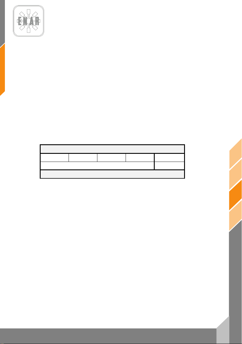
60,
70, P
4 MESURES ACOUSTIQUES ET VIBRATOIRES
- Niveau de puissance acoustique selon EN 500-4: LWA 106 dB(A)
- Niveau de pression sonore selon EN 500-4: L
- Valeur effective pondérée d’accélération axiale selon EN 500-4:
96 dB(A)
pA
Ahv 6,8
2
m/s
5 MISE EN MARCHE, FONCTIONNEMENT ET ENTRETIEN DE
LA MACHINE
5.1 AVANT DE COMMENCER LE TRAVAIL
5.1.1. Les mécanismes de cette machine se lubrifient par bain d’huile. Vérifiez le
niveau d’huile à travers le voyant qui se trouve sur la partie postérieure en dessous du
soufflet. Ajoutez de l’huile s’il n’était pas possible de voir l’huile par le voyant jusqu’à ce
qu’elle couvre la moitié du voyant.
5.1.2. Remplissez le réservoir de combustble avec le type de carburant adapté au
MODELE DE MOTEUR
HONDA GX120 HONDA GX100 ROBIN ER12 ROBIN EH12 YANMAR L48
Utilisez un carburant de haute qualité qui soit spécial pour des moteurs deux temps, ou
sinon bien mélanger l’essence avec de l’huile de synthèse spéciale prévue à cet effet dans
une proportion de 50:1. Quand vous remplissez le réservoir, assurez-vous de filtrer le
combustible avec une passoire. N’oubliez pas de mettre le bouchon de remplissage et de
le fermer, étant donné que sans lui le travail est dangereux, parce que des projections de
combustible dues aux secousses pourraient se produire et par conséquent pourraient
arriver à s’enflammer et à brûler.
5.1.3. Vérifiez le serrage de chaque boulon, écrou ou zones de serrage. Un vis
5.1.4. Eliminez la saleté et la poussière. Nettoyez spécialement la zone à côté du
5.2 MISE EN MARCHE
moteur qui équipe votre machine selon le tableau.
ESSENCE SANS PLOMB
desserré par les secousses peut entraîner un sérieux problème inattendu.
Soyez sûr d’avoir serrer toutes les zones de serrage.
démarreur de recul et du pied.
TYPE DE CARBURANT
GAS-OIL A
fr
5.2.1. Ouvrez le robinet de carburant en déplaçant le levier vers le bas. Fermez le
levier du régulateur d’air et mettez le levier de la soupape d’étranglement d’air sur la
position semi-ouverte. Pour mettre en marche le moteur à froid déplacer le levier du
régulateur d’air jusqu’à la position de fermeture. Quand le moteur est chaud, le régulateur
d’air doit être ouvert à moitié ou complètement. Si la mise en marche du moteur est
difficile, assurez-vous que le levier du régulateur d’air est à moitié ouvert pour éviter que le
carburateur soit noyé par excès de combustible.
5.2.2. Quand vous tirez la corde de démarrage, ne la tirez pas au maximum de sa
longueur, cela peut endommager le ressort de rappel. Ne lâchez pas la corde d’un coup
pour remettre en marche une fois le moteur démarré, maintenez la poignée dans votre
main et retenez-la lentement jusqu’à ce qu’elle s’enroule à nouveau totalement.
PILONNEUSE
PH
PH
5
H80
Page 43

fr
6
PH60, PH70, PH80
5.3 TRAVAIL:
5.3.1. Après avoir démarré le moteur, rouvrez complètement de façon graduelle le
levier du régulateur d’air. Laissez le moteur chauffer en vitesse minimum pendant 3-5
minutes. Cette procédure de chauffer le moteur en révolutions minumums est
particulièrement importante pendant la saison froide. Pendant que le moteur est en train de
chauffer, faites une révision générale de la machine pour détecter une quelconque
anomalie.
5.3.2. Le piston commence à fonctionner quand on tourne le levier de l’accélérateur
en le déplaçant rapidement d’¼ de tour. Si le levier se déplace lentement, l’action du piston
sera irrégulière et l’embrayage, le ressort ou sa jambe sera endommagé.
5.3.3. Après que la machine commence à fonctionner, réglez le mouvement de
vibration de telle manière qu’il s’adapte à la condition particulière du sol, en controlant
légèrement le levier de l’accélérateur. Ce piston a été dessiné de telle sorte que, quand le
moteur travaille à une vitesse comprise entre 3.600 et 4.000 r.p.m., sa jambe frappe la
superficie du sol 600 à 700 fois par minute, ce qui permet une meilleure efficacité dans le
travail. Une augmentation qui n’est pas nécessaire de la vitesse du moteur n’entraîne pas
une augmentation de la force de compactage, au contraire, la résonnance qui en résulte
fait que la force de compactage diminue, endommageant la machine.
5.3.4. En période froide, comme l’huile qui existe dans la machine est visqueuse, la
résistance dans la partie alternante est plus grande, entraînant un mouvement quelque
peu irrégulier de la dame à secousses, Par conséquent, avant de commencer le travail on
recommande de faire fonctionner la machine pour la faire chauffer pendant qu’on déplace
le levier de l’accélérateur plusieurs fois entre les positions 0 - ¼ de tour.
5.3.5. La surface de la jambe en contact avec le sol est revêtue d’une plaque
métallique traitée thermiquement. Cependant, pour compacter des galets, il est conseillé
d’utiliser un remblai de matériau fin, du sable par exemple, de telle manière que l’extrémité
postérieure de la surface plane de la jambe se trouve en contact avec le terrain.
5.3.6. La dame à secousses a été dessinée pour qu’elle avance pendant qu’elle vibre.
Pour obtenir une avancée plus rapide, levez la machine en la tirant légèrement vers
l’arrière, de telle manière que l’extrémité postérieure de la surface plane de la jambe se
trouve en contact avec le terrain.
5.4 ARRET:
5.4.1. Pour arrêter le travail, et inversement à la mise en marche, déplacez
5.4.2. Avant d'arrêter le moteur, laisser le touner pendant 2 ou 3 minutes au ralenti et
5.4.3. Fermer le réservoir de carburant, en plaçant la durite en position horizontale.
rapidement le levier de l’accélérateur de la position ¼ à 0.
ensuite appuyer sur le bouton d'arrêt jusqu'à l'arrêt complet du moteur.
PILONNEUSE
Page 44
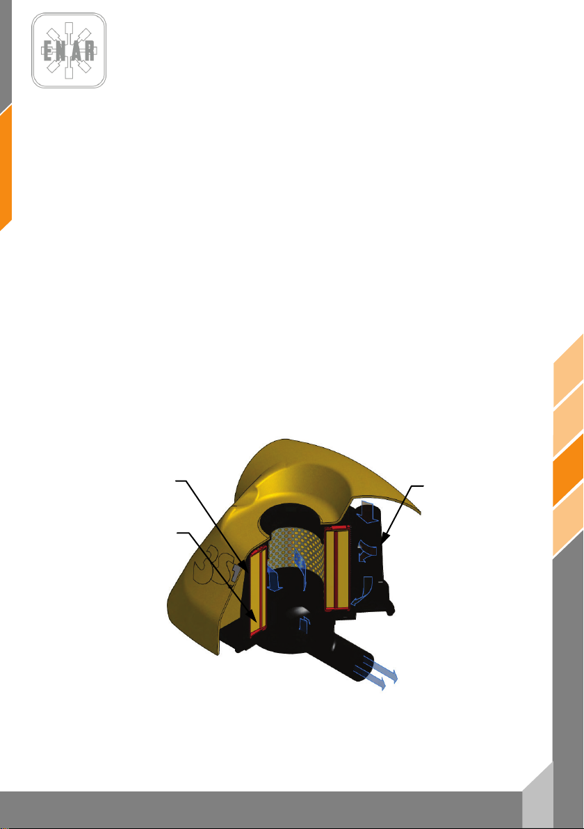
7
fr
PH60, PH70, PH80
2ª ETAPE
1ª ETAPE
3ª ETAPE
5.5 TRAVAIL DE MAINTENANCE ET STOCKAGE
5.5.1. Avant de réaliser n’importe quel travail de maintenance sur la dame à
5.5.2. Travail de maintenance journalier:
Eliminez entièrement de la machine toute la saleté, la poussière ou l’huile. Contrôlez le
filtre à air, en le nettoyant au besoin. Serrez de nouveau les endroits oû on peut remarquer
une fuite d’huile et vérifiez que toutes les autres zones se trouvent serrées.
5.5.3. Travail de maintenance hebdomadaire (toutes les 50 heures):
Retirez le couvercle du filtre à air et nettoyez l’élément interne avec une solution
nettoyante neutre. Après l’avoir séché, appliquez un carburant mixte d’essence et d’huile
(si c’est possible employer le carburant utilisé), et bien mélangez. Puis, pressez
légèrement l’élément primaire externe (éponge) et placez-le sur l’élément secondaire
interne pour le monter.
Ajustez sur la bougie la distance entre électrodes à une valeur égale à 0.7 – 0.8 mm.
Retirez le bouchon de remplissage d’huile (situé au dessus du verre de niveau d’huile),
placez la machine horizontalement de manière que l’orifice de remplissage d’huile serve
pour la vidange de l’huile usée et en plaçant la machine avec l’orifice vers le bas pour
vidanger totalement l’huile.
Placer de nouveau la machine debout et par le même orifice, remplissez d’huile neuve au
moyen d’un entonnoir, jusqu’ à atteindre le niveau du verre d’huile.
Le premier changement d’huile se réalisera au bout de 50 heures de fonctionnement, à
partir de la deuxième fois toutes les 300 heures de travail.
5.5.4. Maintenance conditionnelle grâce au capteur de colmatage du filtre à air (Si
secousses, ARRETEZ TOTALEMENT LE MOTEUR
présent), ou systématique chaque quinze jours (100 heures):
PILONNEUSE
ÉTAPES DE FILTRAGE
Page 45
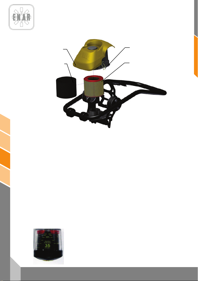
fr
8
PH60, PH70, PH80
3
4
1
2
Détachez les crochets de fixation (2) Retirez le cache du filtre à air (1). Extraire le préfiltre
(Éponge)(3) et la cartouche du filtre à air (4). Secouez et soufflez de l’intérieur vers
l’extérieur le filtre à air. Nettoyez le préfiltre avec une solution neutre (pH-neutre), puis
aprés l’avoir séché, imprégnez le dans une solution d’essence mélangé avec de d’huile,
ensuite secouez le bien.
Pour terminer, pressez légèrement le préfiltre, puis montez le sur le filtre avant de placer
l’ensemble sur la carcasse inférieur du filtre, ensuite mettez la carcasse superieur et fixez
la avec les crochets.
5.5.5. Travail de maintenance mensuel (toutes les 300 heures):
Nettoyez l’intérieur du réservoir de carburant. Nettoyer chaque partie de la machine et
serrer de nouveau les boulons et les écrous au besoin.
5.5.6. Stockage correcte:
Pour un stockage prolongé après la fin d’un travail, drainez complétement le carburant de
l’intérieur du réservoir, du tuyau de carburant et du carburateur.
Retirez la bougie d’allumage, versz quelques gouttes d’huile dans le cylindre et
manuellement faites que le moteur fasse quelques tours, de tel manière que l’huile
atteigne tous les points. En ce qui concerne à l’extérieur, nettoyez-le avec un chiffon
humecté d’huile.
Stockez la machine en la couvrant d’une housse, dans un lieu libre d’humidité et de
poussière et en évitant les rayons directs du soleil.
5.5.7. Maintenance conditionnelle grâce au capteur de colmatage filtre
Si la machine dispose d’un capteur de colmatage du filtre à air, le
corp jaune du capteur se déplacera en fonction du colmatage du
filtre, jusqu’à atteindre la zone rouge indiquant ainsi la nécessité
d’un entretien du filre à air en suivant les indications du point 5.5.1;
réarmez le capteur en pressant sur le bouton jaune du filtre.
PILONNEUSE
Page 46

9
fr
PH60, PH70, PH80
5.5.8. Fonctionnement du tachymètre.
Lorsque le moteur est à l’arrêt l’afficheur indiquera la valeur du
temps total de fonctionnement, cette valeur ne peut être remise
à zéro.
Lorsque le moteur est en marche l’afficheur nous indiquera la
vitesse en RPM (Rotation par minute). Pour afficher le temps
de fonctionnement partiel appuyez sur “SELECT”. Pour la
remise à zéro du temps partiel de fonctionnement vous devez
appuyez longuement sur “SELECT” puis relacher.
Avec moteur diesel:
Alarme d’entretien SVC2: Aprés 50 heures de fonctionnement le tachymètre affichera
l’alarme SVC2. Effectuez l’entretien prévu, puis réinitialiser le compteur en appuyant sur
“RESET” trois fois et maintenez jusqu'à ce que RESET soit affiché.
Alarme d’entretien SVC: Après 250 heures de fonctionnement le tachymètre affichera
l’alarme SVC. Effectuez l’entretien prévu, puis réinitialiser le compteur en appuyant sur
“RESET” deux fois et maintenez jusqu'à ce que RESET soit affiché.
5.6 LOCALISATION ET REPARATION DES PANNES
MOTEUR ESSENCE
Ne démarre pas:
- Il y a du carburant mais la bougie ne fonctionne pas
• Courant dans le cable de haute tension
Bougie de démarrage coincée.
Dépot de charbon dans la bougie d'allumage
Court circuit du a une mauvaise isolation de la bougie d'allumage.
Ajustement incorrect entre les électrodes.
• Pas de courant dans le cable de haute tension
Court circuit de l'interrupteur.
Bobine d'allumage défectueuse.
Isolation du condensateur défectueuse ou en court circuit.
Bobine d'allumage cassée ou en court circuit.
• Compression satisfaisante
Carburant incorrect.
Entrée d'eau ou de poussière
- Il y a du carburant et la bougie fonctionne correctement
Filtre à air défectueux.
• Compression insuffisante
Valve d'admission ou d'échappement collée ou défectueuse
Bague du piston ou du cylindre défectueuse.
Culasse du cylindre ou de la bougie mal ajustée.
Joint de culasse ou de la bougie défectueuse.
• L'embrayage bloqué et le vibrateur tourne lors du démarrage
• Pas de carburant dans le carburateur
-Réservoir d'essence vide.
-La durite du carburnt n'est pas correctement ouverte.
-Filtre à essence obstrué.
-Sortie d'air du réservoir obstrué.
-Air dans le tube.
-Valve d'entrée du carburateur collée.
PILONNEUSE
Page 47

fr
10
PH60, PH70, PH80
Puissance nulle:
- Puissance insuffisante
• Compression normale et pas de probleme d'allumage
Filtre à air usé.
Dépot de charbon dans le cylindre.
Niveau de carburant dans le carburateur incorrect.
• La compression est correcte mais problème de démarrage.
(Voir compression insuffisante )
• Vibrateur plein avec excès d'huile
-Présence d'eau dans le carburant.
-Bougie d'allumage sale.
-Bobine d'allumage défectueuse.
- Rechauffement du moteur
- Vitesse de marche irrégulière
Puissance du démarreur insuffisant
- Partie rotative collée avec de la poussière
- Ressort hélicoidal défectueux.
MOTEUR DIESEL. (Refroidissement par air)
Démarrage défectueux:
A.- Compression insuffisante
B.- Injection incorrecte dans la chambre de combustion
-Court circuit fréquent de la bobine d'allumage.
• Depot de charbon dans la chambre de combustion ou dansle pot
d'échappement
• Puissance de rechauffement de la bougie incorrecte.
• Ailettes de refroidissement sales.
• Réglage du régulateur incorrect.
• Ressort du régulateur incorrect.
• Niveau de carburant incorrect.
• Entrée d'air dans la durite.
• Compression nulle
Valve d'entrée ou d'échappement défectueux.
Réglage du système de décompression incorrect.
• Compression très faible.
Contact de la valve défectueuse.
Bague du piston usée
Cylindre usé.
Réglage du cylindre et de la culasse du cylindre défectueuse.
Injection dévissée
• Niveau de carburant faible ou insuffisant
Sortie d'air du réservoir obstrué.
Filtre à essence et tamis du filtre obstrués.
Clé du filtre à essence fermée.
Air dans le tube (en particulier lorsque le réservoir est vide.
• Pas d'injection dans la chambre de combustion.
Cylindre de la pompe à injection ou piston collé.
Injection obstruée.
Aguille de l'injection collée.
PILONNEUSE
Page 48

11
fr
PH60, PH70, PH80
• Réservoir d'essence vide.
• Entrée d'air ou de poussière
C.- Système de carburant et de compression correcte mais ne démarre pas :
• N'arrive pas à démarrer.
Processus de démarrage incorrect.
Haute viscosité ou contamination excessive de l'huile du moteur.
Puissance de sortie insuffisante. Compression insuffisante:
Air dans le tube.
• Réchauffement du moteur et échappement sale.
Ailettes de refroidissement sales.
Présence d'eau dans le filtre à essence
Dépot de charbon dans la chambre de combustion, dans le pot
d'échappement.
Réglage de la fumée incorrect.
Surcharge.
Regulation de l'injection incorrecte.
Injection obstruée.
• La vitesse change.
Contact incorrect entre la grille du régulateur et la poignée.
Ressort du régulateur incorrect.
Plaque du vilebrequin et autres plaques usées ou fonctionnement
défectueux.
• La vitesse du moteur n'augmente pas correctement
Synchronisation de la valve incorrecte.
Pot d'échappement ou silencieux obstrué.
Surcharge.
• Allumage défectueux accompagné de fumée blanche
Piston, cylindre ou segments usés.
Injection obstruée.
Bague du piston supérieur et inférieur montés à l'envers
Reglage de l'avancement de l'injectin incorrecte.
Synchronisation de la valve incorrecte.
Joint de la pompe à injection incorrect.
• Haute consommation d'essence. (On observe un échappement
obscur).
Fuite d'essence.
Element du filtre à air obstrué.
Combustible defectueux car il contient des impuretés.
Surcharge.
• Partie glissante excessivement usée ou segment du piston coincé
Utilis ation d'huile défectueuse
Remplacement de l'huile incorrecte.
Element du filtre à air défectueux ou sale.
• Bruit anormal
Engrenage ou piston endommagé.
• Huile pour la lubrification diluée, augmentant son volume
Corps du piston de la bombe d'injection usé
• Le moteur ne s'arrête pas, bien qu'on arrête l'entrée d'essence
Trop d'huile.
Installation du système de régulation incorrecte.
Chassis de la pompe à injection déplacée.
PILONNEUSE
Page 49

fr
12
PH60, PH70, PH80
OPERATION DE LA MACHINE
Vitesse de translation lente et vibration faible.
Translation oblique
• Le régulateur ne s'ouvre pas à la vitesse du moteur.
(page 10)
• Puissance du moteur insuffisante.
• L'embrayage patine.
• Huile du vibrateur excessive.
• Parties internes du vibrateur défectueuses.
Avance ou recule mais on ne peut rien changer.
• Réglage incorrect du ralenti ou marche arrière
• Engrenage du vibreur dèfectueux
• Parties du sélecteur de sens de translation défectueuses
N’avance pas et ne recule pas
• L'embrayage patine.
• Vibrateur entravé.
• Si vibre mais ne se déplace pas, le vibrateur peut se trouver
sur une superficie humidifiée et glissante.
Essayer dans une superficie correcte.
6 EN CAS DE PANNE
6.1 INSTRUCTIONS POUR COMMANDER DES PIÈCES DE RECHANGE
1. Dans toutes les commandes de pièces de rechange, ON DOIT INCLURE LA
RÉFÉRENCE DE LA PIÈCE SELON LA LISTE DE PIÈCES. Il est recommandé
d’inclure le NUMÉRO DE FABRICATION DE LA MACHINE.
2. La plaque d’identification avec les numéros de série et le modèle se trouvent sur la
partie supérieure de la base moteur.
3. Fournissez-nous les instructions de transport correctes, en précisant la route
préférée, l’adresse et le nom complet du consignataire.
4. Ne retournez pas de pièces de rechange à l’usine à moins d’en avoir l’autorisation
écrite, tous les retours autorisés devront être envoyés en port payé.
6.2 INSTRUCTIONS POUR FAIRE VALOIR LA GARANTIE
1. La garantie a une validité d’1 an à partir de l’achat de la machine. La garantie
couvrira les pièces présentant un défaut de fabrication.
- En aucun cas la garantie ne couvrira une panne pour un mauvais usage de la
machine.
2. Dans toutes les demandes de garantie, IL FAUT ENVOYER LA MACHINE À
ENARCO, S.A. OU ATELIER AGRÉÉ, en indiquant toujours l’adresse et le nom
complet du consignataire.
3. Le département de Service Technique notifiera si la garantie est acceptée, et en cas
de demande, un rapport technique sera envoyé.
4. Il n’y aura aucun type de garantie sur toute machine qui aurait été manipulée au
préalable par des personnes non rattachées à ENARCO, S.A.
REMARQUE : ENARCO, S.A. se réserve le droit de modifier n’importe quelle donnée de ce
manuel sans avis préalable
PILONNEUSE
Page 50
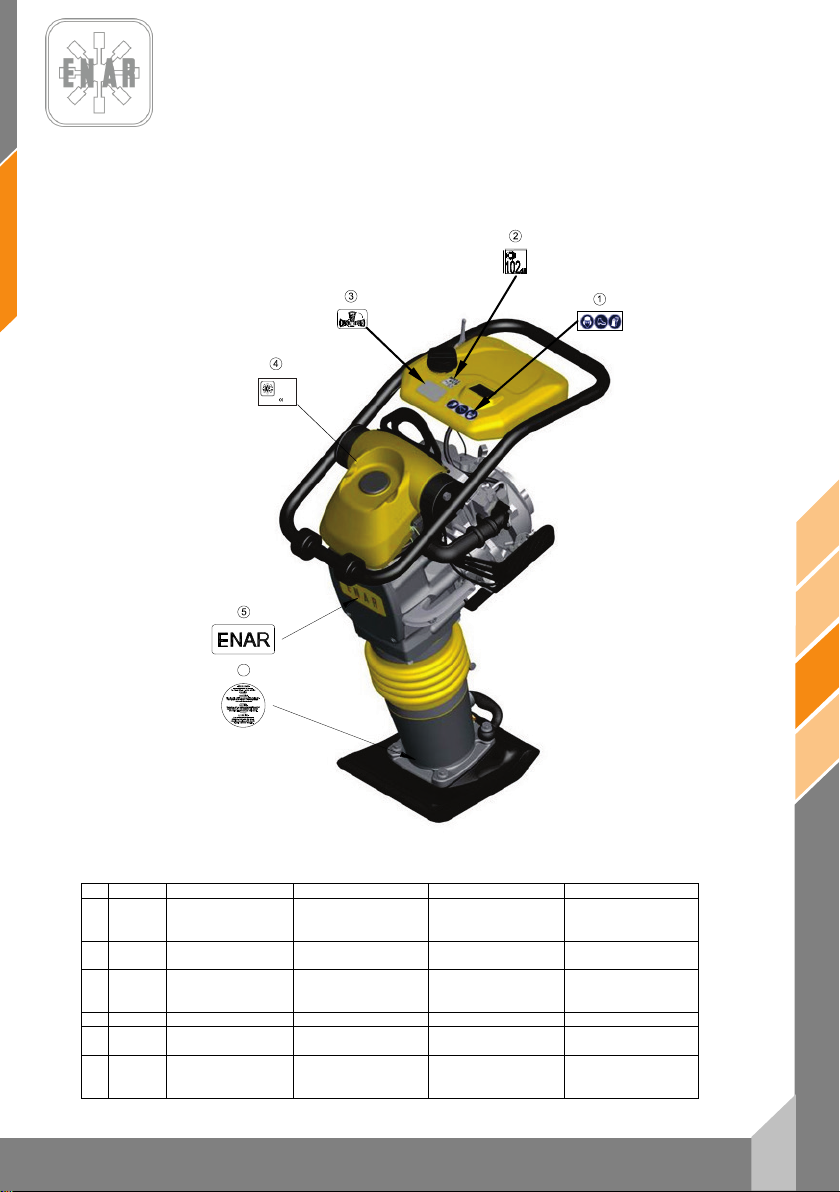
13
fr
PH60, PH70, PH80
Nº
REF.
DESCRIPCION
DESCRIPTION
DESIGNATION
BENENNUNG
ADHESIVO
SEGURIDAD
SAFETY
STICKER
ADHÉSIF
SÉCURITÉ
ADHESIVO 104 Dba
ADHESIF
104 Dba
ADHESIVO
DERECHO
4
RC6506
ANAGRAMA ENAR
ENAR STICKER
AUTOCOLANT ENAR
ENAR KLEBSTOFF
ADHESIVO
CARÁCTERÍSTICAS
CHARACTERISTICS
STICKER
AUTOCOLANT
CARACTÉRISTIQUES
MERKMALE
KLEBSTOFF
ADHESIVO
MUELLES
STICKER
SPRINGS
ADHÉSIF
RESSORTS
KLEBSTOFF
SPRUNGFEDER
L
WA
PHX0H
00000000
ENARCO, S.A.
C/ Burtina, 16
2012
50197 Zaragoza
(SPAIN)
6
7 PLACAS E INDICATIVOS/PLATES AND INDICATIVES/PLAQUES
ET INDICATEURS/PLATTEN UND KENNZEICHEN
1 107228
2 107402
3 107284
5
6 107225
PILONNEUSE
PROTECCION
TUMBADO
PRECAUCION
PROTECTION
104 dBA STICKER
PLACE RIGHT SIDE
STICKER
PRECAUTION
PROTECTEUR
ADHÉSIF TOMBÉ À
DROIT
PRECAUTION
SCHUTZKLEBSTOFF
104 dBA KLEBSTOFF
RECHTGELIEGENER
KLEBSTOFF
ACHTUNG
Page 51
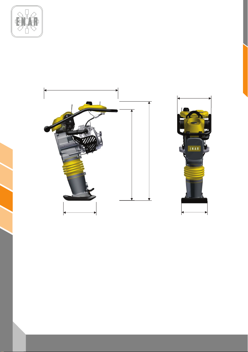
fr
14
PH60, PH70, PH80
368
280
772
1038
953
8 ESPECIFICACIONES TÉCNICAS / TECHNICAL DATA /
SPECIFICATIONS TECHNIQUES / TECHNISCHE DATEN
PILONNEUSE
Page 52
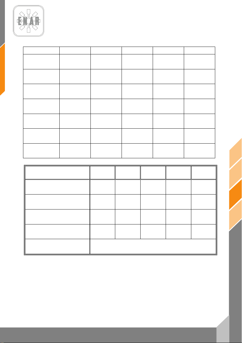
15
fr
PH60, PH70, PH80
HONDA
GX100 DKR
ROBIN
ER12
HONDA
GX120 DKR
ROBIN
EH12 D
YANMAR
L48 AE
COMBUSTIBLE (L)
BRENNST OFF (L)
ACEITE MOTOR (L)
MOTORENÖL (L)
POTENC IA NOMINAL
NENNLEISTUNG
BUJÍA
ZÜNDKERZE
ENTREHIERRO
LUFTSPALT
R.P.M.
U-MN
RALE NTÍ
LEERLAUFD REHZAHL
PESO SIN COMBUSTIBLE (Kg)
GEWICHT (Kg)
ELEVACIÓN DEL PISÓN (mm)
SPRINGWEG (mm)
NUMERO DE GOLPES POR MINUTO
EINSCHLAGSFREQUENZ
MOTOR
MOTOR
LUBRICANTE MÁQUINA (L)
MASCHINENOEL (L)
FUEL (L)
COMBUSTIBLE (L)
SIN PLOMO (2.7) SIN PLOMO (2.7) SIN PLOMO (2,7) SIN PLOMO (2,7) GAS-OIL (2,7)
ENGINE OIL (L)
HUILE MOTEUR (L)
NOMINAL POWER
PUISSANCE NOMINALE
SPARK PLUG
BOUGIE
GAP
ENTREFER
R.P.M.
TR-MN
IDLING
RÉGIME RALENTI
SAE 10W/40 (0,6) SAE 10W/40 (0,4) SAE 10W /40 (0,3) SAE 10W/40 (0,4) SAE 10W/40 (0,8)
3 kW (4 HP) 3 kW (4 HP) 3 kW (4 HP) 2,6 kW (3,5 HP) 3,1 kW (4,1 HP)
NGK CR5HSB
DENSO U16FSR-UB
0,6 mm - 0,7 mm 0,6 mm - 0,7 mm 0,7 mm - 0,8 mm 0,6 mm – 0,7 mm
4000 rpm ± 50 4000 rpm ± 50 3500 rpm ± 50 3600 rpm ± 50 3600 rpm ± 50
1700 ±150 r.p.m. 1700 ±150 r.p.m. 1500 ±150 r.p.m. 1600 ±150 r.p.m. 1500 ±150 r.p.m.
NGK CR5HSB
DENSO U16FSR-UB
NGK BP4ES
DENSO W14EP -U
NGK B6ES
CHAMPION N4C
----
----
ESPECIFICACIONES PH60H PH60R PH70H PH70R PH80YD
WEIGHT WITHOUT COMBUSTIBLE (Kg)
POIDS SANS COMBUSTIBLE (Kg)
IMPACT COURSE HEIGHT (mm)
PARCOURS DE FRAPPE (mm)
NUMBER OF BLOWS BY MINUTE
FREQUENCE D’IMPACTS PAR MINUTE
ENGINE
MOTEUR
MACHINE OIL (L)
HUILE POUR MACHINE (L)
68 68 72 72 80
60 65 70 70 70
700 700 700 700 700
HONDA
GX100U
ROBIN
ER12
SAE 30 / ISO 100 (1.8 L.)
ROBIN
GX120U
ROBIN
EH12D
YANMAR
L48AE
PILONNEUSE
Page 53
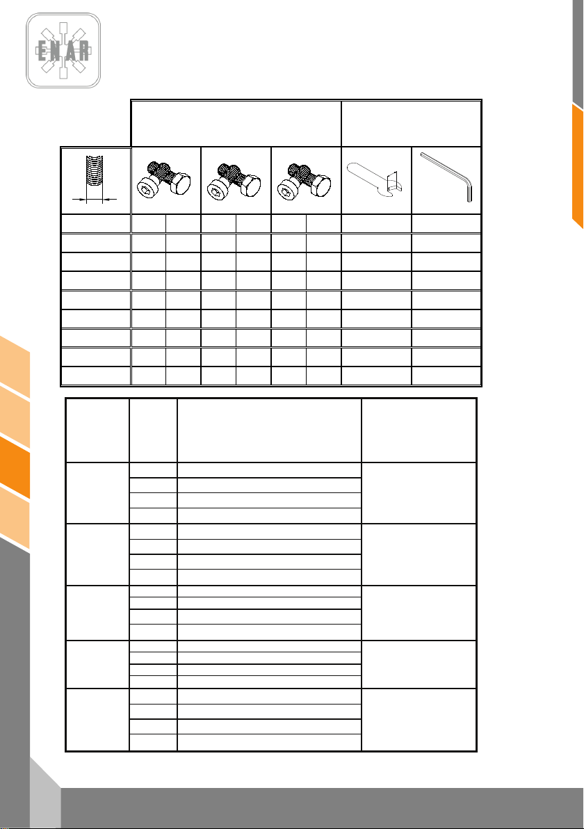
fr
16
PH60, PH70, PH80
PAR DE APRIETE
TORQUE
COUPLE
DREHMOMENT
TAMAÑ O DE LLAVE
SPANNER SIZE
DIMENSION DE LA CLEF
GRÖSSE VON DEM
SCHRAUBERSCHLÜSSEL
8.8
10.9
12.9
MÉTRICA
Ft.Lb.
Nm
Ft.Lb.
Nm
Ft.Lb.
Nm
mm
mm
M4
*26
2.9
*36
4.1
*43
4.9
7
3
M5
*53
6.0 6 8.5
7 10
8
4
M6
7
10
10
14
13
17
10
5
M8
18
25
26
35
30
41
13
6
M10
36
49
51
69
61
83
17
8
M12
63
86
88
120
107
145
19
10
M14
99
135
140
190
169
230
22
12
M16
155
210
217
295
262
355
24
14
* = In.Lb. 1 Ft.Lb. = 1.357 Nm 1 Inch = 25.4 mm
TIPO
TYPE
TYPE
TYP
COLOR
COLOR
COLEUR
FARBE
USO
USE
USAGE
GEBRAUCH
Nº PIEZA/TAMAÑO
PARTNUMBER/SIZE
Nº PIÈCE/DIMENSION
TEILNUMMER/GRÄSSE
Morado
Resistencia baja, para fijar roscas menores a M36.Resiste
desde -54º a 149ºC.
Purple
Low strength, for locking threads smaller than M36.Temp.
Range –54º to 149ºC.
Violette
Peu de resistence pour fixer des filets plus petits que la M36.
Elle resiste de –54º jusqu’à 149ºC.
Loctite 222
Hernon 420
Omnifit 1150 (50M)
Dunkelviolett
Niedrieger widerstandskraft, um Gewinde kleiner als M36 zu
befestigen. Das widersteht von –54º bis 149ºC.
124151 – 10 ml
Azul
Resistencia media, para fijar roscas mayores a M36.Resiste
desde -54º a 149º C.
Blue
Medium strength, for locking threads larger than M36.Temp.
Range –54º to 149ºC
Bleue
Resistence moyenne pour f ixer des filets jusqu’â M36. Elle
resiste de –54º jusqu’â 149ºC.
Loctite 243
Hernon 423
Omnifit 1350 (100M)
Blau
Medium widerstandskraft, um grösser als M36 Gewinde zu
befestigen. Das widersteht von 54º bis 149ºC.
124152 – 0.5 ml
124155 – 50ml
Blanco Sellador de tuberías con Teflón . Resiste desde -54º a 149º C.
White Pipe sealant with Teflon. Temp. Range –54º to 1 49º C.
Blanque
Colle de tuyanterie avec teflon. Elle resiste de –54º jusqu’à
149ºC.
Loctite 592
Hernon 920
Omnifit 790
Weis
Klebstoff mit teflon für Rohrleitung en. Das widerstehr von –54º
bis 149ºC.
6 ml
50 ml
Transparente Adhesivo estructural para metal. Resiste desde -54º a 82º C.
Clear Instant adhesive for metal. Temp. Range –54º to 82º C.
Transparente Colle instantanée pour metal. Elle resiste de –54º jusqu’à 149ºC
Loctite 495
Deurchsichtig Sofortiger klebstoff für metal. Das widersteht von –54º bis 82ºC
124156 – 1 oz.
Verde
Producto anaeróbico de retención de alta resistencia, tolerante
al aceite.
Green
High resistant product, wich doesn´t need air to re act and bears
the oil.
Verte
Producte anaérobie de rétention d’haute resi stence, tolérant au
huile.
Loctite 601
Grün
Stoff von grösser widerstandskraft, der ohne sauerstoff reagiert
und das öl zulässt.
124154 – 6 oz.
PILONNEUSE
Page 54
CERTIFICADO DE CONFORMIDAD
CONFORMITY CERTIFICATE ~ CERTIFICAT DE CONFORMITÉ
INSTEMMING VERKLARING ~ KONFORMITÄTS BESCHEINIGUNG
KONFORMITETS BEVIS ~ CERTIFICATO DE CONFORMIDADE ~ CERTIFICATO DI CONFORMITA'
ATITIKTIES DEKLARACIJA ~ CERTYFIKAT ZGODNOŚCI ~ СЕРТИФИКАТ СООТВЕТСТВИЯ
CERTIFICAT DE CONFORMITATE~ СЕРТИФИКАТ ЗА СЪОТВЕТСТВИЕ
certifica que la máquina especificada
hereby certify that the equipment specified bellow ~ atteste que le equipment
verklaart hierbij dat onderstaand gespecificeerde ~ bescheinigt, da
bekræfter, at følgende maskine ~ certifica que o equipamento specificaçao
certifica che la macchina specificata ~ šiuo sertifikatu patvirtina, kad žemiau nurodytas prietaisas, t.y.
Zaświadcza, że wyszczególniona maszyna ~ Подтверждает, что нижеописанная машина
Certifica si declara ca echipamentul mentionat mai jos~ Потвърждаваме, че оборудването, описано по-долу
TIPO DE MAQUINA..................................................................................... Pison Compactador
TYPE~TYPE~TYPE~TYP~TYPE~TIPO~TIPO~TIPAS~TYP~ТИП~TIP~ТИП Tamping Rammer / pilonneuse / Stampfer
MODELO.....................................................................................................PH
MODEL~MODÈLE~MODEL~MODEL~MODEL~MODELO
MODELLO MODELIS~MODEL~МОДЕЛЬ~MODEL~МОДЕЛ
CODIGO...................................................................................................... PH60*, PH70*, PH80*
CODE~CODE~CODE~CODE~CODE~CODIGO~CODICE~KODAS~KOD
КОД~ COD ~ КОД
in overeenstemming met de voldenge voorschriften gefabriceerd is ~ in übereinstimmung mit folgenden richtlinien hergestellt worden ist
Potencia acústica medida (LWA)
Gemessene Schalleistung (LWA)
Puissance acoustique mesurée (LWA)
Measured acoustic power (LWA)
Potência acústica medida (LWA)
Moc akustyczna srednia (LWA)
RESPONSABLE DOCUMENTACIÓN TÉCNICA………. Jesus Tabuenca (ENARCO, S.A. Burtina, 16, 50197 Zaragoza
Technical documentation responsible ~ Responsable of the Documentation Technnique ~ zuständigen technishen Dokumentation
Zaragoza, 01.10.2011
MANUFACTURER:
ENARCO, S.A.
C/Burtina 16
Plat. Logística PLAZA
50197 ZARAGOZA
ha sido fabricada de acuerdo con las siguientes normas
has been manufactured according to the following standards ~ est produit conforme aux dispositions des directives ci-apres
er blevet fremstillet i overenstemmelse med følgende retningslinier ~ é fabricado conforme as seguintes normas
è stata fabbricata secondo le norme vigenti ~ buvo pagamintas laikantis toliau išvardintų standartų
została wyprodukowana zgodnie z następującymi normami ~ Произведена в соответствии со следующими нормами
este fabricat cu respectarea urmatoarelor standarde ~ е производено в съответствие със следните стандарти
2006/42/CE, 2000/14/CE, 2005/88/CE
104
dB (A)
SPAIN
e-mail:
Web:
Tfno.
ENARCO,S.A.
EN 500/1, EN 500/4
Potencia acústica garantizada (LWA)
Garantierte Schalleistung (LWA)
Puissance acoustique garantie (LWA)
Guaranteed acoustic power (LWA)
Potência acústica garantida (LWA)
Moc akustyczna gwarantowana (LWA)
(34) 976 464 090
das Baugerät
β
106
dB (A)
Jose Luis Del Prim
General Manager
ENARCO,S.A.
ENARCO, S.A.
Page 55
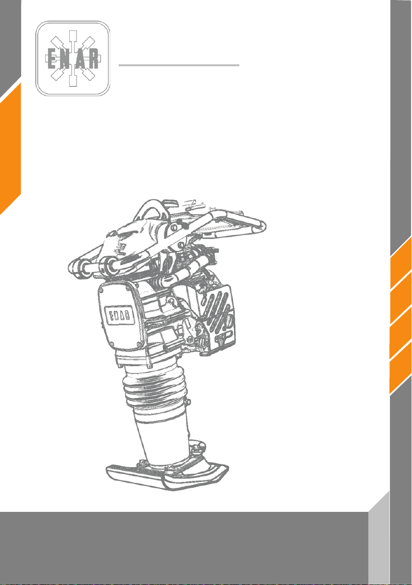
ENARCO, S.A.
de
STAMPFERS
PH60 - PH70 - PH80
Gebrauchsanweisungen
Page 56

1
de
PH60, PH70, PH80
INHALSVERERZEICHNIS
1 VORWORT 2
2 SICHERHEITSHINW EISE 3
2.1 SICHERHEIT BEIM MASCHINENBETRIEB 3
2.2 SICHERHEIT BEIM MOTORBETRIEB 3
2.3 SICHERHEIT BEIM SERVICE 4
3 FÜR JEDER ARBEIT, WELCHE MASCHINE MUUSEN SIE BENUTZEN? 4
4 AKUSTIK- UND VIBRATIONSMESSUNGEN 5
5 INETRIEBNAHME, BETRIEB UND WARTUNG DER MASCHINE 5
5.1 VOR DER INBETRIEBNAHME 5
5.2 INBETRIEBNAHME 5
STAMPFERS
5.3 ARBEITEN MIT DER MASCHINE 6
5.4 ANHALTEN DES MASCHINE 6
5.5 WARTUNG UND LAGERUNG 7
5.6 STÖRUNGSFINDUNG UND REPARATUR 9
6 IM STÖRUNGSFALL 12
6.1 ANWEISUNGEN ZUR ERSATZTEILBESTELLUNG 12
6.2 ANWEISUNGEN ZUR BEANTRAGUNG DER GEWÄHRLEISTUNG 12
7 PLACAS E INDICATIVOS / PLATES AND INDICATIVES / PLAQUES ET INDICATEURS /
PLATTEN UND KENNZEICHEN 13
8 ESPECIFICACIONES TÉCNICAS / TECHNICAL DATA / SPECIFICATIONS TECHNIQUES /
TECHNISCHE DATEN 14
Page 57

de
2
PH60, PH70, PH80
1 VORWORT
Wir bedanken uns für das Vertrauen, das Sie in die Marke ENAR gesetzt haben.
Um die Eigenschaften und Arbeitsweisen der Rüttelplatte kennen zu lernen, ist es wichtig,
dieses Handbuch zu lesen. Bevor Sie die Arbeit mit der Maschine beginnen oder
Wartungstätigkeiten daran ausführen, müssen Sie die in diesem Handbuch enthaltenen
Sicherheitsanweisungen gelesen und verstanden haben, und sie befolgen.
Sollten Sie das Handbuch verloren haben oder eine weitere Ausgabe benötigen, fordern Sie es
bitte bei ENARCO an oder greifen sie auf das Handbuch im elektronischen Format auf der ENARCO
– Homepage
des Geräts.
Wartung und Reparaturen des Motors empfehlen wir das Bedienungshandbuch des Motors.
Sollten Sie Auskunft über Betrieb oder Wartung dieser Maschine benötigen, wenden Sie sich bitte
telefonisch, per Fax, oder mit einer Anfrage per E-Mail an den ENARCO Kundendienst unter
oder über die Homepage in der Rubrik
http://www.enar.es zu und drucken Sie es aus.
Eine ordnungsgemäße Wartung gewährleistet lange Lebensdauer und ausgezeichnete Leistung
In diesem Handbuch geben wir zwar einige Anweisungen zum Motor gegeben, aber bezüglich
Servicio ENAR
STAMPFERS
Page 58

3
de
PH60, PH70, PH80
!
!
2 SICHERHEITSHINWEISE
2.1 SICHERHEIT BEIM MASCHINENBETRIEB
Durch fehlerhafte Anwendung oder Wartung des Geräts können Gefahrensituationen
entstehen. Lesen Sie und begreifen Sie die Anweisungen in diesem Abschnitt, bevor sie die
Arbeit mit der Maschine beginnen. Der Bediener des Geräts ist dafür verantwortlich, das Gerät
Maschine kennt, um Hinweise, oder wenden Sie sich an ENARCO.
mit Sicherheit bedienen zu können. Im Fall von Fragen, bitten Sie das Personal, das die
• Der Motor wird während des Betriebs sehr heiß. Lassen Sie ihn bitte abkühlen, bevor Sie ihn
berühren.
• Lassen Sie die Maschine niemals unbeaufsichtigt in Betrieb.
• Der Bediener muss Schutzkleidung und Gehörschutz tragen.
• Verhindern Sie den Zugang Ungefugter zum Arbeitsbereich.
• Bevor Sie den Motor starten, stellen Sie bitte sicher, dass Sie bei eventuellen Fehlern wissen,
wie die Maschinen ausgeschaltet wird.
• Stoppen Sie die Maschine vor ihrem Transport.
• Versuchen Sie nicht, das Gerät ohne Hilfe hochzuheben. Bitten Sie um Hilfe oder benutzen
Sie ein Hubgerät, indem Sie den im Plattenkäfig eingebauten Griff zum Anheben dafür
verwenden.
• Verwenden Sie das Gerät nicht, wenn es sich nicht in gutem Zustand befindet.
• Lagern Sie das Gerät an einem sauberen und trockenen Ort, wenn es nicht gebraucht wird.
STAMPFERS
2.2 SICHERHEIT BEIM MOTORBETRIEB
Auf Grund ihrer hohen Entzündlichkeit sind die Kraftstoffe besonders gefährlich. Ihre fehlerhafte
Verwendung kann zu schweren Personen- und Sachschäden führen. Folgende
Sicherheitsregeln sind immer einzuhalten:
• Betreiben Sie das Gerät nicht innerhalb eines Gebäudes oder in geschlossenen Räumen,
wenn keine angemessene Belüftung vorhanden ist. Andernfalls könnte eine
Kohlenmonoxydvergiftung mit Bewusstseinsverlust und eventuellen tödlichen Folgen eintreten.
• Bevor der Kraftstofftank gefüllt wird, muss der Motor gestoppt und ein paar Minuten lang
abkühlen gelassen werden.
• Während des Maschinenbetriebs und Auftankens ist Rauchen verboten.
• Füllen Sie den Tank nicht in der Nähe von offenem Feuer und tanken Sie einem gut belüfteten
Bereich.
• Tauschen Sie den Kraftstofftank sofort aus, wenn er undicht ist. Er könnte andernfalls eine
Explosion verursachen.
• Wird beim Tanken Kraftstoff verschüttet, muss er mit Sand aufgesaugt werden. Ziehen Sie
sich um, wenn Kraftstoff auf ihre Kleidung gelangt ist.
• Stellen Sie sicher, dass der Kraftstofftank nach dem Tanken wieder gut verschlossen ist.
• Prüfen Sie nach, ob Leitungen und Kraftstofftank weder Risse noch Lecks aufweisen.
Page 59
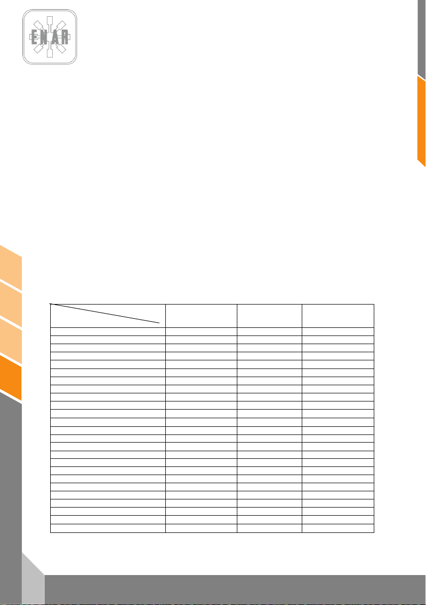
de
4
PH60, PH70, PH80
ARBEIT
Unreversierbare
Platten
Nachbearbeitung
#
Tiefbau
+
Wegenbau
#
Sportplatz
#
Vorbereitung
+ # #
Beistand Brucke und Rampen
+ + #
Eisenbahnbau
+ + #
Betonmasse
# +
Strasse bauen
+ # +
Abflussrohr bauen
+ +
Verdichten Abflussrohr
+ +
Lochwartung (Leistung)
# +
Leistung, Kabel
# # +
Abraum
Kieselstein
+ + +
Sand oder Wolkanischer Staub
+ + #
Boden gemischt
+ # +
Schlamm
+ +
Tonerde
+ +
Schichten 0-25 cm
+ + +
Schichten 20-40 cm
+ +
warme Mischung/ Asphalt
# + #
Kalte Mischung / Asphalt
# + #
Mischung 40-100 mm / Asphalt
+ # +
Mischung 25-60 mm / Asphalt
# +
2.3 SICHERHEIT BEIM SERVICE
• Reinigen oder prüfen Sie das Gerät nicht, während es in Betrieb ist.
• Starten Sie den Motor nicht, wenn der Zylinder überschwemmt ist und bei den Benzinmotoren
die Zündkerze ausgebaut wurde.
• Prüfen Sie nicht, ob die Zündkerze Funken abgibt, wenn der Zylinder mit Benzin
überschwemmt ist oder Benzindämpfe vorhanden sind.
• Verwenden Sie keine Lösemittel oder Kraftstoffe zur Gerätereinigung, insbesondere nicht in
geschlossenen Räumen.
• Halten Sie den Bereich in der Nähe des Schalldämpfers frei von brennbaren Stoffen.
• Bevor in Geräten mit Benzinmotor Servicetätigkeiten ausgeführt werden, muss die Zündkerze
ausgebaut werden, um einen unvorhergesehenen Motorstart zu vermeiden.
• Die Verwendung des Geräts in explosionsgefährdeten Umgebungen ist verboten. Der
Kraftstofftank muss dicht abschließen. Bei langen Transporten ist es sehr empfehlenswert, den
Kraftstofftank des Motors zu entleeren.
• Das Transportzubehör wurde nicht konstruiert, um darauf die Platte abzustellen, sondern soll
nur zum Verfahren des Geräts verwendet werden.
3 FÜR JEDER ARBEIT, WELCHE MASCHINE MUUSEN SIE
BENUTZEN?
MODELL
reversierbare
Platten
# Benutzt + Empfohlen
Stampfer
STAMPFERS
Page 60
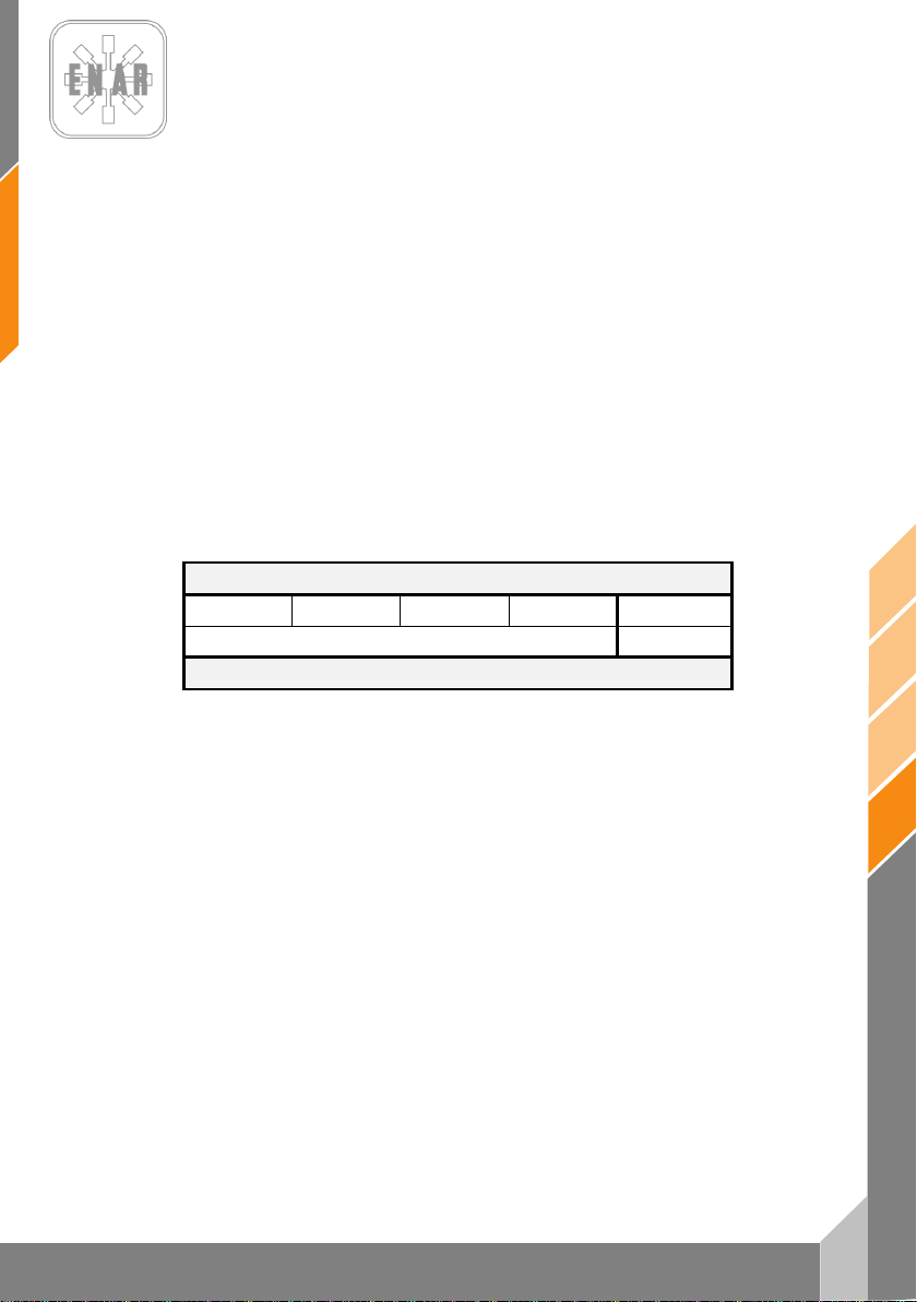
60,
70, P
4 AKUSTIK- UND VIBRATIONSMESSUNGEN
- Lautstärke nach EN 500-4: LWA 106 dB(A)
- Schalldruckpegel nach EN 500-4: L
- Tatsächlicher axialer und gemittelter Beschleunigungswert nach EN 500-4: Ahv
96 dB(A)
pA
6,8 m/s
2
5 INETRIEBNAHME, BETRIEB UND WARTUNG DER MASCHINE
5.1 VOR DER INBETRIEBNAHME
5.1.1.- Die Mechanik dieser Maschine wird durch ein Ölbad geschmiert. Überprüfen Sie den Ölstand
in dem Schauglas, der sich in dem hinteren Teil unterhalb des Balgs befindet. Wenn in dem
Schauglas kein Öl zu sehen ist, gießen Sie welches nach, bis das Schauglas zur Hälfte bedeckt ist.
5.1.2.- Füllen Sie den Kraftstofftank mit dem für den Motor ihrer Maschine geeigneten Kraftstoff, den
sie der Tabelle entnehmen können.
MOTORMODELL
HONDA GX120 HONDA GX100 ROBIN ER12 ROBIN EH12 YANMAR L48
BLEIFREIES BENZIN DIESEL
KRAFTSTOFFTYP
Filtern Sie beim Auffüllen des Tanks den Kraftstof durch ein Sieb. Vergessen Sie nicht, den
Tankverschluss wieder aufzustecken und ihn festzuschrauben, da das Arbeiten ohne ihn gefährlich
ist. Durch die Vibration könnte Kraftstoff austreten, sich entzünden und zu brennen anfangen.
5.1.3. Überprüfen sie die Spannung aller Bolzen, Stifte, Muttern oder schraubbaren Teile. Eine
Schraube, die sich durch Vibration gelöst hat, kann ein unerwartetes ernsthaftes Problem
verursachen. Vergewissern Sie sich, dass alle schraubbaren Teile fest angezogen sind.
5.1.4. Beseitigen Sie allen Schmutz und Staub. Reinigen Sie besonders den am Rücklaufanlasser
und am Fuß anliegenden Bereich.
de
5.2 INBETRIEBNAHME
STAMPFERS
5.2.1.- Öffnen Sie den Kraftstoffhahn, indem Sie den Hebel nach unten legen. Schließen Sie den
Luftregulierhebel und legen sie den Hebel des Luftdrosselventils in halboffene Stellung. Um den
Motor kalt zu starten, drehen Sie den Luftregulierhebel bis zur Schließstellung. Wenn der Motor
warm ist, sollte der Luftregulierhebel halb oder vollständig geöffnet sein. Wenn sich das Anlassen
des Motors als schwierig erweist, vergewissern Sie sich, dass der Luftregulierhebel halboffen steht,
um zu vermeiden, dass der Vergaser wegen Kraftstoffüberschuss aussetzt.
5.2.2.- Ziehen Sie beim Anlassen die Anlasserschnur nicht bis zur maximalen Länge heraus, da die
Rückholfeder beschädigt werden könnte. Lassen Sie die Schnur nicht schlagartig los, um das
Anlassen zu wiederholen, nachdem der Motor schon angelaufen ist. Behalten Sie den Griff in der
Hand und geben Sie langsam nach, bis sich die Schnur vollständig aufgerollt hat.
PH
PH
H80
5
Page 61

de
6
PH60, PH70, PH80
5.3 ARBEITEN MIT DER MASCHINE
5.3.1.- Öffnen Sie nach dem Starten des Motors nach und nach den Luftregulierhebel, bis er
vollständig geöffnet ist. Lassen Sie den Motor bei Mindestgeschwindikeit 3 – 5 Minuten lang warm
laufen. Das Warmlaufenlassen des Motors bei niedriger Umdrehungszahl ist besonders in den
Kälteperioden wichtig. Während der Motor warm läuft, machen Sie eine umfassende Überprüfung
der Maschine, um etwaige Anomalien aufzufinden.
5.3.2.- Der Kolben beginnt zu arbeiten, wenn man den Schleuderhebel schnell eine Vierteldrehung
weit dreht. Wenn der Hebel nur langsam gedreht wird, läuft der Stampfer unregelmäßig und es
können die Kupplung, die Feder oder der Rammfuß desselben beschädigt werden.
5.3.3.- Sobald der Stampfer läuft, stellen Sie die Vibrationsbewegung auf die für die Eigenarten des
Bodens angemessene ein, indem Sie diese leicht mit dem Schleuderhebel regulieren. Dieser
Stampfer wurde so entwickelt, dass sein Fuß bei einer Umdrehungszahl von 3.600 – 4.000 u/min
600 bis 700 mal pro Minute die Bodenoberfläche rammt. Auf diese Weise wird die größte Wirkung
erreicht. Eine unnötige Steigerung der Motorgeschwindigkeit verursacht keine Erhöhung der
Verdichtungskraft, sondern die daraus resultierende Resonanz bewirkt nur, dass die
Verdichtungskraft sinkt, während gleichzeitig die Maschine beschädigt wird.
5.3.4.- Da bei kaltem Wetter das Öl in der Maschine dickflüssig ist, ist der Widerstand in dem
Wechselteil höher und verursacht in dem Verdichterstampfer eine etwas unregelmäßige Bewegung.
Deshalb empfiehlt es sich, vor dem Arbeiten die Maschine warm laufen zu lassen und den
Schleuderhebel wiederholt zwischen den Positionen 0 – ¼ hin und her zu drehen.
5.3.5. Die Oberfläche des Rammfußes ist mit einer thermisch behandelten Platte überzogen.
Trotzdem ist für das Verdichten von Rundkanten eine Füllung von Feinmaterial wie beispielsweise
Sand ratsam, sodass das hintere Ende der flachen Oberfläche des Rammfußes Bodenkontakt hat.
5.3.6. Der Verdichterstampfer wurde so entwickelt, dass er sich mit der Vibration gleichzeitig
vorwärtsbewegt. Um eine schnellere Vorwärtsbewegung zu erreichen, heben Sie die Maschine an,
indem Sie diese leicht nach hinten ziehen, sodass das hintere Ende der flachen Oberfläche des
Rammfußes Bodenkontakt hat.
5.3.7 Um die Arbeit zu unterbrechen und sie umgekehrt wieder aufzunehmen, bewegen Sie
schnell den Schleuderhebel von der Stellung ¼ zur Nullposition.
5.4 ANHALTEN DES MASCHINE
5.4.1.- Um die Arbeit zu unterbrechen und sie umgekehrt wieder aufzunehmen, bewegen Sie schnell
den Schleuderhebel von der Stellung ¼ zur Nullposition.
5.4.2.- Bevor dem Motor anzuhalten, lassen Sie mit abgestelltem Motor wahrend 2-3 Minuten
drehen. Dann drücken Sie den Schalter bis dem Anhalten der Maschine.
5.4.3.- Wenn sie das Wassertank angewendet haben, machen Sie das Wassertank zu.
STAMPFERS
Page 62
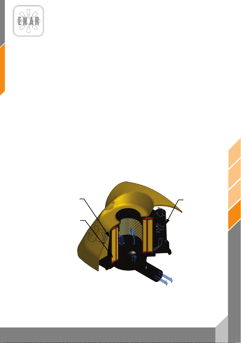
7
de
PH60, PH70, PH80
2. STUFE
1. STUFE
3. STUFE
5.5 WARTUNG UND LAGERUNG
5.5.1. Bevor Sie jegliche Wartungsarbeiten ausführen, SCHALTEN SIE DEN MOTOR AB.
5.5.2. Tägliche Wartungsarbeiten:
Beseitigen Sie an der ganzen Maschine allen Schmutz, Staub oder Ölrückstände.
Überprüfen Sie den Luftfilter und reinigen Sie ihn, wenn nötig. Ziehen Sie an allen
Stellen, an denen Öl austritt, die Schrauben nach und vergewissern Sie sich, dass alle
5.5.3. Wöchentliche Wartungsarbeiten (Alle 50 Stunden):
5.5.4. Wartungstätigkeit alle vierzehn Tage (alle 100 Betriebsstunden) oder nach Anzeige des
anderen Teile fest angezogen sind.
Entfernen Sie den Deckel des Luftfilters und reinigen Sie das Innenelement mit einer
neutralen Reinigungslösung. Nach dem Trocknen tragen Sie ein Kraftstoffgemisch aus
Benzin und Öl auf (wenn möglich, verwenden Sie den im Gebrauch befindlichen
Kraftstoff) und schütteln Sie das Innenelement gut. Anschließend drücken Sie leicht das
erste Außenelement (den Schwamm) aus und legen es auf das zweite Innenelement, um
es zu montieren.
Stellen Sie an der Zündkerze den Elektrodenabstand auf einen W ert von 0,7 – 0,8 mm ein.
Entfernen Sie den Deckel der Einfüllöffnung für das Öl (sie befindet sich oberhalb des
Schauglases für den Ölstand) und legen Sie die Maschine so auf die Seite, dass die
Einfüllöffnung unten liegt und das Öl vollständig auslaufen kann.
Stellen Sie die Maschine wieder hin und gießen Sie durch einen Einfülltrichter in
dasselbe Loch so viel neues Öl, bis sie den Ölstand im Schauglas sehen können.
Der erste Ölwechsel wird nach 50 Betriebsstunden durchgeführt und ab dem zweiten
Ölwechsel alle 300 Arbeitsstunden.
Wartungssensors am Luftfilter (falls vorhanden):
STAMPFERS
FILTERSTUFEN
Page 63
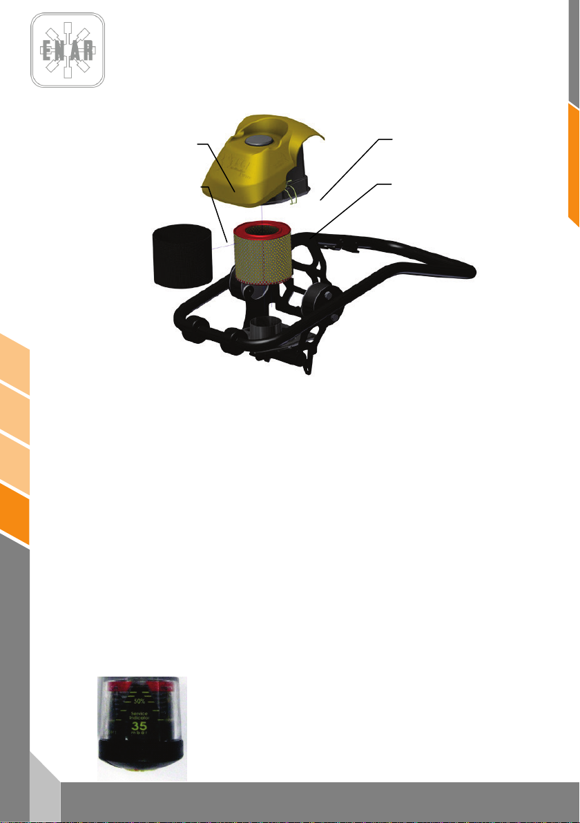
de
8
PH60, PH70, PH80
3
4
1
2
Lösen Sie die Befestigungsklammern (2). Entfernen Sie den Deckel vom Luftfilter (1). Entnehmen
Sie die zweite (3, Schwamm) und dritte (4, Kartusche) Filterstufe. Schütteln Sie die dritte Stufe und
blasen Sie sie mit Druckluft von innen nach außen aus.Reinigen Sie die zweite Filterstufe mit einer
neutralen Reinigungslösung. Nachdem sie getrocknet ist, tragen Sie bitte eine Treibstoffmischung
aus Benzin und Öl auf und schütteln Sie sie gut. Drücken Sie im Anschluss das externe
Primärfilterelement (Schwamm) leicht aus und legen Sie es auf die dritte Stufe zum Einbauen.
Bauen Sie die Baugruppe in das Innengehäuse des Filters ein, bringen Sie das Obergehäuse an
und schließen Sie es mit den Befestigungsklammern.
5.5.5. Monatliche Wartungsarbeiten (Alle 250 Stunden):
Reinigen Sie den Innenraum des Kraftstofftanks. Reinigen Sie sorgfältig alle Teile der
Maschine und ziehen Sie von Neuem die Bolzen, Stifte und Muttern nach, wenn es
5.5.6. Richtige Lagerung:
5.5.7. Wartung mit Luftfiltersensor
erforderlich sein sollte.
Für eine längere Lagerung nach einer beendeten Arbeit entfernen Sie allen Kraftstoff aus
dem Tank, dem Tankrohr und dem Vergaser.
Entfernen Sie die Zündkerze, gießen Sie einige Tropfen Öl in den Zylinder und bewegen
Sie den Motor von Hand einige Umdrehungen lang, damit sich das Öl überall verteilen
kann. Für die Außenreinigung benutzen Sie einen mit Öl angefeuchteten Lappen.
Lagern Sie die Maschine an einem staubfreien und trockenen Ort. Verwenden Sie einen
Überzug und vermeiden Sie direkte Sonneneinstrahlung.
Wenn ein Sensor der Luftfilterbelastung vorhanden ist, verschiebt er sich mit
der Verschmutzung des gelben Körpers bis zum roten Anzeigebereich des
Servicebedarfs. Führen Sie die Filterwartung nach Angaben im Punkt 5.5.4
durch und starten Sie den Sensor neu, indem sie den gelben Filterknopf
drücken.
STAMPFERS
Page 64

9
de
PH60, PH70, PH80
5.5.8. Tachometerbetrieb
Mit Dieselmotor:
Servicealarmanzeige SVC2: Nach 50 Betriebsstunden zeigt der Tachometer den SCV2-Alarm an.
Führen Sie bitte die vorgeschriebene Wartungstätigkeit aus. Um den Zähler neuzustarten, drücken
Sie bitte 3 x “RESET” und halten Sie den Knopf gedrückt, bis auf dem Display Reset erscheint.
Servicealarmanzeige SVC: Nach 250 Betriebsstunden zeigt der Tachometer den SVC-Alarm an.
Führen Sie bitte die vorgeschriebene Wartungstätigkeit aus. Um den Zähler neuzustarten, drücken
Sie bitte 2 x “RESET” und halten Sie den Knopf gedrückt, bis auf dem Display Reset erscheint.
Bei stillstehendem Motor zeigt das Display die Gesamtbetriebszeit an.
Diese Zeit kann nicht auf null gestellt werden. Bei laufendem Motor zeigt
das Display die Umdrehungen pro Minute an.
Um die Teilbetriebsdauer sehen zu können, müssen Sie den "SELECT"Knopf drücken. Um die Teilbetriebsdauer auf null zu stellen, müssen Sie
den "SELECT"-Knopf gedrückt halten. Die aktuelle Teilbetriebsdauer
wird angezeigt. Beim Loslassen wird der Zähler auf null gestellt.
5.6 STÖRUNGSFINDUNG UND REPARATUR
BENZIN MOTOR
Es läuft nicht
- Der Tank is voll aberdie Zundkerze läuft nicht
• Spannung in der Kabel
beschädigte Zundkerze
Bürsten in der Zundkerze
Stromschläge wegen schlechter Isolierung
unregelmässige Entfernung zwischen den Elektroden
• Keine Spannung in der Kable
Stromschläge in die Schalter
beschädigte Zundkerze
Absonderung des Kondensatores unregelmässig
Zundkerze ist gebrochen
• Unregelmässig Kompression
unregelmässige Benzin
Wasser und Staub in der Maschine
Lustfilter wechsefen
- Benzin in der Vergaser
• Unregelmässig Verdichtung
Eingangventile defekt
Zylinder Ring or Stramfer Ring benutz
Zylinderkopf der Zundkerze unregelmässig
Zylinderkopfsichtung defekt
Kupplung defekt
• Die Kupplung wird und Ursachen blockiert, die der Zerhacker beim
Versuchen zu beginnen dreht
• Benzin Tank leer
Tank leer
Benzin Schlüssel nicht richtig offnet
Benzin filter verstopfen
Eingangventile des Tankes verstopfen
Luft im Sclauch
Feder pumpe des Vergasers drücken
STAMPFERS
Page 65

de
10
PH60, PH70, PH80
Keine Leistung:
- Unrichtige Leistung
• Richtige Verdichtung und keine Probleme um die Maschine zu läufen
Luftfilter verschliesst
Bürsten im Zylinder
Benzin in dem Karburator reicht nicht
• Nicht ausreichende Kompression
(cf "Unregelmässige Verdichtung")
• Richtige Verdichtung aber Problem am Starten
Wasser im Ben zin
Zundkerze dreckig
Anlassen Spulung defekt
Anlassen defekt
• Ol Uberschuss
- Der Motor läuft heiss
• Bürsten im Verbrennungraum
• Zundkerze heizt nicht genug
• Verripung dreckig
- Die Drehgeschwindigkeit schwankt
• Einstellen des Motores defekt
• Gas Feder defekt
• Benzin mangel
• Luft im Schlauch
Start mit Seil rückgangsystem defekt
- Staub
- Spring defekt
DIESELMOTOR (luftgekühlt)
Starten defekt
A.- Unregelmässig Kompression
• Keine Kompression
Eingangventile defekt.
Dekompression System defekt.
• Sehr schwache Kompression
Eingangventile defekt.
Stampfer Ring defekt
Zylinder defekt.
Zylinderkopf defekt.
B.- Unregelmässige Injektion im Verbrennungraum
Injektion defekt.
• Benzin Mangel unregelmässig.
Luft in der Maschine.
Olfilter defekt.
Ol Uberschuss.
Luft im Schlauch.
• Keine Injektion im Verbrennungraum.
Zylinderkopfsichtung defekt.
Injektion defekt.
Injektion Weise defekt.
STAMPFERS
Page 66

11
de
PH60, PH70, PH80
• Benzin Tank leer.
• Luft oder Staub
C.- Ol system und richtige Kompression aber es läuft nicht
• Es läuft nicht.
-Starten defekt.
-Hoch dickflüssigkeit des Ol.
-Luft im Schlauch.
Endleistung unregelmassig. Unregelmassige Kompression.:
• der Motor läuft heiss und Eingangventile defekt.
Riffelung mit Staub.
Wasser im Benzin
Bürsten im Verbrennungraum.
Reglierung defekt.
Ubergewicht.
Injektionregulierung defekt.
Injektion defekt.
• Unregelmassige Umdrehungen.
Kontakt zwischen die Regulierung und das Handgriff defekt.
Einstellen des Motores defekt.
Bohrwinde defeckt.
• Start mit Seil rückgang system defekt
Eingangventile defekt.
Ubergewicht.
• Starten defekt.
Ritzel, Zylinder oder Ring defekt.
Injektion defekt.
Stampfer Ring defekt
Regelierung des Zylinderkopf defekt.
Eingangventile defekt.
Kupplumg defekt.
• Hoch Benzin BeKonsommation.
benzinrohrbruch.
Komponenten des Luftfilter defeky.
Staub im Benzin.
Ubergewicht
• Ritzel Ring defekt
Ol defekt
Olwechsel defekt.
Luftfilter defekt oder mit Staub.
• Bruit anormal
Ritzel defekt
• Ol defekt
Komponente der Ritzel defekt
• Der Motor hält nicht an, auch nicht, wenn die Brennstoffversorgung
unterbrochen wird (oder geht in den Schnellgang)
Ol.
Regulierung system defekt.
Feder Pumpen drücken.
STAMPFERS
Page 67

de
12
PH60, PH70, PH80
GEBRAUCH DER MASCHINE
Scnelligkeit defekt
• Die regulierung macht nicht auf die ganze Schnelligkeit des Motores
• Leistung des Motores defekt.
• Kupplung defekt.
• Ganze Ol im Vibrator .
• Inneren Komponenten des Vibratores defekt.
Verlangerung defekt.
• Reglierung defekt.
• Teilen des Accelerator defekt.
• Kupplung defekt.
Keine Verlangerung
• Kupplung defekt.
• Benzin Tank defekt.
• Die Stampfer ist über eine gleite Oberfläsche.
• Uberprüfen eine richtigen Oberfläsche.
6 IM STÖRUNGSFALL
6.1 ANWEISUNGEN ZUR ERSATZTEILBESTELLUNG
1. Auf allen Ersatzteilbestellungen MUSS DIE SACHNUMMER DES TEILS AUS DER
STÜCKLISTE angegeben werden. Es ist auch empfehlenswert, DIE FERTIGUNGSNUMMER
DER MASCHINE anzugeben.
2. Das Typenschild mit den Serien- und Modellnummern befindet sich auf der Unterseite des
Motorunterteils.
3. Geben Sie uns die ordnungsgemäßen Transportanweisungen, inkl. gewünschte Strecke,
sowie Anschrift und vollständigen Namen des Empfängers, an.
4. Senden Sie ohne schriftliche Genehmigung keine Ersatzteile an das Werk zurück. Alle
zulässigen Rücksendungen müssen frei erfolgen.
6.2 ANWEISUNGEN ZUR BEANTRAGUNG DER GEWÄHRLEISTUNG
1. Die Gewährleistungsdauer beträgt 1 Jahr ab Maschinenerwerb. Die Gewährleistung deckt
Teile mit Herstellungsfehlern.
2. Unter keinen Umständen deckt die Gewährleistung Störungen aufgrund fehlerhafter
Geräteverwendung.
3. Bei allen Gewährleistungsanträgen IST DIE MASCHINE AN ENARCO, S.A. ODER AN DIE
ZUGELASSENE WERKSTATT mit Angabe des Namens und der vollständigen Anschrift des
Empfängers zu senden.
4. Die Kundendienstabteilung gibt sofort bekannt, ob die Gewährleistung anerkannt wird. Auf
Antrag wird auch ein technischer Bericht gesendet.
5. Geräte, die von Personal manipuliert wurden, das nicht zu ENARCO, S.A. gehört, haben keine
Garantie.
STAMPFERS
Page 68
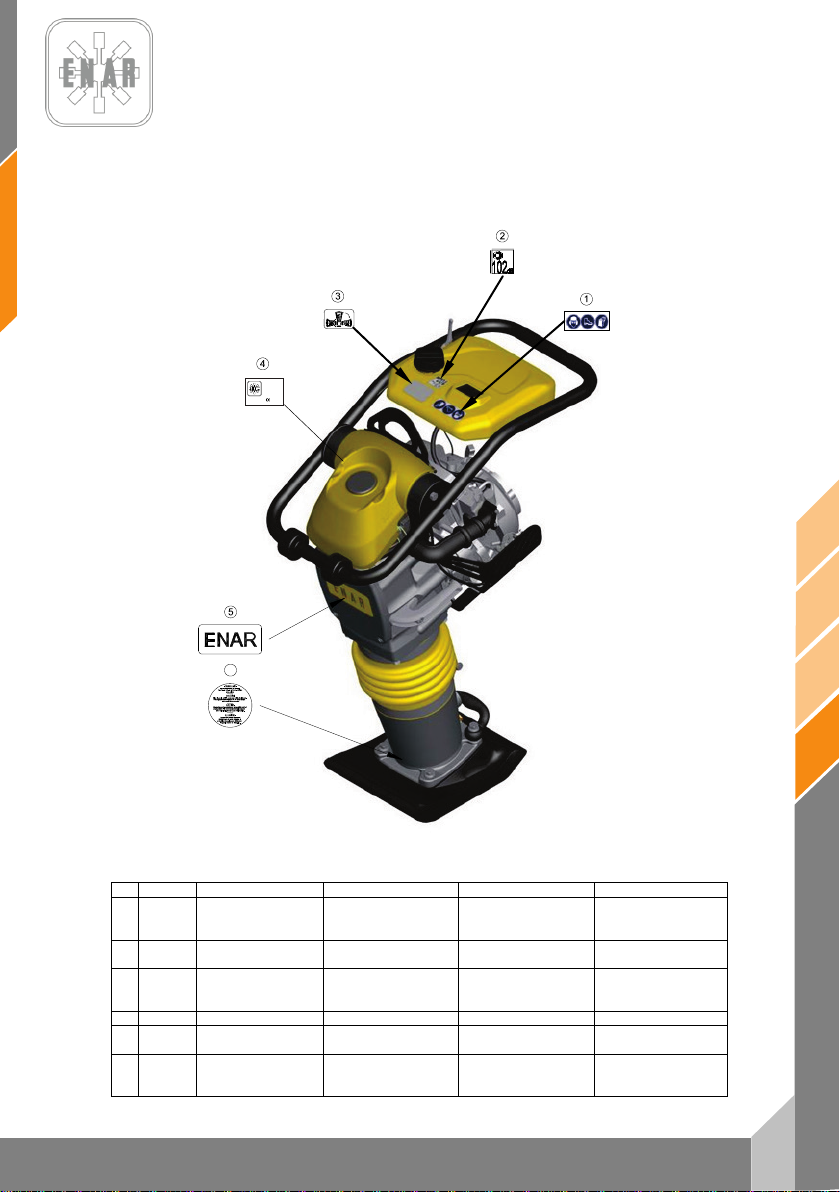
13
de
PH60, PH70, PH80
Nº
REF.
DESCRIPCION
DESCRIPTION
DESIGNATION
BENENNUNG
ADHESIVO
SEGURIDAD
SAFETY
STICKER
ADHÉSIF
SÉCURITÉ
ADHESIVO 104 Dba
ADHESIF
104 Dba
ADHESIVO
DERECHO
4
RC6506
ANAGRAMA ENAR
ENAR STICKER
AUTOCOLANT ENAR
ENAR KLEBSTOFF
ADHESIVO
CARÁCTERÍSTICAS
CHARACTERISTICS
STICKER
AUTOCOLANT
CARACTÉRISTIQUES
MERKMALE
KLEBSTOFF
ADHESIVO
MUELLES
STICKER
SPRINGS
ADHÉSIF
RESSORTS
KLEBSTOFF
SPRUNGFEDER
L
WA
PHX0H
00000000
ENARCO, S.A.
C/ Burtina, 16
2012
50197 Zaragoza
(SPAIN)
6
7 PLACAS E INDICATIVOS / PLATES AND INDICATIVES /
PLAQUES ET INDICATEURS / PLATTEN UND KENNZEICHEN
1 107228
2 107402
3 107284
5
6 107225
PROTECCION
TUMBADO
PRECAUCION
PROTECTION
104 dBA STICKER
PLACE RIGHT SIDE
STICKER
PRECAUTION
PROTECTEUR
ADHÉSIF TOMBÉ À
DROIT
PRECAUTION
STAMPFERS
SCHUTZKLEBSTOFF
104 dBA KLEBSTOFF
RECHTGELIEGENER
KLEBSTOFF
ACHTUNG
Page 69
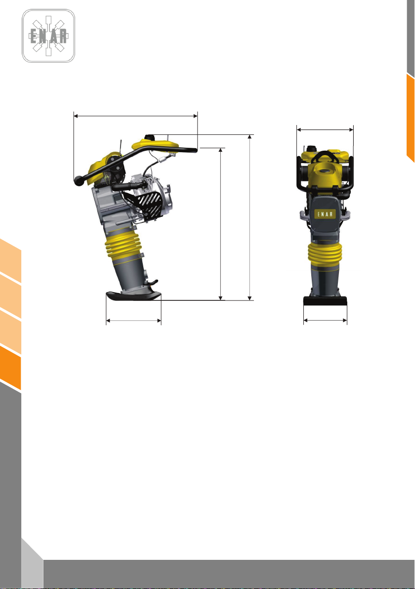
de
14
PH60, PH70, PH80
368
280
332
772
1038
953
8 ESPECIFICACIONES TÉCNICAS / TECHNICAL DATA /
SPECIFICATIONS TECHNIQUES / TECHNISCHE DATEN
STAMPFERS
Page 70
15
de
PH60, PH70, PH80
HONDA
GX100 DKR
ROBIN
ER12
HONDA
GX120 DKR
ROBIN
EH12 D
YANMAR
L48 AE
COMBUSTIBLE (L)
BRENNST OFF (L)
ACEITE MOTOR (L)
MOTORENÖL (L)
POTENC IA NOMINAL
NENNLEISTUNG
BUJÍA
ZÜNDKERZE
ENTREHIERRO
LUFTSPALT
R.P.M.
U-MN
RALE NTÍ
LEERLAUFD REHZAHL
PESO SIN COMBUSTIBLE (Kg)
GEWICHT (Kg)
ELEVACIÓN DEL PISÓN (mm)
SPRINGWEG (mm)
NUMERO DE GOLPES POR MINUTO
EINSCHLAGSFREQUENZ
MOTOR
MOTOR
LUBRICANTE MÁQUINA (L)
MASCHINENOEL (L)
FUEL (L)
COMBUSTIBLE (L)
SIN PLOMO (2.7) SIN PLOMO (2.7) SIN PLOMO (2,7) SIN PLOMO (2,7) GAS-OIL (2,7)
ENGINE OIL (L)
HUILE MOTEUR (L)
NOMINAL POWER
PUISSANCE NOMINALE
SPARK PLUG
BOUGIE
GAP
ENTREFER
R.P.M.
TR-MN
IDLING
RÉGIME RALENTI
SAE 10W/40 (0,6) SAE 10W/40 (0,4) SAE 10W /40 (0,3) SAE 10W/40 (0,4) SAE 10W/40 (0,8)
3 kW (4 HP) 3 kW (4 HP) 3 kW (4 HP) 2,6 kW (3,5 HP) 3,1 kW (4,1 HP)
NGK CR5HSB
DENSO U16FSR-UB
0,6 mm - 0,7 mm 0,6 mm - 0,7 mm 0,7 mm - 0,8 mm 0,6 mm – 0,7 mm
4000 rpm ± 50 4000 rpm ± 50 3500 rpm ± 50 3600 rpm ± 50 3600 rpm ± 50
1700 ±150 r.p.m. 1700 ±150 r.p.m. 1500 ±150 r.p.m. 1600 ±150 r.p.m. 1500 ±150 r.p.m.
NGK CR5HSB
DENSO U16FSR-UB
NGK BP4ES
DENSO W14EP -U
NGK B6ES
CHAMPION N4C
----
----
ESPECIFICACIONES PH60H PH60R PH70H PH70R PH80YD
WEIGHT WITHOUT COMBUSTIBLE (Kg)
POIDS SANS COMBUSTIBLE (Kg)
IMPACT COURSE HEIGHT (mm)
PARCOURS DE FRAPPE (mm)
NUMBER OF BLOWS BY MINUTE
FREQUENCE D’IMPACTS PAR MINUTE
ENGINE
MOTEUR
MACHINE OIL (L)
HUILE POUR MACHINE (L)
68 68 72 72 80
60 65 70 70 70
700 700 700 700 700
HONDA
GX100U
ROBIN
ER12
SAE 30 / ISO 100 (1.8 L.)
ROBIN
GX120U
ROBIN
EH12D
YANMAR
L48AE
STAMPFERS
Page 71
de
16
PH60, PH70, PH80
PAR DE APRIETE
TORQUE
COUPLE
DREHMOMENT
TAMAÑ O DE LLAVE
SPANNER SIZE
DIMENSION DE LA CLEF
GRÖSSE VON DEM
SCHRAUBERSCHLÜSSEL
8.8
10.9
12.9
MÉTRICA
Ft.Lb.
Nm
Ft.Lb.
Nm
Ft.Lb.
Nm
mm
mm
M4
*26
2.9
*36
4.1
*43
4.9 7 3
M5
*
53
6.0 6 8.5 7 10 8 4
M6 7 10
10
14
13
17
10
5
M8
18
25
26
35
30
41
13
6
M10
36
49
51
69
61
83
17
8
M12
63
86
88
120
107
145
19
10
M14
99
135
140
190
169
230
22
12
M16
155
210
217
295
262
355
24
14
* = In.Lb. 1 Ft.Lb. = 1.357 Nm 1 Inch = 25.4 mm
TIPO
TYPE
TYPE
TYP
COLOR
COLOR
COLEUR
FARBE
USO
USE
USAGE
GEBRAUCH
Nº PIEZA/TAMAÑO
PARTNUMBER/SIZE
Nº PIÈCE/DIMENSION
TEILNUMMER/GRÄSSE
Morado
Resistencia baja, para fijar ro scas menores a M36.Resiste
desde -54º a 149ºC.
Purple
Low strength, for locking threads smaller than M36.Temp.
Range –54º to 149ºC.
Violette
Peu de resistence pour fixer des filets plus petits que la M36.
Elle resiste de –54º jusqu’à 149ºC.
Loctite 222
Hernon 420
Omnifit 1150 (50M)
Dunkelviolett
Niedrieger widerstandskraft, um Gewinde kleiner als M36 zu
befestigen. Das widersteht von –54º bis 149ºC.
124151 – 10 ml
Azul
Resistencia media, para fijar roscas m ayores a M36.Resiste
desde -54º a 149º C.
Blue
Medium strength, for locking threads larger than M3 6.Temp.
Range –54º to 149ºC
Bleue
Resistence moyenne pour f ixe r des filets jusqu’â M36. Elle
resiste de –54º jusqu’â 149 ºC.
Loctite 243
Hernon 423
Omnifit 1350 (100M)
Blau
Medium widerstandskraft , um grösser als M36 Gewinde zu
befestigen. Das widersteht von 54º bis 149ºC.
124152 – 0.5 ml
124155 – 50ml
Blanco Sellador de tuberías con Teflón. Resiste desde -54º a 149º C.
White Pipe sealant with Teflon. Temp. Range –54º to 149º C.
Blanque
Colle de tuyanterie avec teflon. Elle resiste de –54º jusqu’à
149ºC.
Loctite 592
Hernon 920
Omnifit 790
Weis
Klebstoff mit teflon für Rohrleitungen. Das widerstehr von –54º
bis 149ºC.
6 ml
50 ml
Transparente Adhesivo estructural para metal. Resiste desde -54º a 82º C.
Clear Instant adhesive for metal. Temp. Range –54º to 82º C.
Transparente Colle instantanée pour metal. Elle resiste de –54º jusqu’à 149ºC
Loctite 495
Deurchsichtig Sofortiger klebstoff für metal. Das widersteht von –54º bis 82ºC
124156 – 1 oz.
Verde
Producto anaeróbico de retención de alta resistencia, tolerante
al aceite.
Green
High resistant product, wich doesn´t need air to react and bears
the oil.
Verte
Producte anaérobie de rétention d’haute resistence, tolérant au
huile.
Loctite 601
Grün
Stoff von grösser widerstandskraft, der ohne sauerstoff reagiert
und das öl zulässt.
124154 – 6 oz.
STAMPFERS
Page 72
CERTIFICADO DE CONFORMIDAD
CONFORMITY CERTIFICATE ~ CERTIFICAT DE CONFORMITÉ
INSTEMMING VERKLARING ~ KONFORMITÄTS BESCHEINIGUNG
KONFORMITETS BEVIS ~ CERTIFICATO DE CONFORMIDADE ~ CERTIFICATO DI CONFORMITA'
ATITIKTIES DEKLARACIJA ~ CERTYFIKAT ZGODNOŚCI ~ СЕРТИФИКАТ СООТВЕТСТВИЯ
CERTIFICAT DE CONFORMITATE~ СЕРТИФИКАТ ЗА СЪОТВЕТСТВИЕ
certifica que la máquina especificada
hereby certify that the equipment specified bellow ~ atteste que le equipment
verklaart hierbij dat onderstaand gespecificeerde ~ bescheinigt, da
bekræfter, at følgende maskine ~ certifica que o equipamento specificaçao
certifica che la macchina specificata ~ šiuo sertifikatu patvirtina, kad žemiau nurodytas prietaisas, t.y.
Zaświadcza, że wyszczególniona maszyna ~ Подтверждает, что нижеописанная машина
Certifica si declara ca echipamentul mentionat mai jos~ Потвърждаваме, че оборудването, описано по-долу
TIPO DE MAQUINA..................................................................................... Pison Compactador
TYPE~TYPE~TYPE~TYP~TYPE~TIPO~TIPO~TIPAS~TYP~ТИП~TIP~ТИП Tamping Rammer / pilonneuse / Stampfer
MODELO.....................................................................................................PH
MODEL~MODÈLE~MODEL~MODEL~MODEL~MODELO
MODELLO MODELIS~MODEL~МОДЕЛЬ~MODEL~МОДЕЛ
CODIGO...................................................................................................... PH60*, PH70*, PH80*
CODE~CODE~CODE~CODE~CODE~CODIGO~CODICE~KODAS~KOD
КОД~ COD ~ КОД
in overeenstemming met de voldenge voorschriften gefabriceerd is ~ in übereinstimmung mit folgenden richtlinien hergestellt worden ist
Potencia acústica medida (LWA)
Gemessene Schalleistung (LWA)
Puissance acoustique mesurée (LWA)
Measured acoustic power (LWA)
Potência acústica medida (LWA)
Moc akustyczna srednia (LWA)
RESPONSABLE DOCUMENTACIÓN TÉCNICA………. Jesus Tabuenca (ENARCO, S.A. Burtina, 16, 50197 Zaragoza
Technical documentation responsible ~ Responsable of the Documentation Technnique ~ zuständigen technishen Dokumentation
Zaragoza, 01.10.2011
MANUFACTURER:
ENARCO, S.A.
C/Burtina 16
Plat. Logística PLAZA
50197 ZARAGOZA
ha sido fabricada de acuerdo con las siguientes normas
has been manufactured according to the following standards ~ est produit conforme aux dispositions des directives ci-apres
er blevet fremstillet i overenstemmelse med følgende retningslinier ~ é fabricado conforme as seguintes normas
è stata fabbricata secondo le norme vigenti ~ buvo pagamintas laikantis toliau išvardintų standartų
została wyprodukowana zgodnie z następującymi normami ~ Произведена в соответствии со следующими нормами
este fabricat cu respectarea urmatoarelor standarde ~ е производено в съответствие със следните стандарти
2006/42/CE, 2000/14/CE, 2005/88/CE
104
dB (A)
SPAIN
e-mail:
Web:
Tfno.
ENARCO,S.A.
EN 500/1, EN 500/4
Potencia acústica garantizada (LWA)
Garantierte Schalleistung (LWA)
Puissance acoustique garantie (LWA)
Guaranteed acoustic power (LWA)
Potência acústica garantida (LWA)
Moc akustyczna gwarantowana (LWA)
(34) 976 464 090
das Baugerät
β
106
dB (A)
Jose Luis Del Prim
General Manager
ENARCO,S.A.
ENARCO, S.A.
 Loading...