

Page 1
ENARCO, S.A.
es
en
fr
de
Manual de instrucciones
Instruction manual
Manuel d'instructions
Gebrauchsanweisungen
MX–825-1710
AFE
– AFG
– AFD
CONVERTIDORES DE FRECUENCIA
FRECUENCY CONVERTERS
CONVERTISSEURS DE FREQUENCE
FREQUENZ UMFORMER
Page 2

CONVERTIDORES DE FRE CUE NCIA
1
es
AFG, AFD, AFE
ÍNDICE
1 PRÓLOGO 2
2 CARACTERÍSTICAS 3
2.1 CARACTERÍSTICAS DE CONVERTIDORES DE FRECUENCIA 3
2.2 CARACTERÍSTICAS CONVERTIDORES CON MOTOR GASOLINA Y DIESEL 6
3 CONDICIONES DE UTILIZACIÓN 6
3.1 AREA DE TRABAJO 6
3.2 SEGURIDAD ELÉCTRICA 7
3.3 SEGURIDAD PERSONAL 7
3.4 USO DE LA HERRAMIENTA Y CUIDADOS 7
3.5 SERVICIO 8
3.6 REGLAS DE SEGURIDAD ESPECÍFICAS 8
4 OPERACIÓN Y MANTENIMIENTO 9
4.1 PUESTA EN SERVICIO 9
4.2 CONEXION DE LAS AGUJAS VIBRANTES AL CONVERTIDOR 9
4.3 CONEXION DEL CONVERTIDOR A LA RED ELECTRICA 9
4.4 MOTOR DE GASOLINA. 11
4.5 MANTENIMIENTO PERIODICO 11
4.6 MANTENIMIENTO CON MOTOR D E GASOL INA 11
4.7 INSPECCION 12
4.8 ALMACENAMIENTO 12
4.9 TRANSPORTE 12
4.10 MANTENIMIENTO DE LA AGUJA VIBRANTE 12
5 LOCALIZACIÓN DE AVERIAS 12
5.1 CONVERTIDORES ELÉCTRICOS 12
5.2 CONVERTIDORES GASOLINA Y DIESEL 13
6 INSTRUCCIONES PARA SOLICITAR REPUESTOS 13
6.1 INSTRUCCIONES PARA PEDIR REPUESTOS
6.2 INSTRUCCIONES PARA SOLICITAR GARANTÍAS 13
Page 3

CONVERTIDORES DE FRE CUE NCIA
es
2
AFG, AFD, AFE
1 PRÓLOGO
Agradecemos la confianza depositada en la marca ENAR.
Para el máximo aprovechamiento de su equipo de vibración recomendamos que lea y entienda las normas
de seguridad, mantenimie nto y utilización recogidas en este manual de instruc ci one s.
Las piezas defectuosas deben ser reemplazadas inmediatamente para evitar problemas mayores.
El grado de disponibilidad de la máquina aumentará si sigue las indicaciones de este manual.
Para cualquier comentario o sugerencia sobre nuestras máquinas estamos a su total disposición.
Page 4

CONVERTIDORES DE FRE CUE NCIA
3
es
AFG, AFD, AFE
2 CARACTERÍSTICAS
TIPO
Convertidor mecánico:
Está compuesto de parte motor y parte generador con Inducido magnético (sin escobillas)
APLICACIÓN
Transformar la tensión y frecuencia de entrada a una tensión de salida de 42 V trifásica y 200 Hz,
para alimentar las agujas vibrantes con motor interno ENAR M35AF, M5AF, M6AF, M7AF y M8AF.
CABLE DE CONEXIÓN A RED
10 m de longitud equipo estándar , con clavi ja de con ex ión t ipo CE, aislamiento 750V. Otras
POSIBILIDADES DE CONEXIÓN
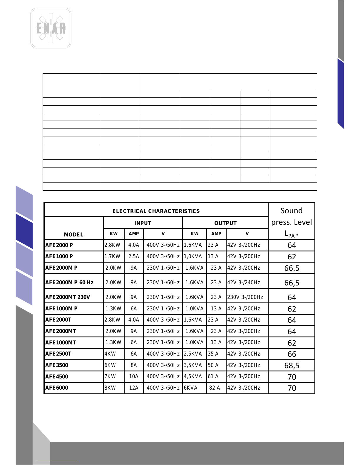
La suma de los consumos en carga de las agujas vibrantes conectadas, no será superior a la
intensidad de salida especificada en la tabla de características eléctricas.
2.1 CARACTERÍSTICAS DE CONVERTIDORES DE FRECUENCIA
MODELO CON CARCASA DE PLASTICO
Trifásico: AFE 2000 P, AFE 1000 P
Monofásico: AFE 2000M P, AFE 1000M P
CARCASA
P, carcasa de PLASTICO DE ALTA RESISTENCIA, con protección contra polvo y salpicaduras y
moto protector.
MODELO CON J AULA DE TUBO
Trifásico: AFE 2000 T, AFE 2500
Monofásico: AFE 2000 MT, AFE 2000MT 230v
CARCASA
T, jaula de ACERO TUBULAR.
MODELO CON CARRO
Trifásico: AFE3 500 , A FE45 00 , A FE60 00
CARCASA
ACERO TUBULAR CON CARRO DE TRANSPORTE CON RUEDAS
Page 5

CONVERTIDORES DE FRE CUE NCIA
es
4
AFG, AFD, AFE
MODEL
KW AMP V KW AMP V
AFE2000 P
2,8KW 4,0A 400V 3-/50Hz 1,6KVA 23 A 42V 3-/200Hz
64
AFE1000 P
1,7KW 2,5A 400V 3-/50Hz 1,0KVA 13 A 42V 3-/200Hz
62
AFE2000M P
2,0KW
9A 230V 1-/50Hz 1,6KVA
23 A
42V 3-/200Hz
64
AFE2000M P 60 Hz
2,0KW 9A 230V 1-/60Hz
1,6KVA 23 A 42V 3-/240Hz
64
AFE2000MT 230V
2,0KW 9A 230V 1-/50Hz
1,6KVA 23 A 230V 3-/200Hz
64
AFE1000M P
1,3KW 6A 230V 1-/50Hz 1,0KVA 13 A 42V 3-/200Hz
62
AFE2000T
2,8KW 4,0A 400V 3-/50Hz 1,6KVA 23 A 42V 3-/200Hz
64
AFE2000MT
2,0KW 9A 230V 1-/50Hz 1,6KVA 23 A 42V 3-/200Hz
64
AFE1000MT
1,3KW 6A 230V 1-/50Hz 1,0KVA 13 A 42V 3-/200Hz
62
AFE2500T
4KW 6A 400V 3-/50Hz 2,5KVA 35 A 42V 3-/200Hz
66
AFE3500
6KW 8A 400V 3-/50Hz 3,5KVA 50 A 42V 3-/200Hz
68,5
AFE4500
7KW 10A 400V 3-/50Hz 4,5KVA
61 A
42V 3-/200Hz
70
AFE6000
8KW 11A 400V 3-/50Hz 6KVA 82 A 42V 3-/200Hz
70
CARACTERISTICAS ELECTRICAS
Presión
Acustica LP
A
*
ENTRADA
SALIDA
* at 1 m of distance of the converter, K =2
Modelos Peso Kg Nº salidas
Possibilidades de conexión agujas vibrantes
ENAR
M38A
M5AF
M6AF
M7AF/M8AF
AFE 2000P
25
2
2
2
1
1
AFE 1000P
15
1
1
1
1
-
AFE 2000MP
27
2
2
2
1
1
AFE 1000MP
17
1
1
1
-
-
AFE 2500T
34 3 5 3 2
2
AFE 3500
70 4 8 4 3
2
AFE 4500
74 4 9 5 4
4
AFE 6000
83
4
10
6
5
4
AFE 1000MT
20
1
1
1
-
-
AFE 2000T
28
2
2
2
1
1
AFE 2000MT
30
2
2
2
1
1
AFE 2000MT 230V
30
2
Este convertidor usa agujas de 230 V
Page 6
CONVERTIDORES DE FRE CUE NCIA
5
es
AFG, AFD, AFE
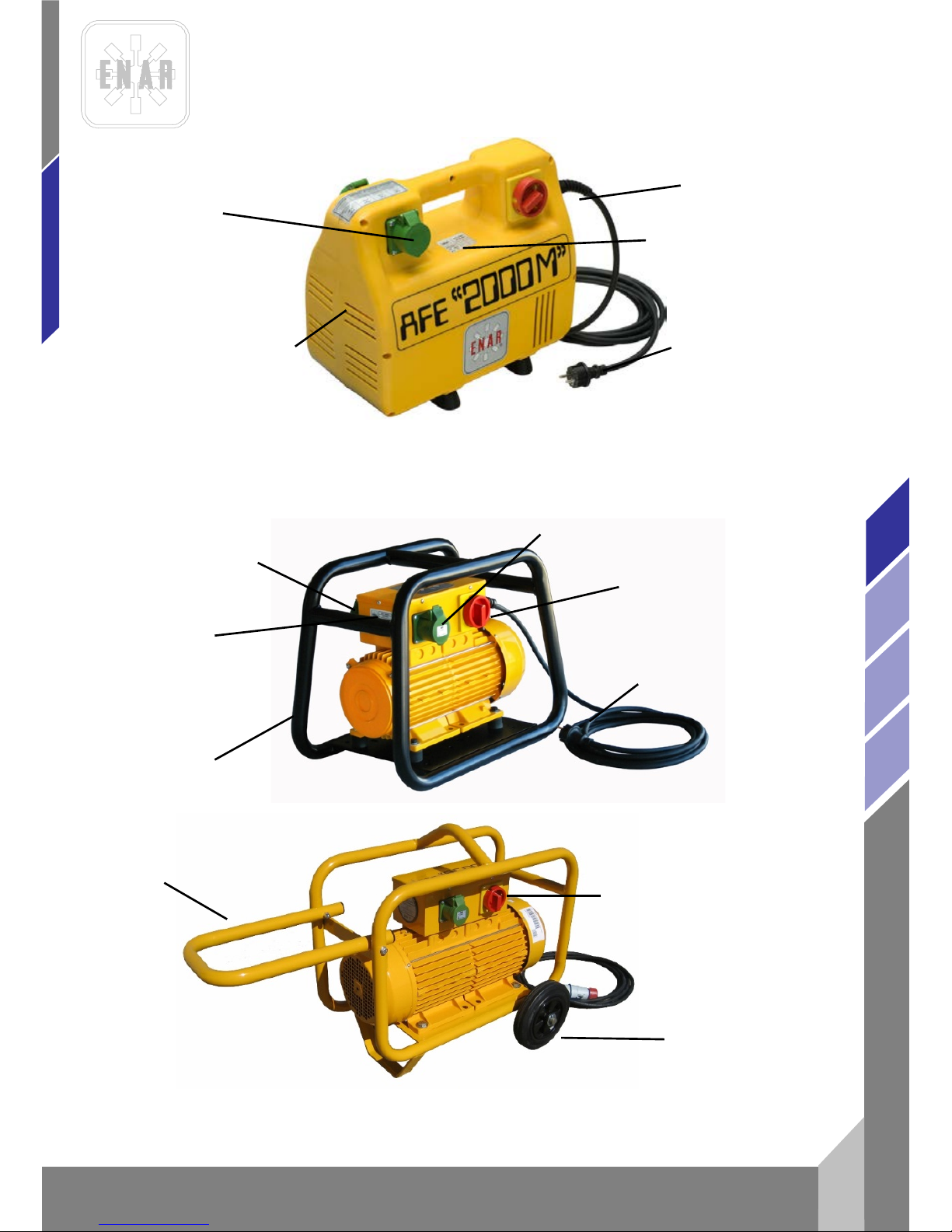
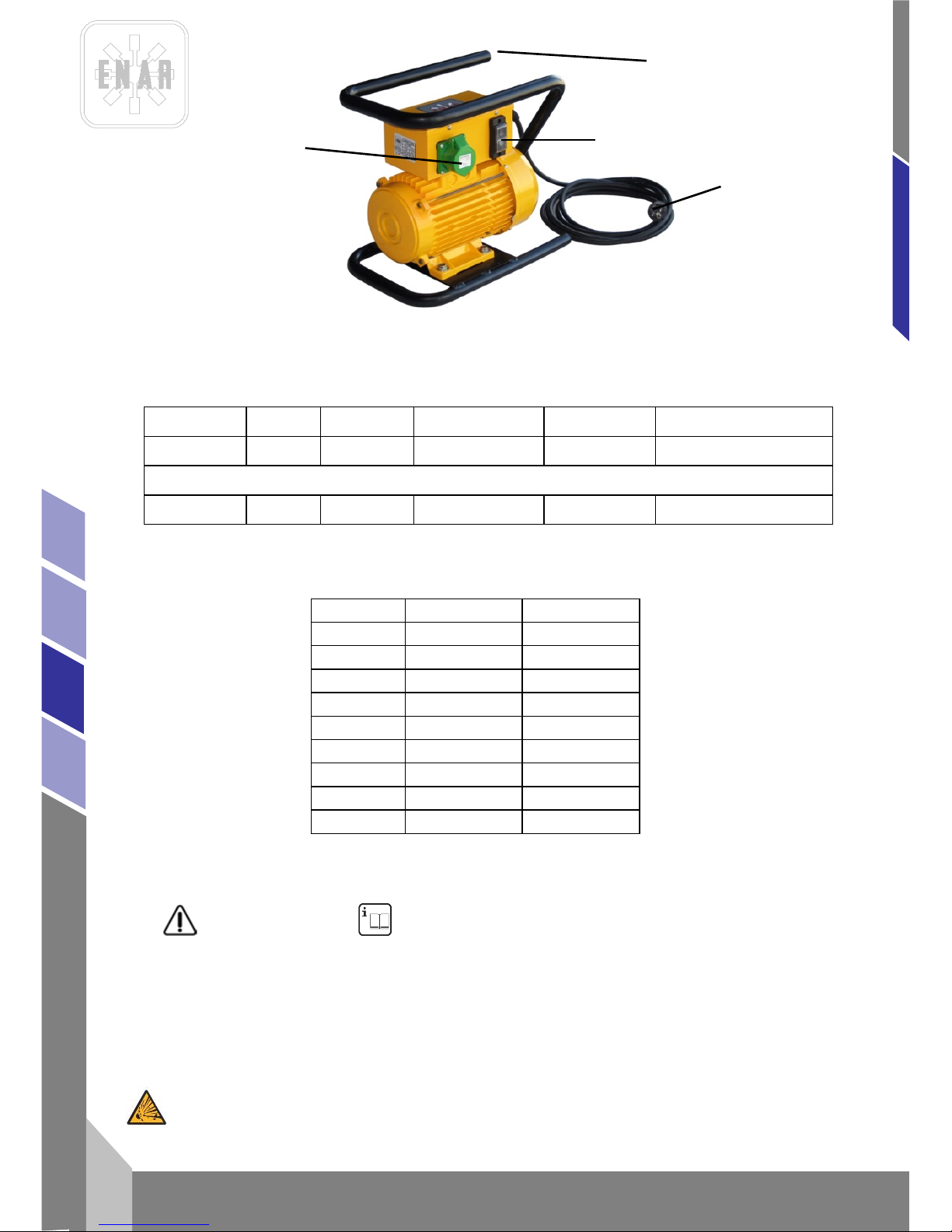
TOMA PARA CONECTAR EL
VIBRADOR 200 Hz < 50 V
INTERRUPTOR (STARTSTOP)
PLACA DE
CARACTERÍSTICAS
CARCASA DE
PLÁSTICO
AFE 2000P, AFE 2000MP, AFE 1000P, AFE 1000MP
PLASTIC HOUSING
CAJA DE
CONEXIONES
PLACA DE
CARACTERÍSTICAS
ACERO TUBULAR
TOMA PARA CONECTAR EL
VIBRADOR 200 Hz < 50 V
INTERRUPTOR (STARTSTOP)
EMCHUFE 2F+E o 3F+E Y
CABLE DE 5 m
AFE 2000T, AFE 2500T, AFE 2000MT, AFE 1000MT TUBULAR FRAME
INTERRUPTOR (STARTSTOP)
AFE 3500, AFE 4500 AND AFE6000 CARRIEGE WHEEL FRAME
ENCHUFE 2F+E o
3F+E Y CABLE DE
5 m
RUEDAS
ASIDERO
Page 7
CONVERTIDORES DE FRE CUE NCIA
es
6
AFG, AFD, AFE
2.2 CARACTERÍSTI CAS CO NVE RTIDORE S CON MOTOR GASOLINA Y DIESEL
MODELO PESO SALIDAS MOTOR GENERADOR AGUJAS
AFGH2000 38Kg 2 5.5HP HONDA 42V / 200HZ
2M5AF / 1M6AF / 1M7AF/
1M8AF
DIESEL
AFDY2000 48Kg 2 4,7 HP YANMAR 42V / 200HZ
2M5AF / 1M6AF / 1M7AF/
1M8AF
MODELO GX 160K1 YANMAR
TIEMPOS 4, 163cc 4, 211c c
POTENCIA 5.5HP/3600rpm 4.7HP/3600rpm
PAR 1.1Kgm/2500rpm 1.25Kgm/2800rpm
RPM 3900rpm 3600rpm
ENCENDIDO TRANSISTOR INJECTION
COMBUST GASOLINA DIESEL
DEPOSITO 3.61 2.51
PESO 15Kg 26Kg
ACEITE 0.61 0.81
3 CONDICIONES DE UTILIZACIÓN
¡ATENCIÓN! LEA Y ENTIENDA TODAS LAS INSTRUCCIONES
3.1 AREA DE T R ABAJO
MANTENGA su zona de tr abajo limpia y bien ilumin ad a.
NO HAGA FUNCIONAR herramientas con motor eléctrico o térmico en atmósferas explosivas, así
como en presencia de líquidos inflamables, gases, o polvo.
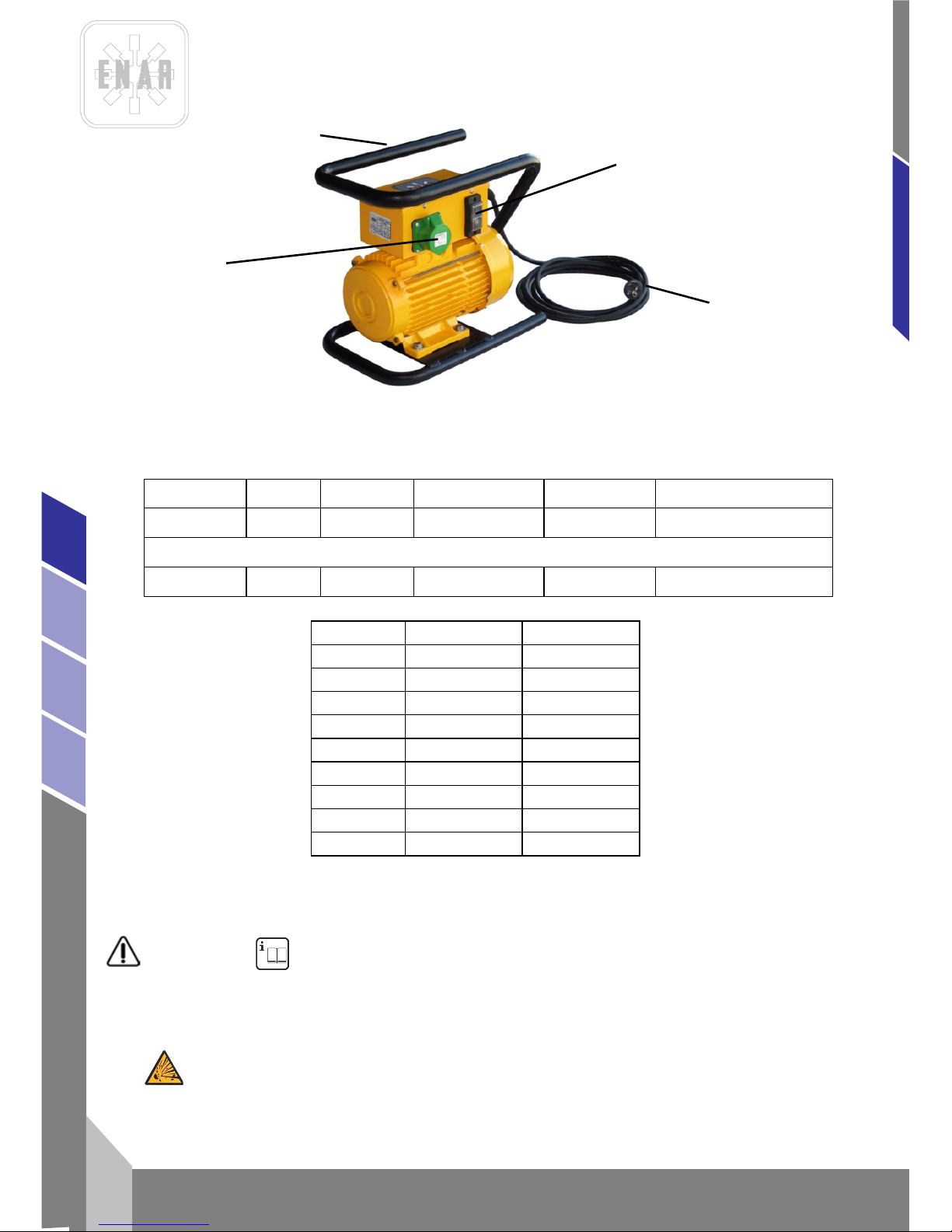
CABLE
ENCHUFE
INTERRUPTOR
ACERO TUBULAR
Page 8
CONVERTIDORES DE FRE CUE NCIA
7
es
AFG, AFD, AFE
MANTENGA a espect ad or es , niño s y visitantes alejados mientras este funcionando la herramienta.
La máquina debe ser solo utilizada por oper arios capacitados de más de 18 años que hayan
leído y entendido el manual de instrucciones.
3.2 SEGURIDAD ELÉCTRICA
Las herramientas conectadas a tierra SE ENCHUFARÁN a una base adecuada y estarán en
concordancia con todos los códigos y decretos.
NO QUITE el terminal de tierra o modifique el enchufe de ninguna forma.
NO UTILICE ningún adaptador de enchufe.
VERIFIQUE con un electricista cualificado si no sabe si la salida está adecuadamente conectada a
tierra.
EVITE que el cuerpo entre en contacto con superficies puestas a tierra, como tuberías, radiadores,
cocinas y frigorífic os .
NO EXPONGA las herramientas a la lluvia y a la humedad.
NO FUERCE el cable de aliment ac ió n.
NO USE NUNCA el cable de alimentación para transportar la herramienta.
NO TIRE del cable de alimentación cuando desenchufe la herramienta.
MANTENGA el cable de alimentación alejado del calor, el aceite, aristas vivas y partes móviles.
REEMPLACE inmediatamente los cables de alimentación dañados.
CUANDO MANEJE una herramienta en exteriores utilice un c a ble de al im ent ac ión para exteriores
o un cable marcado "H07RN-F", "W-A" o "W".
3.3 SEGURIDAD PERSONAL
PERMANEZCA ALERTA, con lo que esté haciendo y use el sentido común cuando maneje una
herramienta.
NO UTILICE la herramienta cuando esté cansado o esté bajo la influencia de drogas, alcohol o
medicación.
VISTA ADECUADAMENTE. NO LLEVE ropa suelta o joyería.
RECÓJASE el pelo si lo lleva largo.
MANTENGA su pelo, ropa o guantes fuera de partes móviles.
ASEGURESE que el interruptor esta en la posición apagado (0) antes de enchufar la herramienta a
la red eléctrica.
QUITE las llaves de ajuste antes de la puesta en marcha de la herramienta.
NO SOBREPASE el límite de sus fuerzas.
MANTÉNGASE bien ali m ent ad o y en e quili b rio si em pr e.
UTILICE equipo de seg uridad.
UTILICE siempre protección para los ojos
3.4 USO DE LA HERRAMIENTA Y CUIDADOS
UTILICE abrazaderas u otros elementos para asegurar y apoyar los element o s de trabaj o en una
plataforma estable.
NO FUERCE la herramienta.
UTILICE correctamente la herramienta para su aplicación.
NO UTILICE la herramienta si el interruptor no puede ponerse en posición apagado (0).
DESCONECTAR él enchufe de la alimentación antes de realizar ajustes, cambiar accesorios o
almacenar la herramienta.
Page 9
CONVERTIDORES DE FRE CUE NCIA
es
8
AFG, AFD, AFE
ALMACENE las herramientas no utilizadas fuera del alcance de niños y personas sin conocimientos
de la herramienta.
CONSERVE en buen estado la herramienta.
REVISE el descentrado de las partes móviles, rotura de partes y cualquier otra condición que pueda
afectar al funcionamiento de la herramienta.
Si se daña, REALICE un mantenimiento antes de usar la herramienta.
UTILICE los accesorios recomendados por el fabricante para el modelo utilizado.
3.5 SERVICIO
El mantenimiento de la herramienta DEBE REALIZARSE solo por personal cualificado.
Cuando revise la herramienta, UTILICE partes idénticas a las reemplazadas.
SIGA las instrucciones previstas en la sección de mantenimiento de este manual.
3.6 REGLAS DE SEGURIDAD ESPECÍFICAS
Para su propia seguri da d, com o pro t ec ci ón de otr os y para no ca usa r aver ía a l equipo lea
detenidamente las condiciones de utilización de esta máquina. Para el manejo autónomo del
convertidor, DEBERÁ ASEGURARSE que los operarios han sido instruidos en el uso de esta
máquina.
El convertidor SOLO SE UTILIZARÁ para los trabajo específicos y bajo las instrucciones de este
manual.
ANTES DE CONECTAR el convertidor a la red eléctrica, asegúrese que la ten si ón y frecuencia
coinciden con la indicada en la placa de características del equipo, ubicada en la parte superior de
la carcasa de plástic o.
ASEGÚRESE que los tornillos de la carcasa están apretados antes de trabajar.
El enchufe del convertidor no deberá ser utilizado para poner en marcha o parar el equipo. Utilice
para puesta en marcha o parar, el interruptor correspondiente.
El cable de alimentación eléctrica no deberá ser utilizado para extraer el enchufe de la base.
Proteger el cable de alimentación contra calor, aceite o cantos vivos.
No trabaje cerca de líquidos inflamables o en áreas expuestas a gases inflamables.
Evitar que el cable de conexión sea aplastado por máquinas pesadas que puedan producir su
rotura.
No permita a personal no capacitado o sin experiencia, operar en el convertidor y sus conexiones.
Mantega la entrada y la salida de aire de la carcasa libre
Mantega el convertidor limpio y seco.
Compruebe que el cable es de la sección adecuada y está en perfecto estado.
Desconecte el convertidor de la red eléctrica antes de hacer cualquier servicio.
Cuando conecte a un generador asegúrese que la tensión y frecuencia de salida es estable y
correcta y es de la potencia adecuada. (la tensión de alimentación del motor no deberá variar un +/5% de la marca en la placa del convertidor).
El nivel de presión acústica es inferior a 70 dB. Se deberá utilizar equipo de protección contra ruido
cuando el nivel de ruido supere los 70 dB.
Respectar el número máximo de agujas vibrantes que pueden conectarse al convertidor.
Se evitará que el convertidor funcione en vacío durante períodos prolongados de tiempo. Las
agujas vibrantes en ningún caso deben funcionar en vacío. Se accionará el interruptor puesta en
marcha instantes antes de proceder al v ibra do del horm i gó n y se desc on ectará inmediatam ente
después de acabar la operación de vibrado. Igualmente se evitara que las agujas estén
funcionando en contacto con objetos sólidos durante períodos prolongados.
Page 10

CONVERTIDORES DE FRE CUE NCIA
9
es
AFG, AFD, AFE
Al abandonar el conv ertidor o durante pausas en el trabajo, el operario deberá apagarlo,
desconectar de la red eléctrica y dejarlo ubicado del manera que no pueda volcarse o caerse.
No opere en la salida del motor cuando este esté en marcha.
Cuando trabaje con motor de gasolina:
- Leer el manual de instrucciones del fabricante del motor antes de empezar de trabajar.
- No trabajar en áreas cerradas, los gases de escape pueden ser tóxicos.
- Permitir que el motor se enfrié durante 2 minutos antes de echar el combustible
- Mantenga la entrada y salida de aire libre.
El nivel de potencia acústica de los convertidores de motor gasolina puede llegar a 95 dB. Equipo
de protección acústica debe ser usado.
ADICIONALMENTE SE DEBERA RESPETAR LAS ORDENANZAS VIGENTES EN SU PAIS DE USO
4 OPERACIÓN Y MANTENIMIENTO
4.1 ANTES DE INICI AR EL TRABAJO
1.- Antes de iniciar los trabajos se deberá comprobar el correcto funcionamiento de todos los
dispositivos de manejo y seguridad.
2.- Inspeccionar regularmente el buen estado de los cables de alimentación y clavija.
3. Inspeccionar siempre la tensión de conexión.
4.- En caso de usar cables de prolongación, chequear la sección siguiente “CABLES DE
PROLONGACIÓN”.
5.- Comprobar que todos los tornillos están bien apretados.
6.- Cuando se comprueben defectos que pueden poner en peligro la manipulación, se debe
suspender el trabajo y realizar el mantenimiento correspondiente.
4.2 CONEXION DE LAS AGUJAS VIBRANTES AL C O N VERTIDOR
El convertidor dispone de una base para conectar las agujas vibrantes.
Posibilidades de conexión:
El consumo de las agujas c o necta d as en carga no debe exceder a la intensidad de salida
especificada en la tabla de características eléctricas.
4.3 CONEXION DEL CONVERTIDOR A LA RED ELECTRICA
Apagar el interruptor del convertidor antes de conectar. A menos que se indique otra cosa en el
momento del pedido, los convertidores de frecuencia mod. trifásicos saldrán conectados de fabrica
para su uso en cor rien te tri f ási ca a 400 V / 50Hz. Los mod. monofásicos saldrán conecta dos de fabrica
para su uso en corriente monofásica a 230V / 50Hz.
DESCONEXION DEL EQUIPO
Desconectar en primer lugar las agujas vibrantes accionando el correspondiente interruptor, en
segundo lugar desconectar el convertidor accionando su correspondiente interruptor por último retirar
la clavija del cable de alimentación de la caja de enchufes de la red eléctrica.
Page 11
CONVERTIDORES DE FRE CUE NCIA
es
10
AFG, AFD, AFE
CONEXION A TIERRA
Para proteger al usuario de un golpe de corriente, el motor deberá estar correctamente conectado a
tierra.
Los convertidores están equipados con cables de tres vías (monofásico) o cuatro vías (trifásico) y sus
respectivas clavijas. Deberán usarse las bases adecuadas con toma de tierra para conectar los
convertidores. Si estas no están dispon ibl es de ber á us a rse un ad apt ad or c on con e xió n a tierra ant es
de conectar los enchufes.
CABLES DE PROLONGACION
Usar siempre cables de prolongación con hilo de tierra y su clavija correspondiente con tierra tanto en
el enchufe hembra como en el enchufe macho, los cuales aceptaran el enchufe macho montado en el
convertidor.
Evitar que pasen cargas pesadas por encima de los cables.
No usar cables daña dos o des gas t ad o s.
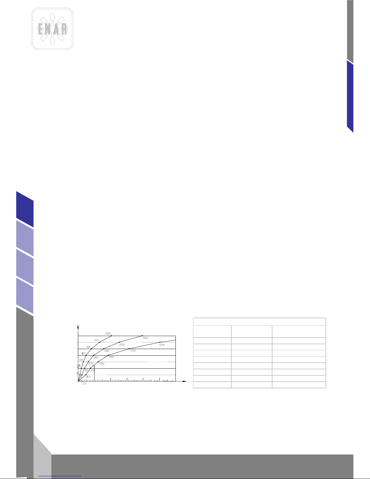
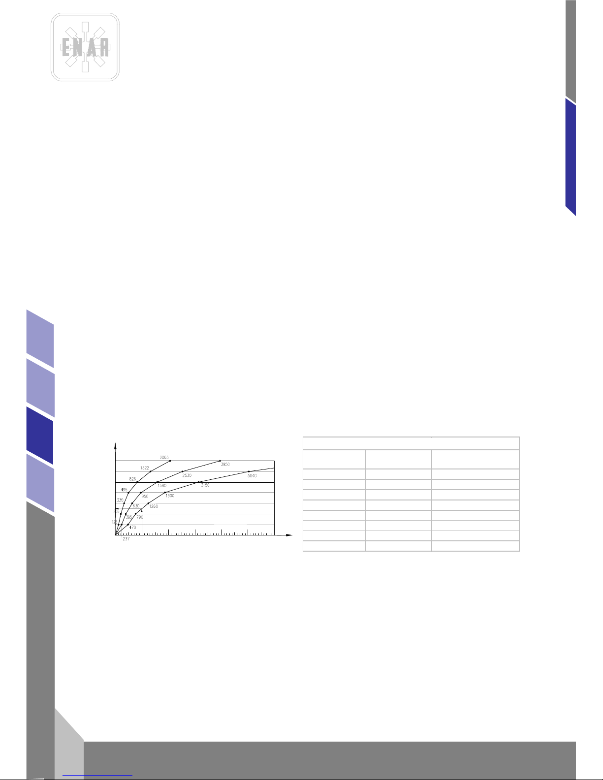
Para determinar la sección transversal seguir el siguiente procedimiento:
PROCEDIMIENTO PARA DETERMINAR LA SECCION TRANSVERSAL NECESARIA EN
PROLONGACIÓN DE CABLE:
1. La resistencia óhm i ca e inductiva del cable con una perdida de tensión permitida de un 5%, cos.phi
= 0,8 mediante la curva de frecuencia y tensión.
Por ej:
Tensión nominal: .................................... 1~ 220 V 50 Hz
Intensidad nominal:.. ..... ..... ..... .... ..... ..... ... 10 A
Longitud de cable:.................................... 100 m
Entrando en la curva con el producto: Intensidad x Longitud =10x100=1000 Am
Obtenemos una sección de 4 mm
2. El calentamiento permitido del cable según VDE ( tabla para la sección transversal mínima
requerida).
Por ej:
Para 10 A, según tabla para 15 A o inferior la sección es de 1 mm.
Por tanto, Sección escogida = 4 mm, siempre elegir la sección transversal mayor de
las dos comprobaciones.
Secció n (m m2)
Carga máx. (A) Fusible m áx . (A)
1 15 10
1,5 18 10/3-16/12,5 26 20
4 34 25
6 44 35
10 61 50
16 82 63
25 108 80
Seccione s mínim a s según norma s VDE
INTENSIDAD NOMINAL X LARGO DE LÍNEA (A m)
SECCIÓN DE LA LÍNEA EN mm
2
2,5
1,5
10
4
6
25
16
6000
3000
1000
0
2000
4000
5000
115 V
230 V
380 V
Page 12

CONVERTIDORES DE FRE CUE NCIA
11
es
AFG, AFD, AFE
4.4 MOTOR DE GASOLINA.
Leer el manual del fabricante del motor.
No trabajar en lugares con escasa ventilación.
Asegúrese que no hay ninguna materia combustible cerca del escape del motor.
Controlar que hay gasolina en el deposito de combustible.
Controlar que el nivel de ac eite al ca n za el nivel máximo en el motor (ver manual del
motor) y en elemento vibr ante (SAE 10 W 40).
1. GENERADOR ELECTRICO.
Inspeccionar el buen estado de los cables.
2. Cuando se comprueben defectos que pueden poner en peligro la manipulación, se debe
suspender el trabajo y realizar el mantenimiento correspondiente.
4.5 MANTENIMIEN T O PERIODICO
1. Los trabajos de las partes eléctricas solo deberán efectuarse por un experto.
2. Durante los trabajos de mantenimiento deberá asegurarse que está desconectado de la red.
3. En todas las operaciones de mantenimiento se utilizarán recambios originales.
4. No es necesaria una lubricación periódica de los rodamientos del convertidor.
5. El conductor eléctrico de tierra (verde-amarillo) deberá se r mas larg o par a que en el caso que
falle el freno de cable no sea el primero en cortarse. Después de trabajos de reparación o
mantenimiento, controlar el paso de corriente a través del cable de tierra.
6. Limpiar periódicamente las aberturas de ventilación en la parte frontal y trasera del convertidor
y del generador para prevenir sobrecalentamiento.
7. Después de trabajos de mantenimiento y servicio se deberá montar correctamente todos los
dispositivos de seguridad.
8. Aproximadam e nte a las 40 hor as de fu nc ion am i en to de ber án ins peccionarse los tornillos de
sujeción de la carcasa
9. Cada 12 meses o con más frecuencia dependiendo de las condiciones de uso, se recomienda
que sea revisado por un taller autorizado.
10. Durante los trabajos de mantenimiento deberá asegurarse que está desconectado el motor de
gasolina.
4.6 MANTENIMIENTO CON MOTOR DE GASOLINA
1. Diariame n te (8 hor as ).
Limpiar el motor, controlar tornillos y tuercas, chequear y rellenar de aceite el deposito del motor y el
del elemento vibrante.
2. Semanal (50 horas).
Cambiar el aceite del motor (inicial 20 horas), limpiar las bujías y el filtro de aire.
3. Mensual (200 horas).
Limpiar el filtro de aceite, limpiar y ajustar las bujías.
4. 500 horas.
Limpiar y ajustar el carburador, limpiar la cabeza del cilindro, reglaje de válvulas.
Page 13

CONVERTIDORES DE FRE CUE NCIA
es
12
AFG, AFD, AFE
5. En todas las operaciones de mantenimiento se utilizarán recambios originales.
6. Después de trabajos de mantenimiento y servicio se deberá montar correctamente todos los
dispositivos de seguridad.
7. Cada 12 meses o con más frecuencia dependiendo de las condiciones de uso se recomienda
que sea revisado por un taller autorizado.
8. No llenar el deposito de gasolina fumando, cerca de una llama u otro peligro potencial.
Cerrar la llave de paso antes de llenar el deposito, usar gasolina, limpiar las salpicaduras de
gasolina antes de arrancar el motor.
9. Ver libro de instrucciones del motor para ajuste de la velocidad, encendido y parada.
4.7 INSPECCION
1. Antes de iniciar los trabajos se deberá comprobar el correcto funcionamiento de todos los
dispositivos de manejo y seguridad.
2. Inspeccionar regularmente el buen estado de los cables de alimentación.
3. Inspeccionar siempre la tensión de conexió n.
4. Cuando se comprueben defectos que hagan peligrar la manipulación segura, se debe
suspender el trabajo y realizar el mantenimiento correspondiente.
5. El convertidor solo deberá ser utilizado en conjunto con todos los elementos de seguridad.
6. Si se comprueban defectos en los dispositivos de seguridad u otros defectos que disminuyan el
seguro manejo del equipo, se informará inmediatamente al responsable correspondiente.
4.8 ALMACENAMIENTO
Almacenar siem pr e el con ver tidor en zonas limpias, sec as y prot egi d as, c u an do no sea usado por
tiempo prolonga do.
4.9 TRANSPORTE
En vehículos de transporte se deberá asegurar el motor contra deslizamientos, vuelcos y gol pe s.
4.10 MANTENIMIENTO DE LA AGUJA VIBRANTE
Ver manual de mantenimiento de agujas vibrantes de alta frecuencia (AF_x_mu_01).
5 LOCALIZACIÓN DE AVERIAS
5.1 CONVERTIDORES ELÉCTRICOS
PROBLEMA CAUSA / SOLUCION
El convertidor no funciona ...................................................... Verifique si hay corriente.
Enchufe en mal estado
Interruptor defec t uos o
Convertidor estropeado
El motor funciona en forma normal..........................................Limpie las aberturas de entrada y
Pero se sobrecalienta salida de aira en la carcasa
Page 14
CONVERTIDORES DE FRE CUE NCIA
13
es
AFG, AFD, AFE
Las agujas vibrantes conectadas exceden
la capacidad del convertidor
El motor funciona lentamente y se...........................................Verifique la tensión de la fuerza eléctrica
sobrecalienta Puede que el motor este trabajando a dos
fases
Compuebe las especificaciones del cable
de prolongación
Compruebe la tensión en el conmutador de
tensión
El motor hace ruido excesivo....................................................R od am ient os def ectuoso
El inducido puede que roce con el estator
Carcasa rota o tornillos flojos
5.2 CONVERTIDORES GAS O LINA Y DIESEL
6 INSTRUCCIONES PARA SOLICITAR REPUESTOS
6.1 INSTRUCCIONES PARA PEDIR REPUESTOS
1.- En todos los pedi dos de repues tos DEBE INCLU IRSE EL CÓDIGO DE LA PIEZA SEGÚN LA
LISTA DE PIEZAS. Es recomendable incluir el NÚMERO DE FABRICACIÓN DE LA MÁQUINA.
2.- La placa d e i dentificación con los números de se rie y modelo se encuentran en el exterior d e la
carcasa del cubrecorreas en todos los medelos de fratasadora.
3.- Provéanos con las instrucciones de transporte correctas, incluyendo la ruta preferida, la
dirección y nombre completo del consignatario.
4.- No devuelva repuestos a fábrica a m en os que tenga p erm iso por escrit o de la m is m a, to das l as
devoluciones autorizadas deben enviarse a portes pagados.
6.2 INSTRUCCIONES PARA SOLICITAR GARANTÍAS
1.- La garantía tiene validez por 1 año a partir de la compra de la máqui na. L a garantía c ubri rá l as
piezas con defecto de fabricación.
- En ningún caso la garantía cubrirá una avería por mal uso del equipo.
2.- En todas las solicitudes de garantía DEBE ENVIARSE LA MÁQUINA A ENARCO, S.A. O
TALLER AUTORIZADO, indicando siempre la dirección y nombre completo del consignatario.
PROBLEMA CAUSA/SOLUCION
El motor no funciona
1.- Verifique si ha gasoli na en el depósito.
2.- Compruebe la llave de paso de gasolina.
3.- Compruebe la palanca de aire .
El generador eléctrico se
calienta
1.- Limpiar las aberturas de entrada y salida de aire.
2.- Las agujas vibrantes conectadas exceden la capacidad del generador
Page 15

CONVERTIDORES DE FRE CUE NCIA
es
14
AFG, AFD, AFE
3.- El departame nto de S .A.T . notific ará d e inmedi ato si s e ace pta la g arant ía y en el cas o de qu e
se solicite se enviará un informe técnico.
4.- No tendrá ningún ti po de garant ía cual quier equi po que h aya sid o previ ament e manipul ado po r
personal no vinculado a ENARCO, S.A.
NOTA: ENARCO, S.A. se reserva el derecho a modificar cualquier dato de este manual sin previo aviso
Page 16

FRECUENCY CONVERTERS
1
en
AFG, AFD, AFE
INDEX
1 INTRODUCTION 2
2 SPECIFICATIONS OF THE CONVERTERS 3
2.1 FRECUENCY CONVERTERS 3
2.2 FREQUENCY CONVERTER WITH PETROL ENGINE 6
3 USAGE CONDITIONS 6
WARNING! READ AND UNDERSTAND ALL INSTRUCTION 6
4 OPERATION AND MAINTENANCE 8
4.1 GETTING STARTED 8
4.2 VIBRATING POKER CONNECTION TO THE CONVERTERS 8
4.3 CONVERTER CONNECTION TO THE SYSTEM 9
4.4 PETROL ENGINE 10
4.5 INSPECTION 10
4.6 PERIODIC MAINTENANCE 10
4.7 MAINTENANCE WITH PETROL ENGINE 10
4.8 STORAGE 11
4.9 TRANSPORTATION 11
4.10 MAINTENANCE OF THE VIBRATING POKERS 11
5 LOCATING MALFUNCTIONS 11
5.1 ELECTRIC CONVERTERS 11
5.2 PETROL CONVERTERS 12
6 INSTRUCTIONS TO ORDER SPARE PARTS 12
6.1 INSTRUCTIONS TO ORDER SPARE PARTS 12
6.2 NSTRUCTIONS TO REQUEST WARRANTIES 12
Page 17

FRECUENCY CONVERTERS
en
2
AFG, AFD, AFE
1 INTRODUCTION
Thank you for trusting the ENAR brand
For the maximum performance of the equipment, we recomm end to re ad c ar ef ully the safety
recommendations, maintenance, and usage listed in this manual
Defective parts should be replaced immediately to avoid major problems.
The effective longevity of the equipment will increase if the manual instructions are followed.
We will glad to help you with an y com m ents or sugg es tio ns in refe re nc e to ou r equi pm ent.
Page 18

FRECUENCY CONVERTERS
3
en
AFG, AFD, AFE
2 SPECIFICATIONS OF THE CONVERTERS
TYPE:
Mechanic converter
It is composed of a motor and a generator with magnetic induced circuit (without brushes)
FUNCTION:
Transform the intake voltage and frequency into a issue voltage of 42 V -200 Hz (triple phase) to
supply the vibrating pokers with internal motor ref. ENAR M38AF, M5AF, M6A F, M7AF and M8AF
EXTENSION CABLES:
5m length, standard machine with connexion plugs type CE, insulation 750V
CONNECTION POSSIBILITIES:
The consumption in charge of the connecte pokers do not increase the issue voltage specified in the
electronic characteristics table.
2.1 FRECUENCY CONVERTERS
MODEL PLASTIC SUITCASE:
Three phase: AFE 2000 P, AFE 1000 P
Single phase: AFE 2000M P, 1000M P
P, HEAVY DUTY PLASTIC, with a protection against dust and splash
MODEL TUBULAR FRAME:
Three phase: AFE 2000 T, AFE 2500
Single phase: AFE 2000MT, AFE2000MT 230V
T, TUBULAR FRAME
MODEL HIGH RESISTANCE TUBULAR STEEL FRAME WITH CARRIEGE
Three phase: AFE3500, AFE4500, AFE6000
HOUSING:
HIGH RESISTANCE STEEL FRAME, with WHEELS
Page 19
FRECUENCY CONVERTERS
en
4
AFG, AFD, AFE
* at 1 m of distance of the converter, K =2
Models Weight Kg
Nb of
Outpouts
Possibilities of connections of vibrating pokers
ENAR
M38A
M5AF
M6AF
M7AF/M8AF
AFE 2000 P
25
2
2
2
1
1
AFE 1000 P
15
1
1
1
1
-
AFE 2000MP
27
2
2
2
1
1
AFE 1000MP
17
1
1
1
-
-
AFE 2500 T
34 3 5 3 2
2
AFE 3500
70 4 8 4 3
2
AFE 4500
74 4 9 5 4
4
AFE 6000
83
4
10
6
5
4
AFE 1000MT
20
1
1
1
-
-
AFE 2000T
28
2
2
2
1
1
AFE 2000MT
30
2
2
2
1
1
AFE 2000MT 230V
30
2
This converter uses 230V Pokers
KW AMP
V KW
AMP
V
AFE2000 P
2,8KW 4,0A 400V 3-/50Hz 1,6KVA 23 A
42V 3-/200Hz
64
AFE1000 P
1,7KW 2,5A 400V 3-/50Hz
1,0KVA 13 A
42V 3-/200Hz
62
AFE2000M P
2,0KW 9A
230V 1-/50Hz 1,6KVA
23 A 42V 3-/200Hz
66.5
AFE2000M P 60 Hz
2,0KW
9A 230V 1-/60Hz 1,6KVA
23 A 42V 3-/240Hz
66,5
AFE2000MT 230V
2,0KW 9A 230V 1-/50Hz 1,6KVA
23 A 230V 3-/200Hz
64
AFE1000M P
1,3KW 6A 230V 1-/50Hz 1,0KVA 13 A
42V 3-/200Hz
62
AFE2000T
2,8KW
4,0A 400V 3-/50Hz 1,6KVA 23 A 42V 3-/200Hz
64
AFE2000MT
2,0KW 9A
230V 1-/50Hz 1,6KVA 23 A 42V 3-/200Hz
64
AFE1000MT
1,3KW
6A 230V 1-/50Hz 1,0KVA
13 A 42V 3-/200Hz
62
AFE2500T
4KW 6A 400V 3-/50Hz 2,5KVA 35 A 42V 3-/200Hz
66
AFE3500
6KW 8A 400V 3-/50Hz 3,5KVA
50 A 42V 3-/200Hz
68,5
AFE4500
7KW 10A 400V 3-/50Hz 4,5KVA 61 A 42V 3-/200Hz
70
AFE6000
8KW 12A 400V 3-/50Hz
6KVA 82 A 42V 3-/200Hz
70
Sound
press. Level
L
PA *
ELECTRICAL CHARACTERISTICS
INPUT
OUTPUT
MODEL
Page 20
FRECUENCY CONVERTERS
5
en
AFG, AFD, AFE
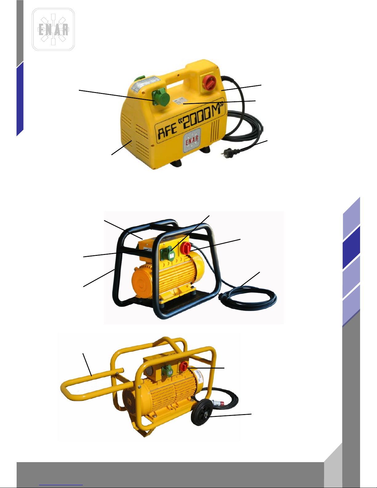
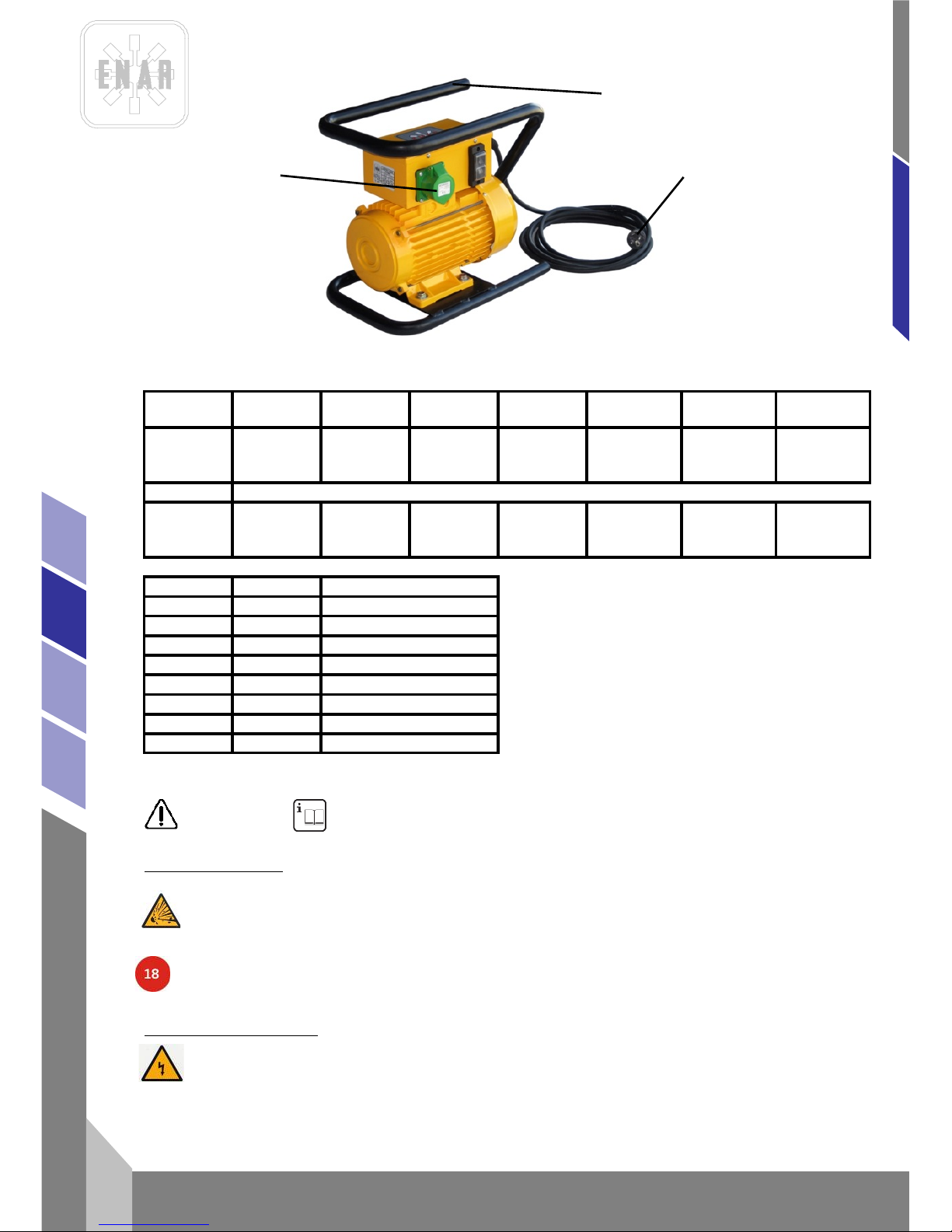
AFE 2000P, AFE 2000MP, AFE 1000P, AFE 1000MP PLASTIC HOUSING
DATA PLATE
SWITCH (START-STOP)
PLUG 2F+E or 3F+E
AND CABLE 5 m
AFE 2000T, AFE 2500T, AFE 2000MT, AFE 1000MT TUBULAR FRAME
SWITCH (START-STOP)
SWITCH (START-STOP)
SOCKET TO CONNECT
VIBRATORS 200 Hz < 50 V
PLASTIC HOUSING
PLUG 2F+E or 3F+E
AND CABLE 5 m
TUBULAR FRAME
CONNECTION BOX
AFE 3500, AFE 4500 AND AFE6000 CARRIEGE WHEEL FRAME
DATA PLATE
SOCKET TO CONNECT
VIBRATORS 200 Hz < 50 V
HANDLE
WHEELS
Page 21
FRECUENCY CONVERTERS
en
6
AFG, AFD, AFE
2.2 FREQUE NCY CONVE RT ER WITH PETROL ENGINE
3 USAGE CONDITIONS
WARNING! Read and underst and al l instruction
3.1 WORKING AREA
KEEP your working area clean and well lit. Cluttered benches and dark areas invite accidents.
DO NOT OPERAT E power tools i n explosive atmosph eres, such as i n the presence of flammable
liquids, gases, or dust.
KEEP AWAY from standers, children, and visitors while operating a power tool. Distractions can cause
to loose control.
Machine must be operated by reliable operato rs who r ead and unde rs tand the ope rati on ma nua l
of age above 18.
3.2 ELECTRICAL SAFETY
GROUNDED TOOLS MUST BE PLUGGED INTO an outlet properly installed and grounded in
accordance wit h all cod es an d ordi n an c es.
NEVER REMOVE the grounding prong or modify the plug in any away.
DO NOT USE any plug adaptor.
MODEL WEIGHT OUTPUTS ENGINE GENRATOR POKERS
Sound press.
Level LPA *
Sound power
Level LPA *
AFGH2000
38Kg 2 5.5HP HONDA 42V / 200HZ
2M5AF / 1M6AF
/ 1M7AF/
1M8AF
85
96
AFDY2000 48Kg 2
4,7 HP
YANMAR
42V / 200HZ
2M5AF / 1M6AF
/ 1M7AF/
1M8AF
87 99
MODEL
GX 160K1
STROKES
4, 163cc
POWER 5.5HP/3600rpm
TORQUE
m
RPM 3900rpm
IGNITION
TRANSISTOR
COMBUST GASOLINA
WEIGHT 15Kg
OIL 0.61
0.81
26Kg
DIESEL
INJECTION
3600rpm
1.25Kgm/2800rpm
4.7HP/3600rpm
4, 211cc
YANMAR L48
DIESEL
SOCKET
FRAME
PLUG 2F+E or 3F+E
AND CABLE 5 m
Page 22
FRECUENCY CONVERTERS
7
en
AFG, AFD, AFE
CHECK with a qualified electrician if you are in doubt as to whether the outlet is properly grounded.
AVOID body contact with grounded surfaces such as pipes, radiators, ranges and refrigerators.
DO NOT EXPOSE power tools to rain or wet conditions.
DO NOT ABUSE the cord.
NEVER USE the cord to carry the tools or the plug from an outlet.
KEEP cord away from heat, oil, sharp edges or moving parts.
REPLACE damaged cords immediately. Damaged cords increase the risk of electric shock.
WHEN OPERATING a power tool o utside, use an outdoor e xtension cord marked “W -A”, “W” or
"H07RN-F".
3.3 PERSONAL SAFETY
STAY ALERT, watch what yo u ar e doin g and use c om m on sen se w he n ope rating a power tool.
DO NOT USE TOOL while tired or under the influence of drugs, alcohol, or medication.
DRESS PROPERLY.
DO NOT WEAR loose clothing or jewellery.
CONTAIN long hair. KEEP your hair, clothing, and gloves away from moving parts.
AVOID accidental starting.
BE SURE switch is off before plugging in.
REMOVE adjusting keys or switches before turning the tool on.
DO NOT overreach.
KEEP proper footing and balance at all times.
USE safety equipment.
Always WEAR eye protection.
3.4 TOOL USE AND CARE
USE clamps or other practical way to secure and support the work piece to a stable platform.
DO NOT FORCE tool.
USE the correct tool for your application.
DO NOT USE tool if switch does not turn it on or off.
DISCONNECT the plug from the power source before making any adjustments, changing
accessories, or storing the tool.
STORE idle tools out of reach of children and other untrained persons.
MAINTAIN tool with care.
CHECK for misalignment or binding of moving parts, breakage of parts, and any other condition that
may affect the tools operation. If damaged, have the tool serviced be for e usi n g.
USE only accessories that are recommended by the manufacturer for your model.
3.5 SERVICE
Tool service MUST BE PERFORMED only by qualified repair personnel.
When servicing a tool, USE only identical replacement parts.
FOLLOW instructions in the Maintenance section of this manual.
3.6 ESPECIFIC SAFETY RULES
For the proper operation of the converter, MAKE SURE that operators have been instructed in the
proper management of this machine.
The converter SHOULD ONLY BE USED in the specific jobs for with it the help of this manual.
Before connecting the converter to the electrical system, MAKE SURE that the voltage and
frequency coincide with the ones stated in the characteristics equipment plate, located in the top part
of the plastic housing.
ENSURE that all frame screws are tight before starting work.
The motor plug should not be used to start or stop the equipment.
The electrical feeding cable should not be used to remove the plug from the socket.
Protect the electrical feeding cable against heat, oil or sharp edges.
DO NOT WORK CLOSE to flammable liquids or in areas exposed to flammable gases.
Page 23
FRECUENCY CONVERTERS
en
8
AFG, AFD, AFE
TO AVOID the flattening of the cable by heavy machinery with could cause breakage.
Do not permit untrained personnel to operate the motor or connexion.
Maintain free venti lation of air.
Keep the converter clean and dry.
Before doing any work of maintenance, disconnect the motor from the electrical system.
When connecting to a generator, make sure that the out tension and frequency is stable, right and
has the proper power.
(the converter feeding voltage should not vary than +/- 5% as stated on the converter plate.
The level of acoustic pressure is less than 70 dB. Prop er pr otective equipme nt sho ul d be use d w hen
the noise level gets to be more than 70 dB.
Respect the maximum number of vibrating pokers that can be connected to the converter.
Avoid having the converter working unloaded during long periods of time. The vibrating pokers
should not be working out of concrete. Switch on the poker before starting working an disconnecting
them immediately after finishing the vibrating operation.
When finishing the job or when taking a break, the operator should switch off, disconnect it from the
electrical system, place it in such a way that should not fall or tip
This screed can be used only under the applications for which it has been designed and according to
these safety instructions.
When working with a petrol engine:
- Read the motor manufacturer's manual before working.
- Do not work in closed rooms, the exhaust fumes may be toxic.
-·Wait 2 minutes for the petrol refill until the motor get colder.
The acoustic power level of this mac hine can reac h 95 dB. P roper protectiv e equipme nt should be
used.
IN ADDITION, LOCAL COUNTRY STABLISHED ORDINANCES SHOULD BE RESPECTED.
4 OPERATION AND MAINTENANCE
4.1 GETTING START ED
1.- Before startin g t he job, ch ec k the co rrec t working of all handling an d safety devices
2.- Inspect regularly the good conditions of the feeding cables. If is necessary change the cord,
check section Extension cables.
3.- Inspect regularly the connection voltage.
4.- The converter should only be used in conjunction with all safety elements.
5.- Check the screws
6.- If defects are found in the safety devices or other defects which could reduce the safe handling of
the equipment, notify immediatel y the prope r responsible perso n.
4.2 VIBRATING POKER CONNECTION TO THE CONVERTERS
The converter has a socket to connect the vibrating pokers.
Connection possibil ities:
The input current of the pokers connected in load shall not exceed the out current specified in the
electrical characteristic table.
Page 24
FRECUENCY CONVERTERS
9
en
AFG, AFD, AFE
4.3 CONVERTER CONNECTI O N TO THE SYSTEM
Check the converter switch is off before connecting to the system.
Unless otherwise stated at the time of ordering, the frequency converters three pha se will be
connected at the factory as three phase, 400V 50 Hz. The models single phase, will go out of the
factory to be used as 230V 50 Hz single phase charge.
Disconne ct in g the eq ui pm ent:
First, stop the vibrating pokers by turning off the proper switch, second stop the converter by turning
off the proper switch, and finally remove the feeding cable from the system.
Earth conne c ti on .
To protect the user from an electrical shock, the converter should be correctly connected to earth.
The converters are equipped with three cables (single phase) or four cables (three phase) and their
respective plugs. The adequate earth socket should be used to connect the converters. If the socket
with earth is not available, an earth adapter should be used before connecting the plugs.
Extension cables.
Always use extension cables with earth wire and its respective plug with earth in the female and
male plug.
Do not use damaged or worn out cables.
Avoid heavy loads on cables.
To determine the transversal section, follow the following procedure:
PROCEDURE TO DETERMINE THE NECESSARY TRANSVERSAL SECTION IN CABLE
EXTENSION
Do the following verifications and take the highest section of cabl e:
1. The ohmic resistance and inductive resistance of the cable with the permitted loss of voltage of 5%,
cosphi=0.8 trough the frequency and voltage curve
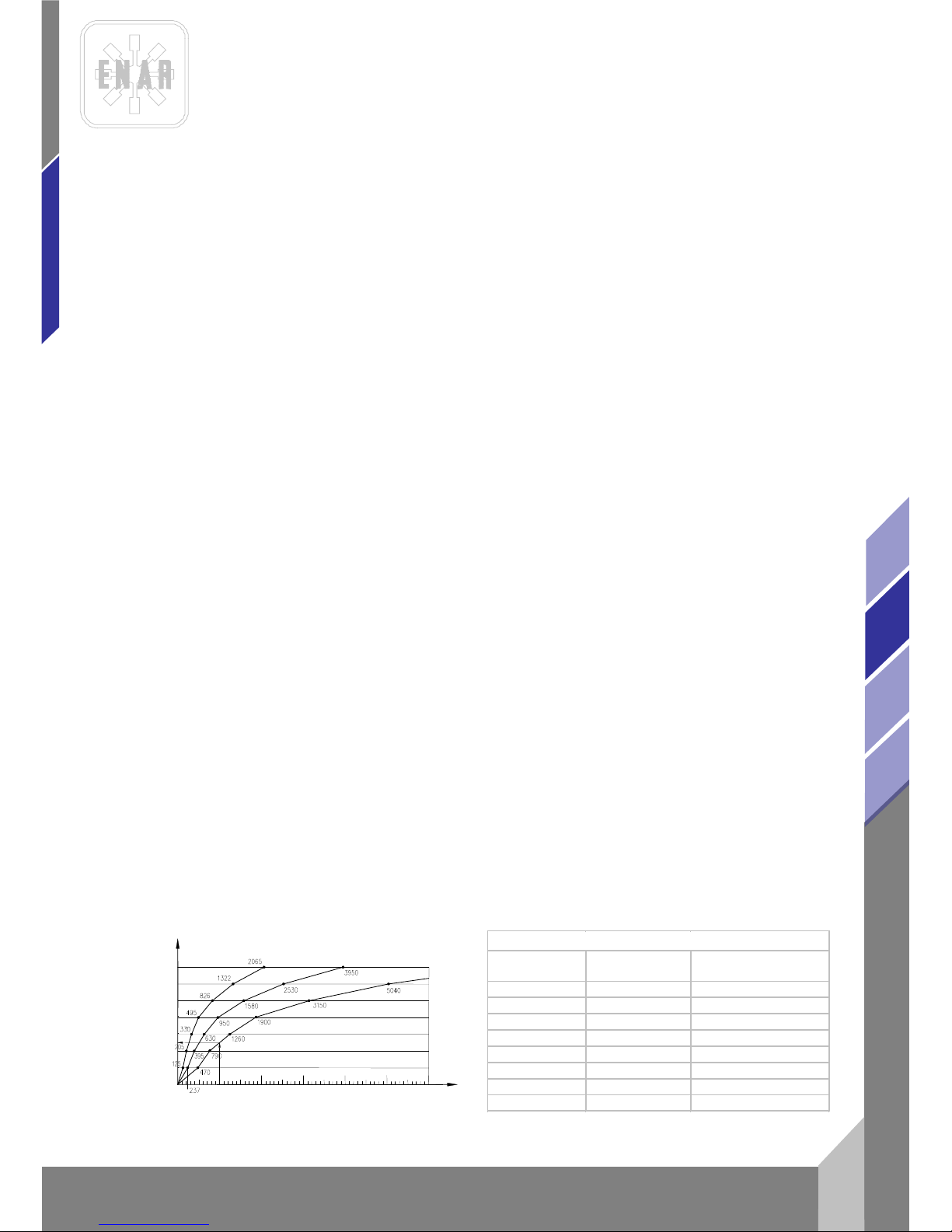
I.e: Voltage nominal:......... ..... ............. 1- 220 V 50 Hz
Nominal current:............................ 10 A
Cable length:................................. 100 m
Entering the curve with the product: Intensity x Length=10x100=1000 Am We obtain a 4 mm2 section
2. The permitted heating of the cable according to VDE standard ( minimum transversal section table
required).
I.e: For 10 A, according to table for 15 A or less, the section is of 1 mm2.
Therefore, the section chosen is equal to 4 mm
2
, Always choose the highest transversal section of
the two verifications
INTENSIDAD NOMINAL X LARGO DE LÍNEA (A m)
SECCIÓN DE LA LÍNEA EN mm
2
2,5
1,5
10
4
6
25
16
6000
3000
1000
0
2000
4000
5000
115 V
230 V
380 V
Secció n (m m
2
)
Carga máx. (A) Fusible m áx . (A)
1 15 10
1,5 18 10/3-16/12,5 26 20
4 34 25
6 44 35
10 61 50
16 82 63
25 108 80
Seccione s mínim a s según norma s VDE
Page 25

FRECUENCY CONVERTERS
en
10
AFG, AFD, AFE
4.4 PETROL ENGINE
Read the motor manufacturers’ manual.
Do not work in rooms with scarce ventilation.
Make sure there is no flammable good near to the escape.
Check the petrol level in the reservoir.
Check the oil reservoir of the motor is full (see motors’ manual) and the oil reservoir in the
vibrating group that also contains the exciter (10W 40 non faoming).
1- ELECTRIC GENERATOR
Make sure the cables are in good condition.
2- When a defect or a malfunction has be en det ected, endangerin g the use of t hi s mac hin e or
not, stop the work and make the correspondent maintenance to avoid any danger or bigger
damage.
4.5 INSPECTION
Before starting the job, check the correct working of all handling and safety devices
Inspect regularly the good conditions of the feeding cables.
Inspect regularly the connection voltage.
The converter should only be used in conjunction with all safety elements.
If defects are found in the safety devices or other defects which could reduce the safe handling of
the equipment, notify immediatel y the prope r responsible perso n.
4.6 PERIODIC MAINTENANCE
-Only an expert shall work on the electrical parts.
-Make sure that the current is off during repairs.
-In all maintenance operations, origi nal par t s will be us e d.
-A periodic lubrication of the converter bearings is not necessary.
-The electrical earth wire (green-yellow) should be longer to avoid being the first one in cutting in
case of breaking of wires. After maintenance, control the current through the earth cable .
-Clean the ventilation vents in the front and back part of the converter periodically to avoid
overheating.
-After maintenance job and service, all safety devices should be assembled correctly.
-After working 40 hours inspect the frame holding bolts.
-Every 12 months or more frequently, depending on the usage conditions, it is recommended an
inspection be done by an authorized dealer.
-During the maintenance, secure that the device is disconnected from the power source.
4.7 MAINTENANCE WITH PETROL ENGINE
1. Daily (8 hours).
Clean the motor and the beams, check the bolts & nuts, check and fill the exciters’
and motors’ reservoir with the respective oils.
2. Weekly (50 hours).
Change the motor oil (first 20 hours), clean the sparking plugs and the air filter.
3. Monthly (200 hours).
Page 26

FRECUENCY CONVERTERS
11
en
AFG, AFD, AFE
Clean the oil filter, clean and adjust the sparks plugs.
4. Every 500 hours.
Clean and set the carburettor, clean the cylinders’ head, set the valves.
5. Always use ori ginal parts by every mainte nan ce op eration.
6. The safety fittings have to be checked after every maintenance.
7. The screed has to be sent to an auth ori z ed work s ho p for ser vi ce eve r y 12 mo n ths
or more frequently according to the intensity of the usage.
8. Do not fill the petrol reservoir while smoking or near any other potential source of
danger.
Lock the petrol admission key when filling, use unleaded gas, clean the gas spelt.
9. See the motors’ manual to set the motors’ speed, starting and stopping.
4.8 STORAGE
When the conver ter has not been used for lo ng peri ods of tim e, it shoul d always be stored i n clean,
dry, and protected ar eas .
4.9 TRANSPORTATION
When transporting by vehicles, ensure the converter is safe against slipping, overturning and blows.
4.10 MAINTENANCE OF THE VIBRATING POKERS
See instruction manual of the high frequency vibrating pokers (AF_x_mu_01).
5 LOCATING MALFUNCTIONS
5.1 ELECTRIC CONVERTERS
ROBLEM CAUSE/SOLUTION
The converter is not working....................................................See if it has power
Plug in need of repair
Defective switch
Converter is broken down (motor or
generator)
The motor works but it o verhe at s. ... .. . ......................................Clean the in and out of frame air vents
The connecting vibrating pokers exceed
the converters capacity.
The motor works slowly and it overheats................................Verify the voltage of the electrical system
The converter might be working at two
phases
Check the cable specifications
Check the voltage in the voltage switch (if
apply)
Page 27
FRECUENCY CONVERTERS
en
12
AFG, AFD, AFE
The converter makes excessive noise......................................Defective bearings
The rotor might touching the stator
The frame is broken or has loose
5.2 PETROL CONVERTERS
6 INSTRUCTIONS TO ORDER SPARE PARTS
6.1 INSTRUCTIONS TO ORDER SPARE PARTS
1. All spare parts request must include PART CODE NUMBER AS STATED IN THE PART
LIST.We recommend to inclu de ITE M´ S MANU FA CT UR E NU MBER.
2. The identifica tion plate with manuf acture and model numb er is located in the top part of t he
motors’ plastic frame. The transmission and pokers have the manufacture number engraved outside.
3. Let us to know the correct shipping instructions, including the wished route and the address and
consignee's com pl ete nam e.
4. Do not return the parts without authorization, the return are done freight prepaid.
6.2 NSTRUCTIONS TO REQ UEST WARRANTIES
The warranty is val id 1 year aft er the purch asing of the m achine, The warrant y will cover pa rts with
manufactures’ defects. In no cas e th e w arr an t y will cov er a m al f unction due to impro per us a ge o f the
equipment. Labour and shipping fees will always be paid by the customer.
2. In all warranty requests THE MACHINE MUST BE SENT TO ENARCO, S.A. or to an
AUTHORIZED SHOP, always including the complete address and name of the consignee.
3. The Technic al Assistanc e Service will immediatel y notify you i f it accepts th e warrant y and if
requested, it will se nd a tech ni cal re port.
4. The warranty will be void if any equipment has been previously handled by personnel outside of
ENARCO, S.A. or not authorized by it.
NB:
ENARCO, S.A., reserves the right to modify any part of this manual without prior notice.
PROBLEM
CAUSES/SOLUTIONS
The motor doesn´t work
1.- Check the gas level.
2.- Check the gas admission key is open.
3.- Check the choke postition .
The electric g enerator is
overheating
1.- Clean the air ventilation (inlet and outlet).
2.- The connecting vibrating pokers exceed the converters
Page 28

CONVERTISSEURS DE FRE Q UE NCE
1
fr
AFG, AFD, AFE
INDICE
1 PROLOGUE 2
2 CARACTERISTIQUES DU MOTEUR ELECTRIQUE 3
2.1 CARACTERISTIQUES DU CONVERTISSEURS DE FREQUE NCE 3
2.2 CARACTERÍSTIQUES DU MOTEUR A ESSENCE 4
3 CONDITIONS D’UTILISATION 6
3.1 AIRE DE TRAVAIL 6
3.2 SÉCURITÉ ÉLECTRIQUE 7
3.3 SÉCURITÉ DES PERSONNES 7
3.4 UTILISATION ET ENTRETIEN DES OUTILS 7
3.5 RÉPARATION 8
3.6 RÈGLES DE SÉCURITÉ PARTICULIERES 8
4 MANIPULATION ET ENTRETIEN 9
4.1 MISE EN SERVICE 9
4.2 CONNEXION DES AIGUILLES AU CONVERTISSEUR 9
4.3 CONNEXION DU CONVERTISSEUR AU RESEAU 9
4.4 MOTEUR ESSENCE
10
4.5 ENTRETIEN PERIODIQUE
11
4.6 ENTRETIEN AVEC UN MOTEUR ESSENCE 11
4.7 INSPECTION 11
4.8 ENTREPOSAGE 12
4.9 TRANSPORT 12
4.10 ENTRETIEN DE L'AIGUILLE VIBRANTE 12
5 LOCALISATION DES PANNES 12
5.1 CONVERTISSEURS ELECTRIQUE 12
5.2 CONVERTISSEURS ESSENCE 13
5.3 CONVERTISSEURS ELECTRONIQUES 13
6 L’APPROVISIONNEMENT EN PIECES DETACHEES 14
6.1 INSTRUCTIONS POUR COMMANDER LES PIECES DETACHEES 14
6.2 INSTRUCTIONS POUR FAIRE JOUER LA GARANTIE 14
Page 29

CONVERTISSEURS DE FREQUENCE
fr
2
AFG, AFD, AFE
1 PROLOGUE
Nous vous remercions de la confiance que vous avez déposé en la marque ENAR.
Pour profiter de vot re ap par eil ENAR , nous vous recommandons de bien vouloir lire attentivement
les recommandations de sécurité, entretien et utilisation que regroupe ce manuel d'instructions.
Les pièces défectu eu ses doiv ent être remplacées po ur év it er des problèmes majeurs.
Le degré d'efficacité de l'appareil se verra amélioré si les instructions sont suivies comme indiqué ci-
après.
Nous tenons à votre enti èr e disposition pour répondre à tout type de remarque, question ou
suggestion concernant cet appareil ENAR
Page 30

CONVERTISSEURS DE FRE Q UE NCE
3
fr
AFG, AFD, AFE
2 CARACTERISTIQUES DU MOTEUR ELECTRIQUE
TYPE:
Avec convertisseur mécanique
Composé d'un moteur et d'un générateur avec un induit magnétique (sans balai)
Avec convertisseur électronique:
Composé d'un convertisseur de fréquence électronique et transformateur. L'ensemble avec
ventilation forcée.
APPLICATION:
Transformer la te nsio n et fréq ue nce d'e nt r ée en un e tension de sortie de 42 V triphasé et 200Hz
pour brancher les aiguilles vibrantes à moteur interne Ref. ENAR M35A F, M5 A F, M6A F et M7A F.
CABLE DE CONNEXION:
5 m de long, matériel standard avec une fiche de connexion type CE, isolation 1 KV
POSSIBILITES DE CONNEXION:
La consommation des aiguilles connectées en charge ne devra pas dépasser l'intensi té de sorit e
spécifique dans la table de caractérisatiques.
2.1 CARACTERISTI Q UES DU CONVERTISSEURS DE FREQUENCE
MODELE:
TRIPHASE: AFE 2000 P, AFE 1000 P
MONOPHASE: AFE 2000M P, AFE 1000M P
CARCASSE:
Plastique de haute résistance avec une protection contre la poussière et les éclaboussures.
MODELE:
TRIPHASE : AFE 2000 T , AFE 2500
MONOPHASE : AFE 2000 MT , AFE 2000MT 230v
CARCASSE :
Acier tubulaire.
MODELE :
TRIPHASE: AFE 3500, AFE 4500, AFE 6000
CARCASSE :
ACIER TUBULAIRE AVEC CHARIOT DE TRANSPORT ET ROUES EN ACIER CABLE DE
CONNEXION AU RESEAU
Page 31
CONVERTISSEURS DE FREQUENCE
fr
4
AFG, AFD, AFE
2.2
2.3
2.4
2.5
2.6
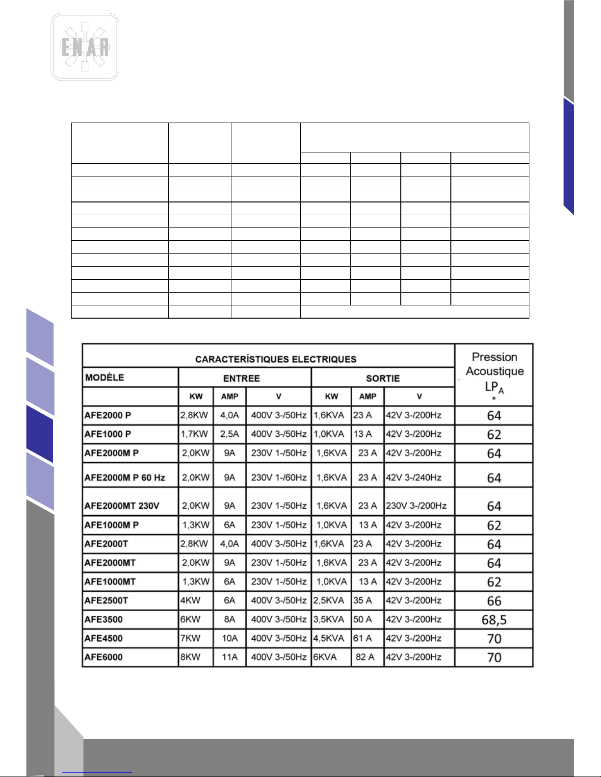
* un 1 m du convertisseur, K =2
Modèles Poids Kg
Nº de
sorties
Posibilités de connections des aguilles
vibrantes ENAR
M38A
M5AF
M6AF
M7AF/M8AF
AFE 2000P
25
2
2
2
1
1
AFE 1000P
15
1
1
1
1
-
AFE 2000MP
27
2
2
2
1
1
AFE 1000MP
17
1
1
1
-
-
AFE 2500T
34 3 5 3 2
2
AFE 3500
70 4 8 4 3
2
AFE 4500
74 4 9 5 4
4
AFE 6000
83
4
10
6
5
4
AFE 1000MT
20
1
1
1
-
-
AFE 2000T
28
2
2
2
1
1
AFE 2000MT
30
2
2
2
1
1
AFE 2000MT 230V
30
2
Ce convertisseur utiliser aguilles de 230 V
Page 32
CONVERTISSEURS DE FRE Q UE NCE
5
fr
AFG, AFD, AFE
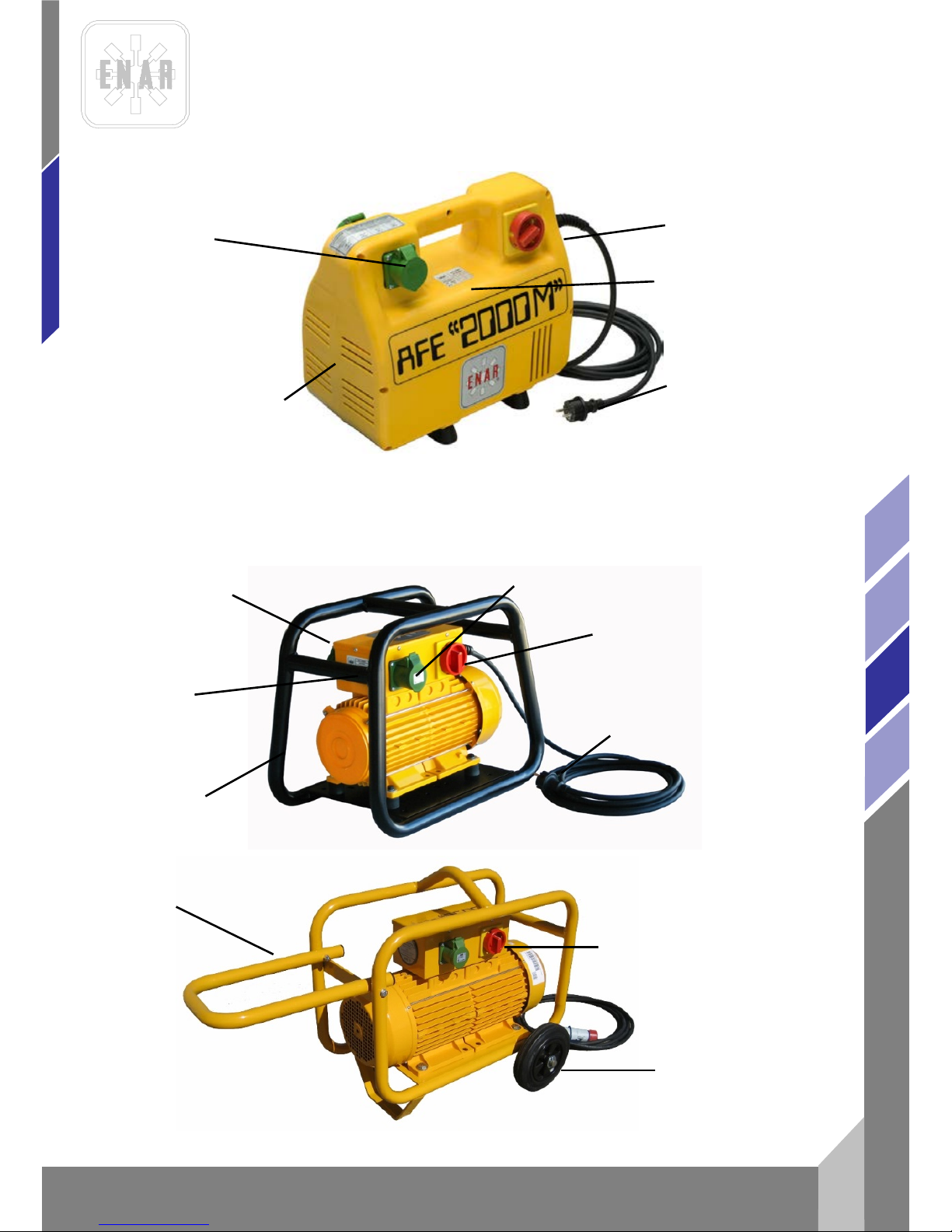
PRICE POUR CONNECTER LE
VIBRATEUR 200 Hz < 50 V
PLAQUE SIGNALÉTIQUE
INTERRUPTEIR (STARTSTOP)
CARCASSE
PLASTIQUE
AFE 2000P, AFE 2000MP, AFE 1000P, AFE 1000MP PLASTIC HOUSING
PRICE 2F+E O 3F+E
ET CÂBLE 5 m
PRICE POUR CONNECTER LE
VIBRATEUR 200 Hz < 50 V
INTERRUPTEIR (STARTSTOP)
PRICE 2F+E O 3F+E ET
CÂBLE 5 m
PLAQUE
SIGNALÉTIQUE
BOÏTER DE
CONNEXION
AFE 2000T, AFE 2500T, AFE 2000MT, AFE 1000MT TUBULAR FRAME
AFE 3500, AFE 4500 AND AFE6000 CARRIEGE WHEEL FRAME
INTERRUPTEIR (STARTSTOP)
MANIPULER
ROUES
ACIER
TUBULAIRE
Page 33
CONVERTISSEURS DE FREQUENCE
fr
6
AFG, AFD, AFE
2.2 CARACTERÍSTIQUES DU MOTEUR A ESSENC E
MODÈLE POIDS SORTIES MOTEUR GENERATEUR AIGUILLES
AFGH2000 38Kg 2 5.5HP HONDA 42V / 200HZ
2M5AF / 1M6AF / 1M7AF/
1M8AF
DIESEL
AFDY2000 48Kg 2 4,7 HP YANMAR 42V / 200HZ
2M5AF / 1M6AF / 1M7AF/
1M8AF
MODÈLE GX 160K1 YANMAR
TEMPS 4, 163c c 4, 211cc
PUISSANSE 5.5HP/3600rpm 4.7HP/3600rpm
PAIR 1.1Kgm/2500rpm 1.25Kgm/2800rpm
RPM 3900rpm 3600rpm
ALLUMAGE TRANSISTOR INJECTION
COMBUST GASOLINA DIESEL
RESERVOIR 3.61 2.51
POIDS 15Kg 26Kg
HUILE 0.61 0.81
3 CONDITIONS D’UTILISATION
AVERTISSEMENT! VOUS DEVEZ LIRE ET COMPRENDRE TOUTES LES
INSTRUCTIONS
3.1 AIRE DE T R AVAIL
3.2
VEILLEZ à ce que l'aire de tra vai l soi t p rop re et bien éclairée
N'UTILISEZ pas d'outils électriques dans une atmosphère explosive, par exemple en présence de
liquides, de gaz ou de poussières inflammables.
INTERRUPTEIR
BOÏTER DE
CONNEXION
CHÂSSIS
PRICE 2F+E O 3F+E
ET CÂBLE 5 m
Page 34
CONVERTISSEURS DE FRE Q UE NCE
7
fr
AFG, AFD, AFE
TENEZ à distance les curieux, les enfants et les visiteurs pendant que vous travaillez avec un outil
électrique.
3.3 SÉCURITÉ ÉLECTRIQUE
LES OUTILS MIS À LA TERRE doivent être branchés dans une prise de courant correctement
installée et mise à la terre conformément à tous les codes et règlements pertinents
NE MODIFIEZ jamais la fiche de quelque façon que ce soit, par exemple en enlevant la broche de
mise à la terre.
N'UTILISEZ pas d'adapteur de fiche
ADDRESEZ VOUS à un électricien qualifié, si vous n'êtes pas certain que la prise de courant est
correctement mise à la terre.
EVITEZ tout contact corporel avec des surfaces mises à la terre (tuyauterie, radiateurs, cuisinières,
réfrigérateurs,..)
N'EXPOSEZ pas les outils électriques à la pluie ou à l'eau
NE MALTRAITEZ pa s le cordon
NE TRANSPORTEZ pas d'outil par son cordon
NE DÉBRANCHEZ pas la fiche en tirant sur le cordon
N' EXPOSEZ pas le cordon à la chaleur, à des huiles, à des arête s viv es ou à des pi èc es en
mouvement
REMPLACEZ immédiatement un cordon endommagé
LORSQUE VOUS UTILISEZ un outil électrique à l'extérieur, employez un prolongateur pou
l'extérieur.
3.4 SÉCURITÉ DES PERSONNES
RESTEZ ALERTE, concentrez-vous sur votre travail et faites preuve de jugement.
N'UTILISEZ pas un outil électrique si vous êtes fatigué ou sous l'influence de drogues, d'alcool ou
de médicaments
HABILLEZ-VOUS convenablement. NE PORTEZ ni vêtements flottants ni bijoux.
ATTACHEZ les cheveux longs. N' APP ROCH EZ jam ais les c hev eux, l es vête ments ou les g ants des
pièces en mouvement
MEFIEZ-VOUS d'un démarrage accidentel
AVANT DE BRANCHER l'outil, assurez-vous que son interrupteur est sur arrêt (0)
ENLEVEZ les clés de réglage ou de serrage avant de démarrer l'outil
NE VOUS PENCHEZ pas trop en avant
MAINTENEZ un bon appui et restez en équilibre en tous temps
UTILISEZ des accessoires de sécurité
PORTEZ toujours des lu net tes ou un e vis ièr e
3.5 UTILISATION ET ENTRETIEN DES OUTILS
IMMOBILISEZ le matériau sur une surface stable au moyen de brides ou de toute autre façon
adéquate
NE FORCEZ pas l'outil
UTILISEZ l'outil approprié à la tâche
N'UTILISEZ pas un outil si son interrupteur est bloqué
Page 35
CONVERTISSEURS DE FREQUENCE
fr
8
AFG, AFD, AFE
DÉBRANCHEZ la fiche de l 'outil avant d'effec tue r un régl age, de c hange r d'ac cessoi re ou de range r
l'outil
RANGEZ les outils hors de la portée des enfants et d'autres personnes inexpérimentées
PRENEZ soin de bien entretenir les out i ls
SOYEZ attenti f à tout désalignement ou coincement des pièces en mouvement, à tout bris ou à
toute autre condition préjudiciable au bon fonctionnement de l'outil
SI VOUS CONSTATEZ qu'un outil est endommagé, faites-le réparer avant de vous s er vir
N'UTILISEZ que des accessoires que le fabricant recommande pour votre modèle d'outil
3.6 RÉPARATION
LA REPARATION des outils électriques doit être à un réparateur qualifié
N'EMPLOYEZ que des pièces de rechange d'origine
SUIVEZ les directives données à ce manuel d’instructions.
3.7 RÈGLES DEº SÉCURITÉ PARTICULIERES
Pour votre sécurité et celle des autres ainsi que pour ne pas endommager l’appareil, lisez
attentivement les nstructions détaillées ci-après.
Pour la manipulation du groupe moteur, s’assurer que le(s) utilisateurs ont été informés des
conditions d’utilisation.
Le convertisseur S’UTILISERA EXCLUSIVEMENT pour les travaux spécifiés sous les conditions
expliquées dans le manuel.
Avant de connecter le moteur au réseau, s’assurer que la tension et la fréquence coincident bien
avec celles marquées sur la plaquede caractéristiques qui se trouve sur la partie supérieure du
chassis/carca ss e en plastique.
S’assurer que les vis de la carcasse sont bien sérrés avant de faire fonctionner l´appareil.
Eviter que les véhicules roulants ou objets lourds n’applatissent le cable d’alimentation.
NE PAS CONNECTER la transmission au groupe moteur si celui-ci est branché.
NE PAS TOUCHER la sortie du moteur s’il est en marche et non connecté à la transmission.
Ne pas faire tourner le moteur si la transmission ou/et l’aiguille sont endommagés,il risque la
surchauffe.
Ne pas faire travailler l’appareil si la carcasse en plastique est endommagée.
NE PAS LAISSER qu’un personnel inexpérimenté ou non capacité manipule le moteur ou ses
connexions.
Ne pas obstruer les bouches d’entrée et de sortie de l’air.
Maintenir le moteur propre et sec.
Vérifier que le câblage est de section adéquate et qu’il est en parfait état.
Avant de manipuler le moteur, l’arrêter avec l’interrupteur et débrancher la prise du réseau.
LORSQUE L’ON CONNECTE le moteu r à un grou pe gé nér ateur, vérifier que la tension et la
fréquence de sortie est adéquate ainsique la puissance. La tension d’alimentation du moteur ne
devra pas varier de + ou - 5% de celle qui est marquée sur la plaque DURANT L’UTILISATION de
cet appareil, le niveau sonore ne dépass pas 70dB. Dans ce cas, il faut utiliser un système de
protection ateint 92 dB et que le niveau de préssion accoustique est de 85.5 dB.
Une fois le travail de vibration achevé ou en périodes de repos , déconnecter le moteur de
l’alimentation et le garder dans un endroit sûr (caisse à outils,....).
Ne pas toucher la sortie du moteur pendant son fonctionnement.
Lors de l'utilisation des règles vibrantes à moteur essence:
- Lire le manuel d'instructions du fabricant avant de commencer.
- Ne pas travailler dans des lieux fermés : les gaz d'échappement peuvent être toxiques.
- Laisser refroidir le moteur 2 minutes avant de remplir le réservoir.
Page 36

CONVERTISSEURS DE FRE Q UE NCE
9
fr
AFG, AFD, AFE
Le niveau sonor e de cette machin e peut attein dre 95 dB. Dans ce c as, l'utilisate ur doit se protég er
avec un casque réglementaire.
IL FAUT EN PLUS RESPECTER LES REGLEMENTS EN VIGUEUR DANS LE PAYS D’UTILISATION.
4 MANIPULATION ET ENTRETIEN
4.1 MISE EN SERVICE
1. Avant de commencer à travailler, vérifier que tous les dispositifs d'utilisation et de sécurité
fonctionnent bi en .
2. Vérifier régulièrement le bon état des câbles d'alimentation.
3. Toujours vérifier la tension de connexion.
4. Lorsque un défaut est détecté, suspendre le travail et procéder immédiatement à la
réparation dece(s) défauts.
5. Le convertisse ur ne pe ut êtr e utili s é qu e si l'ensemble des éléments de protection
fonctionnent.
6. Si l'utilisateur détecte une avarie ou quelque signe dangereux que ce soit, il doît le signaler au
personnel responsable pour procéder à la réparation de l'appareil.
4.2 CONNEXION DES AIGUILLES AU CONVERTISSEUR
Le convertisseur dispose d'un socle qui loge 2 prises femelles dans lesquelles on peut brancher les
aiguilles.
Possibilites de connexion :
La consommation des aiguilles branchées et en charge ne doît pas excéder l'intensité de sortie
spécifiée dans la table de caractéristiques électriques.
4.3 CONNEXION DU CONVERTISSEUR AU RESEAU
Eteindre l'interrupteur avant de connecter le convertisseur.
A moins que ce ne soit spécifié à la commande, les convertisseurs de fréquence mod. AFE 2000 et
AFE 1000 seront mont és d'origine pour recevoir du courant triphasé à 380V 50Hz, les modèles AFE
2000M et AFE 100M devront recevoir du courant monophasé à 220V 50 Hz.
Lorsque le convertisseur est connecté au réseau, la tension et l'intensité s'élèvent de façon
synchronique jusqu'à leur valeur nominale, évitant les pointes démarrage critiques.
DEBRANCHEMENT
Déconnecter en premier lieu les aiguilles vibrantes en utilisant leurs interrupteurs respectifs.Puis,
débrancher le convertisseur en accionant son interrupteur et enfin, retirer la prise branchée au
réseau ou aux cables de rallonge.
CONNEXION A LA PRISE DE TERRE
Pour protéger l'utilisateur d'une éventuelle décharge , le convertisseur doît être correctement
connecté à la prise de terre.
Page 37
CONVERTISSEURS DE FREQUENCE
fr
10
AFG, AFD, AFE
Les convertis seurs sont équipé s de câbl es de 3 voi es et de leu rs resp ective s prises. Il faudra do nc
utiliser une base de prise à 3 voies pour connecter les moteurs . Si celle n'est pas disponible, il
faudra utilis un adaptateur avec prise de terre avant de brancher les prises.
CABLES DE RALLONGE
Utiliser des câbles de rallonge à 3 voies équipés avec des prises de terreà 3 fiches tant sur la prise
que sur la prise femelle, ceux-ci venant s'adapter parfaitement et comme la norme le précise, sur la
prise male du conve rtiss e ur .
Eviter d'écraser les câbles ou de fai re p asser de lourdes charges des s us.
Pour déterminer l'ai r e de sect i on des câbles, suivre le pr océ dé sui v ant :
PROCEDE POUR DETERMINER L'AIRE DE SECTION DES CABLES DE RALLONGE
Il faudra faire les vérifications suivantes et mesuser l'aire de section du plus gros câble.
1. La resistance ohmique et d'induction du câble avec une perte de tension autorisée de 5%,
cos.phi= 0,8 à travers la courbe de fréquence et de tension.
Par ex : Tension nominale:........................ 1- 230 V 50 Hz
Intensité nominale:........................ 10 A
Longueur de cable:....................... 100 m
Placer sur la courbe en multipliant: IntensitéxLongueur=10x100=1000 Am On obtient do nc
une aire de section de 4mm.
2. La temperature de chauffe autorisée par la table VDE ( table qui définit l'aire de section
minimale requise).
Par ex:
Pour 10 A, selon la table pour une intensité inférieure ou égale à 15 A l'aire de
section est de 1 mm.
L'aire de section à choisir est donc bien de 4mm, car il faut toujours choisir l'aire de
section la plus grande parmi les deux possiblités qu'offrent chaque table.
4.4 MOTEUR ESSENCE
Lire le manuel du fabricant du moteur.
Ne pas travailler dans un lieu mal ventilé.
S'assurer qu'il n'y a pas de produits inflammables près du tuyau d'échappement du moteur.
Vérifier le niveau d'essence.
Vérifier que le niveau d'huile est au maximum (voir manuel d'instructions du moteur) ainsi que dans
l'élément vibrant (SAE 10W40).
GENERATOR ELECTRIQUE:
S'assurer de l'état des câbles.
INTENSIDAD NOMINAL X LARGO DE LÍNEA (A m)
SECCIÓN DE LA LÍNEA EN mm
2
2,5
1,5
10
4
6
25
16
6000
3000
1000
0
2000
4000
5000
115 V
230 V
380 V
Secció n (m m
2
)
Carga máx. (A)
Fusible m áx . (A)
1 15 10
1,5 18 10/3-16/12,5 26 20
4 34 25
6 44 35
10 61 50
16 82 63
25 108 80
Seccione s mínim a s según norma s VDE
Page 38

CONVERTISSEURS DE FRE Q UE NCE
11
fr
AFG, AFD, AFE
Dès qu'un défaut pouvant altérer la sécurité de manipulation de l'appareil est détecté, suspendre le
travail et procéder á l'entretien nécessaire.
4.5 ENTRETIEN PERIO DIQUE
Les parties électriques ne pourront être manipulées que par un spécialiste.
Durant toute manipulation, le convertisseur doît être éteint et débranché.
De même, l'entretien doît être effectué avec des pièces de rechange d'origine.
Il n'est pas nécéssaire de graisser périodiquement les roulements.
La ligne de terre (fil vert-jaune) devra toujours être plus longue, car dans le cas oú le frein de câble
ne fonctionne pas, il ne sera pas sectionné. Après un travail de réparation ou entretien, vérifier le
passage du courant dans la ligne de terre.
Nettoyer périodiquement les bouches d'entrée et de sortie d'air situées à l'avant de la carcasse en
plastique afin de prévenir tout risque de surchauffe.
Remonter correctement tous les dispositifs de sécurité après tout travail d'entretien.
Toutes les 40 heures, vérifier les vis de fixation de la carcasse.
Tous les 12 mois ou plus si les conditions d'utilisation l'exigent, faire vérifier l'appareil par l'usine ou
par un réparateur agrée.
4.6 ENTRETIEN AVEC UN MOTEUR ESSENCE
1. Qu otidien (8 heur e s).
Nettoyer le moteur, vérifier les vis et écrous et remplir les réservoirs d'huile dans le moteur et
l'élément vibrant.
2. Heb domadaire (50 heures)
Changer l'huile du moteur (1ère fois après 20 heures), nettoyer les bougies et le filtre à air.
3. Mensuel (200 heures)
Nettoyer le filtre à huile, nettoyer et régler les bougies.
4. To utes l e s 500 he ure s
Nettoyer et ajuster le carburateur, démonter et nettoyer la culasse et le piston (contrôler à l’œil
l'état de la chemise), régler les culbuteurs.
5. T oujou rs util ise r des pi èc es de rec ha ng e d'origine.
6. Après tout travail d'entretien, remonter correctement tous les dispositifs de sécurité.
7. Faire réviser l'appareil tous les 12 mois ou plus si les conditions l'exigent par un atelier agrée.
8. Ne pas rem plir le rés erv oi r en fum an t ou près d'une source de danger.
Fermer le robinet d'essence avant de remplir le réservoir, utiliser de l'essence sans plomb,
nettoyer les projections d'essence sur le moteur avant de l'allumer.
9. Voir le manuel d'instructions du moteur pour régler, la vitesse , l'allumage et l'arrêt du moteur.
4.7 INSPECTION
Avant de commencer à travailler, vérifier que tous les dispositifs d'utilisation et de sécurité
fonctionnent bi en .
Vérifier régulièrement le bon état des câbles d'alimentation.
Toujours vérifier la tension de connexion.
Lorsque un défaut est détecté, suspendre le travail et procéder immédiatement à la réparation
dece(s) défauts.
Page 39

CONVERTISSEURS DE FREQUENCE
fr
12
AFG, AFD, AFE
Le convertisseur ne peut être utilisé que si l'ensemble des éléments de protection fonctionnent.
Si l'utilisateur détecte une avarie ou quelque signe dangereux que ce soit, il doît le signaler au
personnel responsable pour procéder à la réparation de l'appareil.
4.8 ENTREPOSAGE
Toujours entreposer le convertisseur dans un endroit propre et sec et à l'abri des intempéries,surtout
s'il ne va pas être utilisé sur une longue période.
4.9 TRANSPORT
S'assurer que le convertisseur ne sera soumis à un mauvais traitement durant le transport.
4.10 ENTRETIEN DE L'AIGUILLE VIBR ANTE
Voir le manuel d'instructions des aiguilles vibrantes à haute fréquence (M 816).
5 LOCALISATION DES PANNES
5.1 CONVERTISSEURS ELECTRIQUE
PROBLEME CAUSE / SOLUTION
Le convertisseur ne fonction n e pas.. ....... ..... .... ........................ ..... ..... ..... .. Vérifier s'il y a du courant
Prise(s) en mauvais état
Interrupteur defectueux
Convertisseu r end om m agé
Le moteur fonctionne bien mais chauffe.................................................... N ettoyer les bouches de
ventilation de la carcasse
Les aiguilles vibrantes
connectées dépassent la
capacité du convertisseur
Le moteur fonctionne le nt em e nt e t c ha uf f e............................................... Vérifier la tension
d'alimentation
Le moteur tourne sur deux
phases
Vérifier les caractéristiques du
câble de rallonge
Vérifier la tension sur le
commutateur
Le moteur fait un bruit excessif.... ..... ....... ..... .... ..........................................Roulements défectueux
L'induit frotte le stator
Carcasse endommagée ou vis
déserrées
Page 40
CONVERTISSEURS DE FRE Q UE NCE
13
fr
AFG, AFD, AFE
5.2 CONVERTISSEURS ESSENCE
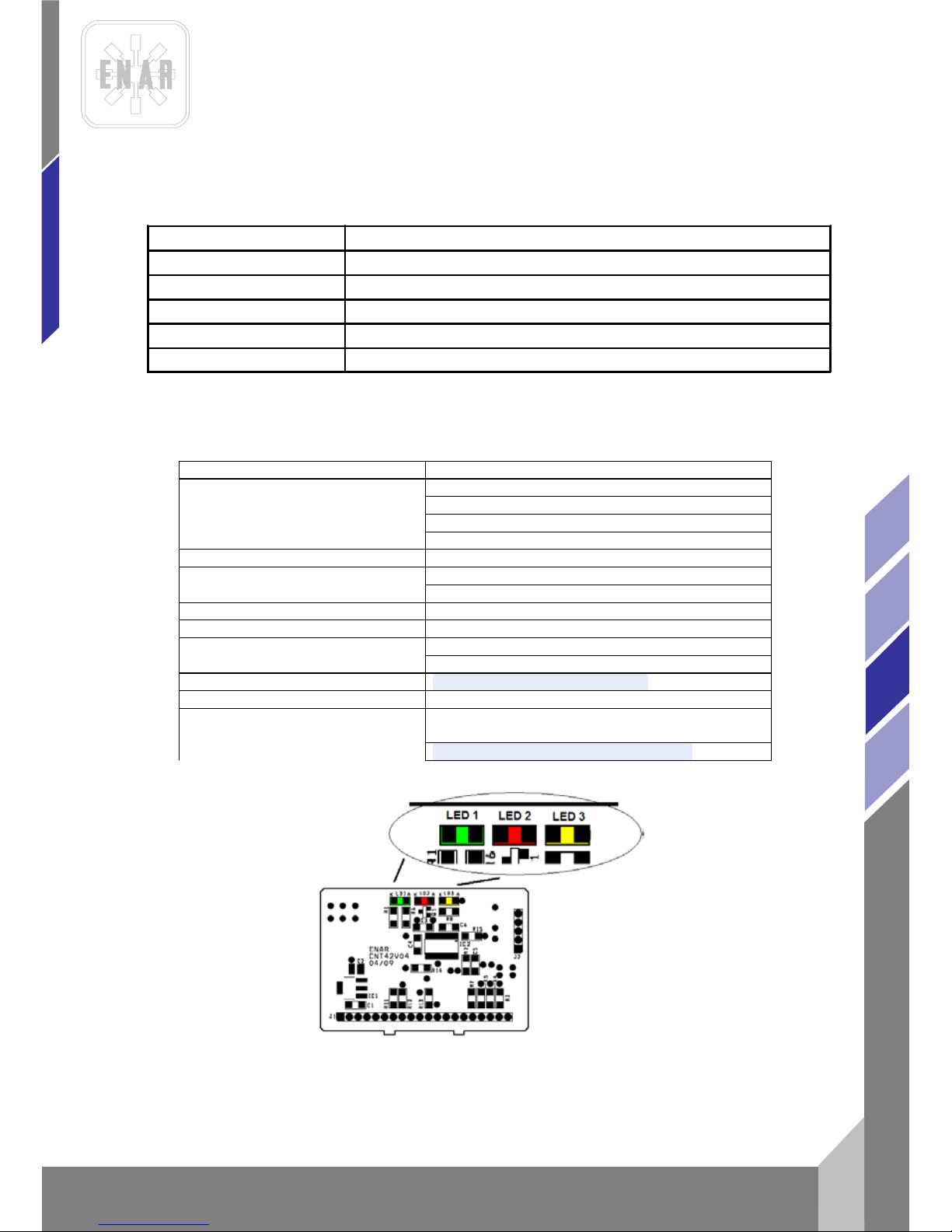
5.3 CONVERTISSEURS ELECTRONIQUES
PROBLÈMES
CAUSES
Ne foncionne pas
Vérifier s’ il y a du courant
led verte (1) OFF
Prise en mauvais état
Câble d’alimentation coupé
Convertisseu r ab îmé
Led rouge(2) ON
Stator aiguille brûlé
Convertisseu r ab îmé
Surcharge>30A
Led rouge (3) ON
Surcharge instantanée> 60A
Aiguille défect ue use
Court-circuit entre phases moteur
L’aiguille fonctionne bien mais
chauffe
Vérifier la tension d’entrée du convertisseur.
Vérifier le fonctionnement du ventilateur.
PROBLEME CAUSE/SOLUTION
Le moteur ne fonctionne pas
1.- Vérifier le niveau d'essence.
2.- Vérifier la position du robinet d'essence.
3.- Vérifier la position du levier .
Le moteur électrique surchauffe
1.- Nettoyer les ouvertures d'entrée et de sorti e d'air
2.- Les aigui lles vibrantes connectées dépassent la capacité du convertisseur
Page 41
CONVERTISSEURS DE FREQUENCE
fr
14
AFG, AFD, AFE
6 L’APPROVISIONNEMENT EN PIECES DETACHEES
6.1 INSTRUCTIONS POUR COMMANDER LES PIECES DETACHEES
1. Inclure dans toute commande de pieces détachées LA REFERENCE DE LA PIECE QUI
CORRESPOND A CELLE DE LA VUE ECLATEE AINSI QUE LE NUMERO DE SERIE DE
L'APPAREIL.
2. La plaque d'identification avec les numeros de serie et le modèle se trouve sur la partie
supérieure de la carcasse en plastique du moteur, sur la transmission et pour ce qui est de l'aiguille,
le numero est gravé à l'extérieur, sur la bouteille.
3. Fournir les instructions de transport correctes, en incluant le transporteur et la route désirée
ainsi que la direction complète du consignataire.
4. Ne pas retourner de pièces détachées à l'usine à moins d'y être expressemment autorisé,
sachant que même les retours autorisés doivent être effectués en port dû.
6.2 INSTRUCTIONS POUR FAIRE JOUER LA GARANTIE
1. La garantie a une durée de validité de 1an à partir de la date d'achat de la machine.La
garantie couvre les pièces qui présentent un défaut de fabrication. En aucun cas la garantie ne
couvrira les dégâts occasionnés par une mauvaise utilisation de l'appareil. La main d'oeuvre et les
frais courront toujours à charge du client.
2. Il faut envoyer , pour toute sollicitude, l'appareil à ENARCO,S.A. ou un REPARATEUR
AGREE,en indiquant toujours l'adresse et le nom complet du consignataire.
3. Le départament de S.A.V. notifiera inmédiatement si la garantie joue et si client le demande il
sera en mesure de produire d'un rapport technique détaillé sur les causes de la panne et sur les
opérations à effectuer pour réparer l'appareil.
4. Tout appareil qui aurait été manipulé par un réparateur ou un personnel non agrée par
ENARCO, S.A ne pourra être garanti.
NB : ENARCO, S.A. se reserve le droit de modifier toutes données de ce manuel sans préavis..
Page 42

FREQUENZ UMFORMER
1
de
AFG, AFD, AFE
INHALTSVERZEICHNIS
1 VORWORT 2
2 DATEN 3
2.1 DATEN FREQUENZ UMRORMER 3
2.2 FREQUENZ UMFORMER MIT BENZIN MOTO 6
3 EINSATZVORAUSSETZUNGEN 6
3.1 ARBEITSPLATZ 6
3.2 ELEKTRISCHE UND PERSÖNLICHE SICHERHEIT 7
3.3 ANWENDUNG UND WARTUNG 7
3.4 WARTUNG 8
3.5 BESONDERE SICHERHEITSVORSCHRIFTEN 8
4 INBETRIEBNAHME 9
4.1 ANSCHLUSS DER RÜTTELLANZEN AN DEN UMFORMER 9
4.2 ANSCHLUSS DES UMFORMERS ANS STROMNETZ 9
4.3 BENZIN MOTOR
10
4.4 REGELMÄSSIGEWARTUNG
10
4.5 WARTUNG MIT BENZIN MOTOR
11
4.6 ÜBERPRÜFUNG 11
4.7 LAGERUNG 11
4.8 TRANSPORT 11
4.9 WARTUNG DES RÜTTELLANZE 12
5 FEHLERSUCHE SCHALSCHEMA 12
5.1 ELEKTRISCHEM UMFORMER 12
5.2 BENZIN MOTOR 12
5.3 ELEKTRONISCHE UMFORMER 12
6 ANWEISUNGEN FÜR DIE BESTELLUNG VON ERSATZTEILEN 14
6.1 ANWEISUNGEN FÜR DIE BESTELLUNG VON ERSATZTEILEN 14
6.2 ANWEISUNG FÜR DIE GARANTIEGEWÄHRUNG 14
Page 43

FREQUENZ UMFORMER
de
2
AFG, AFD, AFE
1 VORWORT
Vielen Dank für Ihr Vert ra ue n in die Ma rk e ENAR.
Wir empfehlen Ihnen, die Sicherheits- , Insta nd hal t un gs- und Anwendungsvorschriften in diesem
Handbuch zu lesen, damit Sie Ihre ENAR - Anlage voll ausnützen können.
Beschädigte Teil e müs s en um ge he nd ausgewechselt wer den, um größere Problem e zu verm ei de n.
Die Einsatzbereiche der Maschine nehmen zu, wenn Sie den Anweisungen dieses Handbuchs
folgen.
Ihre Anmerkungen und Vorschläge bezüglich unserer Maschinen nehmen wir gerne entgegen.
Page 44

FREQUENZ UMFORMER
3
de
AFG, AFD, AFE
2 DATEN
2.1 DATEN FREQUENZ UMRORMER
TYP
Mechanischer um former:
Besteht aus einem Motor und einem Generator mit magnetischem Rotor (ohne Bürsten).
Elektronischen umformer:
Besteht aus einem elektronischen Frequenzumrichter und Transformator. Die gesamte Baugruppe
mit Zwangsbelüftung.
EINSATZ
Wandelt die Eingangsspannung und -frequenz in eine Ausgangsspannung von 42 V-200 Hz
dreiphasig um, um die Rüttelanlage mit dem Motor anzuschliessen, ref. ENAR M35AF, M5AF,M6AF
und M7AF
NETZKABEL
5 m lang, Standardmaschine mit einem Stecker Typ CE, Isolierung 1 KV.
ANSCHLUSSMÖGLICHKEITEN
Die Summe des Verbrauchs bei Last der angeschlossenen Rütterlanze darf die in der Tabelle der
elektrischen Dat en an gegebene Ausgangs st rom stärke nicht übers chr eit e n.
MODELL
DREPHASIG: AFE 2000 P, AFE 1000 P
EINPHASIG: AFE 2000M P, AFE 1000M P
GEHÄUSE
HOCHRESISTENTER KUNSTSTOFF mit einm Schutz gegen Staub und Spritzer
MODELL
DREIPHASIG: AFE 200 0 T, AFE 2500
EINPHASIG: AFE 2000 MT, AFE 2000MT 230v
GEHÄUSE
SPEZIELLER EISENSCHUTZBUGEL MIT SCHUBKARREN MIT RÄDERN .
MODELL
DREIPHASIG : AFE3500, AFE4500, A FE60 00
GEHÄUSE
SPEZIELLER EISENSCHUTZBUGEL MIT SCHUBKARREN MIT RÄDERN
Page 45
FREQUENZ UMFORMER
de
4
AFG, AFD, AFE
* in 1 m Entfernung des Konverters, K = 2
Modell
Gewicht
Kg
Anzahl
Ausgänge
Max. Anschlussmöglichkeiten
M38A
M5AF
M6AF
M7AF/M8AF
AFE 2000P
25
2
2
2
1
1
AFE 1000P
15
1
1
1
1
-
AFE 2000MP
27
2
2
2
1
1
AFE 1000MP
17
1
1
1
-
-
AFE 2500T
34 3 5 3 2
2
AFE 3500
70 4 8 4 3
2
AFE 4500
74 4 9 5 4
4
AFE 6000
83
4
10
6
5
4
AFE 1000MT
20
1
1
1
-
-
AFE 2000T
28
2
2
2
1
1
AFE 2000MT
30
2
2
2
1
1
AFE 2000MT 230V
30
2
Dieser Konverter verwendet 230 V
ELEKTRISCHE DATEN
Schalldruck
L
PA
*
MODELL
EINGANG
AUSGANG
KW
AMP V KW
AMP
V
AFE2000 P
2,8KW
4,0A
400V 3-/50Hz
1,6KVA
23 A
42V 3-/200Hz
64
AFE1000 P
1,8KW
2,5A
400V 3-/50Hz
1,0KVA
13 A
42V 3-/200Hz
62
AFE2000M P
2,0KW
9A
230V 1-/50Hz
1,6KVA
23 A
42V 3-/200Hz
64
AFE 2000M P
60Hz
2,0KW 9A 230V 1-/60Hz 1,6KVA 23 A 42V 3-/200Hz
64
AFE 2000MT
230V
2,0KW 9A 230V 1-/60Hz 1,6KVA 23 A 230V 3-/200Hz
64
AFE1000M P
1,3KW
6A
230V 1-/50Hz
1,0KVA
13 A
42V 3-/200Hz
62
AFE2000T
2,8KW
4,0A
400V 3-/50Hz
1,6KVA
23 A
42V 3-/200Hz
64
AFE2000MT
2,0KW
9A
230V 1-/50Hz
1,6KVA
23 A
42V 3-/200Hz
64
AFE1000MT
1,3KW
6A
230V 1-/50Hz
1KVA
13A
42V 3-/200Hz
62
AFE2500T
4KW
6A
400V 3-/50Hz
2,5KVA
35A
42V 3-/200Hz
66
AFE3500
6KW
8A
400V 3-/50Hz
3,5KVA
50 A
42V 3-/200Hz
68,5
AFE4500
7KW
10A
400V 3-/50Hz
4,5KVA
61 A
42V 3-/200Hz
70
AFE6000
8KW
11A
400V 3-/50Hz
6KVA
82 A
42V 3-/200Hz
70
Page 46
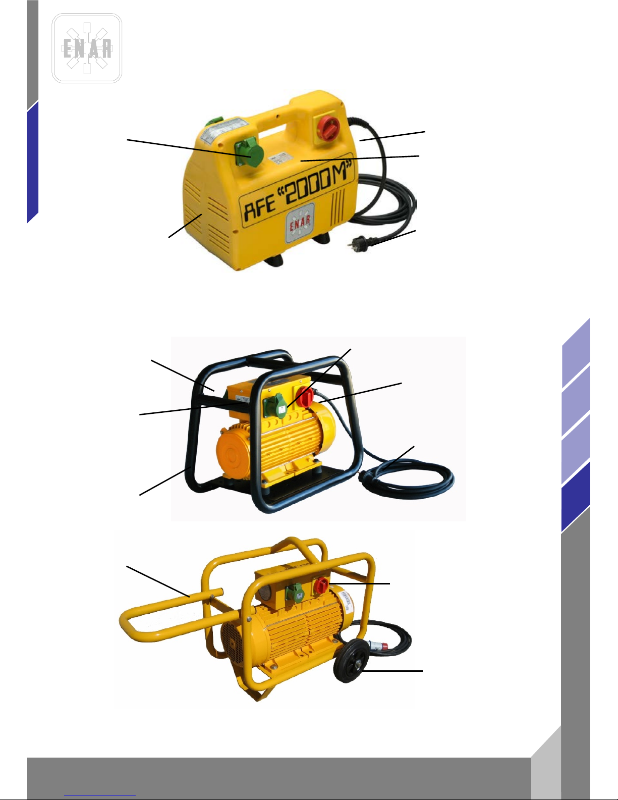
FREQUENZ UMFORMER
5
de
AFG, AFD, AFE
BUCHSE ZUM ANSCHLUSS DES
VIBRATORS 200 Hz < 50 V
SCHALTER (STARTSTOP)
TYPENSCHILD
STECKER 2F+E o
3F+E UND 5M
KABEL
KUNSTSTOFFGEHÄUSE
AFE 2000P, AFE 2000MP, AFE 1000P, AFE 1000MP
PLASTIC HOUSING
ANSCHLUSSDOSE
TYPENSCHILD
RUNDSTAHL
VERBUNDEN
STECKER 2F+E o 3F+E UND
5M KABEL
SCHALTER (STARTSTOP)
BUCHSE ZUM ANSCHLUSS DES
VIBRATORS 200 Hz < 50 V
AFE 2000T, AFE 2500T, AFE 2000MT, AFE 1000MT TUBULAR FRAME
SCHALTER (STARTSTOP)
AFE 3500, AFE 4500 AND AFE6000 CARRIEGE WHEEL FRAME
RÄDER
GRIFF
Page 47
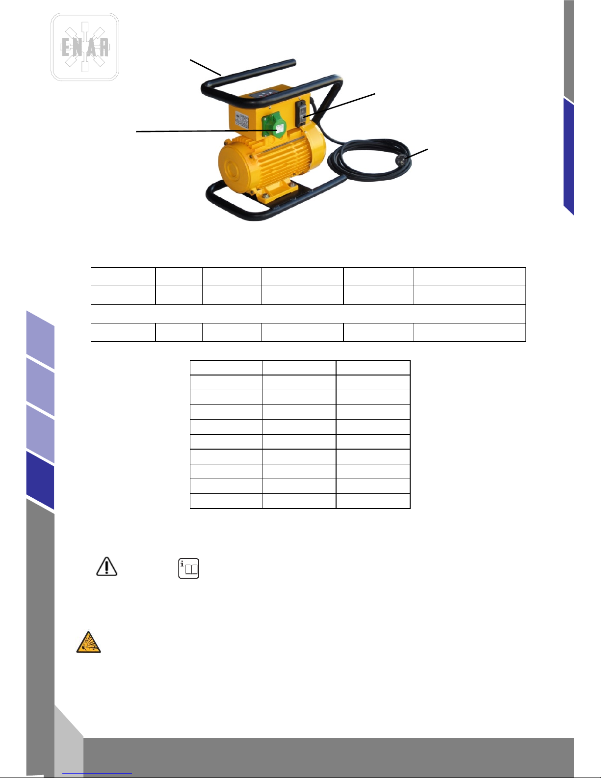
FREQUENZ UMFORMER
de
6
AFG, AFD, AFE
2.2 FREQUENZ UMFORMER MIT BENZIN MOTO
MODELO PESO SALIDAS MOTOR GENERADOR AGUJAS
AFGH2000 38Kg 2 5.5HP HONDA 42V / 200HZ
2M5AF / 1M6AF / 1M7AF/
1M8AF
DIESEL
AFDY2000 48Kg 2 4,7 HP YANMAR 42V / 200HZ
2M5AF / 1M6AF / 1M7AF/
1M8AF
MODELL GX 160K1 YANMAR
ZEITEN 4, 163cc 4, 211cc
LEISTUG 5.5HP/3600rpm 4.7HP/3600rpm
PAAR 1.1Kgm/2500rpm 1.25Kgm/2800rpm
RPM 3900rpm 3600rpm
EINGESCHALTET TRANSISTOR INJECTION
BRENNSTOFF GASOLINA DIESEL
TANK 3.61 2.51
GEWICHT 15Kg 26Kg
ÖL 0.61 0.81
3 EINSATZVORAUSSETZUNGEN
ACHTUNG! BITTE LESEN UND VERSTEHEN SIE JEDE ANWEISUNG.
3.1 ARBEITSPLATZ
HALTEN Sie Ihren Arbeitsplatz sauber und beluchtet.
GERÄTE NICHT VERWENDEN in explosiven Atmosphären, wie in der Gegenwart von leicht
enzündbaren Flüssigkeiten, Gasen oder Staub.
6
SCHALTER
STECKDOSE
STECKER 2F+E o 3F+E
UND 5M KABEL
RAHMEN
Page 48
FREQUENZ UMFORMER
7
de
AFG, AFD, AFE
Zuschauer, Kinder, und Besucher während des Betriebs der Maschine FERNHALTEN.
3.2 ELEKTRISCHE UND PERSÖNLICHE SICHERHEIT
GERÄTE MIT ERDUNG MÜSSEN an einem genehmigten Stecker angeschlossen werden. Der
Sockelstecker muss auch nach allen Normen genehmigt sein.
NICHT ÄNDERN ohne Zulassung den Stecker oder die Erdung.
KEINERLEI Anschlußadapter verwenden!
PRÜFEN Sie mit einem qualifizierten Arbeiter, falls Sie bei der Installation oder der Erdung zweifeln.
VERMEIDEN Körperkontakt mit geerdeten Oberfláchen.
Geräte NICHT Regen oder Feuchtigkeit AUSSETZEN.
DAS KABEL NICHT FORCIEREN.
DAS KABEL NIE FÜR DEN TRANSPORT DES GERÄTES VERWENDEN.
NIE AM KABEL ZIEHEN UM AUSZUSTECKEN.
BESCHÄDIGTE KABEL AUSWECHSELN.
FÜR ANWENDUNGEN IN FREIEN verwenden Sie bitte ein Verlängerungskabel.
SEIEN SIE WACHS A M bei der Arbei t und nut z en Si e Ihr en ges un den Mens c h enverstand.
NICHT VERWENDEN wenn Sie müde sind oder unter Einfluß von Alkohol, Drogen oder
Medikamenten stehen.
TRAGEN SIE ARBEITSKLEIDUNG .
KElNE WEITE KLEIDUNG ODER SCHMUCK TRAGEN.
LANGE HAARE ZUSAMMENBINDEN.
HALTEN Sie Haaren, Kleidung und Handschuhe FERN von beweglichen Teilen.
VERGEWISSERN SIE SICH , daß die Maschine vor dem Einstecken ausgeschaltet ist.
ENTFERNEN von Schlüsseln oder Einstellungsgeräten vor Inbetriebnahme der Maschine.
NICHT DAS EIGENE KRAFTLIMIT ÜBERSCHREITEN.
VERMEIDEN Sie eine anormale Körperhaltung und prüfen Sie Ihre Fußhaltung, damit Sie in
unvorhergesehenen Situationen nicht die Kontrolle verlieren.
VERWENDEN Sie die Sicherheitsausrüstungen.
Immer AUGENSCHUTZ VERWENDEN.
3.3 ANWENDUNG UND WARTUNG
VERWENDEN eine stabile Halterung des Körpers und des Gerätes .
FORCIEREN SIE DAS GERÄT NICHT.
WAHLEN SIE FÜR JEDE ARBEIT DAS ENTSPRECHENDE GERÄT.
DAS GERÁT NICHT VERWENDEN, wenn der Schalter nicht auf OFF gestellt werden kann.
LAGERN Sie das Gerät nicht in der Nähe von unbefugtemPersonal oder Kindern.
WARTEN sie das Gerät sorgfältig.
PRÚFEN SIE das Spiel von beweglichen Teilen ,ob Teile kaputt sind, und jeden Zustand, der Einfluß
auf die Funktionsweise der Maschine haben könnte. Falls die Maschine beschädigt ist, muß Sie vor
dem nächsten Gebr auc h ge w art et w erd en.
GEBRAUCHEN Sie nur vom Hersteller empfohlenes Zubehör für Ihr Gerät. Ersatzteile, die nicht
passen, oder Zubehör, das nicht für das Gerät nicht geeignet ist, könnten gefährlich sein, wenn man
sie bei einem anderen Gerät montiert.
Page 49
FREQUENZ UMFORMER
de
8
AFG, AFD, AFE
3.4 WARTUNG
DIE WARTUNG MUSS von qualifizierten Personen durchgeführt werden.
VERWENDEN Sie nur identische Ersatzteile für die Wartung.
BEACHTEN Sie bitte die Anweisungen im Wartungsteil der Bedienungsanleitung.
3.5 BESONDERE SICHERHEITSVORSCHRIFTEN
Der Motor darf nur für Arbeiten benutzt werden, wie in diesem Buch erwähnt.
Bevor Sie den Moto r an das Stromnetz anschließen, überzeugen Sie sich, daß Spannung und
Frequenz mit den Angaben auf dem Typenschild der Anlage, daß sich auf der Oberseite des
Kunststoffgehäuses befindet, übereinstimmen. Vergewissern Sie sich vor Arbeitsbeginn, daß die
Schrauben des Gehäuses angezogen sind.
Bitte vergewissern sie sich, daß am Boden liegende Kabel nicht von Lastkraftwagen oder Maschinen
gewalzt werden .
Schließen Sie die biegsame Welle nicht an den laufenden Motor an.
Manipulieren Sie nicht bei laufendem Motor oder ohne Übersetzung am Motor herum.
Arbeiten Sie nicht bei beschädigter Welle (Übersetzungsgetriebe) oder Flasche (Rüttellanze) mit
dem Motor. Er würde sonst heißlaufen.
Die Maschine nicht benutzen, wenn das Kunststoffgehäuse des Motors kaputt ist.
Unbefugtem und unerfahrenem Personal ist das Bedienen des Motors oder seiner Anschlüsse zu
untersagen.
Halten Sie Luftzufuhr und -abzug frei.
Halten Sie den Motor in einem sauberen und trockenen Zustand.
Achten Sie auf den passenden Querschnitt und einen einwandfreien Zu st a nd des K ab els.
Unterbrechen Sie bei jeder Art von Eingriff die Verbindung zum Stromnetz.
Überzeugen Sie sich beim Anschluß an einen Generator davon, daß Spannung und
Ausgangsfrequenz stabil und korrekt sind und, daß die Leistung die Richtige ist. Die
Versorgungsspannung des Motors darf nicht mehr als 5% von der auf dem Typenschild
angegebenen ab w eichen.
Der Wert des akustisc he n Drucks liegt unter 70 dB. Im Fall ei n er Übe rrschreitung dies es Werts muß
eine Lärmschut zanl a ge ein gesetzt werden .
Wenn die Betonierung und das dazu gehörende Rütteln beendet sind (oder bei Pausen), bitte den
Motor vom Stromnetz nehmen und die Maschine an einen sicheren Ort stellen.
Der laufende Motor muss nicht befassen werden!.
Anwendung von einer Anlager mit Benzin Motor :
- Bitte lesen Sie ausführlich diese Gebrauchsanweisungen bevor Arbeitsbeginn.
- Nicht in geschlossenen Räume arbeiten, Die Abgase des Motors können schnell giftig
sein !
- Bei Tanken mit heissem Motor, Bitte warten auf Kühlung während mindestens 2
Minuten.
Während der Arbeit mit diesem System kann gelegentich der zulässige Lärmpegel von 95dB. In
diesem fall mub einen schutzhelm getragen werden.
ZUSÄTZLICH MÜSSEN DIE IN IHREM LAND GELTENDEN VORSCHRIFTEN BEFOLGT WERDEN.
Page 50
FREQUENZ UMFORMER
9
de
AFG, AFD, AFE
4 INBETRIEBNAHME
Lesen Sie hierzu Punkt 3 EINSATZVORAUSSETZUNGEN
4.1 ANSCHLUSS DER RÜTTELLANZEN AN DEN UMFORMER
Der Umformer ist mit einer Anschlußvorrichtung für Rüttellanzen ausgestattet.
Anschlußmöglichkeiten:
Der Verbrauch der unter Last angeschlossenen Lanzen darf die in der Tabelle der elektrischen
Daten angegebene Ausgangsstromstärke nicht überschreiten.
4.2 ANSCHLUSS DES UMFORME RS A NS STROMNE T Z
Den Schalter des Umformers vor dem Anschließen ausschalten. Wenn bei der Auftragserteilung
nichts Gegenteiliges gewünscht wird, werden die Modelle AFE 2000 und AFE 1000, der
Frequenzumformer, ab Werk für ihren Einsatz bei dreiphasigem Strom ab 380 V 50 Hz eingestellt.
Die Modelle AFE 2000M und AFE 1000M werden ab Werk für einphasigen Strom ab 220 V 50 Hz
eingestellt.
ABSCHALTEN DER ANLAGE
Zunächst die Rüttellanzen durch Betätigen des entsprechenden Schalters abschalten. Anschließend
durch Betätigu ng des entsp rechenden Schalt ers de n Um fo rm er aus s ch alten. Zuletzt den
Netzstecker aus der Steckdose des Stromnetzes ziehen.
ERDUNG
Um den Benutzer vor Stromschlägen zu schützen, muß der Motor korrekt geerdet werden.
Die UMFORMERmotoren sind mit dreiphasigen Kabeln (einphasig) oder vierphasigen Kabeln
(dreiphasig) un d den ent s pr ec henden Steckern ausgerüstet. Für den Anschluß an den Motor sind
die passenden Steckersockel mit Erdungsanschluß zu verwenden (Bild 1). Wenn diese nicht zu
Verfügung stehen, ist vor der Verbindung der Leitungen ein Adapter mit Erdungsleitung zu
verwenden, wie in Bild 2 abgebildet.
VERLÄNGERUNGSKABEL
Nur dreiphasige Verlängerungskabel mit Erdungsanschluß verwenden, bei denen sowohl Stecker
als auch Steckdose mit drei Leitern aus-rüstet sind, und in die der am Motor angebrachte Stecker
passt.
Keine beschädig ten o der abge nützten Kabel verwenden.
Keine schweren Lasten über die Kabel ziehen.
Zur Ermittlung des Querschnitts folgendermaßen vorgehen:
VERFAHREN ZUR BESTIMMUNG DES BEI DER KABELVERLÄNGERUNG NOTWENDIGEN
QUERSCHNITTS
Die folgenden Daten sind zu überprüfen und der größte Kabelquerschnitt festzustellen.
1. Der Ohmische Widerstand und der Induktive Widerstand des Kabels bei einem zulässigen
Spannungsverlust von 5%, cos.phi = 0,8, mittels Frequenz- und Spannungskurve.
z. B: Nennspannung :...............................230 V 50 Hz
Nennstromstärke :............................10 A
Kabellänge:......................................100 m
Einbeziehung in die Kurve mit dem Produkt: Stromstärke x Länge = 10 x 100= 1000 Am
Page 51
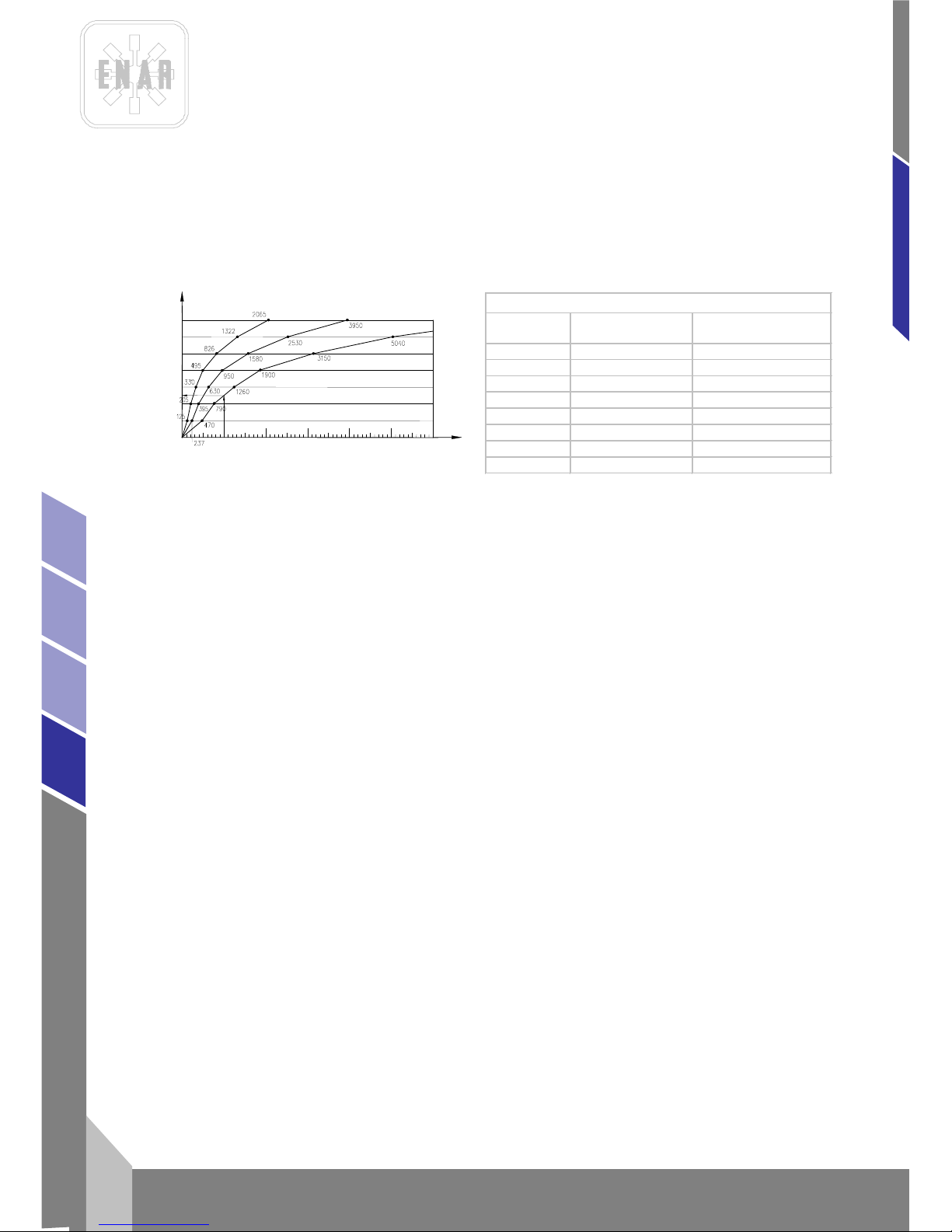
FREQUENZ UMFORMER
de
10
AFG, AFD, AFE
Wir erhalten einen Querschnitt von 4 mm.
2. Die zulässige Erhitzung des Kabels nach VDE (Tabelle für den mindesterforderlichen
Querschnitt):
z. B: Für 10 A beträgt der Querschnitt, laut Tabelle für 15 A oder weniger, 1 mm.
Also beträgt der gewählte Querschnitt 4 mm, von den zwei Tests stets den größeren Querschnitt
wählen.
4.3 BENZIN MOTOR
Bitte lesen Sie die Gebrauchsanweisungen vom Motor für die Wartung und für den Start.
Nicht arbeiten in Plätze, die keine gute Lüftung haben.
Bitte vergewissern SIe sich, dass es keine Brennstoff in der nähe vom Auspuff gibt und dass es
Benzin ImTank gibt.
Bitte der Kabel mit Hochspannung nicht berühren um einen elektrischem Schock zu vermeiden.
Mit dem Gashebel die Umdrehungen einstellen bis die Anlage die richtige Schwingungen erreicht
(SAE 10W40).
1. ELEKTRISCHEM GENERATOR
Uberprüfen Sie, dass die alle Kabel sich in umwandfreien Zustand befindet.
2. Falls Sie einen Fehler bemerken, die eine sicherliche Anwendung gefährlichen, die Anlage bitte
stoppieren und die entsprenchende Wartung machen.
4.4 REGELMÄSSIGEWARTUNG
1. Arbeiten an den elektrischen Teile n dür fen nu r vom Fac hm an n dur chg eführt werden.
2. Während der Wartungsarbeiten muß sichergestellt sein, daß die Verbindung zum Stromnetz
unterbrochen ist.
3. Bei allen Wartungsarbeiten Originalersatzteile verwerden.
4. Ein regelmäßiges Schmieren des Lagers des Umformers ist nicht erforderlich.
5. Der elektrische Erdleiter (Grün-Gelb) muß länger sein, damit er im Falle einer Kabelbremse
nicht als erster unte rbr och en wir d. Na c h Reparaturen oder W artun gsarbeiten den Stromfluß durch
das Erdkabel kontrollieren.
6. In regelmäßigen Abständen die Lüftungsöffnungen an der Vorder- und Hinters eite des Mot o rs
reinigen, um ein Übe rhit z en zu verm ei d en.
7. Nach Service- und Wartungsarbeiten alle Teile der Sicherheitsvorrichtungen wieder richtig
zusammenbauen.
8. Ungefähr alle 40 Betriebsstunden die Halterungsschrauben am Gehäuse überprüfen.
Leitung
Höchst bel a stung Sicherung höchstens
1 15 10
1,5 18 10/3-16/12,5 26
20
4 34 25
6 44 35
10 61 50
16 82
63
25 108 80
Minde stquerschnitte nach VDE – Norm
INTENSIDAD NOMINAL X LARGO DE LÍNEA (A m)
SECCIÓN DE LA LÍNEA EN mm
2
2,5
1,5
10
4
6
25
16
6000
3000
1000
0
2000
4000
5000
115 V
230 V
380 V
Page 52

FREQUENZ UMFORMER
11
de
AFG, AFD, AFE
9. Je nach Einsatzbedingungen die Maschine alle 12 Monate, oder öfter, in einer
Vertragswerkstatt überholen lassen.
4.5 WARTUNG MIT BENZI N MOTOR
1. Täglich (8 Stunden)
Motor sauber machen, Schrauben kontrolliereen, mit Benzin/Öl Mischung wieder tanken.
2. Wochlich (50 Stunden)
Zündkerze putzen und Toleranz kontrolieren, Luft-und-Benzinfilt er rei nin gen.
3. Monatlich (200 Stunden)
Olfilter reiningen, Zündkerzen kontrollieren.
Wir empfehlen den Kugellager zu kontrollieren, schmieren und wenn er defekt ist , müssen Sie
einen neuen montieren.
4. 500 Stunden
Der Vergaser reiningen, der Zylinderkopf reiningen, die Ventile einstellen.
5. Für alle Wartungen , muss man nur Originale Ersatzteilen benutzen.
6. Nach Service- und Wartungsarbeiten alle Teile der Sicherheitsvorrichtungen wieder richtig
zusammenbauen.
7. Je nach den Einsatzbedingungen alle 12 Monate oder öfter in einer Vertragswerkstatt
überholen lassen.
8. Nicht rauchen beim Tanken, nicht tanken in der Nähe von einem Gefahrsquelle.
Benzin eingang zu machen beim Tanken, 25:1 Mischung benutzen, Benzin einspritzungen
vom Motor reiningen.
9. Bitte die Gebrauchsanweisungen des Motors lesen. Im leeriauf mub der motor 3000 u.p.m.
nicht uberschrei te n (re guliert nach der monta ge) .
4.6 ÜBERPRÜFUNG
1 Arbeitsbeginn ist zu überprüfen, ob alle Betriebs - und Sicherheitsvorrichtungen einwandfrei
funktionieren.
2 In regelmäßigen Abständen den Zustand der Netzkabel überprüfen.
3. Stets die Anschlußspannung überprüfen.
4 Sobald Fehler auftreten, die den sicheren Umgang der Maschine gefährden, muß die Arbeit
abgebrochen, und die entsprechende Instandsetzung durchgeführt werden.
5. Der Umformer darf nur zusammen mit allen Sicherheitsvorrichtungen verwendet weden.
6. Sobald Defekte an den Sicherheitsvorrichtungen oder andere Defekte auftreten, die den
sicheren insatz der Maschine nicht mehr gewährleisten, ist unverzüglich die dafür
verantwortlic he Pers on zu benachrichtigen .
4.7 LAGERUNG
Den Umformer stets an einem sauberen, trockenen und geschützten Ort aufbewahren, wenn er für
eine längere Zeit nic ht be nut z t werd en sol l.
4.8 TRANSPORT
In Transportfahrzeugen ist der Motor gegen Verrutschen und Umstürzen sowie gegen Stöße zu
sichern.
Page 53
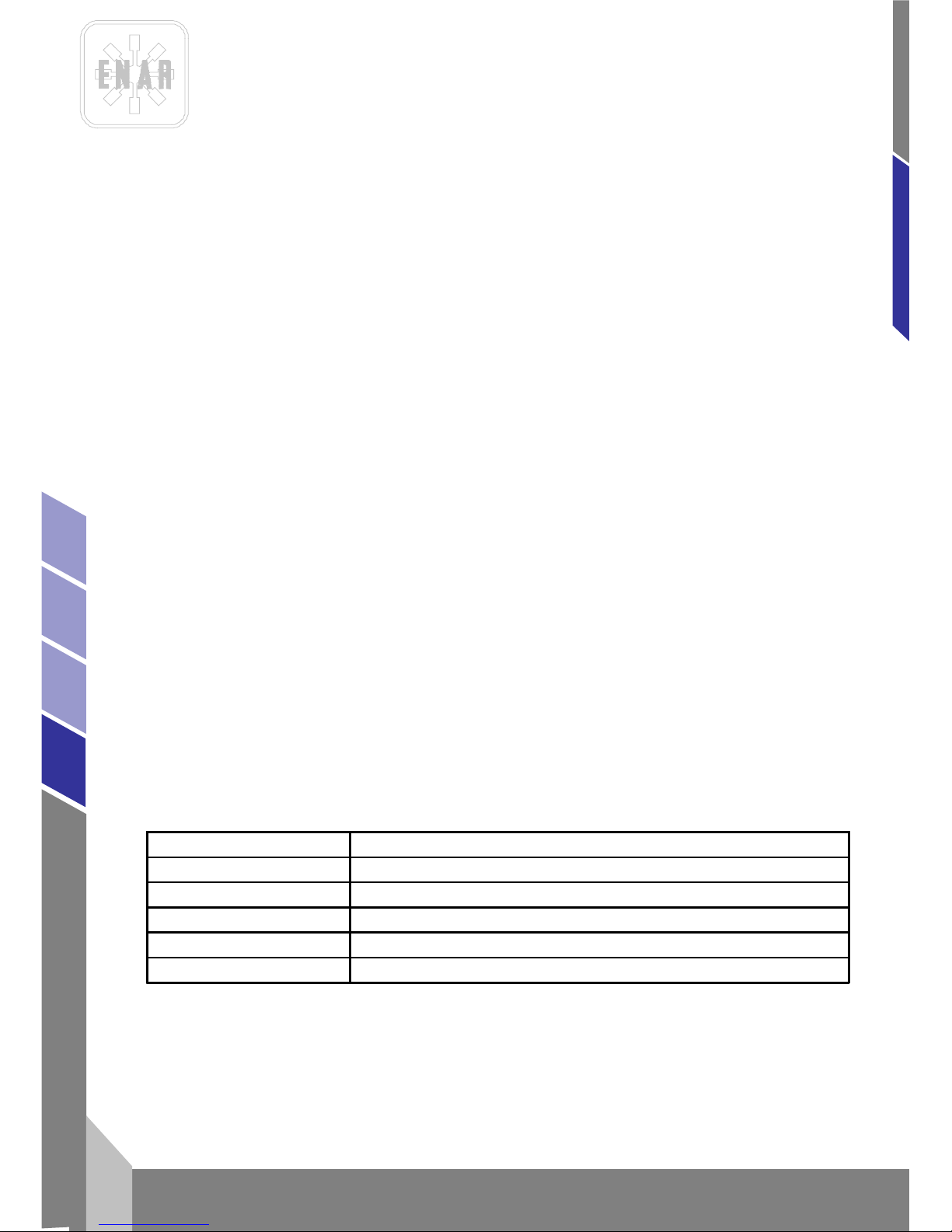
FREQUENZ UMFORMER
de
12
AFG, AFD, AFE
4.9 WARTUNG DES RÜTTE LLANZ E
Siehe Handbuch zu Übers e t zungsgetriebe und Lan ze (M965-993).
5 FEHLERSUC H E SCHALSCHEMA
5.1 ELEKTRISCHEM UMFORME R
PROBLEM URSACHE / LÖSUNG
Motor läuft nicht.......................................................Strom und Ansc hluß überprüfen
Stecker in schlechtem Zustand
Schalter kaputt
Motor läuft normal, aber läuft heiß.........................Öffnungen für Luftein- und austritt am
Gehäuse reinigen.
Angeschloßene Rüttellanzen für die Kapazität des
Umformers ungeeignet.
Motor läuft langsam u nd läuf t heiß... . ....... ..... .... .... Spannung der elektrischen Kraft überprüfen
Vielleicht läuft der Motor auf zwei Phasen.
Daten des Verlängerungskabels überprüfen
Überprüfen Sie die Spannung am
Spannungsumsteller.
Motor ist zu laut........................................................Lager defekt
Vielleicht reibt der Anker am Ständer
Gehäuse kaputt oder Schrauben locker
5.2 BENZIN MOTOR
PROBLEM URSACHE/LÖSUNG
Der Motor geht nicht
1.- Gibt es Ol und B enzin im Tank?
2.- Mischung Eingang ist geöffnet.
3.- Lufthebel nachprüfen .
Elektromotor ist Heiss
1. - S t romspannung nac hpr üf en.
2.- Angschlossene Rüttellanzen für die Kapazität des umformers unggei gnet
Page 54
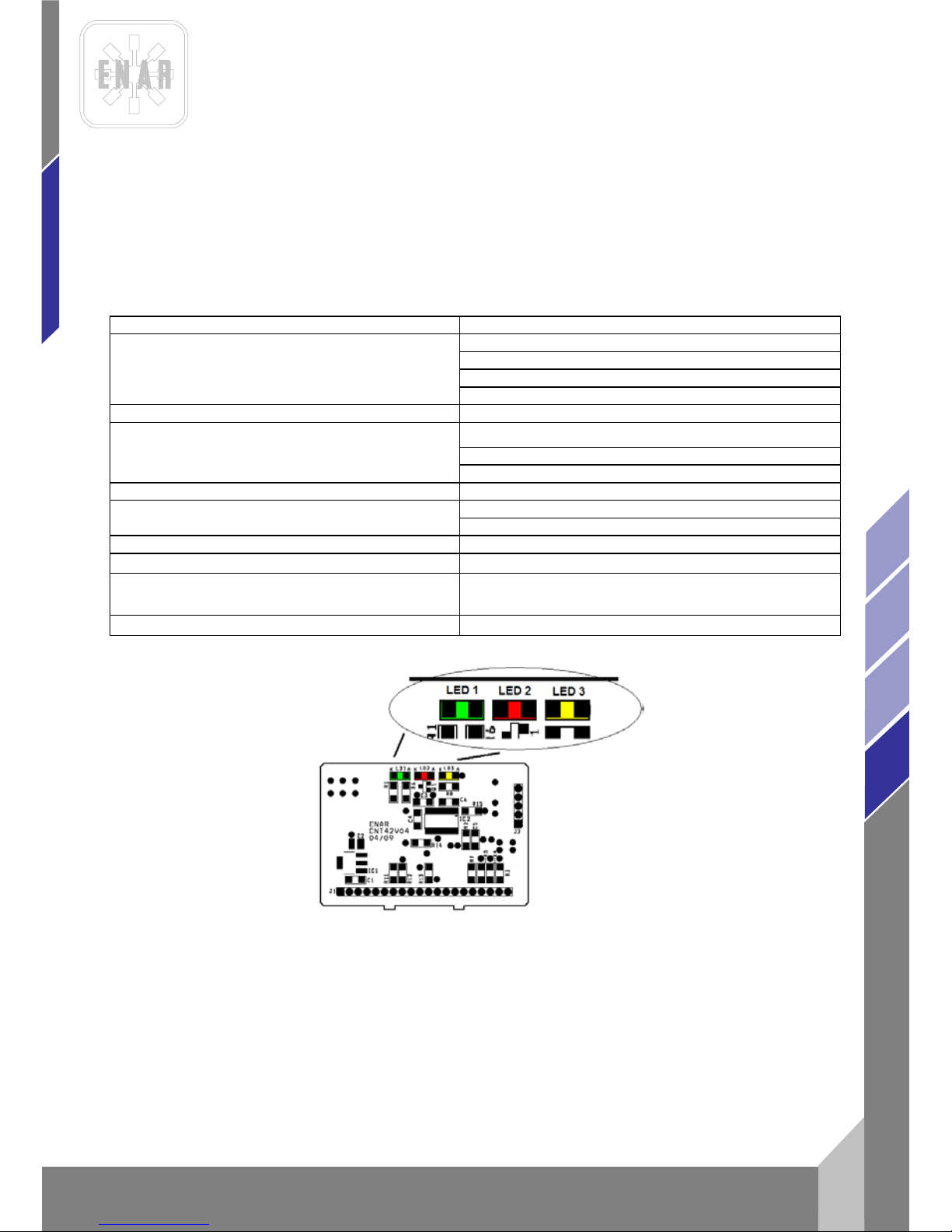
FREQUENZ UMFORMER
13
de
AFG, AFD, AFE
5.3 ELEKTRONISCHE UMFO RMER
PROBLEM
USACHE / LÖSUG
Funktioniert nicht, grüne Led (1) Aus.
Überprüfen ob Strom vorhanden ist.
Stecker defekt
Zuleitung unter bro ch en
Umformer defek t
Roter Led (2) an
Stator am Innenrüttler durchgebr ann t
Umformer defek t
Überlastung> 30A
Roter Led (3) an
Momentane Überlastung> 60A
Falsche defekt
Kurzschluss zwischen Motorp has en
Die Rüttelflasche funktioniert normal,
überhitzt aber
Überprüfen Sie die Eingangsspannung des
Umformers.
Funktionsprüfung des Ventilators.
Page 55
FREQUENZ UMFORMER
de
14
AFG, AFD, AFE
6 ANWEISUNGEN FÜR DIE BESTELLUNG VON ERSATZTEILEN
6.1 ANWEISUNGEN FÜR DIE BESTELLUNG VON ERSATZTEILEN
1. Bei allen Ersatzteilbestellungen muß DIE IN DER TEILELISTE AUFGEFÜHRTE
BESTELLNUMMER DES ERSATZTEILS angegeben werden . Es wird em pf o hlen , eben f alls DIE
FABRIKATIONSNUMMER DER MASCHINE anzugeben.
2. Die Kennplakette mit den Serien- und Modellnummern befindet sich auf der Oberseite des
Kunststoffgehäuses des Motors, beim Übersetzungsgetriebe und der Lanze steht die Nummer
außen.
3. Stets die korrekten Verladebedingungen angeben, einschließlich Beförderungsmittel, Adresse
und vollständigen Namen des Warenempfängers.
4. Die Ersatzteilrückgabe an die Fabrik darf nur mit schriftlicher Genehmigung derselben
erfolgen. Bei allen genehmigten Rückgaben sind die Portokosten zu entrichten.
6.2 ANWEISUNG FÜR DIE GARANTIEGEWÄHRUNG
1. Die Garantiezeit beträgt 1 Jahr ab dem Kaufdatum der Maschine. Die Garantie erstreckt sich
auf Teile mit Fabrikationsfehlern. In keinem Fall erstreckt sich die Garantie auf Schäden, die auf
den unsachgem äß en Gebrauch der Maschine zurückzuführen sind. Die Kosten für Techniker
und Versand sind stets vom Kunden zu tragen.
2. Bei allen Garantieanträgen IST DIE MASCHINE AN ENARCO, S.A. ODER AN EINE
VERTRAGSWERKSTATT EINZUSCHICKEN. Hierbei sind stets die vollständige Adresse und der
vollständige Nam e des W aren em pf ä ng ers an zug eben.
3. Die Kundendienstabteilung wird unverzüglich Mitteilung darüber ergehen lassen , ob die
Garantie übernommen wird, und gegebenenfalls einen technischen Bericht übermitteln.
4. Für Anlagen, an denen zuvor vom Personal manipuliert wurde, das nicht im Auftrag von
ENARCO, S.A. gehandelt hat, wird keinerlei Garantie übernommen.
NB: ZUSATZBEMERKUNG: ENARCO, S.A. BEHÄLT SICH DAS RECHT VOR, JEDE ANGABE IN DIESEM
HANDBUCH OHNE VORHERIGE MITT EILUNG ZU ÄNDERN.
Page 56
ENARCO, S.A.
DECLARACIÓN DE CONFORMIDAD
CONFORMITY CERTIFICATE ~ CERTIFICAT DE CONFORMITÉ
INSTEMMING VERKLARING ~ KONFORMITÄTS BESCHEINIGUNG
KONFORMITETS BEVIS ~ CERTIFICATO DE CONFORMIDADE ~ CERTIFICATO DI CONFORMITA'
ATITIKTIES DEKLARACIJA ~ CERTYFIKAT ZGODNOŚCI ~ СЕРТИФИКАТ СООТВЕТСТВИЯ
CERTIFICAT DE CONFORMITATE~ СЕРТИФИКАТ ЗА СЪОТВЕТСТВИЕ
ENARCO,S.A.
certifica que la máquina especificada
hereby certify that the equipment specified bellow ~ atteste que le equipment
verklaart hierbij dat onderstaand gespecificeerde ~ bescheinigt, da das Baugerät
bekræfter, at følgende maskine ~ certifica que o equipamento specificaçao
certifica che la macchina specificata ~ šiuo sertifikatu patvirtina, kad žemiau nurodytas prietaisas, t.y.
Zaświadcza, że wyszczególniona maszyna ~ Подтверждает, что нижеописанная машина
Certifica si declara ca echipamentul mentionat mai jos~ Потвърждаваме, че оборудването, описано по-долу
TIPO DE MAQUINA..............................................................CONVERTIDOR AFE, AFGH, AFDY
TYPE~TYPE~TYPE~TYP~TYPE~TIPO~TIPO~TIPAS~TYP~ТИП~TIP~ТИП CONVERTER AFE, AFGH, AFDY
CONVERTISSEUR. AFE, AFGH, AFDY
UMFORMER AFE, AFGH, AFDY
MODELO........................................................................................ AFE 1000/1000M/1000T/1000MT
MODEL~MODÈLE~MODEL~MODEL~MODEL~MODELO AFE 2000/2000M/2000T/2000MT
AFE 2500/3500/4500
MODELLO MODELIS~MODEL~МОДЕЛЬ~MODEL~МОДЕЛ AFGH2000/AFDY2000
CODIGO......................................................................................... 28250x/28260x/28270x/28280x
CODE~CODE~CODE~CODE~CODE~CODIGO~CODICE~KODAS~KOD 28290x/28310x/28510x/28520x
КОД~ COD ~ КОД 28530x/28540x/28550x
283500/283700
ha sido fabricada de acuerdo con las siguientes normas
has been manufactured according to the following standards ~ est produit conforme aux dispositions des directives ci-apres
in overeenstemming met de voldenge voorschriften gefabriceerd is ~ in übereinstimmung mit folgenden richtlinien hergestellt worden ist
er blevet fremstillet i overenstemmelse med følgende retningslinier ~ é fabricado conforme as seguintes normas
è stata fabbricata secondo le norme vigenti ~ buvo pagamintas laikantis toliau išvardintų standartų
została wyprodukowana zgodnie z następującymi normami ~ Произведена в соответствии со следующими нормами
este fabricat cu respectarea urmatoarelor standarde ~ е производено в съответствие със следните стандарти
2006/42/CE, 2000/14/CE, EN-60204
2014/35/EC*, 2014/30/EC*, 2002/95/EC*, 2002/96/EC*
*Aplicable for machines with electric motor
RESPONSABLE DOCUMENTACIÓN TÉCNICA………. Jesus Tabuenca (ENARCO, S.A. Burtina, 16, 50197 Zaragoza
Technical documentation responsible ~ Responsable of the Documentation Technnique ~ zuständigen technishen Dokumentation
Zaragoza, 01.10.2016
MANUFACTURER:
ENARCO, S.A.
C/Burtina 16
Plat. Logística PLAZA
50197 ZARAGOZA
SPAIN
Jose Luis Del Prim
General Manager
ENARCO,S.A.
 Loading...