


September 23nd 2016
DESCRIPTION :
Protection, control and
power supply box
for GMDSS system
Vessels equipped with an AC or DC onboard network
(external regulated filtered charger *)
TYPE : ICA - GMDSS 30 - RAE
(Deported platen A + V)
REFERENCE
: SEEL006715F
SERIAL NUMBER :
MANUFACTURER CODE : F 3645
CUSTOMER :
06715DAF
Page 1 / 14
OUTPUT NOMINAL
DC CURRENT
SPECIFIC
SPECIFICATIONS
AUTOMATIC
DETECTION
SYSTEM
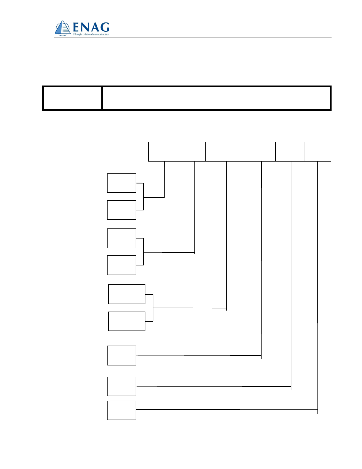
IDENTIFICATION
MATERIAL
I
CA - GMDSS 30 - RAE
Material identification procedure
²
I CA GMDSS 30 RAE
RAE
Idn
F
I
INTERNATIONAL
RULES
FRENCH
RULES
TYPE
CC
CA
ALTERNATING
CURRENT
DIRECT
CURRENT
GLOBAL MARITIME
DISTRESS and SAFETY
SYSTEM
SYSTEME MARITIME
de DETRESSE et de
SECURITE en MER
SMDSM
GMDSS

06715DAF
Page 2 / 14
CONTENTS
DESIGNATION PAGE
Cover
Identification
Contents
Generalities
Presentation
Operating Description
Electrical Characteristics
Mechanical Characteristics
Installation - Connection - Settings
Troubleshooting
Maintenance
Appendix
General Guidelines on Equipment Installation
1
2
3
4
5
6
7
7
8
9
10
11
12 to 14

06715DAF
Page 3 / 14
1 - GENERALITIES
ENAG has been specializing in the production of power supplies for the marine
environment for more than 30 years.
ENAG manufactures a complete range of automatic battery chargers.
We can also propose some regulated and filtered power supplies and converters, some
monitoring systems which enable to compose the global supply of the GMDSS system.
This manual is intended for equipment users and installation and maintenance
engineers. The manual must be read thoroughly before any operations are undertaken
on the product and all the users must be informed.
Choice of Appliance
T
he choice of appliance will depend on applicable standards, battery type (technology
used, number of cells, capacity), amount of current consumed by the load centres and
installation and environment constraints.

06715DAF
Page 4 / 14
2 - PRESENTATION
Compact box in conformity with 219 (project from 8/07/98).
It includes :
• 1 main source protected input (On-board main) 219 - 13 - 1
• 1 battery charger
• 1 separator diode navigation post engine room 219 - 13 - 5
• 1 stand-by source protected input (radio battery) 219 - 13 - 1
• 1 emergency source protected input (service battery with
associated generator if in operation ) 219 - 13 - 1
• 1 automatic reverser without cut-off 219 - 13 - 3
• 1 supervision PCB with active protection,
indicator lights, buzzer, voltmeter and ammeter
Main source over voltage default. Lights + Buzzer 219 -
13 - 4 et 219 - 13 - 6
Emergency and stand-by battery under voltage defaults.
Lights + Buzzer. Automatic battery test 219 - 13 - 4
1 Voltmeter and 1 ammeter 219 - 13 - 3 et 219 - 25 -
4
• Protected outputs :
1 HF transmitter
1 Standard C
1 Telex or 2nd standard C
1 VHF with ASN
1 VHF with ASN
1 Navtex
1 Emergency light or GPS

06715DAF
Page 5 / 14
3 - OPERATING DESCRIPTION
The functioning principle of the GMDSS box is based on Automatic detection System (RAE
system).
Taking into account the “GMDSS” supply logic, the aim is to supply the appropriate power with an
optimal autonomy thanks to radio-communications systems.
Functioning modes :
1 – Main source present
The main generator, directly connected (DC) or through a battery charger (AC), supplies
the loads and maintains the radio battery in good charge state. The whole system
functions in “UPS” mode.
A stand-by battery test (radio battery) is carried out periodically (every 6 hours). It
enables to :
Check that the battery is present
Check that the battery is in good charge state
Lengthen its life duration by carrying out charge and discharge cycles.
The SW1 switch located on the control PCB enables to immediately launch a stand-by
battery test (inspection control).
2 – Main source defective
The main generator does not supply the loads anymore. Two options are possible :
OPTION A : priority to the stand-by source. Use of the control PCB in U4 in the PAL
ref GMDSS24A.
The loads are first supplied without cut-off by the stand-by source (within the limit of
specified voltage), then by the emergency source. That way the emergency source is
protected for an optimum autonomy.
OPTION B : priority to the emergency source. Use of the control PCB in U4 in the
PAL ref GMDSS24B.
The loads are first supplied without cut-off by the emergency source (within the limit of
specified voltage), then by the stand-by source. That way the stand-by source is protected
for an optimum autonomy.
In case an over voltage of the main generator is detected, the generator is immediately
disconnected and the loads are supplied by the stand-by or emergency source depending
on the option chosen.
3 - Ship alongside the quay, motor stopped
The operator puts the switch on the « OFF » position. The radio is only supplied by the
service battery as long as the battery main switch is not activated.
When the motor is started, the buzzer sound tells the user to put the switch on the “ON”
position. The box is in operation.

06715DAF
Page 6 / 14
4 - TECHNICAL CARACTERISTICS
4.1 ELECTRICAL CARACTERISTICS
• Main supply input: : 230 VAC 50Hz
• Battery charger : 24VDC 30A
• Radio battery input : 24 VDC 30 A
• Service battery input : 24 VDC 30 A
• Protected loads outputs : 1 x 24VDC 30A
6 x 24VDC 7.5A
4.2 MECHANICAL CHARACTERISTICS
• Housing in a metallic box with cable-glands.
• On the front panel, one voltmeter and one battery ammeter, alarm PCB and display
PCB (Leds, buzzer). On/off switch and state light.
• IP 20 protection with natural ventilation
4.2.1 CLIMATIC SPECIFICATIONS
• Te
mperature : - 10°C at + 45°C
• Humidity : 95 % without condensation
4.2.2 APPILCABLE STANDARDS AND RULES
• Merchant Marine Rules Part 219
• SOLAS Rules
• Bureau Veritas approval
• CE Marking
• European directive.
06715DAF
Page 7 / 14
5 - INSTALLATION - CONNECTION - SETTINGS
TROUBLESHOOTING
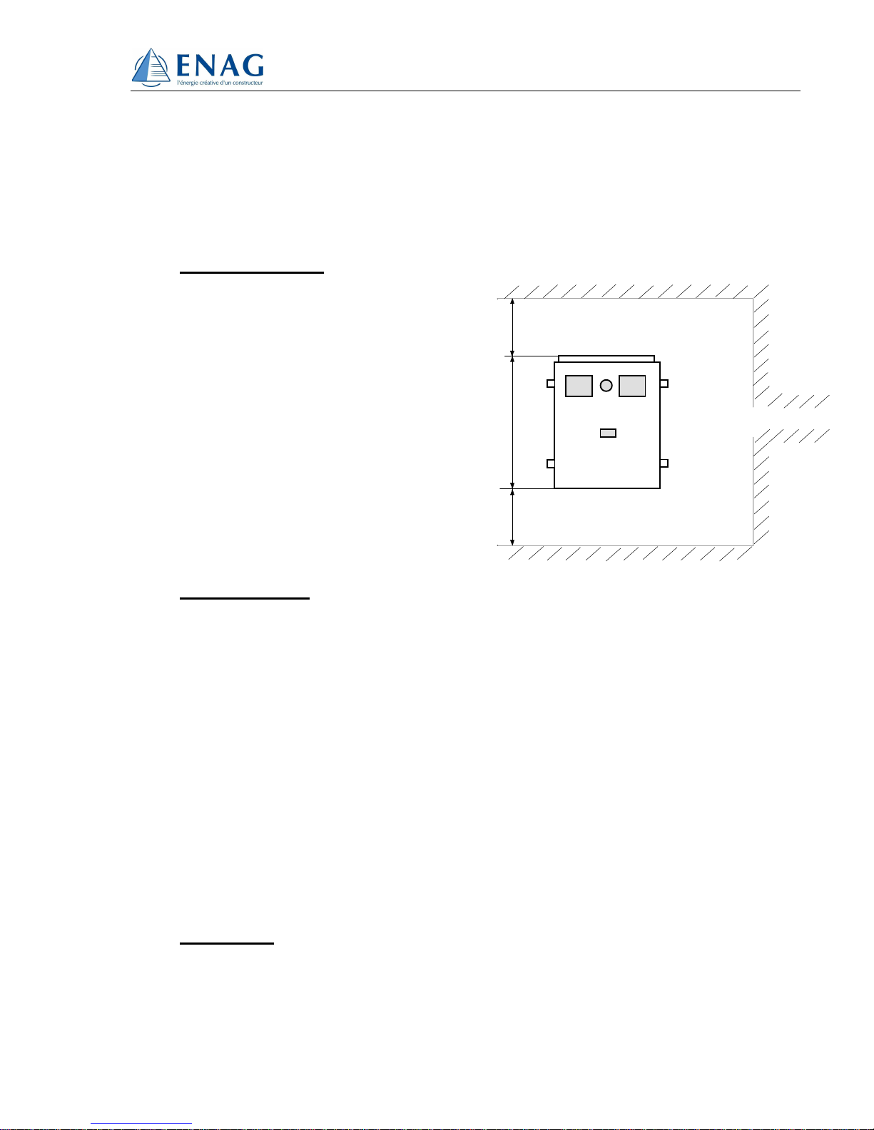
5.1 INSTALLATION
As
the appliance is cooled by natural
convection, a minimum allowance
must be left for installation as shown.
Mounting centre distance and space
requirement: see enclosed drawing.
The situation of the charger must be
adapted to its protection rating.
5.2 CONNECTION
The cable fixation is done on the connecting bar.
A shielded cable connection attenuates electromagnetic disturbance and reduces
the susceptibility of the appliance. This type of cable is recommended in all
installations.
The ground terminal or lug of the appliance must be connected by a short, wide
strap to the installation ground. See cables fixation plan.
The ground strap of the shielded cables must be linked to the appliance ground
inside the case.
Separate the supply, load and control cables.
5.3 SETTINGS
See enclosed drawing.
L=100
L=100
Ceiling
Floor

06715DAF
Page 8 / 14
5.4 TROUBLESHOOTING
5.4.1 Switch on 0
The led functioning on emergency battery remains switched off.
Check the presence of voltage at the input terminals, the state of the F5 and F6
fuses.
The voltmeter does not show the stand-by battery vol
tage.
Check the presence of voltage at the input terminals, the state of the F3 and F4
fuses.
.
5.4.1 Switch on 1
The led main source presence remains switched off.
Check the presence of voltage at the input terminals, the state of the F1 and F2
fuses.
The led main source presence is lit and the led functioning on main source remains
switched off.
IF OPTION A : priority to the stand-by source. Use of the control PCB in U4 on the
PAL REF GMDSS24A
- The led functioning on stand-by source is lit.
Check the voltage of the main source.
Check the stand-by battery test is not running.
- The led functioning on emergency source is lit.
Check the voltage of the main source and the stand-by source.
IF OPTION B : priority to the emergency source. Use of the control PCB in U4 on the
PAL REF GMDSS24B
- The led functioning on emergency source is lit.
Check the voltage of the main source.
- The led functioning on stand-by source is lit.
Check the stand-by battery test is not running.
Check the voltage of the main source and the emergency source.

06715DAF
Page 9 / 14
The led stand-by battery default is lit.
If the red led on the control PCB is lit, this means that a stand-by battery test has
been carried out and that the result is negative. This led will remain lit until the next
test.
If the red led on the control PCB is not lit, this means that an over voltage on the
stand-by battery has been detected.
In both cases, check the stand-by battery.
Contact the ENAG Technical Department who will indicate any further tests to be carried
out according to the measuring and testing means available to the operator.
In case of failure persistence, please contact the ENAG factory. The material must be
di
smounted and sent to the factory where the internal electronic circuits are checked on an
appropriate test bench.
6 - MAINTENANCE
Switch off the power.
If the appliances are situated in a dusty atmosphere, clean them periodically with a
vacuum cleaner as a build-up of dust prevents heat dissipation.
An annual check on the main nuts and screws may prove
necessary in highly
disturbed environments (strong vibrations, wide temperature variations, etc.).
A full technical inspection by a qualified inspector is recommended every year.

06715DAF
Page 10 / 14
APPENDIX
Dimensions (alimentation box) N° 06715 05
Dimensions (deported platen) N° 06715 15
Terminal N° 04933 04
Implantation N° 04933 09
Implantation cover N° 06715 10
Electrical drawing N° 06715 06
Spare parts list N° 06715 RF
Cables fixation N° 04933 11
Setting plan (control PCB) N° 04834 05
Connection N° 06715 16
Synoptic N° 04809 09
Synoptic N° 04809 10

06715DAF
Page 11 / 14
Guidelines on equipment installation
By
virtue of European directive 89/336/EC, the equipment must conform to electromagnetic
compatibility criteria Date of application: January 1st, 1996.
The
two main demands in terms of electromagnetic compatibility are:
Emission: Protection of the environment against disturbance by conduction and radiation.
Immunity: Absence of susceptibility in a disturbing atmosphere.
Installation
General Rules
The equipment must be installed according to the recommendations of the user manual. The
main rules are as follows:
Use shielded cables with a correct section in order to power the appliance and the
load centres within acceptable tolerance limits.
(Definition criteria: nature and length of the cables, ambient temperature, voltage
drop, type of tracking, etc.).
Make sure the equipment is correctly ventilated for good heat dissipation
(installation space, ambient temperature, etc.).
Choose the location in accordance with the protection rating of the appliance.

06715DAF
Page 12 / 14
Emc-related installation guidelines
Cables:
Use shielded cable for all connections (*). The shielding must be grounded on the
transmitter side and the receiver side.
Keep the cables and shielding connections as short as possible.
Feed the cables as close as possible to the ground (“loose” cables or loops are to be
avoided - fasten the cables down to the ground).
Separate the supply and load cables.
Separate the power and control cables (minimum 200 mm).
The cables should only supply power to the appliance. A branch connection or bridge to
supply another appliance are to be prohibited.
(*) This is a recommendation but is not compulsory. The installation electrician will consider
the EMC environment and decide whether or not to use shielded cable.
Metal casing
The cases or cabinets for the appliances or containing the equipment must be metallic or
have a conductive coating.
The ground bolt or lug of the casing should be connected to the main ground by the
shortest strap possible. The bolt connected to the main ground must have a good electrical
contact (scratch off the paint and weld the bolt).
The ground being the reference point of the potential, the various current-bearing parts of
the equipment environment must be made equipotential by linking them together (where
possible, metal shielding and troughs are grounded with the shortest straps).

06715DAF
Page 13 / 14
Additional attenuator systems
The coils of contactors, relays, solenoid valves and electromagnets must be
equipped with overvoltage arresters (RC circuits, varistor or diode on direct current,
RC circuits or varistor on alternating current).
Additional filters may be mounted according to applicable standards. Disturbance
a
ttenuation enables the specified levels to be attained. The filters must be mounted
as near as possible to the appliance.
Remember that filters increase the leakage current.
As a general rule, we recommend consulting the manufacturer before installing a
filter, particularly on the load and control cable side.


SEEL006715D N° 06715RAD PAGE 1 / 1
Ind :
Designation :
DATE : NATO CODE :
D
ICA - GMDSS 30 - RAE (Deported platen A + V)
23/09/2016 F3645
Nb Rep Designation Partnumber Manufacturer Item code
2 F17-F18 Fuse 10Agg 10x38 13310 LEGRAND 30001307
PL2 POWER CARD
8 F1 à F8 Fuse ATO 15A-32V 257015 LITTELFUSE 30011476
6 F9 - F14 Fuse ATO 7,5A-32V 25707,5 LITTELFUSE 30013145
2 F15-F16 Fuse 5x20 D1-0,31A CEHESS 30005209
PL1 CHARGER CARD
2 F1 Fuse 6,3x32 15A 250V ( POWER SUPPLY 230VAC ) 326015 LITTELFUSE 30013200
SPARE PARTS LIST


 Loading...