

Page 1
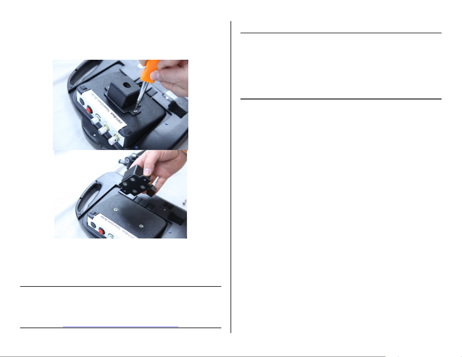
5. Removing the mounting socket for table top use:
You can remove the mounting socket from the Communication Builder by removing
the two Phillips Head screw on the socket itself. (See Fig. 4).
Care of Unit:
The Mounting System can be wiped clean with any mild household multi-purpose
cleaner and disinfectant. Do not use abrasive cleaners, as they will scratch the
surface of the unit.
Mountable 7 Level Communication Builder
#7075M
7 Level Communication Builder with Mounting
Arm #7075X
MOUNTING USER’S GUIDE
Page 2
Now mountable!
Our bestselling 7-Level Communicator now comes on a mounting system that is
easy to attach to any wheelchair, tabletop, bedrail or tray. The #7075X version
includes the communicator, mounting base, and our Light Duty Magic Arm. The
#7075M version includes the communicator and mounting base only but can be used
with our #1557 or #1631 Mounting Systems. Also, the mounting base is removable if
tabletop or tray use is desired. See #7075 at right for a complete description of the
features of this communicator. Size: 12 ½ "L x 9 ¼ "W x 4"H. Requires 4 AA
Batteries.
1. Mounting Arm Assembly: Your mounting system consists of three main parts,
an adjustable arm, Communication Builder mounting socket and a clamp. First
you will need to assemble the 3 main parts. To attach the clamp to the arm,
loosen the set screw on the clamp (see Fig. 1). Next depress the Silver Spring
loaded locking pin, then push one of the ends of the mounting arm into the
clamp(see Fig. 2) Please Note: you need to line up the flat part of the Mounting
Arm end post with the set screw in the clamp. This will prevent the arm from
spinning freely inside the clamp. Once this is done you can tighten the setscrew
to lock the Mounting arm to the clamp.
Tighten
Clamp
Locking
Knob
Fig. 1
2. Clamping Options: Our mounting clamp is designed for mounting to tubular
(wheelchair, bedrail, walker, etc.) or flat surfaces such as a table top or desk. For
flat surface mounting use the included wedge insert shoe stored in front of the
locking knob on the clamp (see Fig.2) Loosen locking knob slightly to remove
wedge, tighten knob once wedge has been removed.
Caution:
Do not over tighten the adjusting knobs, or try to move or adjust the mounting
system after you have tightened the adjusting knobs. Doing so can damage the
Mounting System and void your warranty.
Fig.2
3. At this point we recommend you place your mounting arm without the
Communication Builder and do a rough setup, you can fine tune your
adjustments after you have placed the Communication Builder on the arm. Do
not force or try adjusting the arm without first loosening the set knobs for that
portion of the arm. Each section of the arm has a set knob. Once you have the
arm in the desired position you can tighten the knobs to lock the arm in place.
4. Once the arm is in position you can now place your Communication Builder on
the arm. First back off the set knob on the Communication Builder until it is
flush with the inside of the opening. This is necessary to allow the holder to be
pushed all the way down on the mounting arm post. The post at the end of the
arm also has a flat spot, which needs to be lined up with the set screw on the
Communication Builder’s mounting socket. Once this is done you can tighten
the set knob to lock the Communication Builder to the arm. Please Note: Make
sure to back the set screw enough to allow the mounting socket to be pushed all
the way down on the post of the arm, failure to do so will cause the
Communication Builder to fall off the mounting arm and a fall could cause
damage to your Communication Builder. (See Fig. 3).
Tighten Set
Knob
Fig. 3
Rev 12/8/11
 Loading...