

Page 1

All Rights Reserved 1997 - 2015 ENABLE-IT- Proprietary and Confidential
Page1of
119
Enable-IT 8950
Gigabit Ethernet
DSLAM
User Manual
Page 2

All Rights Reserved 1997 - 2015 Enable-IT, Inc. Page 2 of 119
Copyright © 1997-2015 Enable-IT, Inc. All rights reserved. No part of this
documentation may be reproduced in any form or by any means or used to make
any derivative work (such as translation, transformation, or adaptation) without
written permission from Enable-IT, Inc.
Enable-IT, Inc. reserves the right to revise this documentation and to make
changes in content from time to time without obligation on the part of Enable-IT,
Inc. to provide notification of such revision or change.
Enable-IT, Inc. provides this documentation without warranty, term, or condition of
any kind, either implied or expressed, including, but not limited to, the implied
warranties, terms or conditions of merchantability, satisfactory quality, and fitness
for a particular purpose. Enable-IT, Inc. may make improvements or changes in
the product(s) and/or the program(s) described in this documentation at any time.
If there is any software on removable media described in this documentation, it is
furnished under a license agreement included with the product as a separate
document, in the hard copy documentation. If you are unable to locate a copy,
please contact Enable-IT, Inc. and a copy will be provided to you.
UNITED STATES GOVERNMENT LEGEND
If you are a United States government agency, then this documentation and the
software described herein are provided to you subject to the following:
All technical data and computer software are commercial in nature and developed
solely at private expense. Software is delivered as "Commercial Computer
Software" as defined in DFARS 252.227-7014 (June 1995) or as a "commercial
item" as defined in FAR 2.101 (a) and as such is provided with only such rights as
are provided in Enable-IT, Inc.'s standard commercial license for the Software.
Technical data is provided with limited rights only as provided in DFAR
252.227-7015 (Nov 1995) or FAR 52.227-14 (June 1987), whichever is applicable.
You agree not to remove or deface any portion of any legend provided on any
licensed program or documentation contained in, or delivered to you in
conjunction with, this User Guide.
Page 3

All Rights Reserved 1997 - 2015 Enable-IT, Inc. Page 3 of 119
Tables of Contents
TABLES OF CONTENTS...........................................................................................................................................3
CHAPTER 1 INTRODUCTION.................................................................................................................................. 5
1.1 FEATURES........................................................................................................................................................... 6
1.2 SPECIFICATION....................................................................................................................................................7
CHAPTER 2 HARDWARE INSTALLATION.......................................................................................................... 8
2.1 FRONT PANEL..................................................................................................................................................... 8
2.1.1 Connectors................................................................................................................................................ 8
2.1.2 LED Indicators...........................................................................................................................................9
2.1.3 Reset Button..............................................................................................................................................9
CHAPTER 3 WEB CONFIGURATION.................................................................................................................. 10
3.1 ADMINISTRATION...............................................................................................................................................14
3.1.1 IP Address............................................................................................................................................... 15
3.1.2 Switch Setting......................................................................................................................................... 16
3.1.3 Console Port Information...................................................................................................................... 19
3.1.4 Port Configuration.................................................................................................................................. 19
3.1.5 SNMP Configuration.............................................................................................................................. 23
3.1.6 Syslog Setting......................................................................................................................................... 29
3.1.7 Alarm Configuration............................................................................................................................... 29
3.1.8 Temperatures & Fan Setting................................................................................................................ 30
3.1.9 Firmware Update.................................................................................................................................... 30
3.1.10 Configuration Backup.......................................................................................................................... 31
3.1.11 SNTP Setting........................................................................................................................................ 32
3.2 L2 FEATURES....................................................................................................................................................33
3.2.1 VLAN Configuration............................................................................................................................... 33
3.2.1.1 Static VLAN........................................................................................................................................................ 34
3.2.1.2 GVRP VLAN.......................................................................................................................................................38
3.2.1.3 QinQ VLAN.........................................................................................................................................................40
3.2.2 Trunking................................................................................................................................................... 42
3.2.3 Forwarding & Filtering........................................................................................................................... 45
3.2.4 IGMP Snooping...................................................................................................................................... 48
3.2.5 Spanning Tree........................................................................................................................................ 49
3.2.5.1 System Configuration....................................................................................................................................... 50
3.2.5.2 PerPort Configuration....................................................................................................................................... 51
3.2.5.3 Instance.............................................................................................................................................................. 52
Page 4

All Rights Reserved 1997 - 2015 Enable-IT, Inc. Page 4 of 119
3.2.5.4 Interface.............................................................................................................................................................. 52
3.2.6 DHCP Relay & Opt.82........................................................................................................................... 53
3.2.6.1 DHCP Option 82................................................................................................................................................54
3.2.6.2 DHCP Relay.......................................................................................................................................................54
3.2.6.3 DHCP Option 82 Router Port.......................................................................................................................... 54
3.2.6.4 DHCP Opt. 82 Port Table................................................................................................................................ 55
3.3 ACL...................................................................................................................................................................56
3.3.1 IPv4...........................................................................................................................................................57
3.3.2 Non-IPv4.................................................................................................................................................. 58
3.3.3 Binding..................................................................................................................................................... 58
3.4 SECURITY.......................................................................................................................................................... 60
3.4.1 Security Manager................................................................................................................................... 60
3.4.2 MAC Limit................................................................................................................................................ 61
3.4.3 802.1x Configuration..............................................................................................................................62
3.5 QOS.................................................................................................................................................................. 65
3.5.1 QoS Configuration..................................................................................................................................65
3.5.2 ToS/DSCP............................................................................................................................................... 67
3.6 MONITORING..................................................................................................................................................... 68
3.6.1 Port Status...............................................................................................................................................68
3.6.2 Port Statistics.......................................................................................................................................... 69
3.7 VDSL................................................................................................................................................................ 70
3.7.1 Configuration........................................................................................................................................... 70
3.7.2 Profile Table............................................................................................................................................ 72
3.8 RESET SYSTEM.................................................................................................................................................73
3.9 REBOOT.............................................................................................................................................................73
CHAPTER 4 CONFIGURATION VIA CONSOLE................................................................................................ 74
4.1 LOGIN INTO THE CONSOLE...............................................................................................................................75
4.2 GENERAL INFORMATION OF COMMANDS......................................................................................................... 76
4.3 CONFIGURATION............................................................................................................................................... 77
4.4 COMMAND DESCRIPTIONS................................................................................................................................79
4.4.1 System Commands................................................................................................................................79
4.4.2 Switch Static Configuration................................................................................................................... 79
4.4.3 Trunk Commands...................................................................................................................................82
4.4.4 LACP Commands...................................................................................................................................83
4.4.5 VLAN Mode & Commands....................................................................................................................84
4.4.6 GVRP Commands..................................................................................................................................86
4.4.7 QinQ Commands....................................................................................................................................88
4.4.8 Misc Configuration................................................................................................................................. 89
4.4.9 Administration......................................................................................................................................... 90
Page 5

All Rights Reserved 1997 - 2015 Enable-IT, Inc. Page 5 of 119
4.4.10 Port Mirroring........................................................................................................................................ 91
4.4.11 QoS.........................................................................................................................................................92
4.4.12 Commands for MAC............................................................................................................................ 93
4.4.13 MAC Limits............................................................................................................................................ 94
4.4.14 Protocol Related Commands............................................................................................................. 95
4.4.15 SNMP...................................................................................................................................................101
4.4.16 IGMP.................................................................................................................................................... 105
4.4.17 802.1x.................................................................................................................................................. 106
4.4.18 DHCP Relay & Option 82................................................................................................................. 108
4.4.19 Syslog.................................................................................................................................................. 109
4.4.20 SSH...................................................................................................................................................... 109
4.4.21 Reboot switch..................................................................................................................................... 109
4.4.22 TFTP Function....................................................................................................................................110
4.4.23 Access Control List............................................................................................................................ 111
4.4.24 SIP/SMAC Binding.............................................................................................................................114
Chapter 1 Introduction
Enable-IT 8950 Gigabit 8 Port IP DSLAM presents the ideal and efficient solution for
Telecom, ISP (Internet Service Provider), or SI (System Integration) with 8-port VDSL2
and 2-port gigabit Ethernet combo interfaces (TP and SFP) in the 1U height design.
The IP DSLAM offers the benefits of high speed connectivity with an efficient
management system, robust layer 2 features with advanced security system, and
reliable hardware design with monitoring system.
Package Contents:
(1) Enable-IT 8950 Gigabit PoE 8 Port VDSL2 IP DSLAM
(1) Enable-IT 8950 Gigabit PoE Ethernet DSLAM User Manual
(1) Country Specific Power Cord
(1) Set of Rubber Feet for easy placement
(1) Serial to Ethernet Console Cable (DB9-RJ45)
(1) Set of 19” Rack Mount Brackets and Screws
(x) Custom RJ-11 to RJ-45 Patch cord - for OOTBT (Out of the Box Test)
Page 6

All Rights Reserved 1997 - 2015 Enable-IT, Inc. Page 6 of 119
1.1 Features
1U Compact Design with 8 PoE enabled Extended Ethernet Ports.
Supports VDSL2 Profiles 8a/8b/8c/8d/12a/12b/17a/30a.
Supports Powerful Traffic Classification Tools, such as QoS, ToS and DSCP.
Supports L2/L3 Content Filtering.
Supports Port-Based VLAN, Protocol-Based VLAN and VLAN Mapping.
Supports L2 Bridge Functions (IEEE 802.1d) and Multicast.
DHCP Server/Relay/Client
DNS Proxy
Flexible Deployment and Maintenance.
Web-based management with a user friendly interface.
Configuration backup and restoration.
Page 7

All Rights Reserved 1997 - 2015 Enable-IT, Inc. Page 7 of 119
1.2 Specification
Hardware Interfaces:
RJ-45 x 8 VDSL2 Ports
2 x Secure locking PoE input ports
2 x Gigabit Ethernet Combo ports
(100/1000 Based-T and SFP)
1 x RJ-45 Console Port
1 x RJ-45 Alarm Port for 4 Alarm
Inputs
LED Indicators:
System: PWR
Gigabit Port: LINK/ACT, SPEED
1000/100
Alarm: RUN/ALARM
VDSL: VDSL Link/Sync
Standards Support:
VDSL2 ITU-T G.993.2
VDSL2 Profiles: 8a, 8b, 8c, 8d, 12a,
12b, 17a and 30a
802.1d L2 Bridging
DHCP Server/Client/Relay
IEEE 802.1q VLAN (Port-based
VLAN and Protocol-Based VLAN)
VLAN Stacking (Q-in-Q)
IEEE 802.1d Spanning Tree Protocol
(STP)
IEEE 802.3ad Link Aggregation
Protocol Support:
IGMP Snooping/Proxy v1, v2 and v3
Multicast Forwarding with IGMP
Snooping v1 and v2 (RFC 1112 and
RFC 2236)
Multicast MAC address mapping
Up to 512 Multicast Channels
Profile-based Multicast Access
Control
(up to 24 profiles)
Fast and Normal Leave Modes
Security:
L2 Frame Filtering by MAC
Addresses
L3 Frame Filtering by IP Addresses,
protocol ID, and TCP/UDP
DHCP and ARP Broadcasting
Frames Filtering
Support Secured Forwarding
Management:
Local Management: RS-232 and
Telnet CLI, Web/SNMP
management.
Remote in-band Management:
Web/SNMP/Telnet
Support SNMP v1/v2/v3
Operating Environment
Operating Temperature: 14°F to
122°F (-10°C to 50°C)
Storage Temperature: -40°F to 158°F
(-40°C to 70°C)
Humidity: 10% - 95%
(non-condensing)
Physical/Electrical
Dimensions: 404 x 174 x 44.5 mm,
1U height
Power: 100-240 V ac, 50-60 Hz
Power Consumption: 30Watts
maximum
Regulatory Compliance
CE
VCCI
EN60950
Page 8
All Rights Reserved 1997 - 2015 Enable-IT, Inc. Page 8 of 119
Chapter 2 Hardware Installation
This chapter shows the front panel and how to install the hardware.
2.1Front Panel
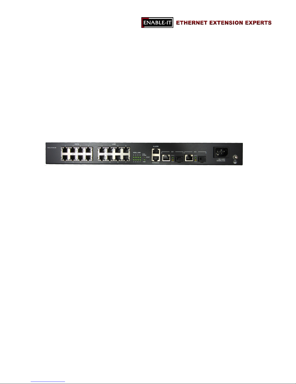
8950 Gigabit 8 Port IP DSLAM includes all connectors and LED indicators on its front
panel so only a few installations are required in order to build the network solution.
2.1.1 Connectors
LINE
LINE is for connecting 8 VDSL2 ports with a Customer RJ-11 to RJ-45 test cable
and then your RJ-11 to wiring.
ALARM
For alarm inputs and outputs.
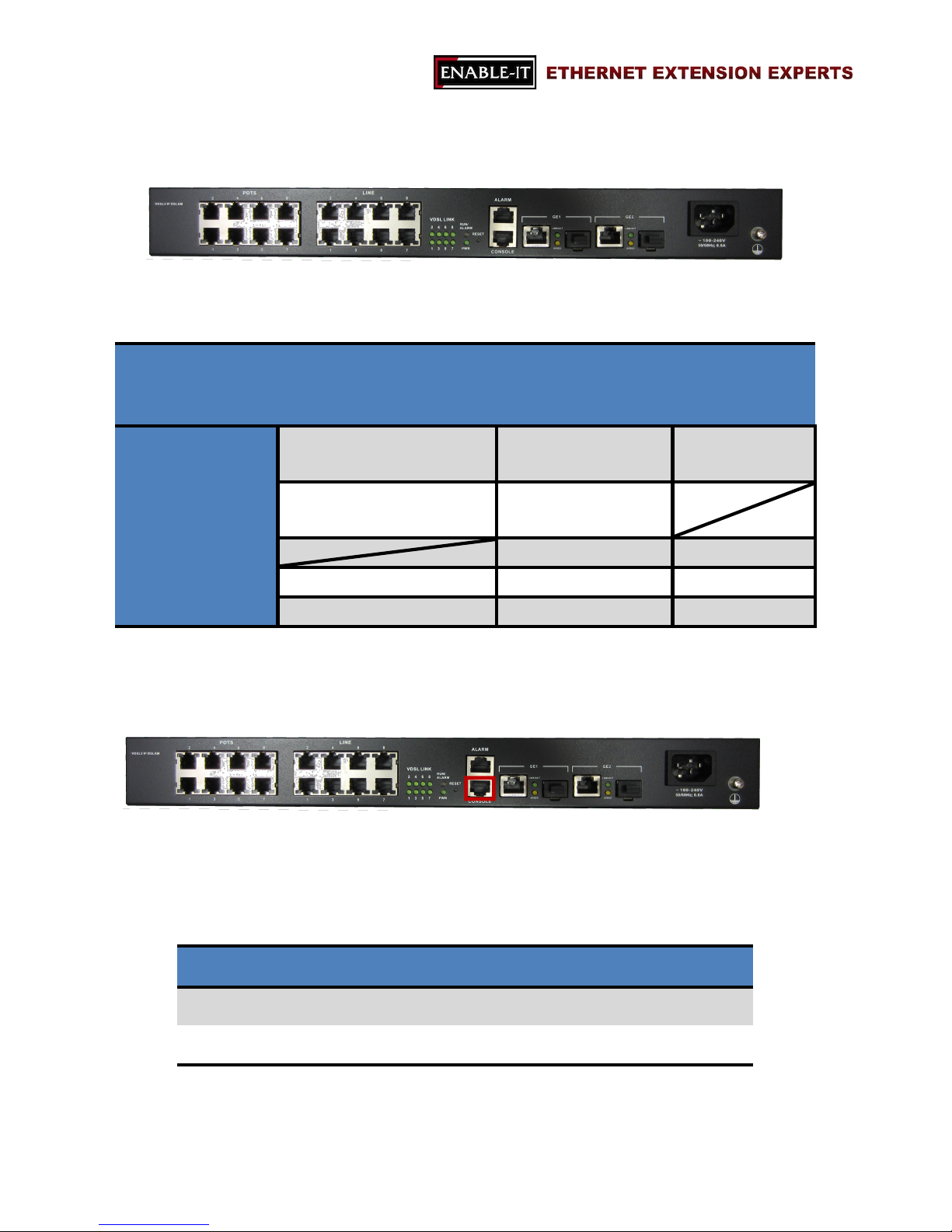
CONSOLE
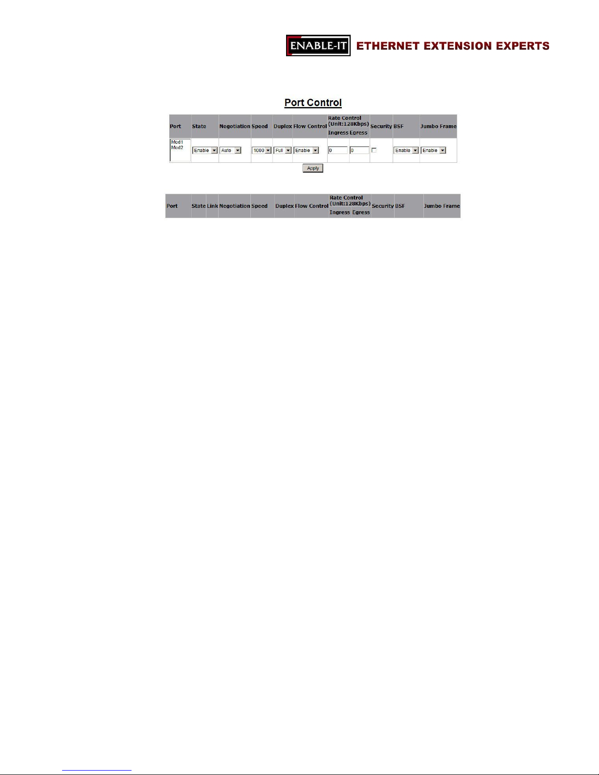
Users are able to access 8950 Gigabit 8 Port IP DSLAM locally with CONSOLE port.
Via CONSOLE, users are able to configure 8950 Gigabit 8 Port IP DSLAM with
menu-driven interface with any terminal emulation program, such as, Hyperterminal
and Teraterm. (115200, 8, None, 1, None)
GE1 & GE2
For connecting Gigabit Ethernet, 8950 Gigabit 8 Port IP DSLAM provides Gigabit
Ethernet combo interfaces, TP and SPF.
TP: 10/100/1000 BaseT copper (RJ-45 connector).
SFP: 1000 Base-SX/LX mini-GBIC slot.
POWER
The connector is for 100V ~ 240V AC power inputs (50Hz~60Hz, 1.5A).
Page 9
All Rights Reserved 1997 - 2015 Enable-IT, Inc. Page 9 of 119
2.1.2 LED Indicators
Blinking
On
Off
VDSL LINK (1 ~ 8) VDSL2 link is active
(transmitting data or training)
VDSL2 link is ready VDSL2 link is down
RUN/ALARM System Boot-up Green:Alarm is detected
Red: Alarm
PWR Power On Power Off
GE1/GE2 LINK/ACT Transmitting Data 1000Mbps Link Down
SPEED Transmitting Data 10/100Mbps Link Down
2.1.3 Reset Button
The reset buttons allows users to reboot the 8950 Gigabit 8 Port IP DSLAM or load the
default settings.
Press the reset button for Action
1 ~ 5 seconds Reboot the IP DSLAM
Over 5 seconds Load the default settings
Page 10
All Rights Reserved 1997 - 2015 Enable-IT, Inc. Page 10 of 119
Chapter 3 Web Configuration
The 8950 Gigabit IP DSLAM allows users to manage and change its configurations with
web browsers. Users are able to login the web management system with any standard
web browser, such as, Internet Explorer, Firefox, etc.
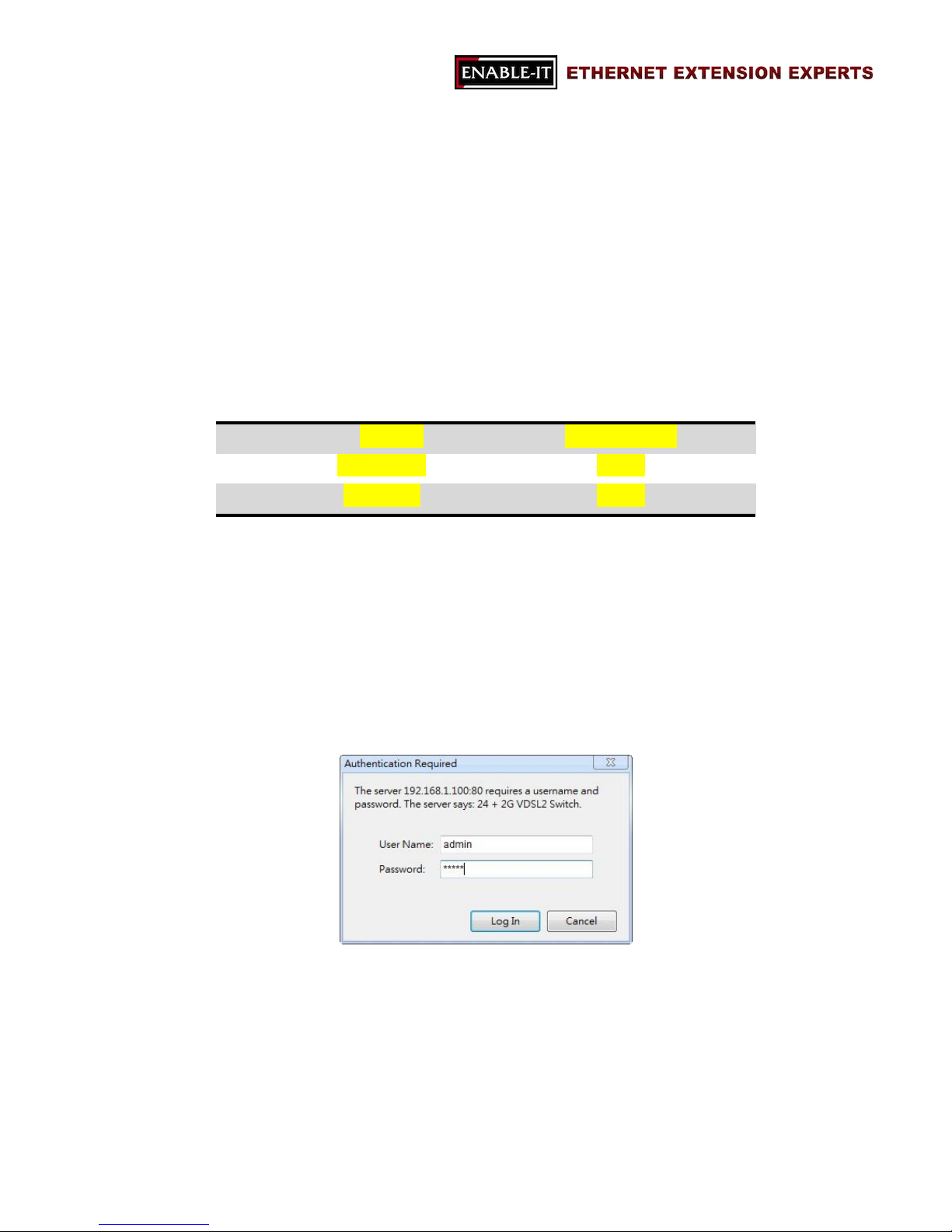
Default IP Address 192.168.0.100
Default User Name admin
Default Password admin
TABLE 1 DEFAULT LOGIN INFORMATION
Note: Please make sure the IP address is correct once the IP of the management web
site is changed.
Once users are able to login the web management page successfully, the login message
box will pop up as the following image.
Page 11
All Rights Reserved 1997 - 2015 Enable-IT, Inc. Page 11 of 119
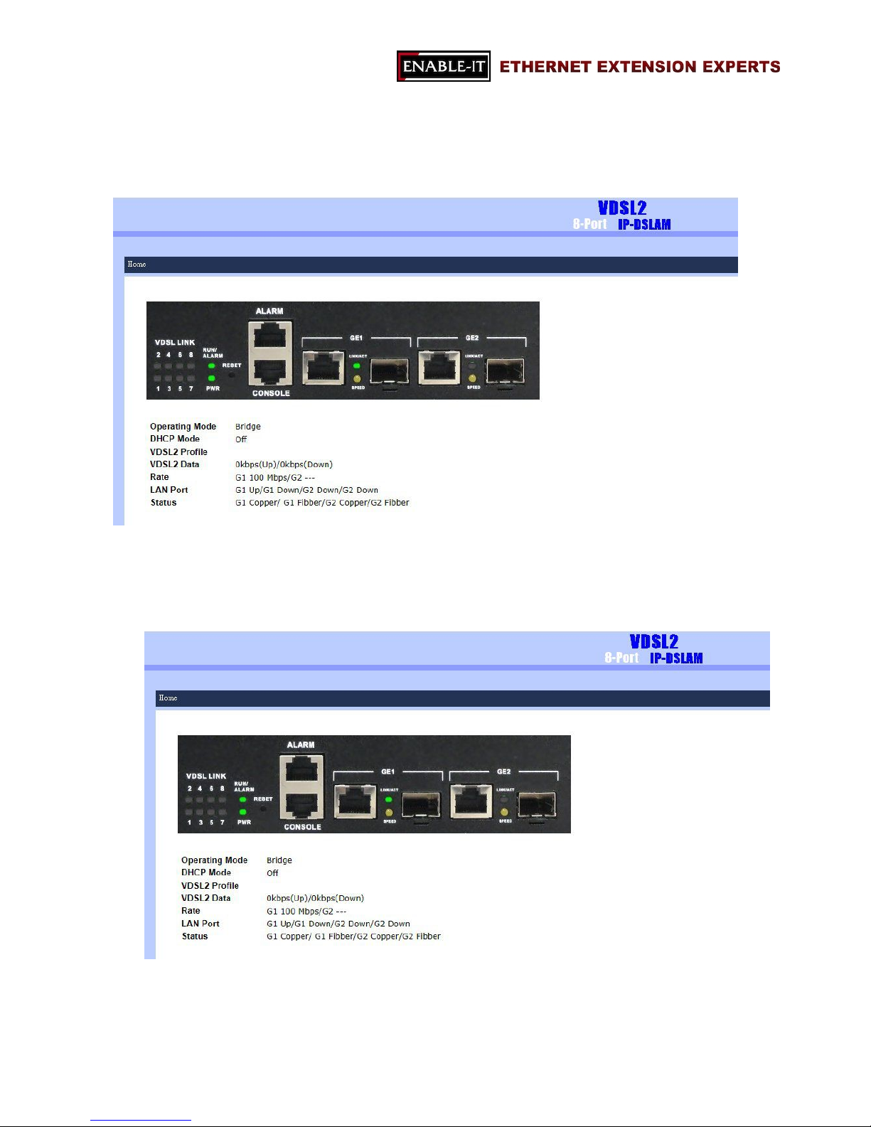
Please key in the correct login information and the main page of the management will be
showed as the following image.
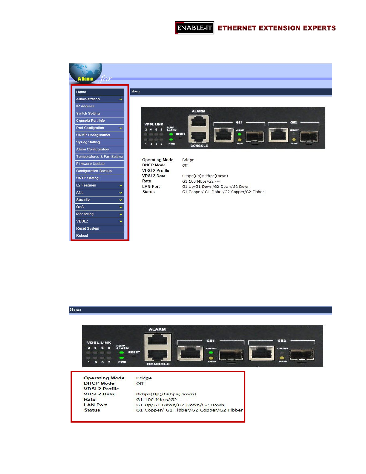
HOME page of the management system includes three major sections.
1. Title section
This section indicates the model name of the device.
Page 12
All Rights Reserved 1997 - 2015 Enable-IT, Inc. Page 12 of 119
2. Menu section
“Menu” section is located on the left hand side of the page and users are allowed to
change the configuration and review the status of the device by interacting this
section.
3. Information section
Page 13

All Rights Reserved 1997 - 2015 Enable-IT, Inc. Page 13 of 119
“Information” section presents the real-time LED status and the current status of the
8950 Gigabit IP DSLAM.
Note: users are able to go back HOME page anytime by clicking on “Home” on the menu
section.
The following sections will introduce users the features of the 8950 Gigabit IP DSLAM.
Administration (3.1)
L2 Features (3.2)
ACL (3.3)
Security (3.4)
QoS (3.5)
Monitoring (3.6)
VDSL (3.7)
Reset System 3.8)
Reboot (3.9)
Page 14
All Rights Reserved 1997 - 2015 Enable-IT, Inc. Page 14 of 119
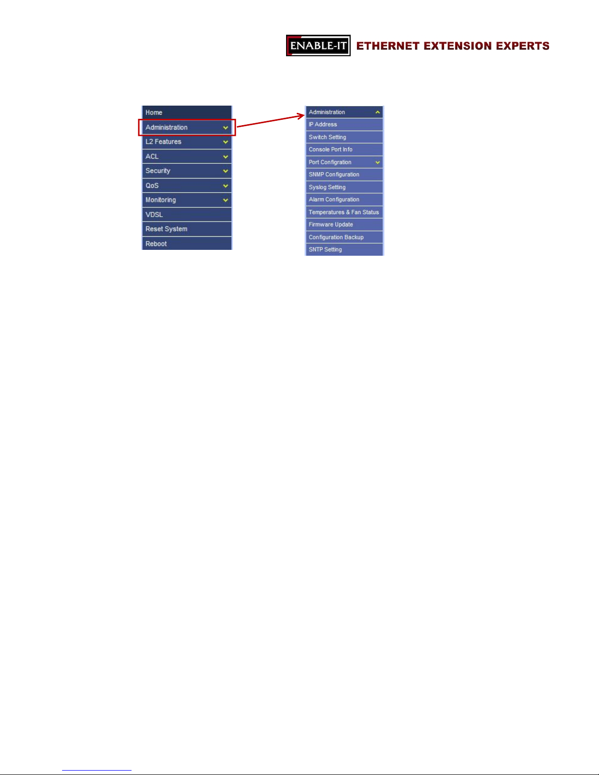
3.1 Administration
“Administration” section is for users to manage the 8950 Gigabit IP DSLAM, including the
IP address, switch settings, etc. It includes the following detail functions.
IP Address
Switch Setting
Console Port Info
Port Configuration
SNMP Configuration
Syslog Setting
Alarm Configuration
Temperatures & Fan Status
Firmware Update
Configuration Backup
SNTP Setting
Page 15
All Rights Reserved 1997 - 2015 Enable-IT, Inc. Page 15 of 119
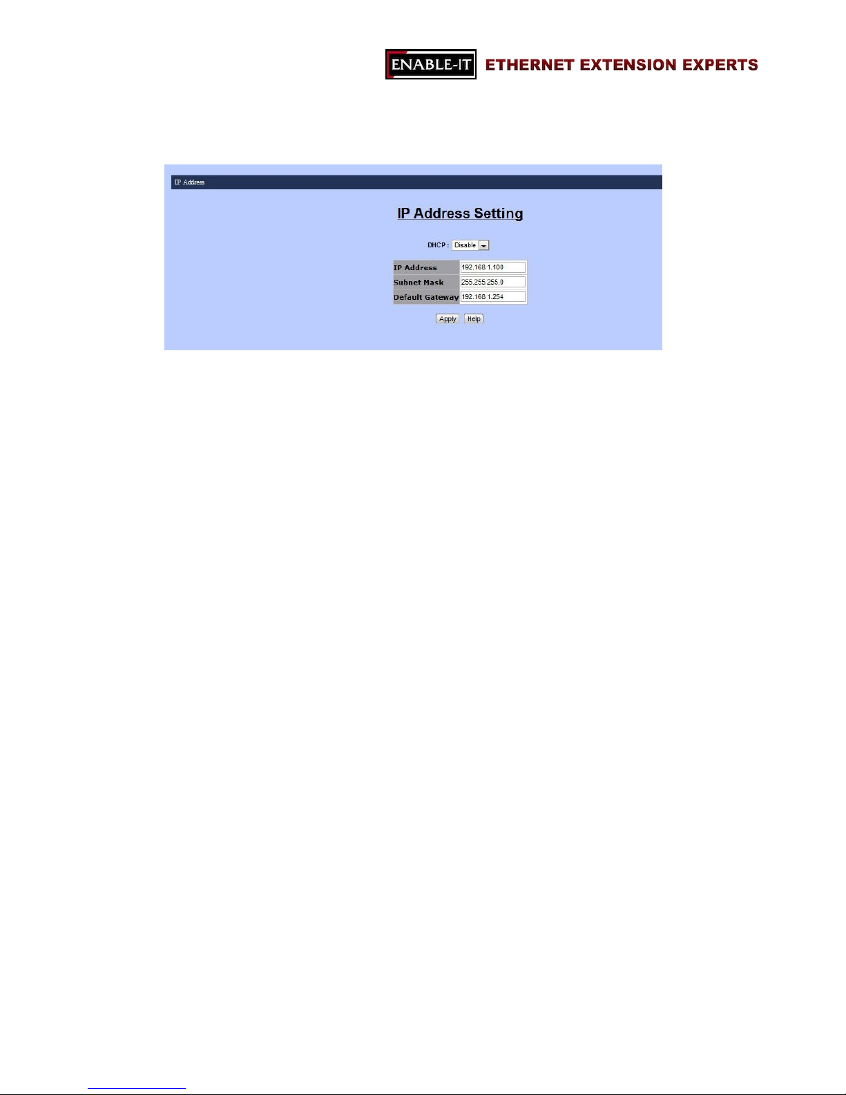
3.1.1 IP Address
“IP Address” function includes four information and users are allowed to change these
information:
DHCP mode
- Disable or enable DHCP mode
- The value of this mode will decide whether the IP address is a static IP
address or a dynamic IP address.
IP address
Subnet mask
Default gateway
Page 16
All Rights Reserved 1997 - 2015 Enable-IT, Inc. Page 16 of 119
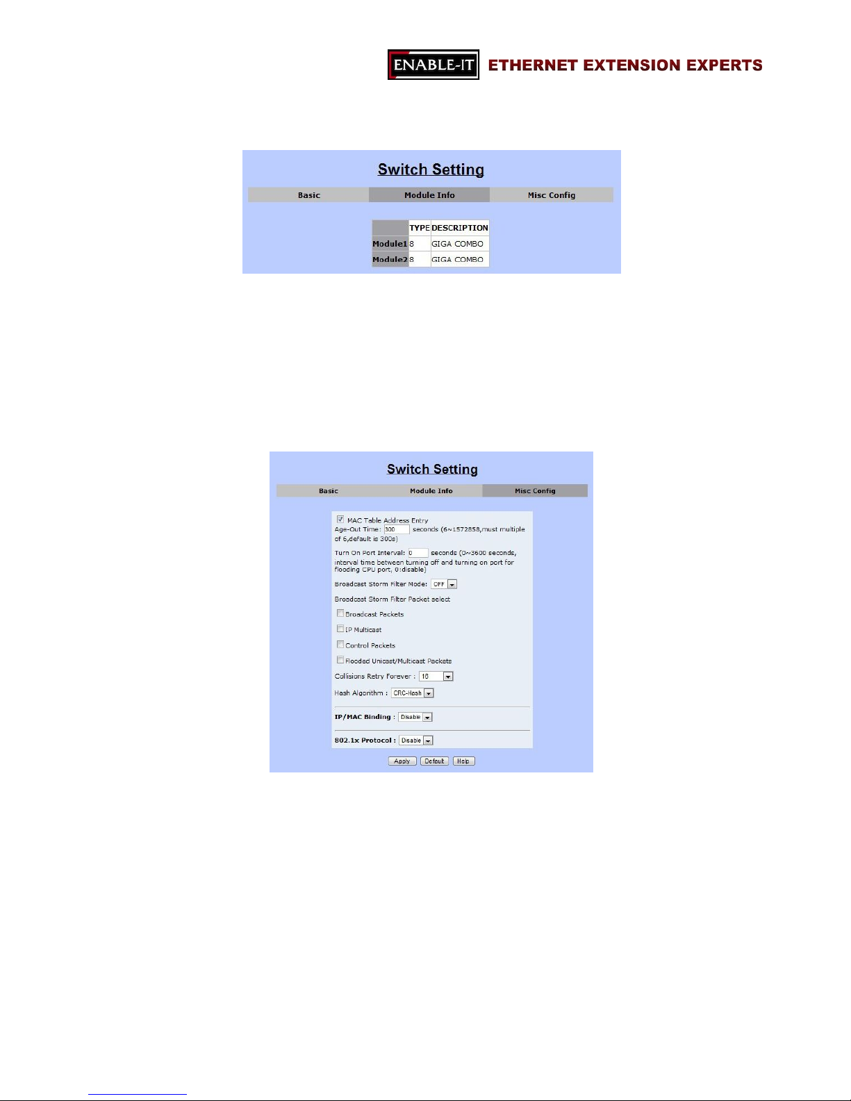
3.1.2 Switch Setting
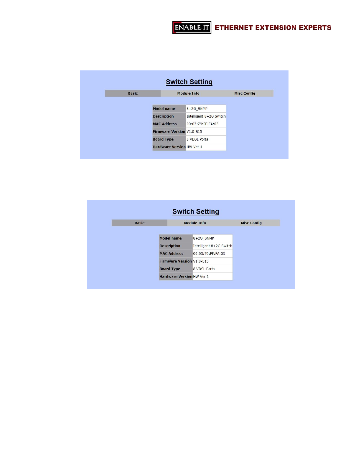
“Switch Setting” presents information of the switch in the following sub-functions. Note:
only “Misc Config” section allows users to change the settings of the switch.
Basic
In “Basic” tab, the basic information of the 8950 Gigabit IP DSLAM is presented.
- Model name
- Description
- MAC address
- Firmware version
- Board type
- Hardware version
Page 17
All Rights Reserved 1997 - 2015 Enable-IT, Inc. Page 17 of 119
Module Info
This section shows the information of uplinks, Gigabit Ethernet 1 and Gigabit
Ethernet 2.
Note: in the following contents, these two uplinks will be called Mod1 and Mod2.
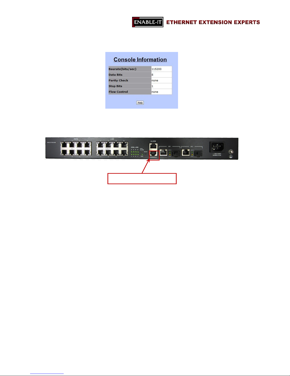
Misc Config
Users are allowed to modify the following details of the switch.
- MAC address age-out time
This value is for setting up how many seconds that an inactive MAC
address remains.
- Turn on port interval
This value for setting up the time interval that the CPU port should be
enabled after flooding attacks. Note: 0 means never enable the CPU port.
- Broadcast storm filter mode
This feature is to set up the threshold value of broadcast traffic for ports.
Options: off, 1/2, 1/4, 1/8 or 1/16 (Note: the value is the percentage of the
Page 18

All Rights Reserved 1997 - 2015 Enable-IT, Inc. Page 18 of 119
port’s ingress bandwidth used by broadcast traffic.
- Broadcast storm filter packets select
This option allows users to choose the type of the target packet for
broadcast storm filter mode.
If there is no type is chosen, this means broadcast storm filter mode is
off.
Options: broadcast packets, IP multicast, control packets, and flooded
unicast/multicast packets.
- Collisions retry forever
This function will allow users to choose how many times the IP
DSLAM should retry when a packet meets a collision.
Disable, 16, 32 or 48 collision number
Note: when the function is disabled, this means the IP DSLAM will
retry for 6 times before packets are dropped. Otherwise, it will retry
continuously until the packet is sent successfully.
- Hash algorithm
This option is for choosing a hash algorithm for MAC address table.
CRC-Hash or DirectMap.
- IP/MAC binding
This feature allows user to enable or disable IP/MAC binding function.
Enable or disable.
- 802.1x protocol
802.1x protocol is able to enable or disable via this option.
Enable or Disable.
Users are able to save the modified settings by clicking on “Apply” button.
“Default” button is for restore the default settings; and “Help” button will provide
some information about the features with another window.
Page 19
All Rights Reserved 1997 - 2015 Enable-IT, Inc. Page 19 of 119
3.1.3 Console Port Information
The section is for users to review the settings of console port, which lets users to connect
and manage the 8950 Gigabit IP DSLAM in Command Line Interface (CLI) mode.
3.1.4 Port Configuration
“Port Configuration” section includes four detail functions of VDSL2 ports and Gigabit
Ethernet ports:
i. Port Controls
ii. Port Sniffer
iii. Protected Port
iv. VDSL Port Status
Connect to PC or Laptop
Page 20
All Rights Reserved 1997 - 2015 Enable-IT, Inc. Page 20 of 119
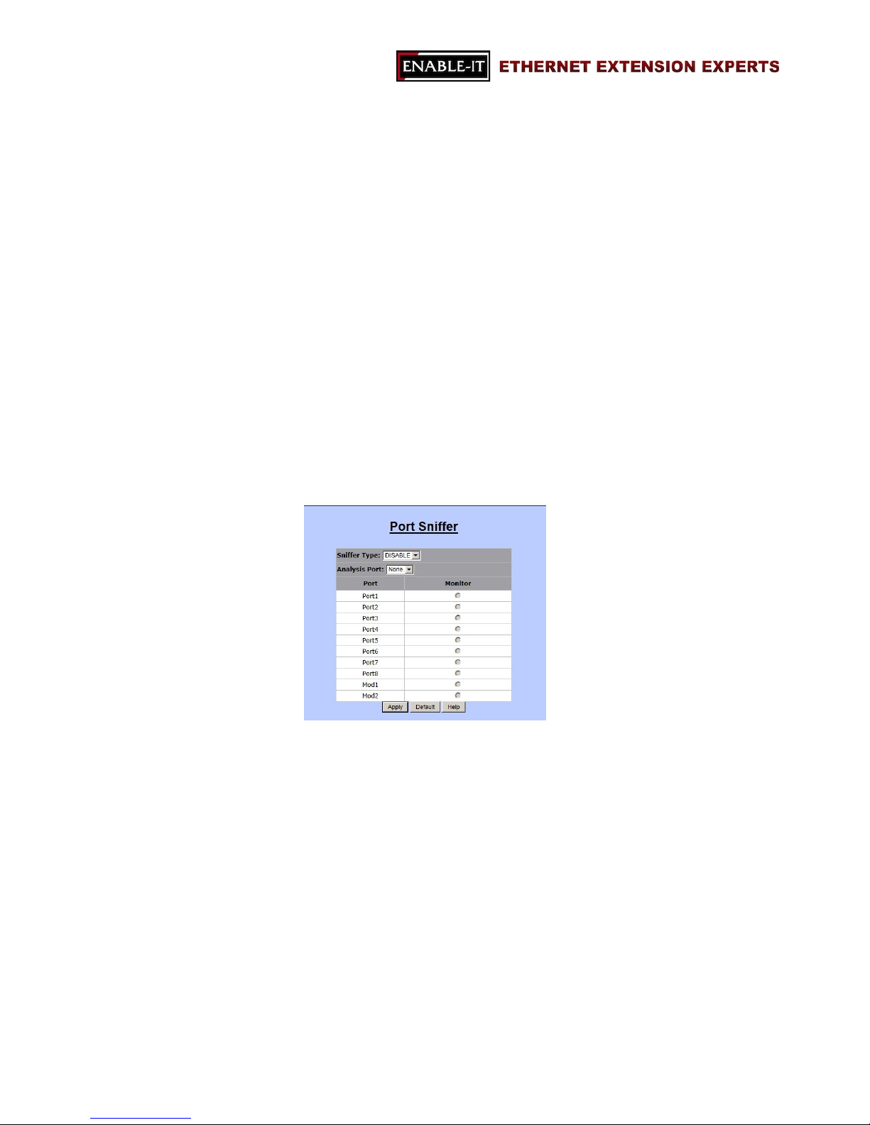
Port Controls
“Port Control” is for users to setting up the details of Gigabit Ethernet ports and
trunking ports if there exists any trunking ports. Users are allowed to configure the
following parameters.
- State
This option will enable or disable the selected port.
Enable or Disable
Note: “Disable” means to turn off the selected port; and this means there
will be no traffic going through this port.
- Negotiation
Users are able to decide whether Gigabit Ethernet ports should be
auto-negotiable or not.
Options: auto or force
Note: If “force” mode is selected, users have to provide the information of
“Speed” and “Duplex”.
- Speed
Users can setup the speed of Gigabit Ethernet ports in this function.
10, 100 or 1000
- Duplex
Half or Full
- Flow Control
Options: enable or disable
Enable: send a PAUSE signal to the sender and halts the traffic for a period
of time.
Disable: drop the exceed packets when there are too much packets to
process.
- Rate Control
Users are able to set up the specific rate for both ingress and egress ports.
Therefore, the 8950 Gigabit IP DSLAM will control the rate to meet the
specified rate.
Page 21
All Rights Reserved 1997 - 2015 Enable-IT, Inc. Page 21 of 119
Note: the valid rate range is 0 ~ 8000; and the unit is 128Kbps.
- Security
This function is to decide whether the IP DSLAM will forward all incoming
packets from both secured MAC addresses and unknown MAC addresses.
Options: enable or disable
Enable: only packets from secured MAC addresses will be forwarded.
Disable: all packets will be forwarded.
- BSF
BSF stands for “Broadcast Storm Filtering”. It is able to enable or disable
this function by port.
Options: enable or disable
- Jumbo Frame
Users are able to choose whether the IP DSLAM forwards jumbo frame
packets or not.
Options: enable or disable
Port Sniffer
“Port Sniffer” is for monitoring a target port by mirroring or copying the data of the port
and forwarding to an assigned port.
- Sniffer Type
Options: Disable, Rx, TT, or Both.
Users are able to choose what kind of data they would like to monitor.
- Analysis Port
This port is for assigning the port which should receive the data.
The analysis port will accept only copied packets from the monitored port.
- Port & Monitor
This port is for assigning the port users would like to monitor.
Page 22
All Rights Reserved 1997 - 2015 Enable-IT, Inc. Page 22 of 119
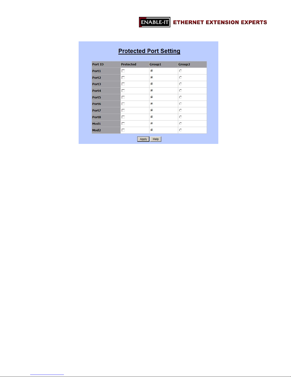
Protected Port
“Protected Port” isolates a protected port from its neighbor ports and other ports in
different protected groups. However, it is allowed for a protected port to communicate
with other unprotected ports. By setting up protected ports, it is able to ensure that
there is no traffic, such as unicast, broadcast, or multicast, between protected ports on
the 8950 Gigabit IP DSLAM.
This function provides two protected port groups. Users are able to choose ports
and assign to either group 1 or group 2.
- Options:
Protected
Click on the corresponding checkbox to select a port.
Group1
Click on the corresponding radio button for assigning a group.
Group2
Click on the corresponding radio button for assigning a group.
Page 23
All Rights Reserved 1997 - 2015 Enable-IT, Inc. Page 23 of 119
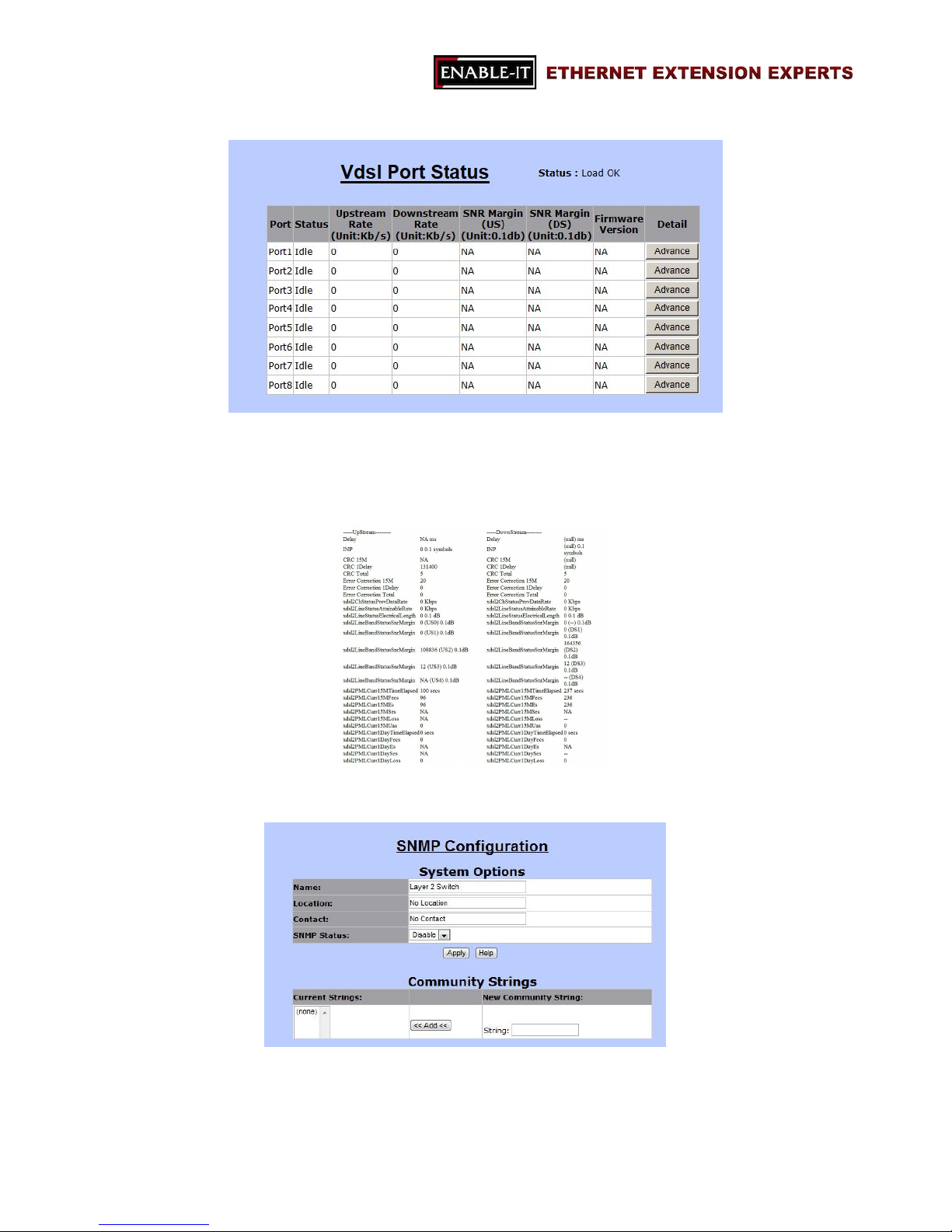
VDSL Port Status
“VDSL Port Status” allows users to monitor the current information of each VDSL port,
such as, status, upstream rate, downstream rate, SNR margins for upstream and
downstream, and firmware version. In addition, it includes “Advance” button for
checking the details of the selected port in another window, as the following.
3.1.5 SNMP Configuration
“SNMP” stands for “Simple Network Management Protocol”, which is a standard protocol
for managing network devices. SNMP is used commonly in Network Management
Systems (as known as, NMS) to monitor network devices. In addition, MIBs
Page 24
All Rights Reserved 1997 - 2015 Enable-IT, Inc. Page 24 of 119
(Management Information Bases) is a kind of file which is used to store all the data of
managed network devices in NMS according to SNMP standard protocols.
8950 Gigabit IP DSLAM supports three versions of SNMP: SNMPv1, SNMPv2c and
SNMPv3. In SNMP Configuration page, it includes the followings sections.
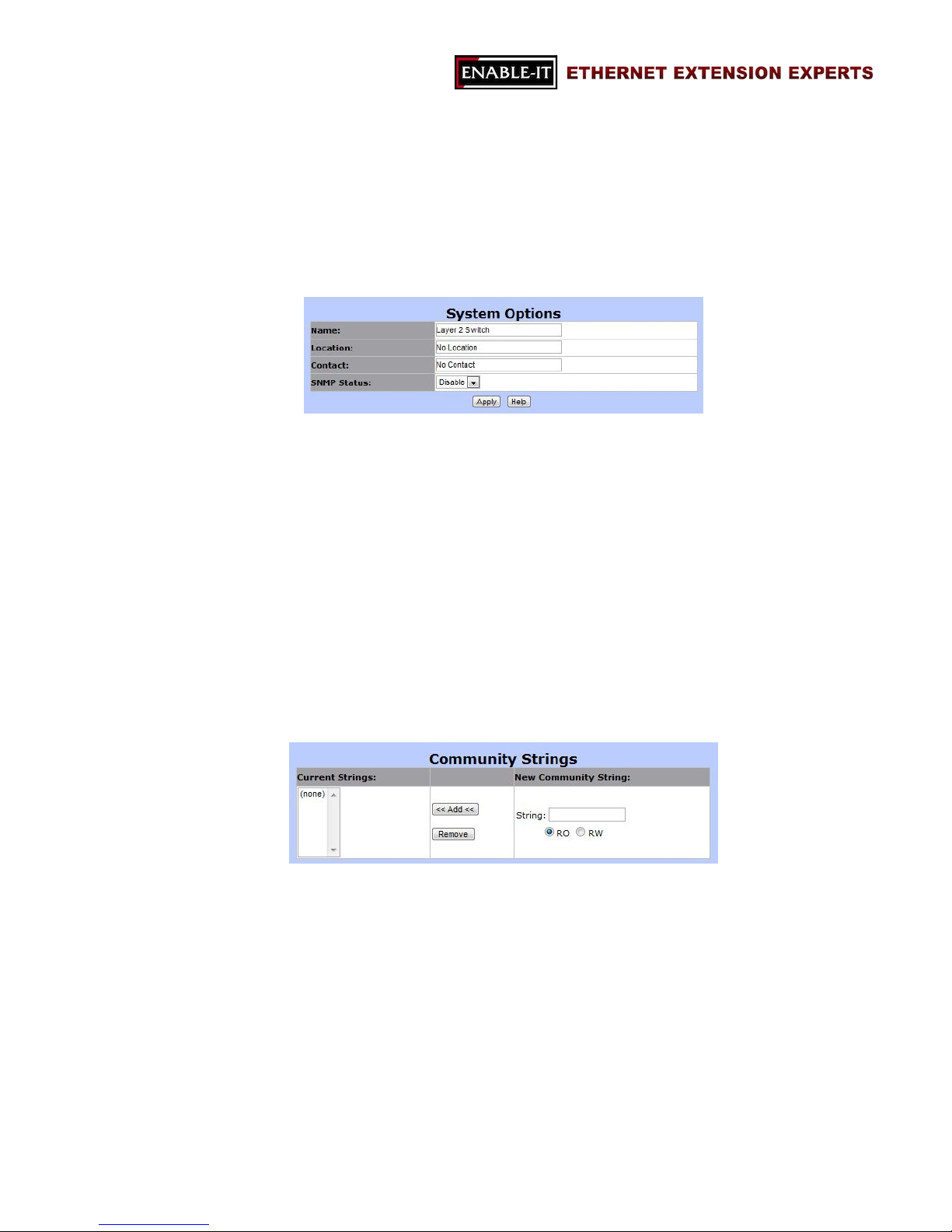
System Options
- Name
The name of the 8950 Gigabit IP DSLAM
- Location
The location of the switch
- Contact
The contact information (the name of a person or organization)
- SNMP Status
Options: Enable or Disable
This option is for enabling or disabling SNMP function.
Community Strings
This section is for setting up the password for accessing SNMP system.
- Current Strings
The list of existing password strings
- New Community String
For the information of a new password
String: password
Options: RO (read only) or RW (read and write)
- Add
Add button: for adding new information on the right hand side of the table
to the community list.
Page 25
All Rights Reserved 1997 - 2015 Enable-IT, Inc. Page 25 of 119
- Remove
Remove button: for removing a password from the left hand side of the
table.
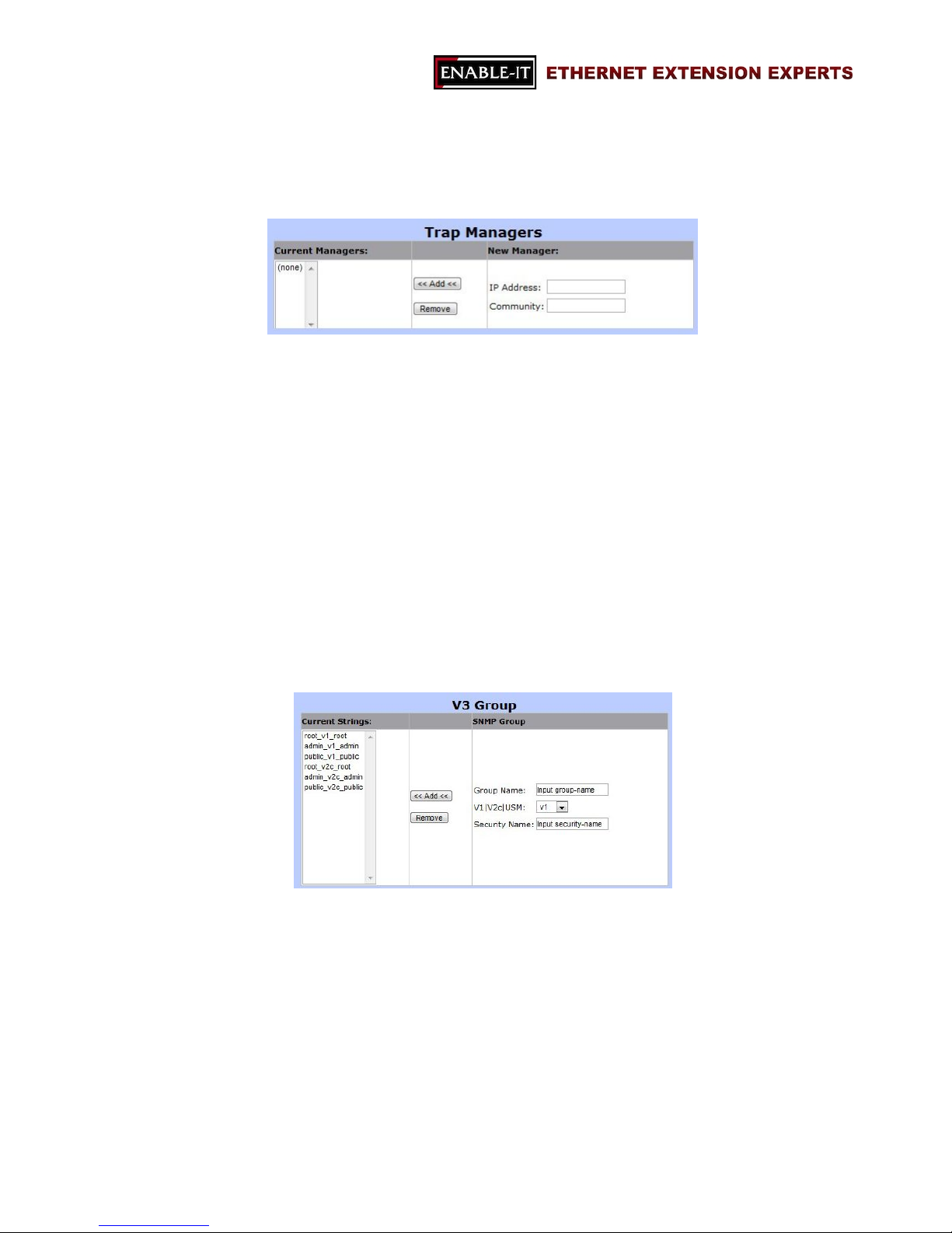
Trap Manager
- Current Managers
The list of existing SNMP servers.
- New Manager
The information of new trap manager.
IP Address: the IP address of the trap manager.
Community: the password for accessing the trap manager.
- Add
For adding new manager.
- Remove
For removing the information of existing manager.
SNMPv3 Group
- Current Strings
The list of current SNMPv3 groups.
- SNMP Group
Group Name: the name of the SNMPv3 group.
V1/V2c/USM: the security model of this group.
Security Name: the security name string of this group.
- Add
For adding new SNMPv3 group.
- Remove
Page 26
All Rights Reserved 1997 - 2015 Enable-IT, Inc. Page 26 of 119
For removing an existing SNMPv3 group.
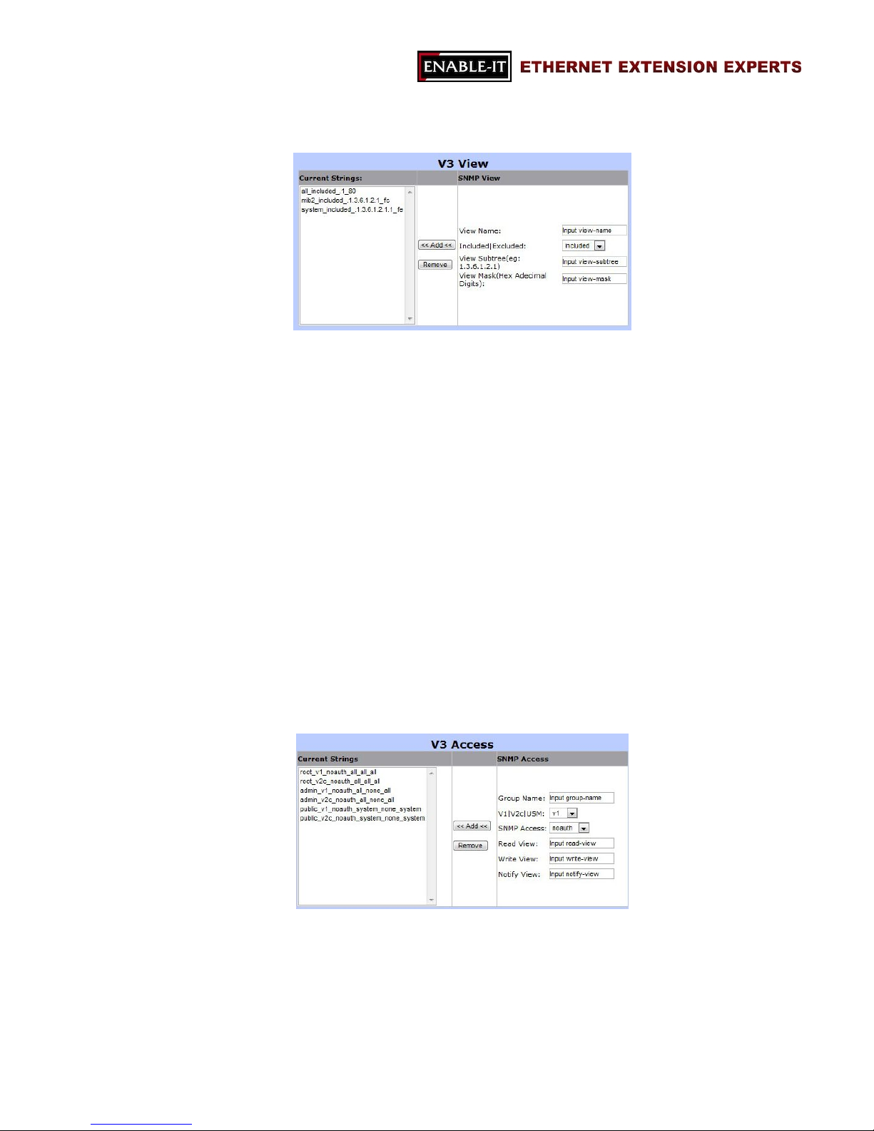
SNMPv3 View
“SNMPv3 view” is to offer or deny access to the complete features or parts of
features of the 8950 Gigabit IP DSLAM.
- Current Strings
The name of current SNMPv3 views.
- SNMP View
View Name: the name of the new SNMPv3 view.
Included/Excluded: the OID should be included or excluded from the
SNMP view.
View Subtree: the feature OID of this view.
View Mask: the subnet mask of this view.
- Add
For adding the new SNMPv3 view.
- Remove
For removing a selected SNMPv3 view from the current strings table.
SNMPv3 Access
“SNMPv3 Access” section is for managing SNMPv3 access control, which is
different from the access control defined by SNMPv1 and SNMPv2. SNMPv3
access sets up SNMP access levels based on contexts, groups and users, rather
than on IP addresses and community strings.
- Current Strings
Page 27
All Rights Reserved 1997 - 2015 Enable-IT, Inc. Page 27 of 119
The list of current SNMPv3 access list
- SNMP Access
Group Name: the group name of the new SNMPv3 access
V1/V2c/USM: the security model
V1: Reserved for SNMPv1
V2c: Reserved for SNMPv2c
USM: User-based Security Model
SNMP Access: the security model
Options: NoAuth/ Auth/ Authpriv
NoAuth: None authentication and none privacy
Auth: Authentication and none privacy
Authpriv: Authentication and privacy
Read View: the read view name.
Write View: the write view name.
Notify View: the notify view name.
- Add
For adding the new SNMPv3 access
- Remove
For removing an access from Current Strings list
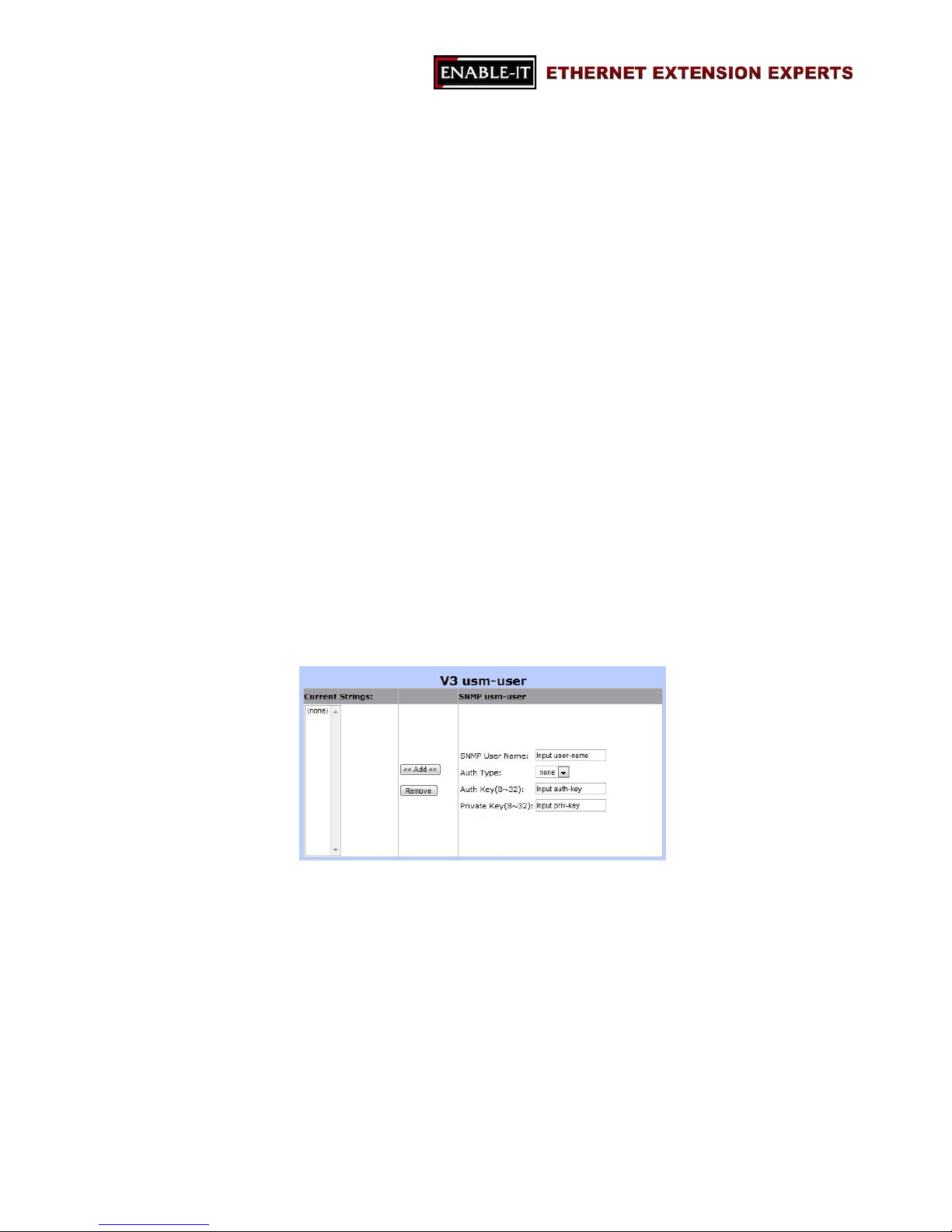
SNMPv3 USM-User
“SNMPv3 USM-User” section is for setting up the details of USM (User-based
Security Model) security model. USM provides different types of security levels
using various authentication and privacy protocols.
- Current Strings
The list of current SNMPv3 USM-user.
- SNMP usm-user
SNMP User Name
the name of new USM user
Auth Type
The authentication type
Page 28

All Rights Reserved 1997 - 2015 Enable-IT, Inc. Page 28 of 119
Options: none or md5
Auth Key
The authentication password of the USM user
Private Key
The password for the privacy protocol type
- Add
For adding the new SNMPv3 USM-user
- Remove
For removing a SNMPv3 USM-user from the current list
Page 29
All Rights Reserved 1997 - 2015 Enable-IT, Inc. Page 29 of 119
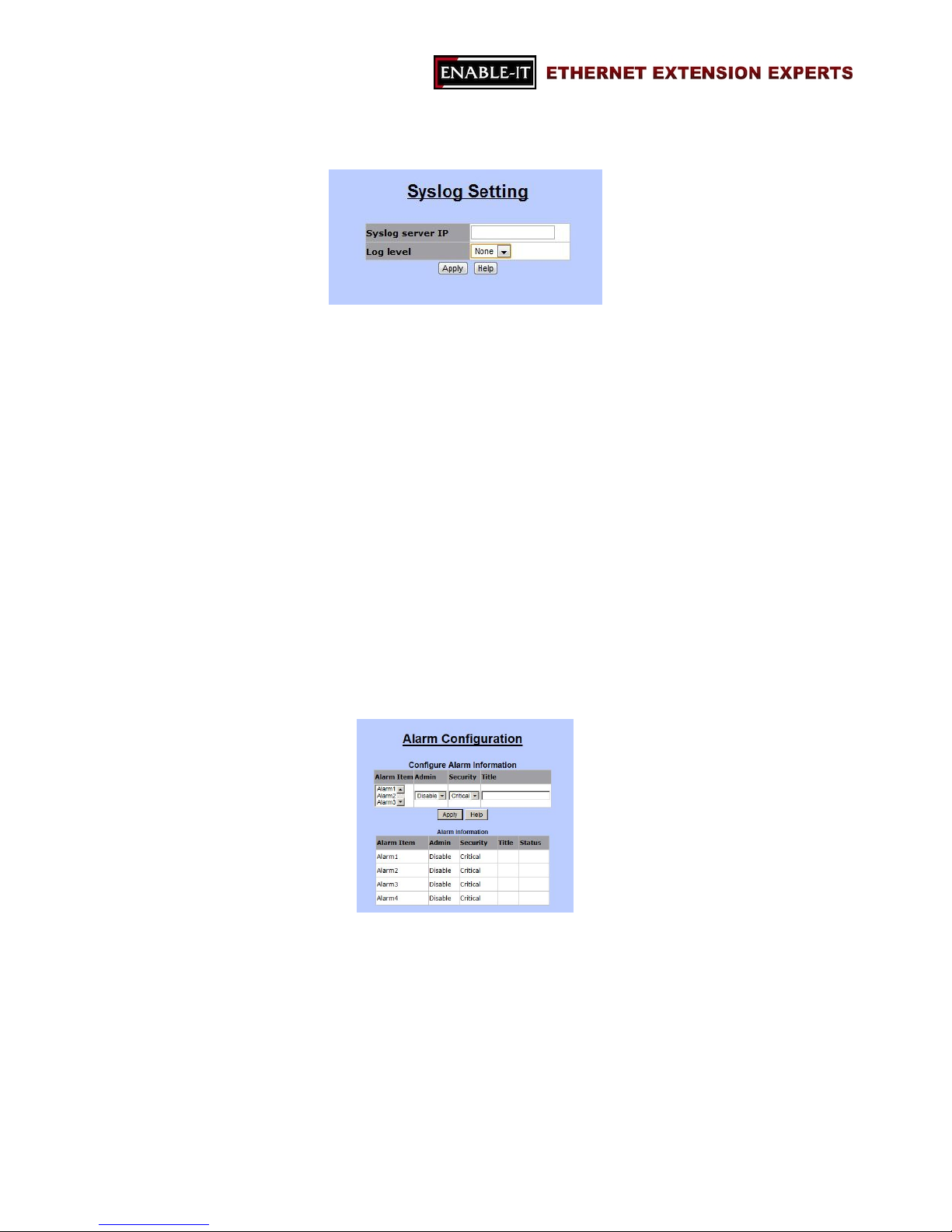
3.1.6 Syslog Setting
“Syslog” function is supported in this 8950 Gigabit IP DSLAM system. The system will
send logs to a remote log system. In this system, three events will be reported to the
remote log system: cold start, warm start and link change. The followings are
necessary for connecting the remote syslog server.
Syslog server IP: the IP address of the remote syslog server IP.
Log level:
Options: None, Major, or All
None: never send syslog message to syslog server.
Major: only send major syslog message to syslog server.
Link up or down
System warm start or cold start
All: send all syslog messages to syslog server.
3.1.7 Alarm Configuration
“Alarm Configuration” is distinguished into two tables: Configure Alarm Information and
Alarm Information. Users are able to setup alarms and monitor alarm status.
Configure Alarm Information (configuration section)
- Alarm Item
Total of four alarms can be set in the 8950 Gigabit IP DSLAM
- Admin
Options: Disable or Enable
Page 30
All Rights Reserved 1997 - 2015 Enable-IT, Inc. Page 30 of 119
- Security
The level of the alarm
- Title
The name of the alarm
Alarm Information (monitor section)
- Alarm Item
- Admin
- Security
- Title
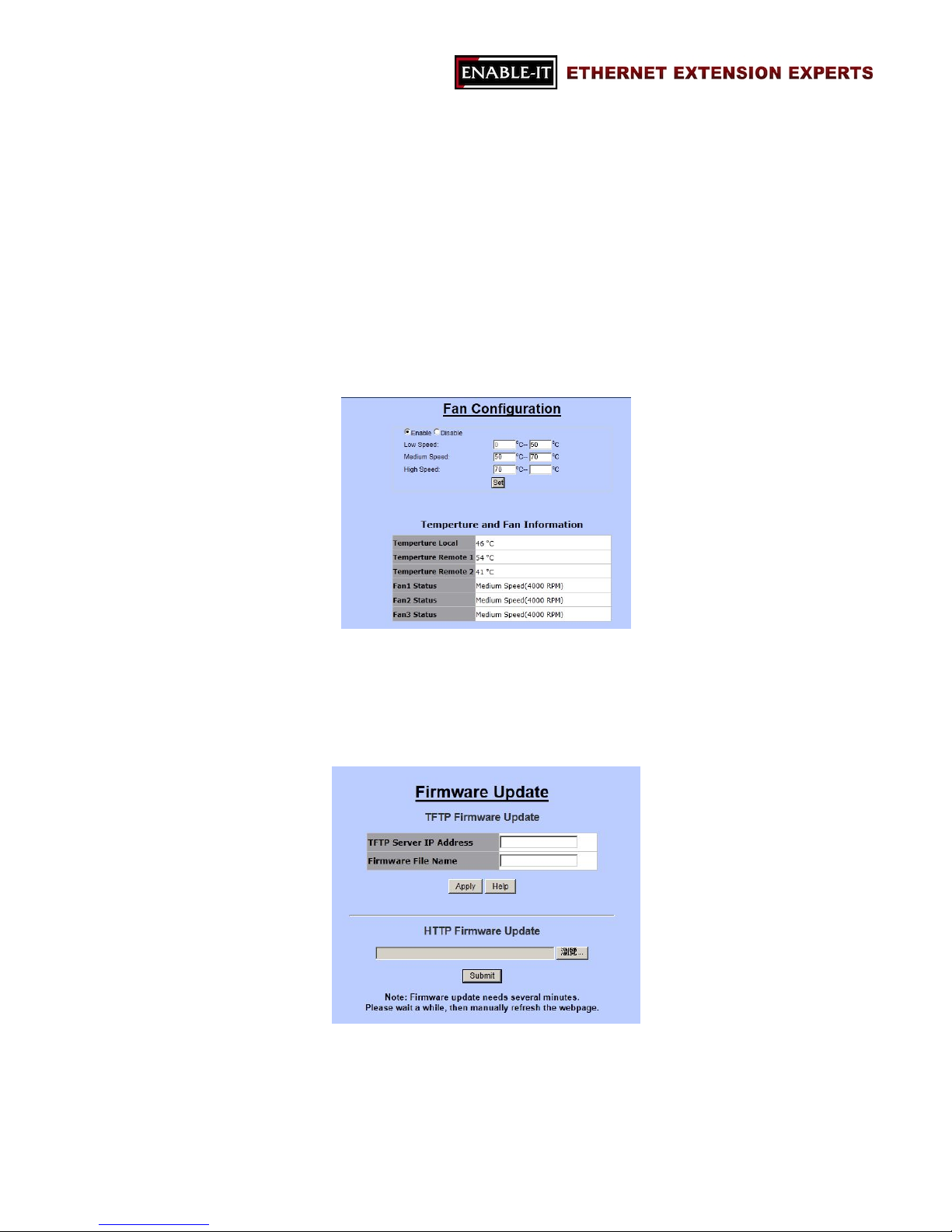
3.1.8 Temperatures & Fan Setting
“Temperatures & Fan Status” allows users to monitor the real-time information of the
8950 Gigabit IP DSLAM’s temperatures and FANs.
3.1.9 Firmware Update
“Firmware Update” allows users to upgrade firmware by themselves. Users are able to
choose upgrading firmware through TFTP or HTTP.
Page 31
All Rights Reserved 1997 - 2015 Enable-IT, Inc. Page 31 of 119
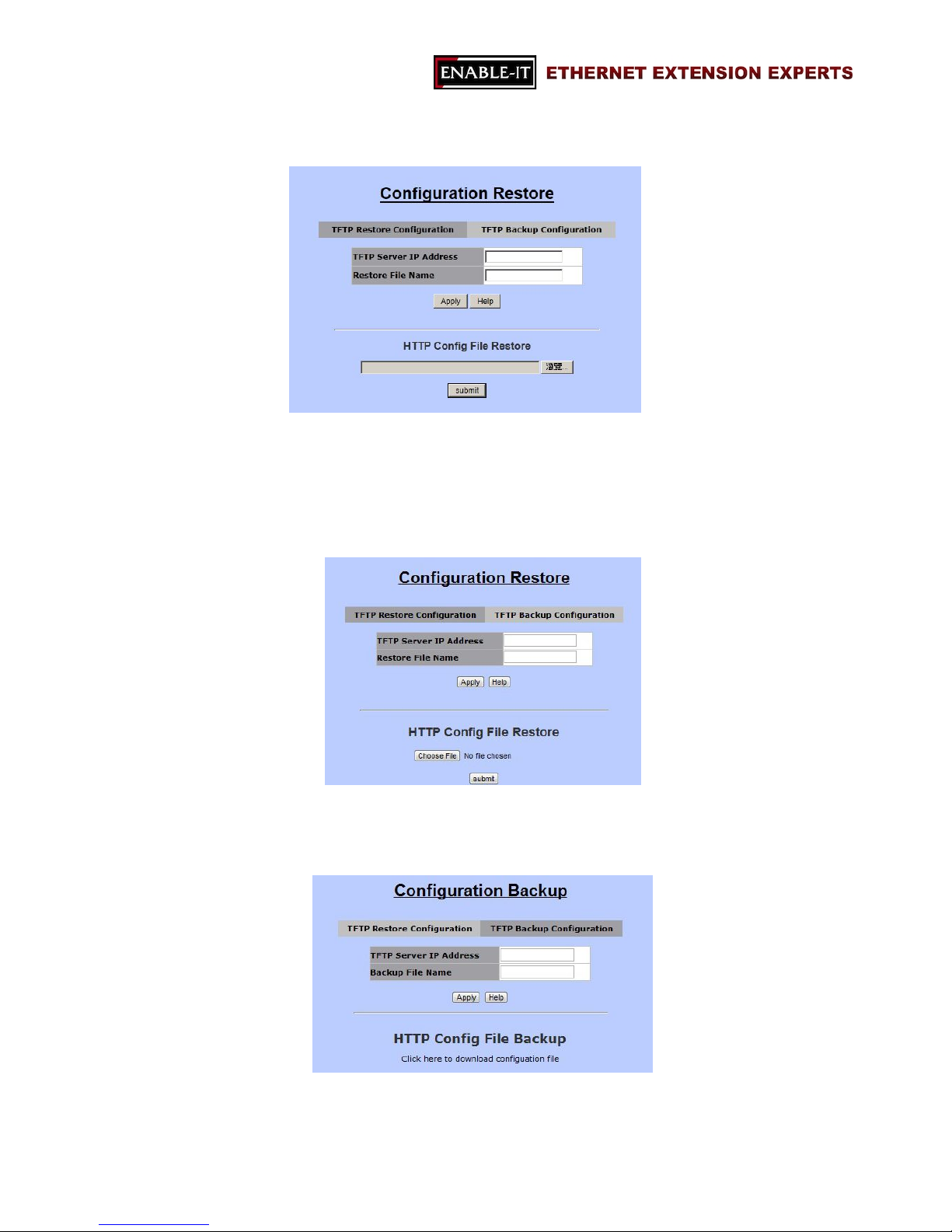
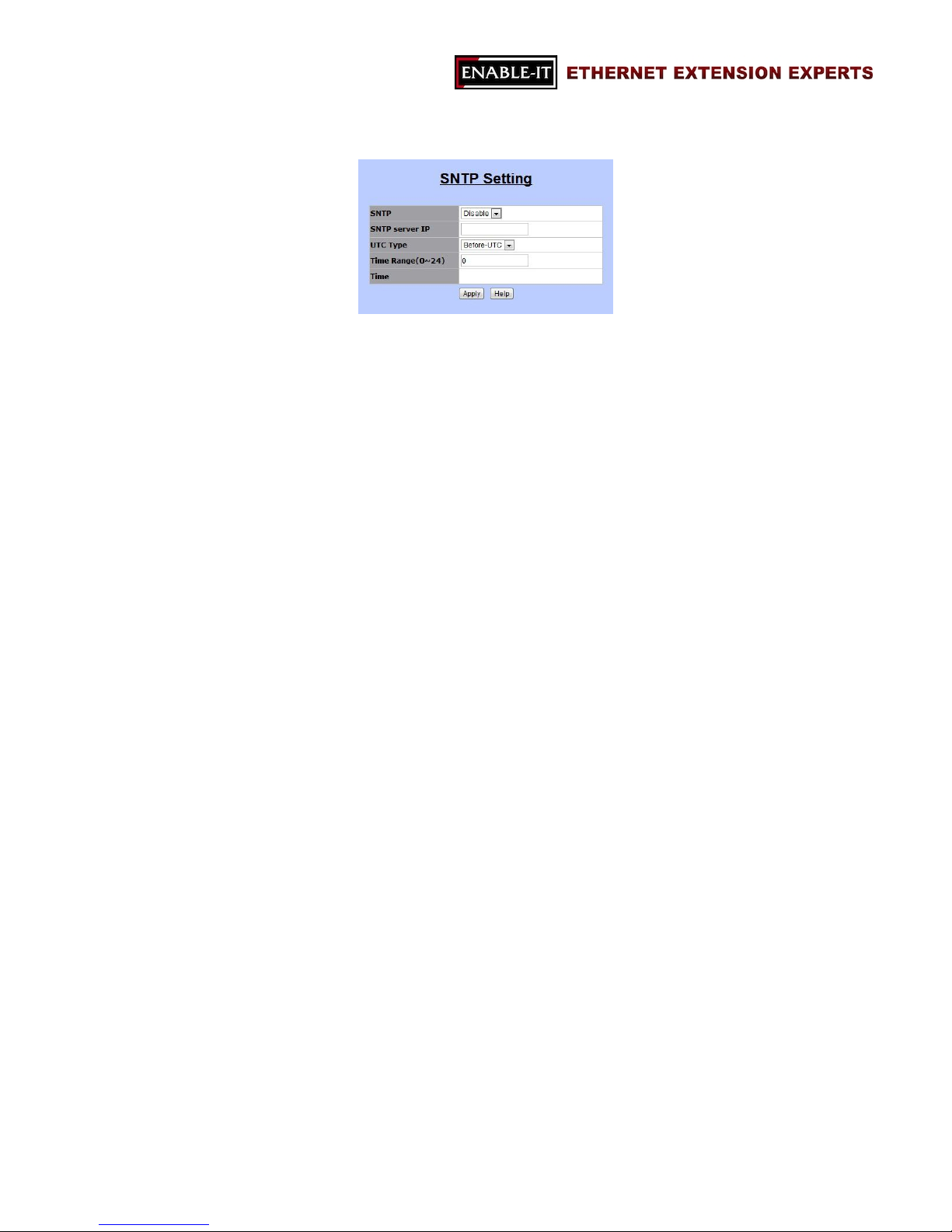
3.1.10 Configuration Backup
Users are able to load or backup configurations via “Configuration Restore” function.
This function includes two tabs: “TFTP Restore Configuration” and “TFTP Backup
Configuration”.
TFTP Restore Configuration
This section is for load the settings from a configuration file. Users are able to
upload the settings by TFTP or HTTP.
TFTP Backup Configuration
This area allows users to download the current configuration through TFTP or HTTP.
Page 32
All Rights Reserved 1997 - 2015 Enable-IT, Inc. Page 32 of 119
3.1.11 SNTP Setting
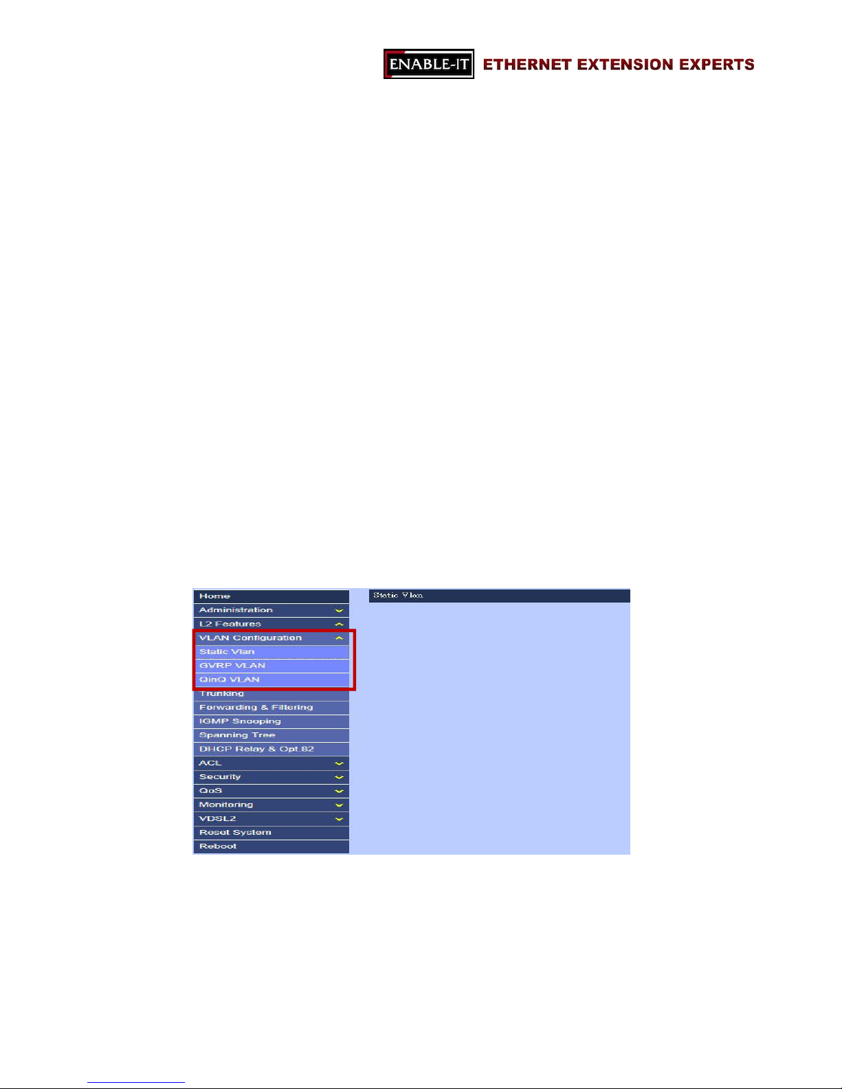
SNTP stands for “Simple Network Time Protocol”. SNTP is a simpler version of
“Network Time Protocol” (NTP), which is a system for synchronizing the clocks of
network computer systems. By enabling SNTP function, users are able to configure
this switch to send time synchronization requests to the assigned servers with servers’ IP
addresses.
- SNTP
To enable or disable SNTP feature.
Options: Enable or Disable.
- SNTP server IP
The IP address of the assigned SNTP server.
- UTC Type
To decide the time zone.
Options:
After-UTC: UTC+hh (hh: hours)
For example, Taipei (UTC+08), choose “After-UTC”.
Before-UTC: UTC-hh (hh: hours)
For example, San Francisco (UTC-08), choose “Before-UTC”.
- Time Range
This field is for setting up the hour data in “UTC-hh/UTC+hh”.
For example, UTC-08, then, choose “Before-UTC” in UTC type and fill
in “8” in Time Range.
- Time
This section is for displaying the current time once the switch is connected
to the assigned NTP server.
Page 33
All Rights Reserved 1997 - 2015 Enable-IT, Inc. Page 33 of 119
3.2 L2 Features
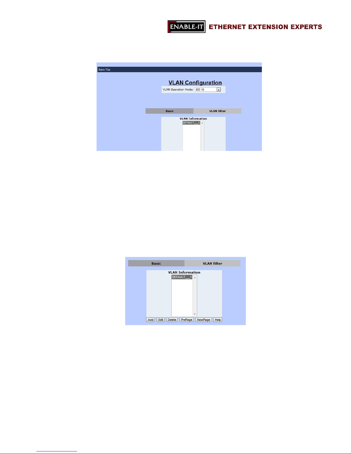
8950 Gigabit 8 Port IP DSLAM offers a flexible L2 features, as the following functions:
VLAN Configuration
Trunking
Forwarding & Filtering
IGMP Snooping
Spanning Tree
DHCP Relay & Opt.82
3.2.1 VLAN Configuration
“VLAN” stands for “Virtual Local Area Network” or “virtual LAN”. It is a concept of
separating and grouping LAN segments by a common set of requirements. VLAN
presents couple benefits, such as, simplifying network design, enhancing bandwidth
performance and improving, etc.
The 8950 Gigabit IP DSLAM supports three kinds of VLAN algorithms:
Static VLAN
GVRP VLAN
QinQ VLAN
Page 34
All Rights Reserved 1997 - 2015 Enable-IT, Inc. Page 34 of 119
3.2.1.1 Static VLAN
Static VLAN function allows users to setup and manage VLAN groups manually.
VLAN Operation Mode
- No VLAN
To disable VLAN mode.
- Port-Based VLAN
To setup VLAN groups by ports.
- 802.1Q VLAN
To setup VLAN groups by 802.1Q VLAN tags.
Basic
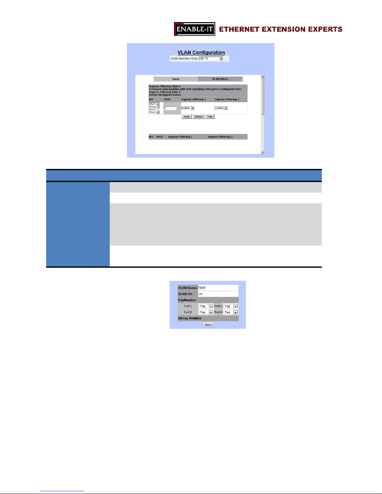
“VLAN Information” displays all VLAN groups stored already. The following buttons
allow users to manage VLAN groups.
Note: The VLAN mode of VLAN operation mode is the global setting of “Basic” and
“VLAN Filter”.
- Add
Page 35
All Rights Reserved 1997 - 2015 Enable-IT, Inc. Page 35 of 119
To create a new VLAN group.
Name Description
VLAN Name The name of this VLAN group
VID VLAN ID
VLAN Members There are three columns in this section.
Ports (left-hand side): Port1 ~ Port8, Mod1, Mod2
Add or Remove (middle): for adding or removing a port
Selected Ports (right-hand side): the VLAN group members
CPU Port Click on this checkbox to choose this VLAN group as the
management group of this 8950 Gigabit IP DSLAM.
Click “Apply” to set up tag mode.
- Edit
To change the settings of an existing VLAN group.
- Delete
To remove an existing VLAN group.
- PrePage
To move to the previous page of VLAN information table.
- NextPage
To move to the following page of VLAN information table.
- Help
To open FAQ page of VLAN configuration.
Page 36
All Rights Reserved 1997 - 2015 Enable-IT, Inc. Page 36 of 119
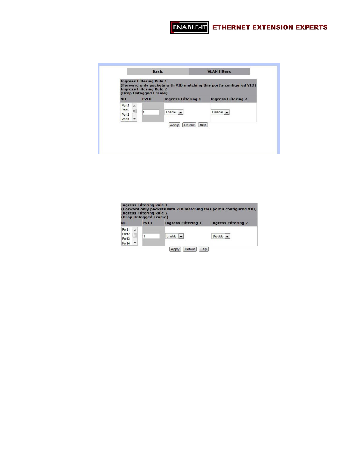
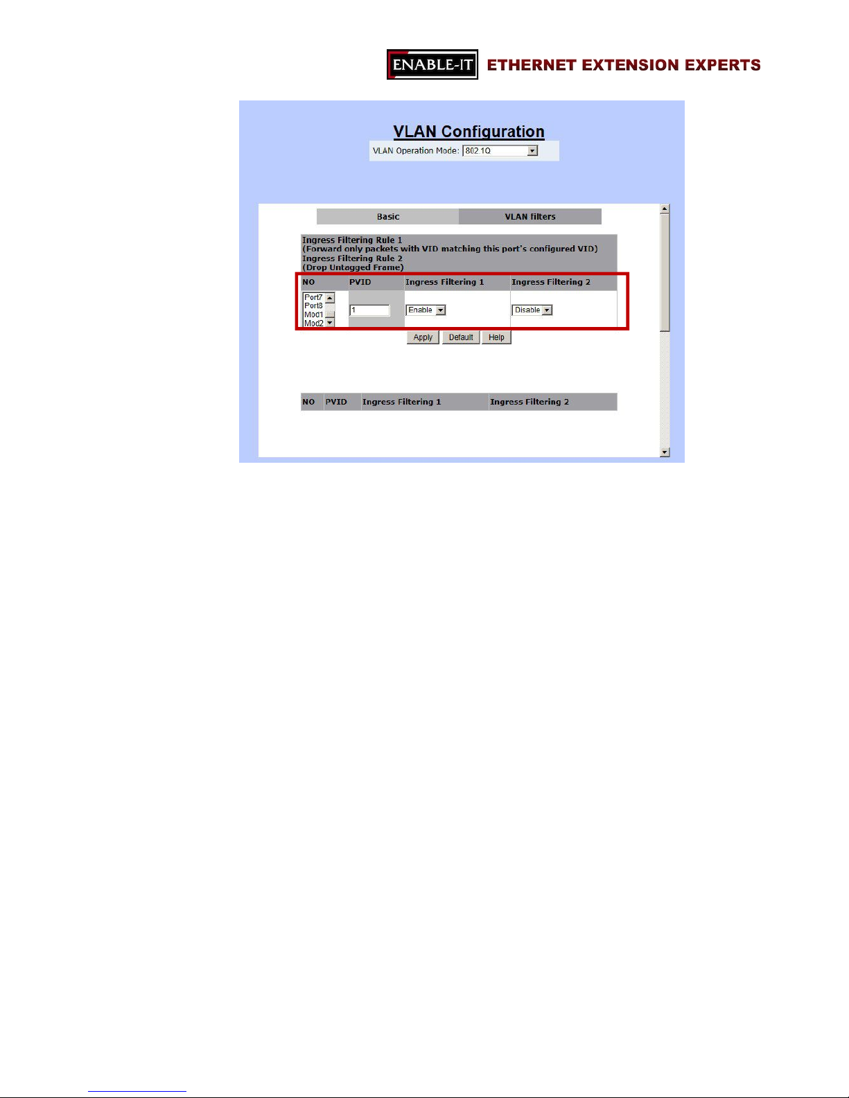
VLAN filter
VLAN filter function is for setting the filtering rules for all ports (Port1 ~ Port8, Mod1
and Mod2).
Users are able to define filtering rules for each port.
- NO
The list of available ports.
Click on a port to change the details. In addition, the current setups will
be showed in a different table right next to the setup table.
Page 37
All Rights Reserved 1997 - 2015 Enable-IT, Inc. Page 37 of 119
- PVID
The VLAN ID of ingress packets.
Two filtering rules are available in VLAN Filtering function of this 8950 Gigabit IP
DSLAM.
- Ingress Filtering 1
Only these ingress packets with the assigned VLAN ID are able to pass
through this port.
Options: Enable or Disable (disable filtering function)
- Ingress Filtering 2
Enabling this rule will drop all untagged packets.
Options: Enable (only packets with the assigned VLAN ID can pass
through this port) or Disable (accept all packets)
Page 38
All Rights Reserved 1997 - 2015 Enable-IT, Inc. Page 38 of 119
3.2.1.2 GVRP VLAN
GVRP stands for “GARP (Generic Attribute Registration Protocol) VLAN Registration
Protocol” or “Generic VLAN Registration Protocol”. GVRP VLAN method follows IEEE
802.1Q specification and defines tagging frames with VLAN configuration data. This
meaning allows 8950 Gigabit IP DSLAM to exchange VLAN configuration information
with other network devices dynamically.
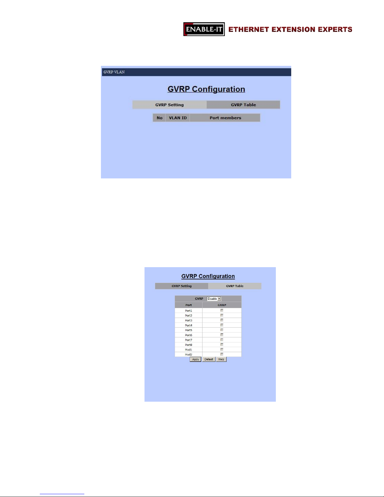
- GVRP Setting
For setting up GVRP configurations
GVRP
Options: Enable or Disable
Port & GVRP
Port1 ~ Port8, Mod1, Mod2 & corresponding checkbox.
Click on the checkboxes to choose GVRP group members.
Page 39

All Rights Reserved 1997 - 2015 Enable-IT, Inc. Page 39 of 119
Apply
To save the modifications.
Default
To restore default settings.
Help
To open the FAQ page of GVRP VLAN.
- GVRP Table
This table is for displaying current GVRP VLAN information.
- GVRP will learn VLAN ID and its group member automatically. This table will
show this information.
Page 40
All Rights Reserved 1997 - 2015 Enable-IT, Inc. Page 40 of 119
3.2.1.3 QinQ VLAN
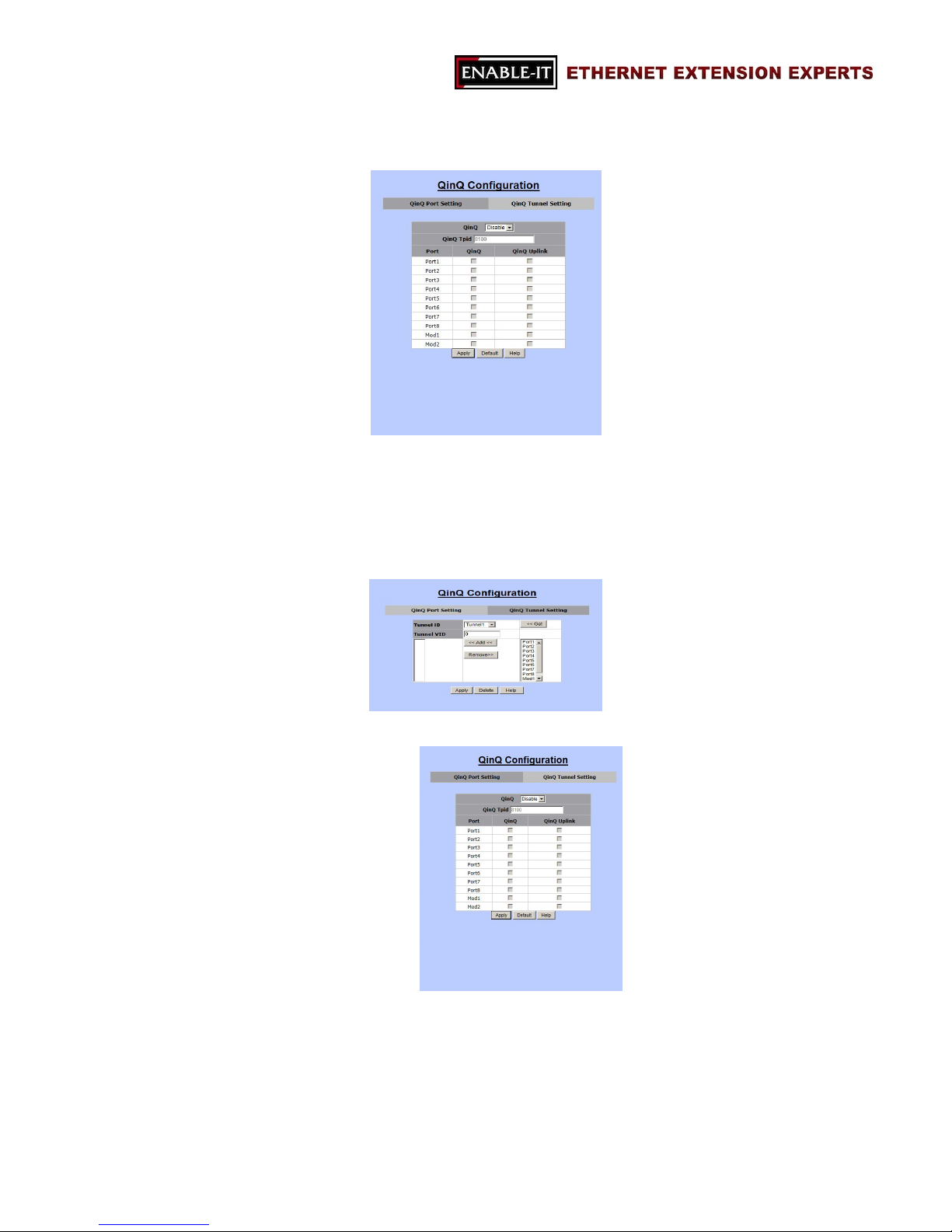
QinQ VLAN function allows users or service providers to separate traffic service for
different customers by adding service provide VLAN tags and customer VLAN IDs. In
this function, settings are divided into two parts:
QinQ Port Setting
QinQ Tunnel Setting
- QinQ Port Setting
This section is for setting up QinQ mode, TPID, and group members.
The followings are the details that are required to be filled in for setting
QinQ function.
QinQ: Disable or Enable
Page 41
All Rights Reserved 1997 - 2015 Enable-IT, Inc. Page 41 of 119
QinQ TPID:
TPID stands for “Tag Protocol Identifier”.
TPID is the Ethertype value for 802.1Q encapsulation.
Standard Ethertype value: 0x8100 (Default value)
Range: 0x0800 ~ 0xFFFF (hexadecimal value).
Port Table:
QinQ: for choosing which port should be enabled with QinQ
mode.
QinQ Uplink: for setting up an uplink port of this QinQ group.
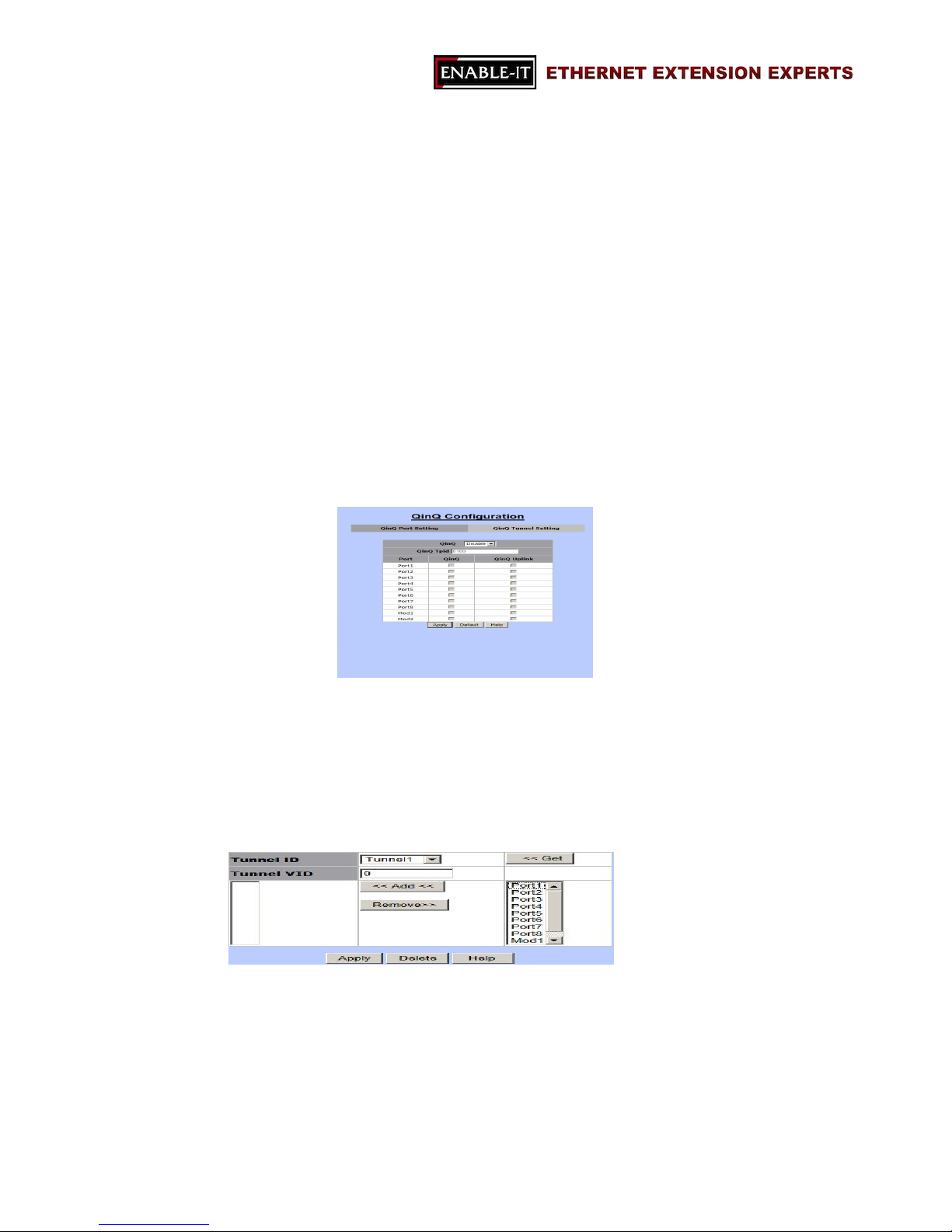
- QinQ Tunnel Setting
“QinQ Tunnel” is for service providers who carry traffic of multiple customers
across their networks and are required to maintain VLAN and Layer 2 protocol
configurations for each customer.
Tunnel ID
Tunnel VID
Port List: choose user port and uplink port.
Page 42
All Rights Reserved 1997 - 2015 Enable-IT, Inc. Page 42 of 119
3.2.2 Trunking
Trunking function allows users to combine several ports or connections together to
create one single connection which has a higher and faster connection speed.
“Trunking” is also called “Link Aggregation”. Two trunking techniques are available in
this 8950 Gigabit IP DSLAM:
Static Trunk
LACP
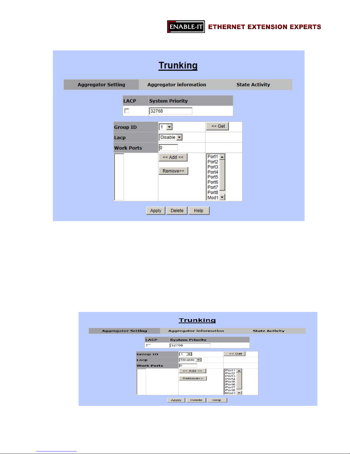
- Aggregator Setting
This section allows users to setup trunking groups and details.
Page 43
All Rights Reserved 1997 - 2015 Enable-IT, Inc. Page 43 of 119
The following information is needed for setting up a trunk group.
LACP (checkbox): for enable or disable LACP algorithm by check on
the checkbox.
System Priority: this value is for identifying the active LACP of this
8950 Gigabit IP DSLAM. (Note: the lowest value presents the highest
priority.)
Trunk Group Table
Group ID: the trunk group ID (1~13)
LACP: Enable or Disable LACP algorithm for this trunk group.
Work Ports: the total port number of the group member. (Please
select the group number in the following port list.)
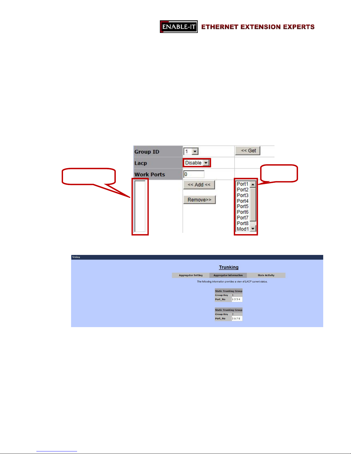
- Aggregator information
This section allows users to review trunk information.
Two data are reviewed in this section:
Group Key: the trunk group ID.
Port No: the port member of this trunk group. (Port1 ~ Port8, Mod1,
Mod2)
Port List
Selected Port List
Page 44
All Rights Reserved 1997 - 2015 Enable-IT, Inc. Page 44 of 119
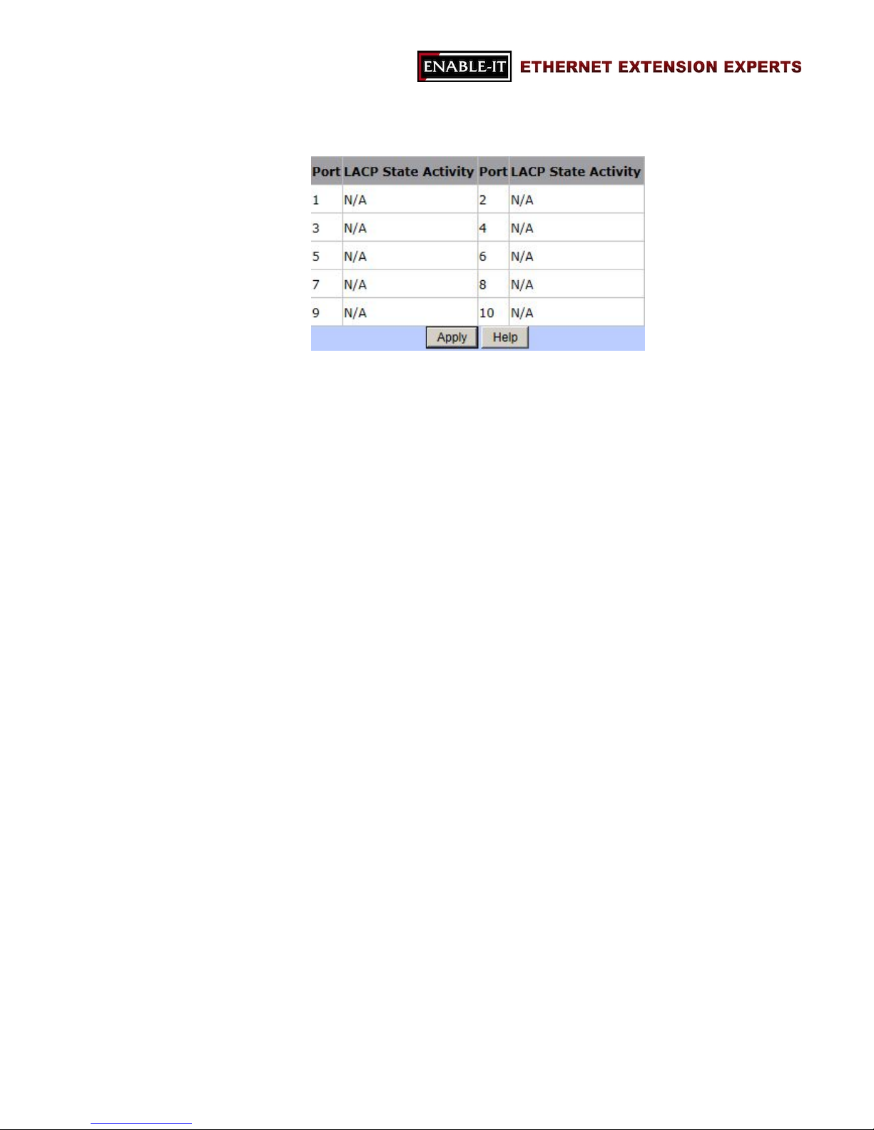
- Static Activity
This area is for setting up LACP mode (active or passive)
Active: the active port will send LACP packets automatically.
Passive: the passive port will not send LACP packets but it will
respond if and only if it receives LACP packets from the other end.
Page 45
All Rights Reserved 1997 - 2015 Enable-IT, Inc. Page 45 of 119
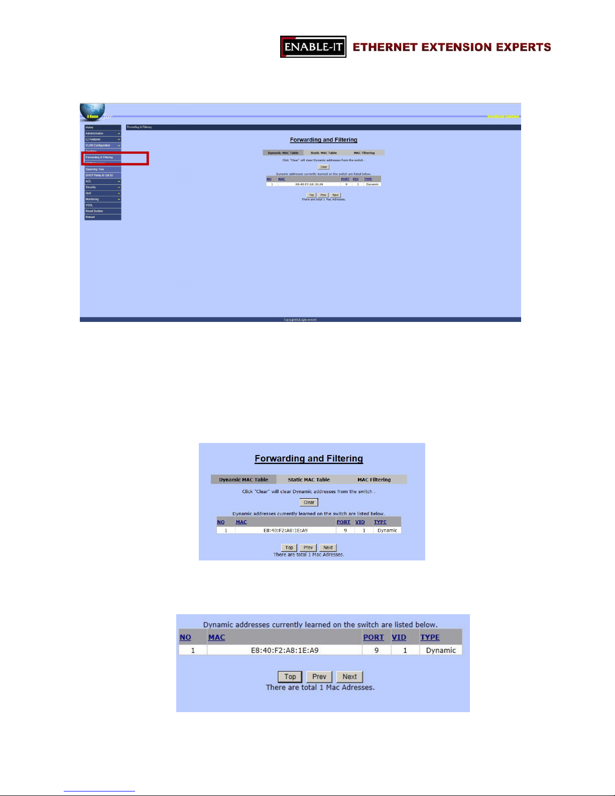
3.2.3 Forwarding & Filtering
“Forwarding & Filtering” function is for users to setup rules about packets. Four ways to
setup these rules:
Dynamic MAC Table
Static MAC Table
MAC Filtering
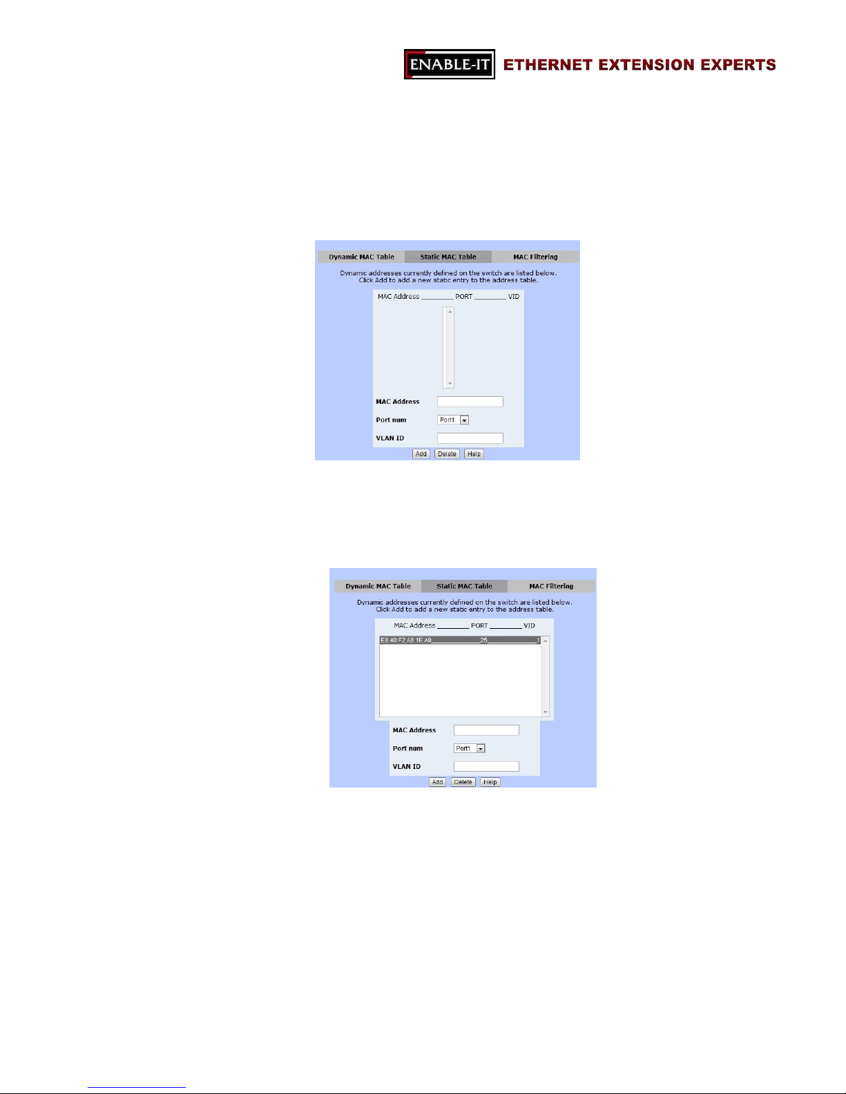
- Dynamic MAC Table
The 8950 Gigabit IP DSLAM will learn devices’ MAC addresses dynamically
and record these addresses into MAC address table. This section will show all
the found MAC addresses as the following table.
Clear: to clear the dynamic MAC address table.
Page 46
All Rights Reserved 1997 - 2015 Enable-IT, Inc. Page 46 of 119
Top: to show the first page of the MAC address table.
Prev: to go to the previous page of the MAC address table.
Next: to go to the next page of the MAC address table. (Note: if there is nothing
showed, it means this is the end page.)
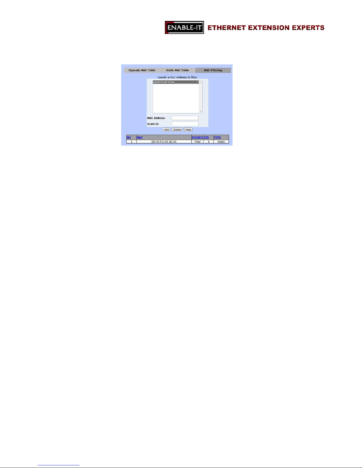
- Static MAC Table
Users are able to fill up the MAC addresses of devices connected to the switch.
By adding a static MAC address, the switch will save the information
permanently and will not attend to learn the MAC address of this device when
the device is online.
Page 47
All Rights Reserved 1997 - 2015 Enable-IT, Inc. Page 47 of 119
- MAC Filtering
Users are able to define and drop unwanted traffic in “MAC Filtering” function.
Page 48
All Rights Reserved 1997 - 2015 Enable-IT, Inc. Page 48 of 119
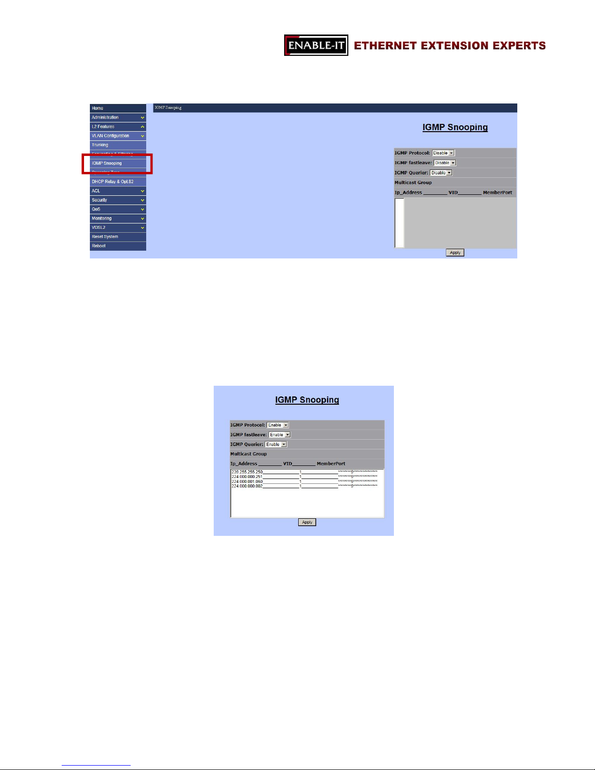
3.2.4 IGMP Snooping
“IGMP” stands for “Internet Group Management Protocol”. IGMP allows hosts and
routers to build multicast group memberships. IGMP snooping presents the process of
IGMP network traffic listening. With this feature, 8950 Gigabit IP DSLAM is able to
listen to IGMP conversation between hosts and routers. The switch is able to maintain
a relation map of links and IP multicast streams.
The following settings are needed in order to allow IGMP snooping work properly.
IGMP Protocol: to enable or disable IGMP function.
IGMP Fastleave: to enable or disable IGMP Fastleave mode.
IGMP Querier: to enable or disable IGMP Querier mode.
Multicast Group: the multicast group list table.
Page 49
All Rights Reserved 1997 - 2015 Enable-IT, Inc. Page 49 of 119
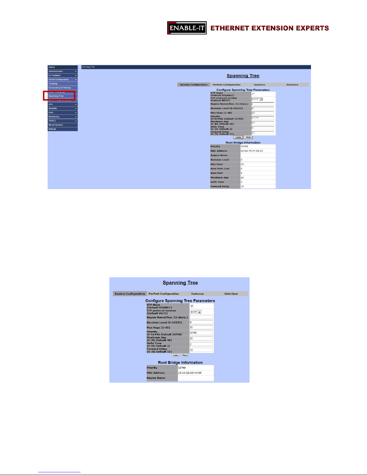
3.2.5 Spanning Tree
Spanning Tree (also known as, STP) is a network protocol which is defined by IEEE
802.1 D standards for preventing bridge loops and broadcast radiation. In addition,
STP allows redundant links to provide automatic backups. Most commonly known STP
algorithms are STP (Spanning Tree Protocol), RSTP (Rapid Spanning Tree Protocol),
and MSTP (Multiple Spanning Tree Protocol). This 8950 Gigabit IP DSLAM supports
both STP and MSTP. In addition, in this Switch, users are able to set up STP either for
the whole system of the Switch or for each individual port.
In Spanning Tree function, there are four major setup pages as the following sections.
- System Configuration
- PerPort Configuration
- Instance
Page 50
All Rights Reserved 1997 - 2015 Enable-IT, Inc. Page 50 of 119
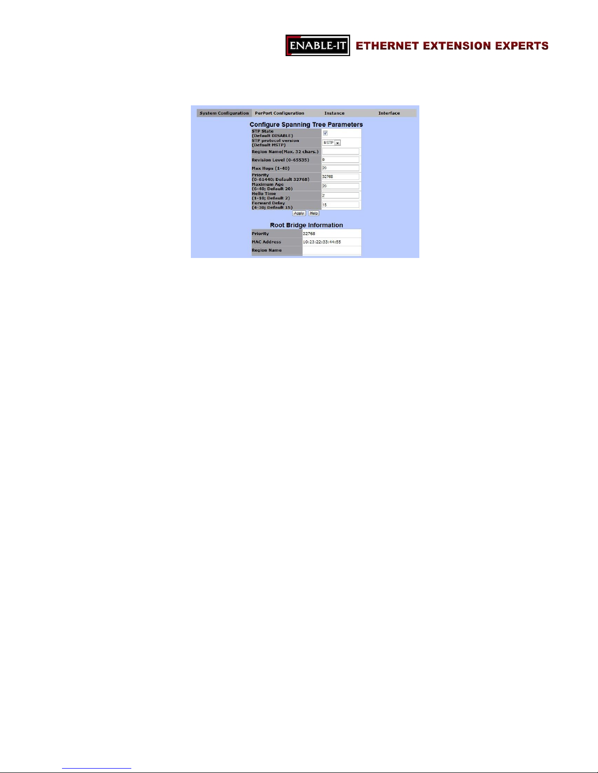
3.2.5.1 System Configuration
“System Configuration” allows users setting up the details of STP function. In addition,
the information of the root node of the STP will be displayed in this page.
- Configure Spanning Tree Parameters
STP State
To enable or disable STP function.
Note: to enable STP function, users are required to click on this checkbox
and press “Apply” button. Then, after the saving process is completed,
users are able to fill up the rest of the information.
STP protocol version
STP or MSTP
Region Name
Name of STP tree
Revision Level
The level of STP tree
Max Hops
Hop number
Priority
Maximum Age
The waiting time (seconds) before the switch attempts to reconfigure.
Hello Time
The time (seconds) the switch will send BPDU packets to check STP
current status.
Forward Delay
- Root Bridge Information
Priority
MAC Address
Region Name
Page 51
All Rights Reserved 1997 - 2015 Enable-IT, Inc. Page 51 of 119
Revision Level
Max Hops
Root Path Cost
Maximum Age
Hello Time
Forward Delay
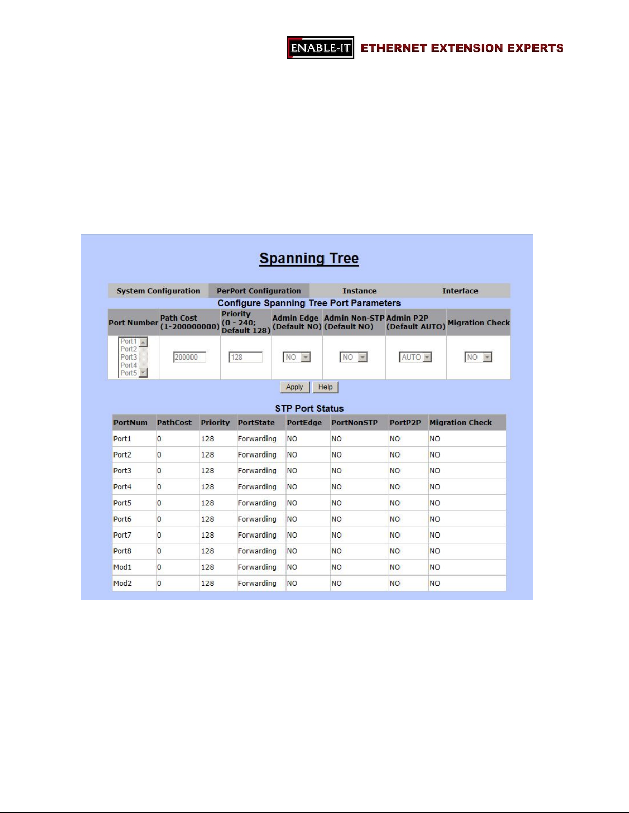
3.2.5.2 PerPort Configuration
“PerPort Configuration” is for setting up Spanning Tree mode for each individual port.
Page 52
All Rights Reserved 1997 - 2015 Enable-IT, Inc. Page 52 of 119
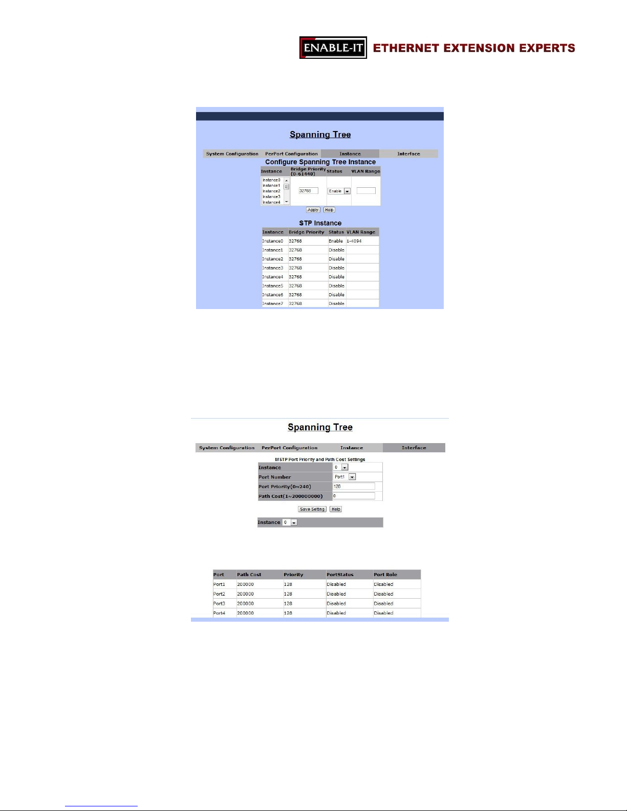
3.2.5.3 Instance
“Instance” function is a part of MSTP function. MSTP allows users to map a group of
VLANs into a single Multiple Spanning Tree Instance (MSTI). This means the spanning
tree protocol is applied separately for a set of VLANs instead of the whole network.
3.2.5.4 Interface
“Interface” is for MSTP, too. In this section, users are allowed to configure MSTP port
priority and path cost settings of “Instance”.
Page 53
All Rights Reserved 1997 - 2015 Enable-IT, Inc. Page 53 of 119
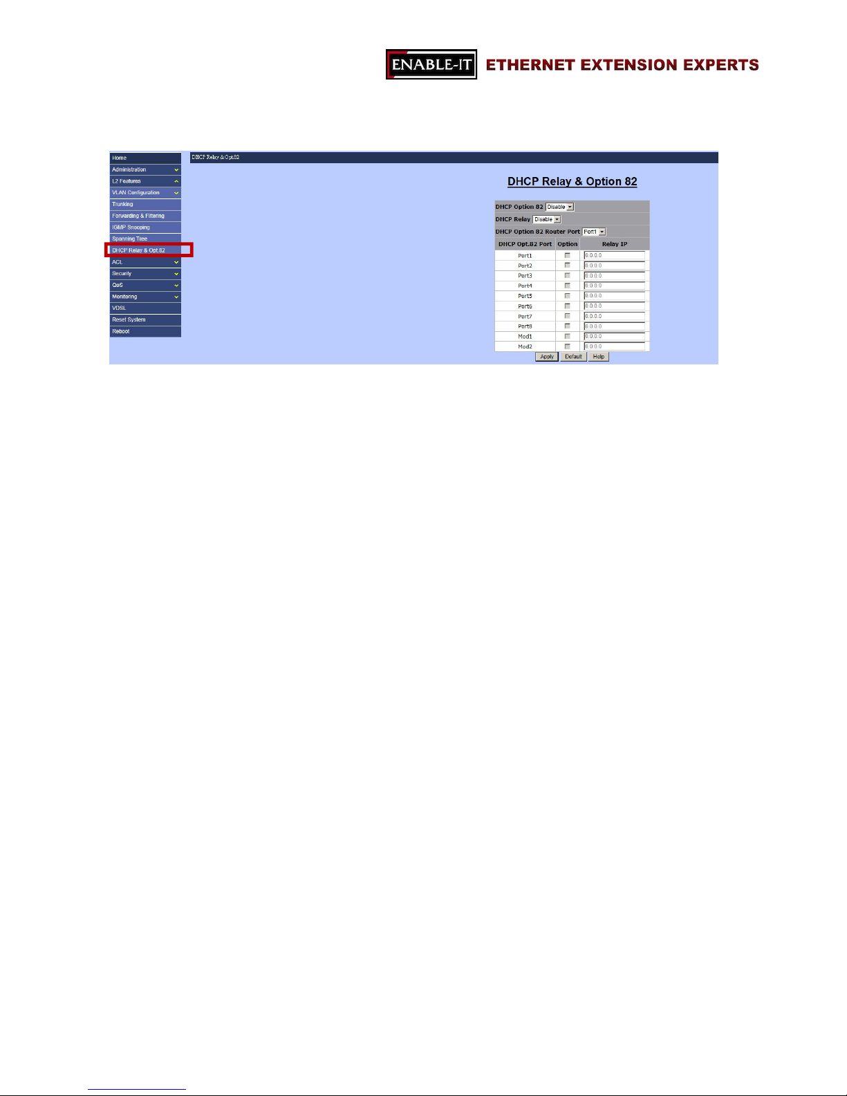
3.2.6 DHCP Relay & Opt.82
“DHCP” stands for “Dynamic Host Configuration Protocol”, which is a network protocol
that is for configuring network devices dynamically so these devices can communicate
on an IP network. It is a service that runs at the application layer of TCP/IP protocol
stack to assign IP addresses to its clients dynamically.
“DHCP Relay” will forward DHCP broadcasts to multiple DHCP servers in different
subnets using unicasts. By doing so, DHCP clients on subnets not directly served by
DHCP servers can communicate with DHCP servers. In addition, “DHCP Relay
Information Options 82”, is defined in RFC 3046 and RFC 3993, allows a DHCP Relay
agent to insert circuit specific information to a request which is forwarded to a DHCP
server.
Page 54
All Rights Reserved 1997 - 2015 Enable-IT, Inc. Page 54 of 119
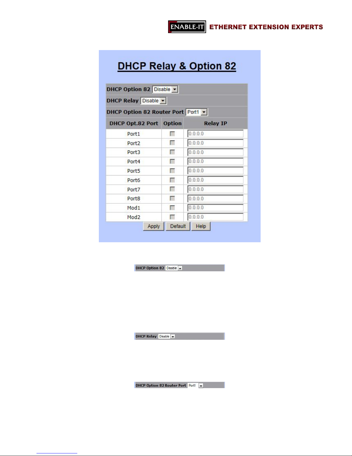
3.2.6.1 DHCP Option 82
Users are allowed to enable or disable DHCP Option 82 by choosing the options in the
drop-down menu. To setup DHCP Option 82 for this switch, users are required to
enable this option first.
3.2.6.2 DHCP Relay
DHCP Relay is for enabling or disabling DHCP Relay function.
3.2.6.3 DHCP Option 82 Router Port
“DHCP Option 82 Router Port” allows users to choose the relay port for DHCP Option 82
feature. Users are able to specific one port between Port1 to Port8 or Mod1 to Mod2.
Page 55
All Rights Reserved 1997 - 2015 Enable-IT, Inc. Page 55 of 119
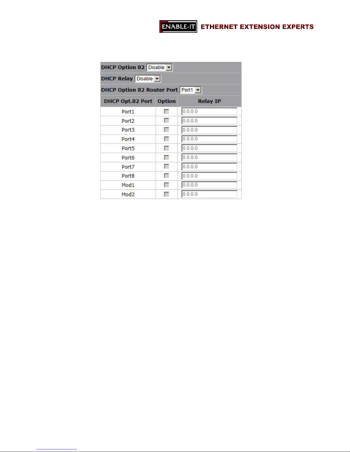
3.2.6.4 DHCP Opt. 82 Port Table
This section is for defining DHCP Option 82 and port information.
- Option: the checkbox for enabling or disabling DHCP Relay Information Option 82
function.
- Relay IP: for assign the IP address of the port.
Page 56
All Rights Reserved 1997 - 2015 Enable-IT, Inc. Page 56 of 119
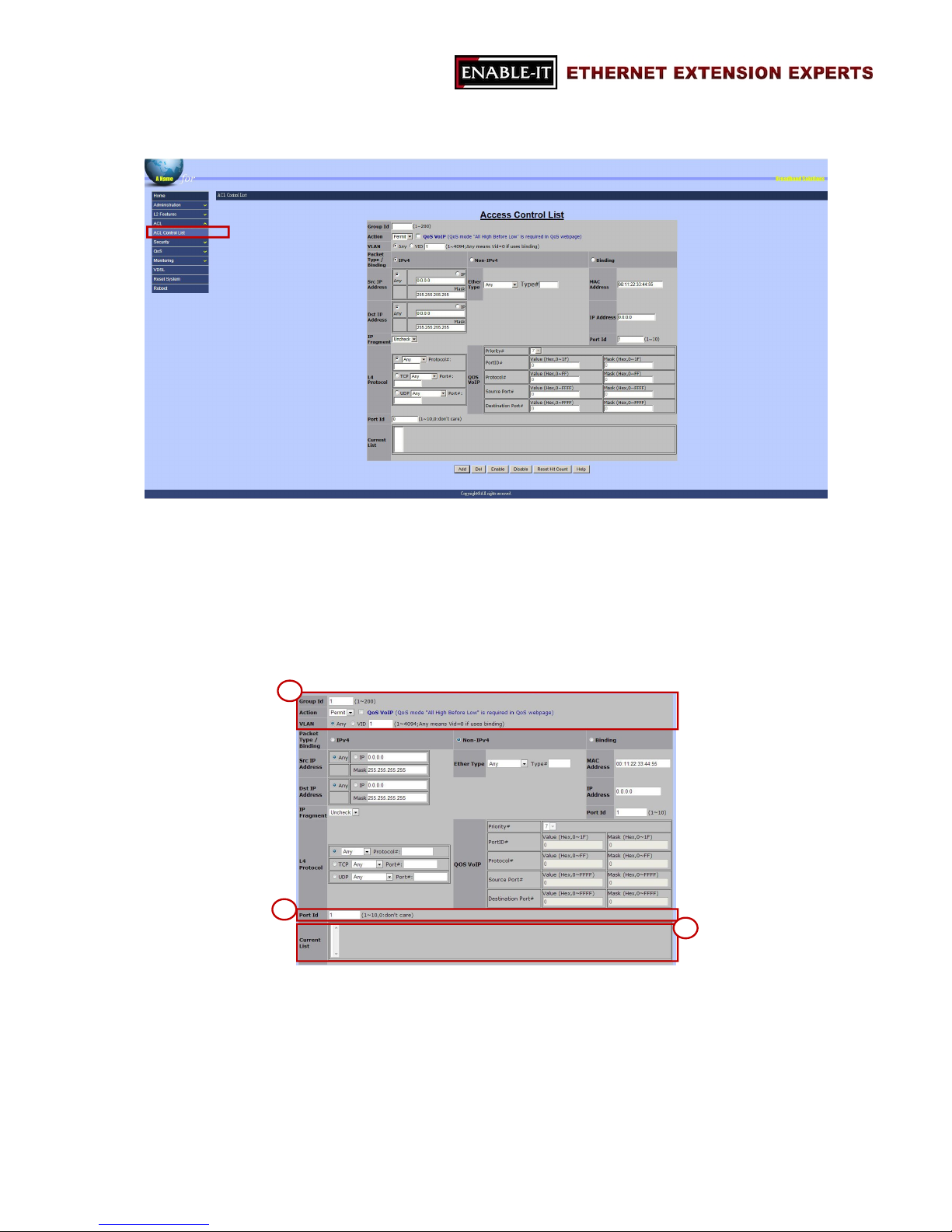
3.3 ACL
Packets can be forwarded or dropped by ACL rules include IPv4 or non-IPv4. The
switch can be used to block packets by maintaining a table of packet fragments indexed
by source and destination IP address, protocol, and so on.
There are 2 main ACL rule types to setup: Packet Type (IPv4 and Non-IPv4) and Binding
(SIP-SMAC-Port).
Section 1:
Group ID: the ID of this Access Control List (1 ~ 200).
Action: Permit or Deny the access
VLAN: Any or VID (a specific VLAN ID)
1
2
3
Page 57
All Rights Reserved 1997 - 2015 Enable-IT, Inc. Page 57 of 119
Section 2:
Port ID: the target port of this access control list should be applied to. (0: don’t
care/1 ~ 10)
Section 3:
Current List: the current list of all access control lists.
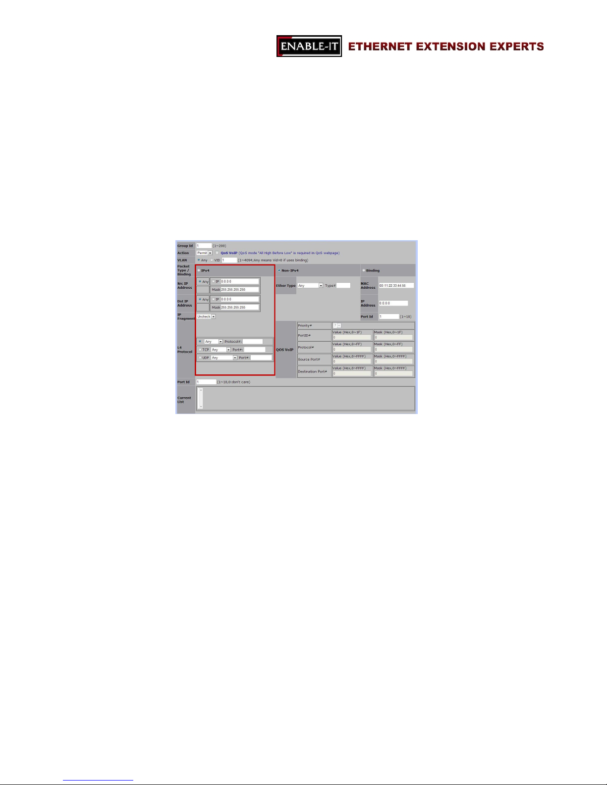
3.3.1 IPv4
Packet Type/ Binding
The option of “IPv4” is selected.
SRC IP Address
Options: Any or a specific IP address
The rule should be applied on these packets from which IP address or any IP
address.
DST IP Address
Options: Any or a specific IP address
The rule should be applied on these packets with an assigned destination IP
address or any IP address.
IP Fragment
Options: Uncheck or Check
To decide whether IP fragment should be checked or not.
L4 Protocol
Page 58
All Rights Reserved 1997 - 2015 Enable-IT, Inc. Page 58 of 119
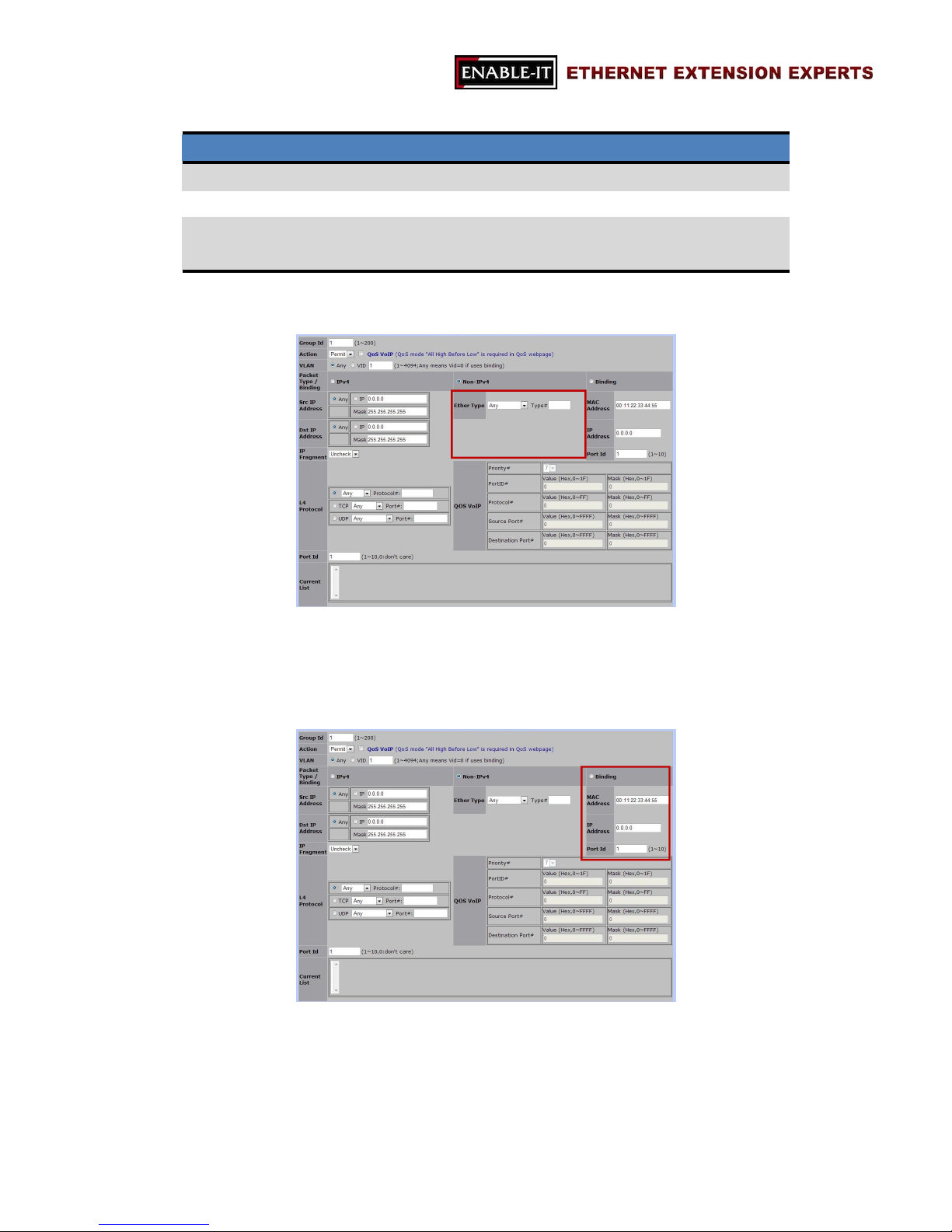
Options are as the following table
L4 Protocol Type Options Data
Any Any, ICMP, or IGMP Protocol No.
TCP Any, FTP, or HTTP Port No.
UDP Any, DHCP, TFTP,
NetBIOS
Port No.
3.3.2 Non-IPv4
Ether Type
Options: Any, ARP, or IPX
3.3.3 Binding
MAC Address
IP Address
Port ID (1 ~ 10)
Page 59
All Rights Reserved 1997 - 2015 Enable-IT, Inc. Page 59 of 119
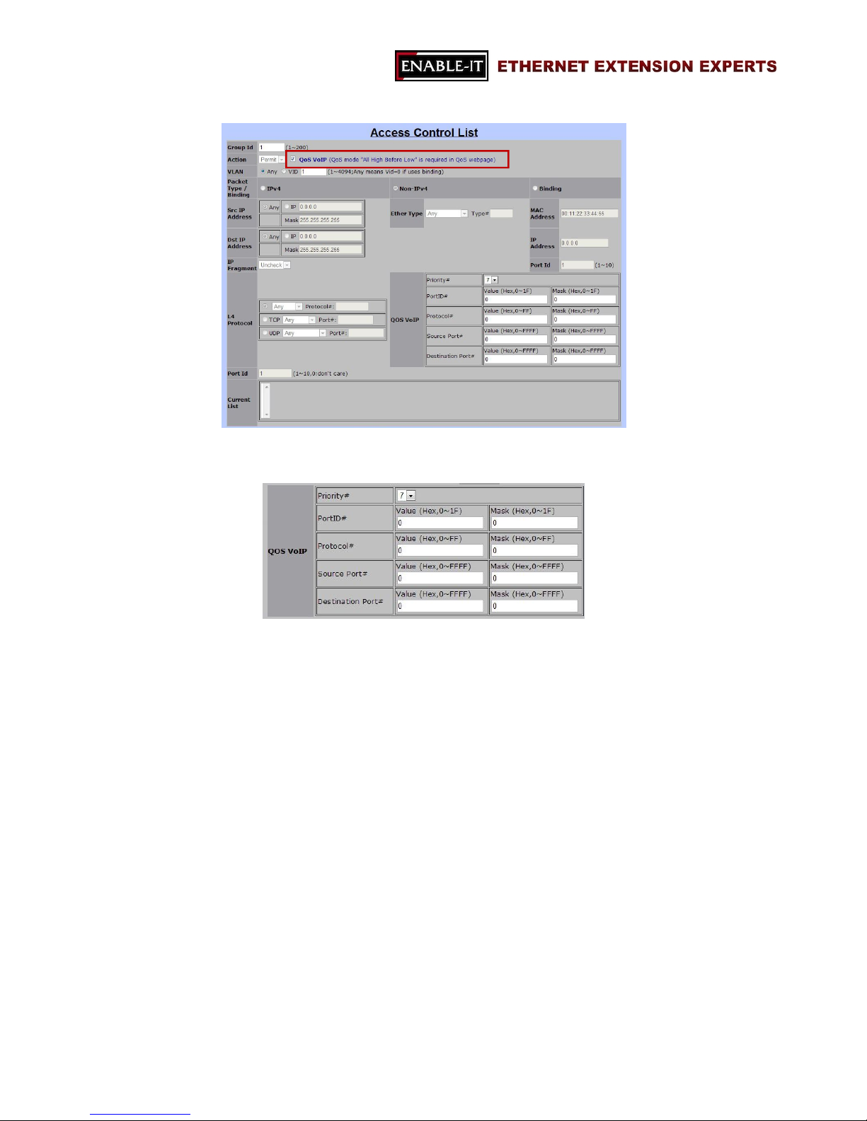
If the checkbox of QoS VoIP is selected, the following information should be provided.
QoS VoIP:
Priority
The priority of QoS VoIP
Options: 0 ~ 7
Port ID
Value
Mask
Protocol
Value
Mask
Source Port
Value
Mask
Destination Port
Value
Mask
Note: all values are in HEX format.
Page 60
All Rights Reserved 1997 - 2015 Enable-IT, Inc. Page 60 of 119
3.4 Security
“Security” section allows users to enhance the security level of this 8950 Gigabit IP
DSLAM. It includes the following functions:
Security Manager
MAC Limit
802.1x Configuration
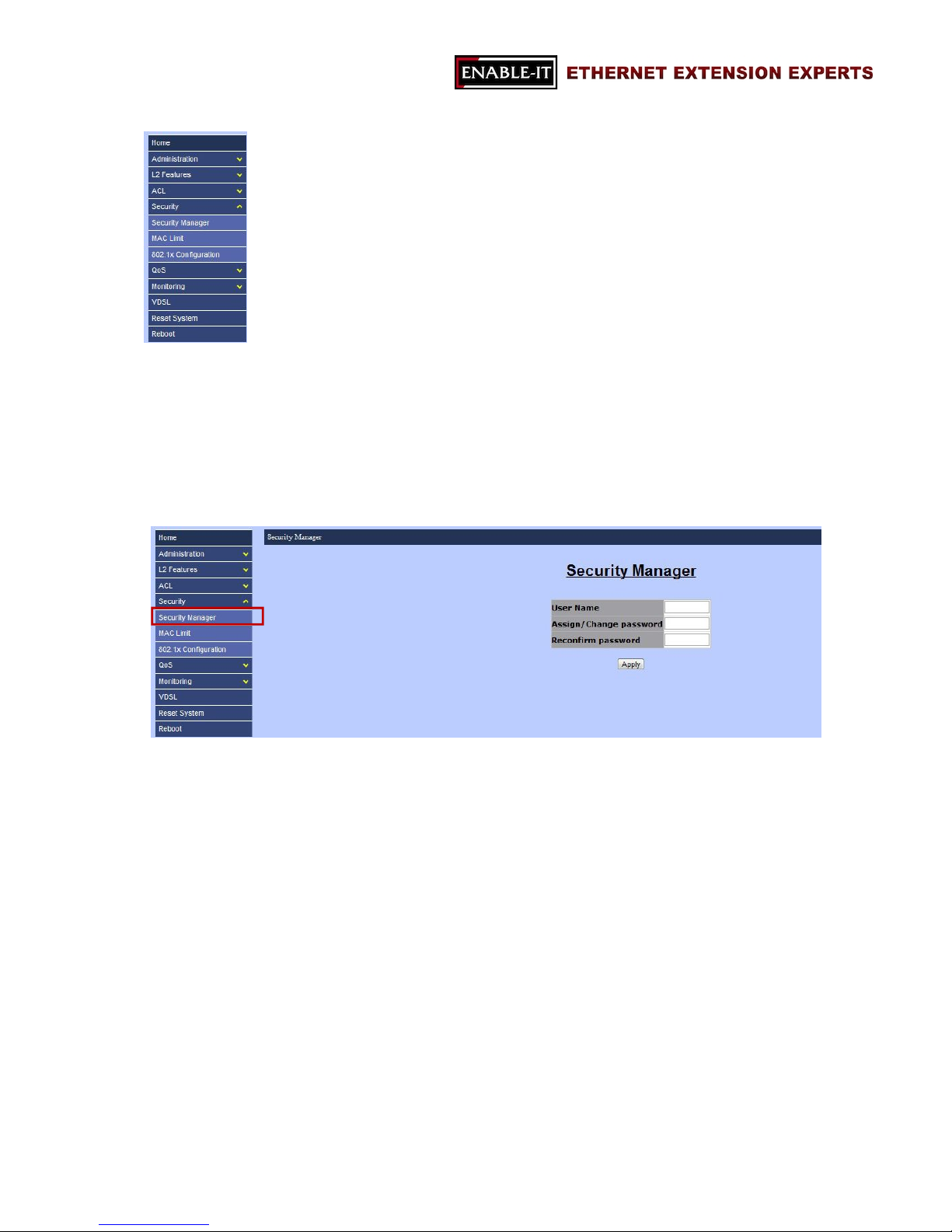
3.4.1 Security Manager
“Security Manager” allows users to change the user name and password for login
purpose. Only one set of user name and password is stored in the Switch. The
followings are the necessary information for this section.
User Name
Assign/Change Password
Reconfirm Password
Note: the default user name and password are “admin” and “admin”.
Page 61
All Rights Reserved 1997 - 2015 Enable-IT, Inc. Page 61 of 119
3.4.2 MAC Limit
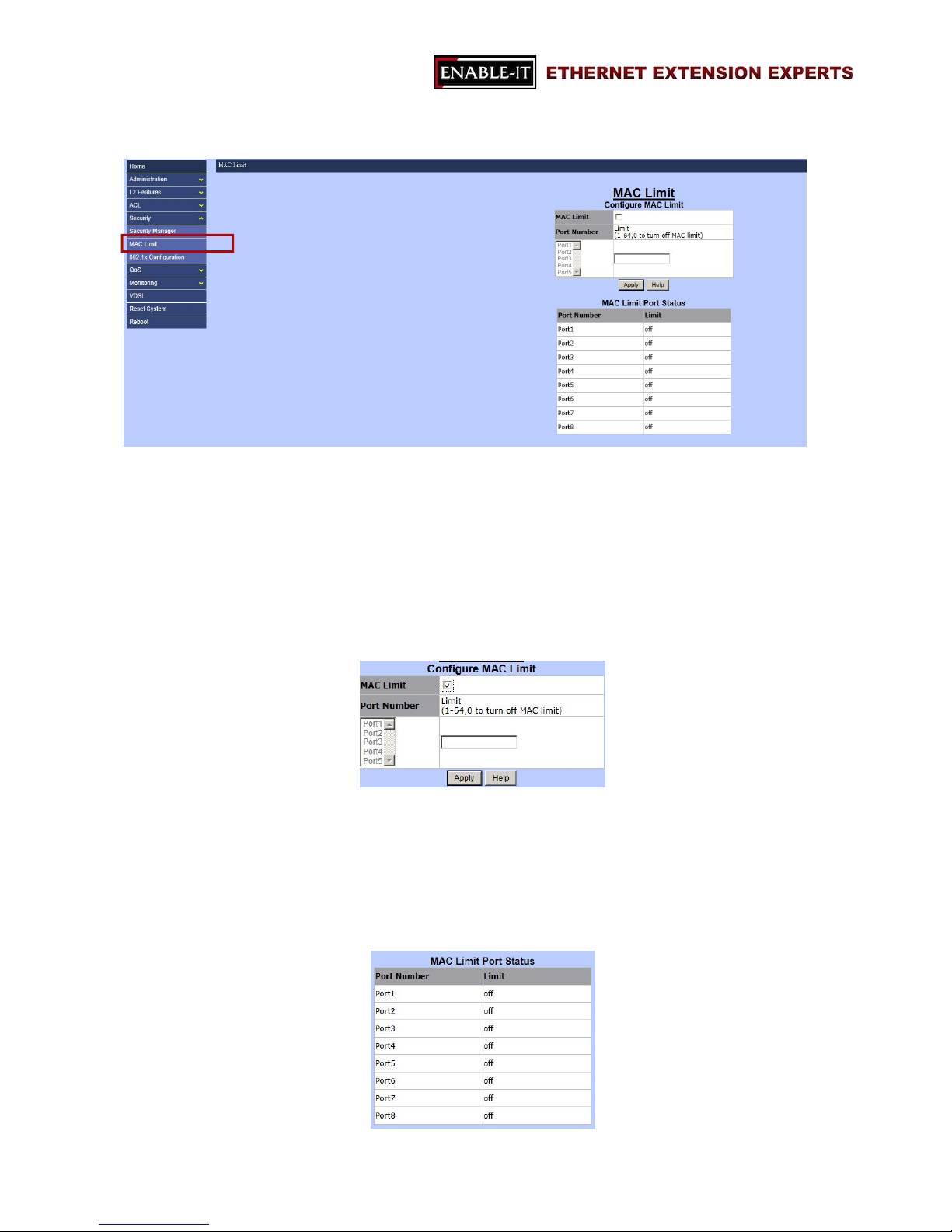
MAC limit allows users to set a maximum number of MAC addresses to be stored in the
MAC address table. The MAC addresses chosen to be stored in MAC address table is
the result of first-come-first-save policy. Once a MAC address is stored in the MAC
address table, it stays in until it is aged out. When an “opening” is available, the switch
stored the first new MAC address it sees in that opening. All packets from MAC
addresses not in the MAC address table should be blocked. Two sections are in MAC
Limit page:
- Configure MAC Limit
Users are able to setup MAC limit rules for each port in this section by providing the
information as the followings:
MAC Limit: enable or disable MAC limit function.
Limit: the maximum number of MAC addresses should be blocked.
- MAC Limit Port Status
Page 62
All Rights Reserved 1997 - 2015 Enable-IT, Inc. Page 62 of 119
This section allows users to review the status of ports and MAC limits.
3.4.3 802.1x Configuration
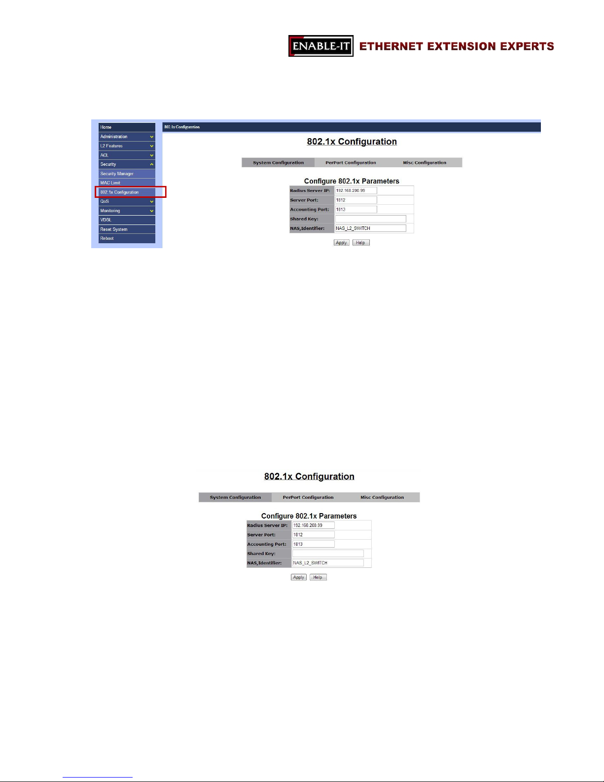
802.1x makes use of the physical access characteristics of IEEE 802 LAN infrastructures
in order to provide a means of authenticating and authorizing devices attached to a LAN
port that has point-to-point connection characteristics, and of preventing access to that
port in cases in which the authentication and authorization process fails.
Note: The default 802.1x setup is disabled, hence, users will not be able to see “802.1x
Configuration” page as showed above. To enable 802.1x, go to “Administration
Switch settingMisc Configs” page to enable the 802.1x protocol field. After enable
the function, the 802.1x configuration page will be shown up.
Three sections are in 802.1x configuration function:
- System Configuration
Radius Server IP: the IP address of the authentication server.
Server Port: the UDP port number used by the authentication server to
authenticate (default: 1812).
Accounting Port: the UDP port number used by the authentication server to
retrieve accounting information (default: 1813).
Shared Key: the password between the switch and the authentication server.
NAS, Identifier: the name of this switch.
Page 63
All Rights Reserved 1997 - 2015 Enable-IT, Inc. Page 63 of 119
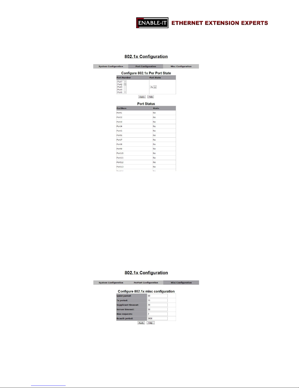
- PerPort Configuration
“PerPort Configuration” allows users to setup the authorization mode of 802.1x for each
port and review the authorization status of each port.
The 8950 Gigabit IP DSLAM allows users to setup four authorization modes:
FU: force the specific port to be unauthorized.
FA: force the specific port to be authorized.
AU: the state of the selected port was determined by the outcome of the
authentication.
NO: the selected port didn’t support 802.1x function.
- Misc Configuration
“Misc Configuratioin” page allows users to change miscellaneous setups of 802.1x
function.
Quiet Period: Used to define periods of time during which it will not attempt to
Page 64

All Rights Reserved 1997 - 2015 Enable-IT, Inc. Page 64 of 119
acquire a supplicant (default time: 60 seconds).
Tx Period: Used to determine when an EAPOL PDU is to be transmitted (Default
value is 30 seconds).
Supplicant Timeout: Used to determine timeout conditions in the exchanges
between the supplicant and authentication server (default value: 30 seconds).
Server Timeout: Used to determine timeout conditions in the exchanges between
the authenticator and authentication server (default value: 30 seconds).
ReAuthMax: Used to determine the number of re-authentication attempts that are
permitted before the specific port becomes unauthorized (default value: 2 times).
Reauth Period: Used to determine a nonzero number of seconds between periodic
re-authentication of the supplications (default value: 3600 seconds).
Page 65
All Rights Reserved 1997 - 2015 Enable-IT, Inc. Page 65 of 119
3.5 QoS
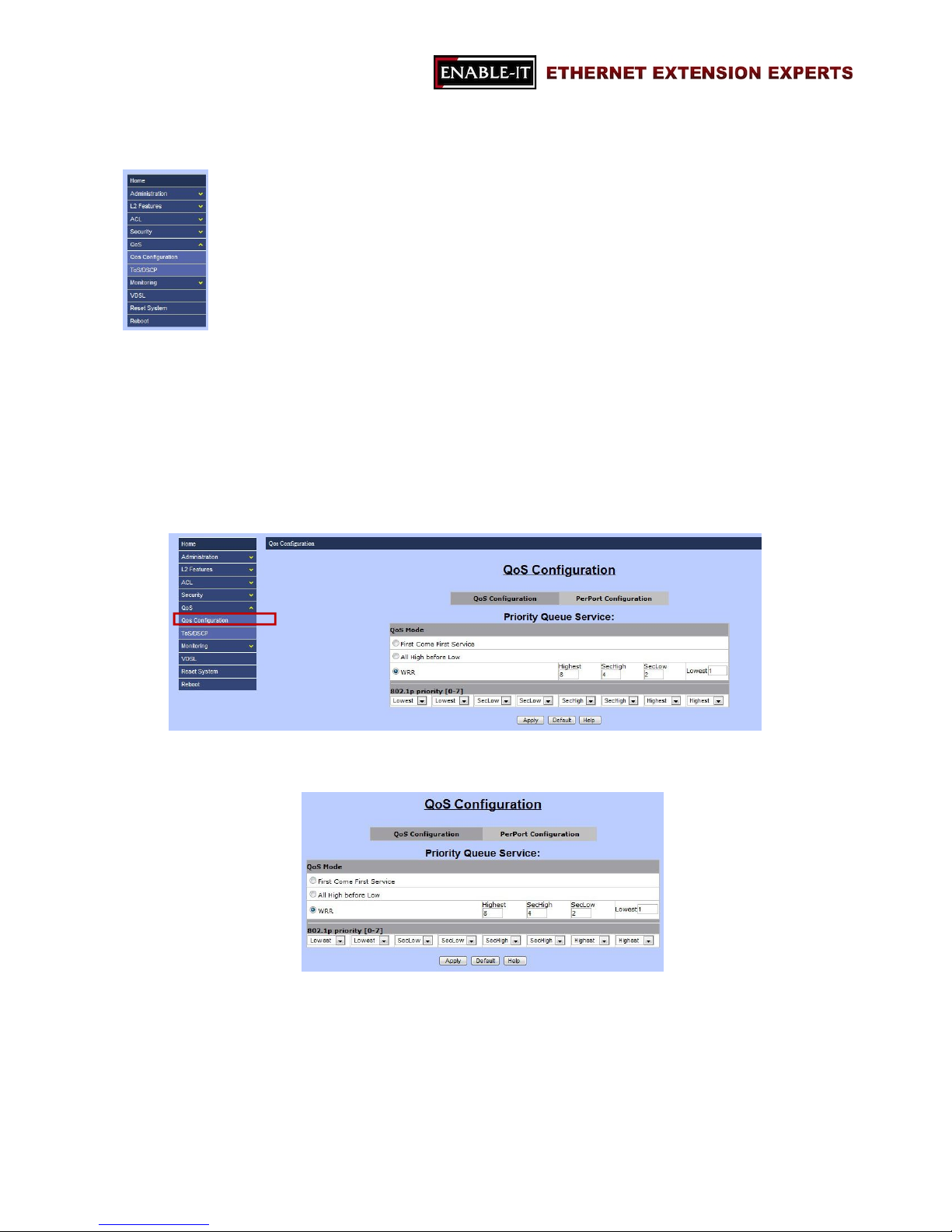
This switch provides quality of service (QoS) to prioritize the packet forwarding when
traffic congestion happens. This switch supports two QoS functions: port-based
(4-level output queue) and 802.1p (8-level priority to 4-level queue mapping). In
addition, Strict and weight Round Robin (WRR) QoS modes are supported.
3.5.1 QoS Configuration
“QoS Configuration” page includes two sections as the followings:
- QoS Configuration
Three QoS modes are supported in this switch:
First Come First Service
The sequence of packets sent is depending on arrive orders. This mode
can be regarded as QoS is disabled.
All High before Low
The high priority packets sent before low priority packets.
Page 66
All Rights Reserved 1997 - 2015 Enable-IT, Inc. Page 66 of 119
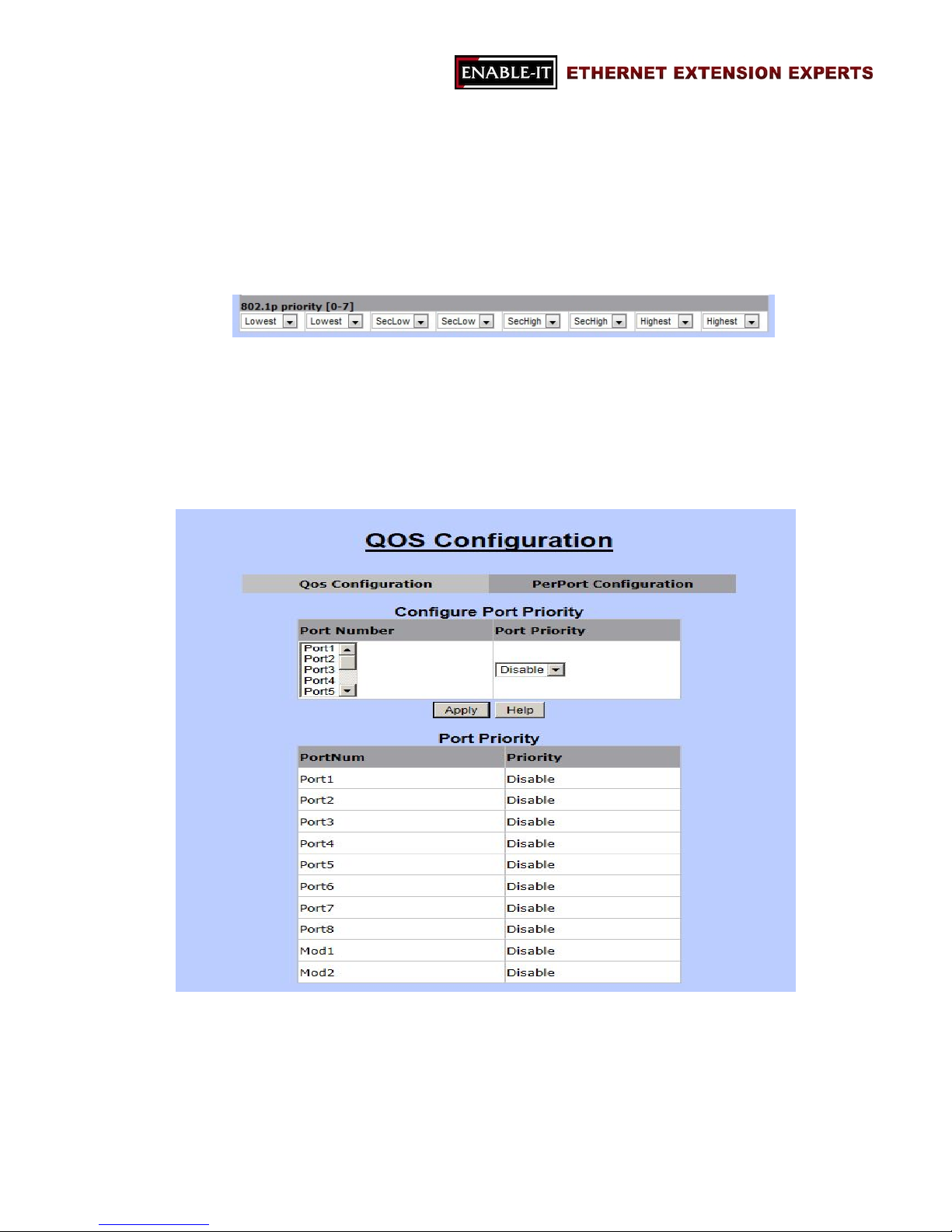
WRR
Weighted Round Robin. Select the preference given to packets in the
switch's high-priority queue. These options represent the number of
higher priority packets sent before one lower priority packet is sent.
For example, 8 Highest:4 second-high means that the switch sends 8
highest-priority packets before sending 4 second-high priority packets.
802.1p priority
The switch supports 802.1p priority queues with 4 priority levels (Highest,
Second-High, Second-Low, and Lowest). This section is for setting up the
maps of priority queues and priority levels.
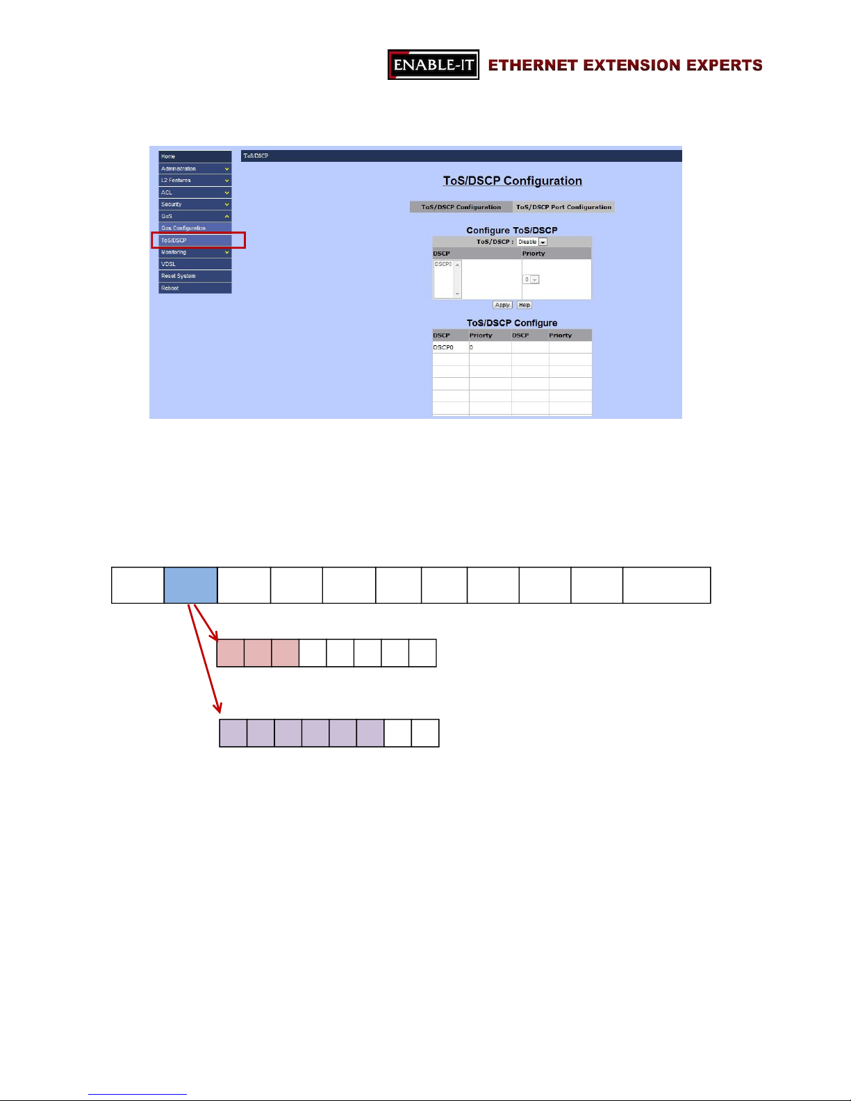
- PerPort Configuration
“PerPort Configuration” section allows users to setup the priority level for each port.
Users are able to setup QoS algorithm with Port-Based algorithm in this page.
Port Priority:
Options: Disable, 0 ~ 7.
Page 67
All Rights Reserved 1997 - 2015 Enable-IT, Inc. Page 67 of 119
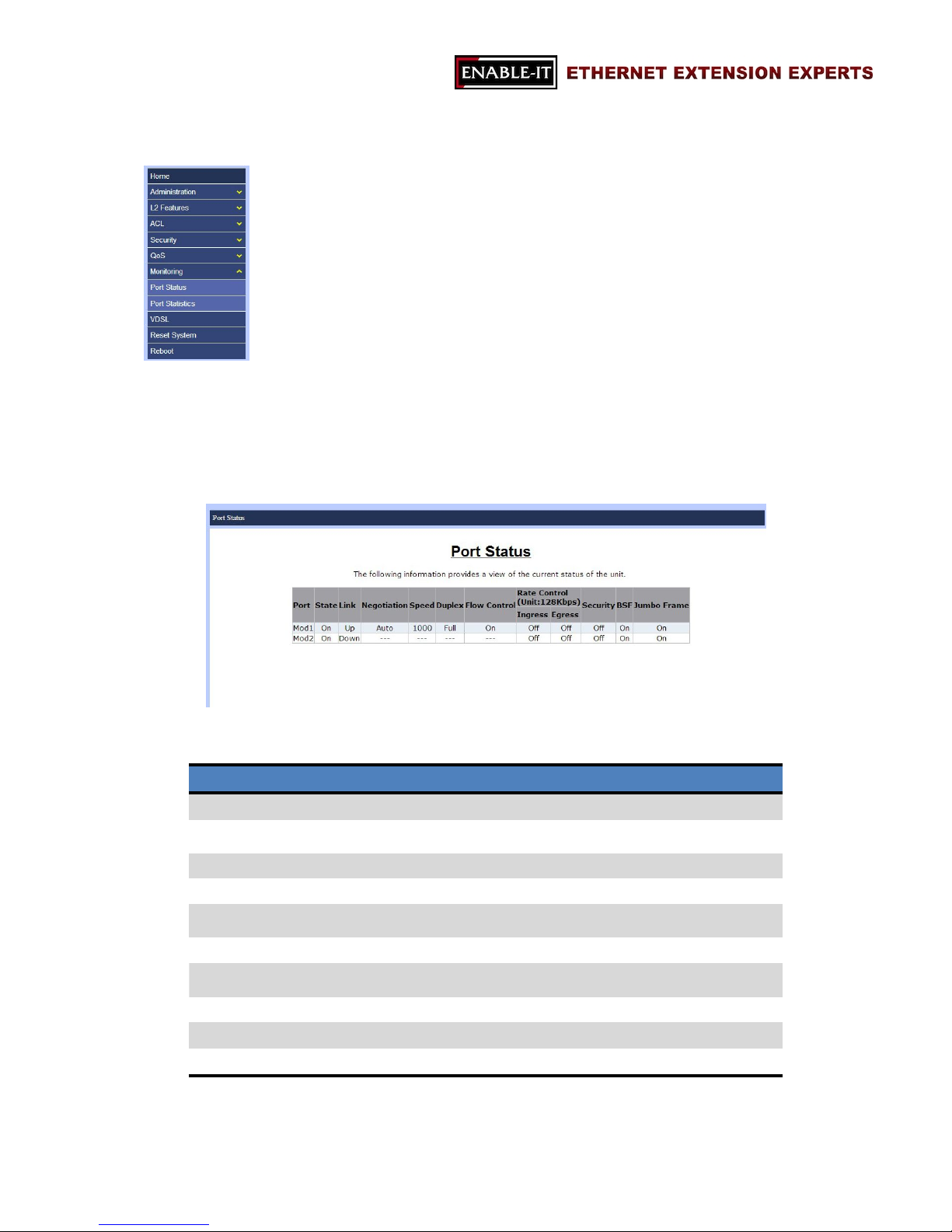
3.5.2 ToS/DSCP
“ToS/DSCP” page is where users can set up priority algorithm for each queue and
packets. In IPv4 packet header, there is a ToS byte. “ToS” stands for “Type of
Service”, and ToS algorithm uses first 3 bits for priority level. However, for DSCP
algorithm, it will take first 6 bits for priority level.
DSCP
IP PRECEDENCE
VERSIONToS
1 Byte
LENIDOffset
TTL
PROTOIP SA
FCS
IP DA
DATA
Page 68
All Rights Reserved 1997 - 2015 Enable-IT, Inc. Page 68 of 119
3.6 Monitoring
“Monitoring” function is for users to review current status and statistics of each port
(Port1 ~ Port8, Mod1 and Mod2).
3.6.1 Port Status
“Port Status” displays current status of linked ports. This page is for review only. The
information will be showed are as the followings.
Item Data
Port Port No.
State
On
(Only linked port will be showed)
Link Up / Down
Negotiation Auto / Force
Speed
10 / 100 Mbps (Port1 ~ Port24)
10 / 100 / 1000 Mbps (Mod1 ~ Mod2)
Duplex Full / Half
Rate Control
(both Ingress and Egress)
On / Off
Security On / Off
BSF On / Off
Jumbo Frame On / Off
Page 69
All Rights Reserved 1997 - 2015 Enable-IT, Inc. Page 69 of 119
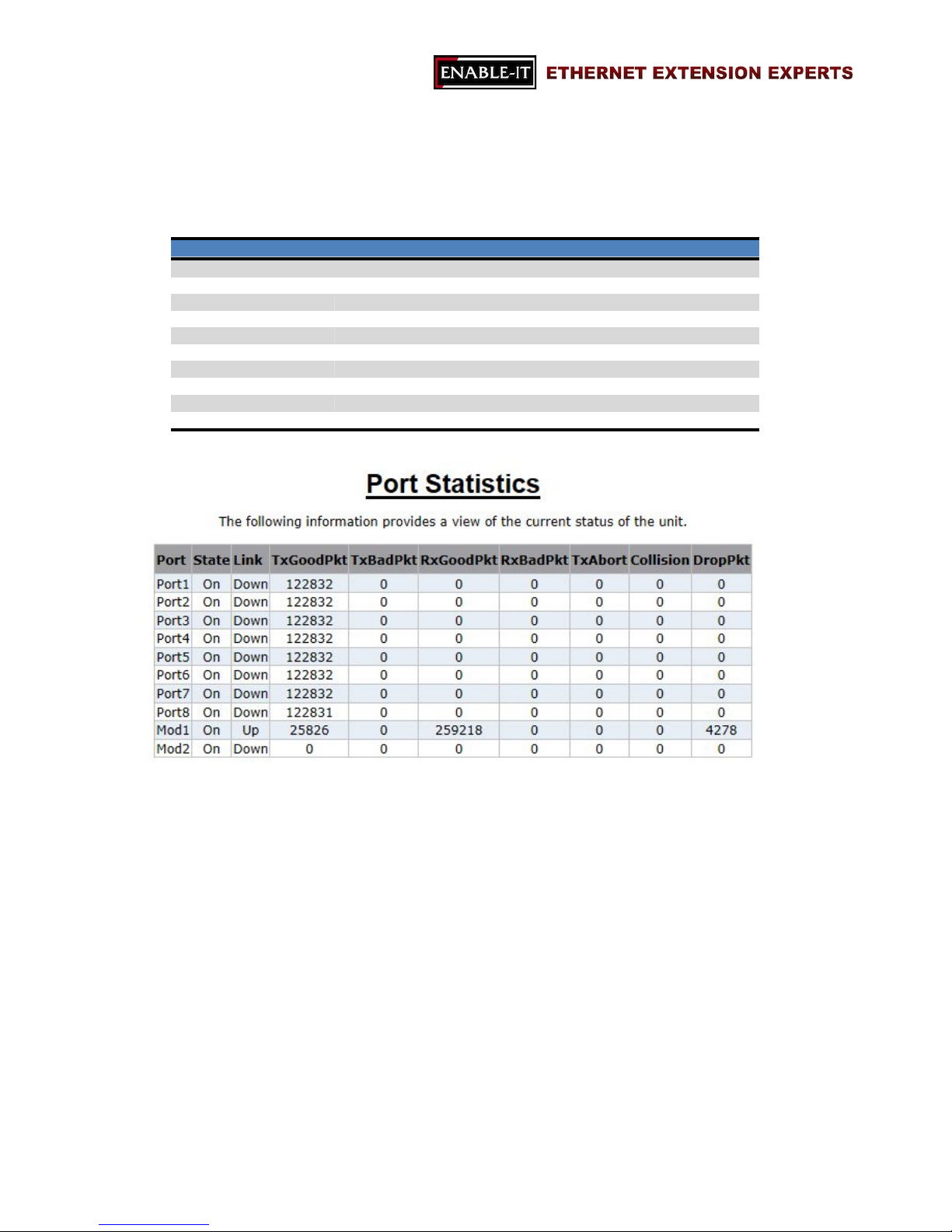
3.6.2 Port Statistics
“Port Statistics” allows users to review the statistics data of each port with the following
details.
Item Data
Port Port No
State
On / Down
Link
On / Down
TxGoodPkt
The total bytes of good packets which were transmitted
TxBadPkt
The total bytes of bad packets which were transmitted
RxGoodPkt
The total bytes of good packets which were received
RxBadPkt
The total bytes of bad packets which were received
TxAbort
The total bytes of packets which were aborted.
Collision
Collision
DropPkt The total bytes of packets dropped
Page 70
All Rights Reserved 1997 - 2015 Enable-IT, Inc. Page 70 of 119
3.7 VDSL
“VDSL” page is where users are able to setup and review VDSL profiles. Two sections
are included in VDSL page:
Configuration
Profile Table
3.7.1 Configuration
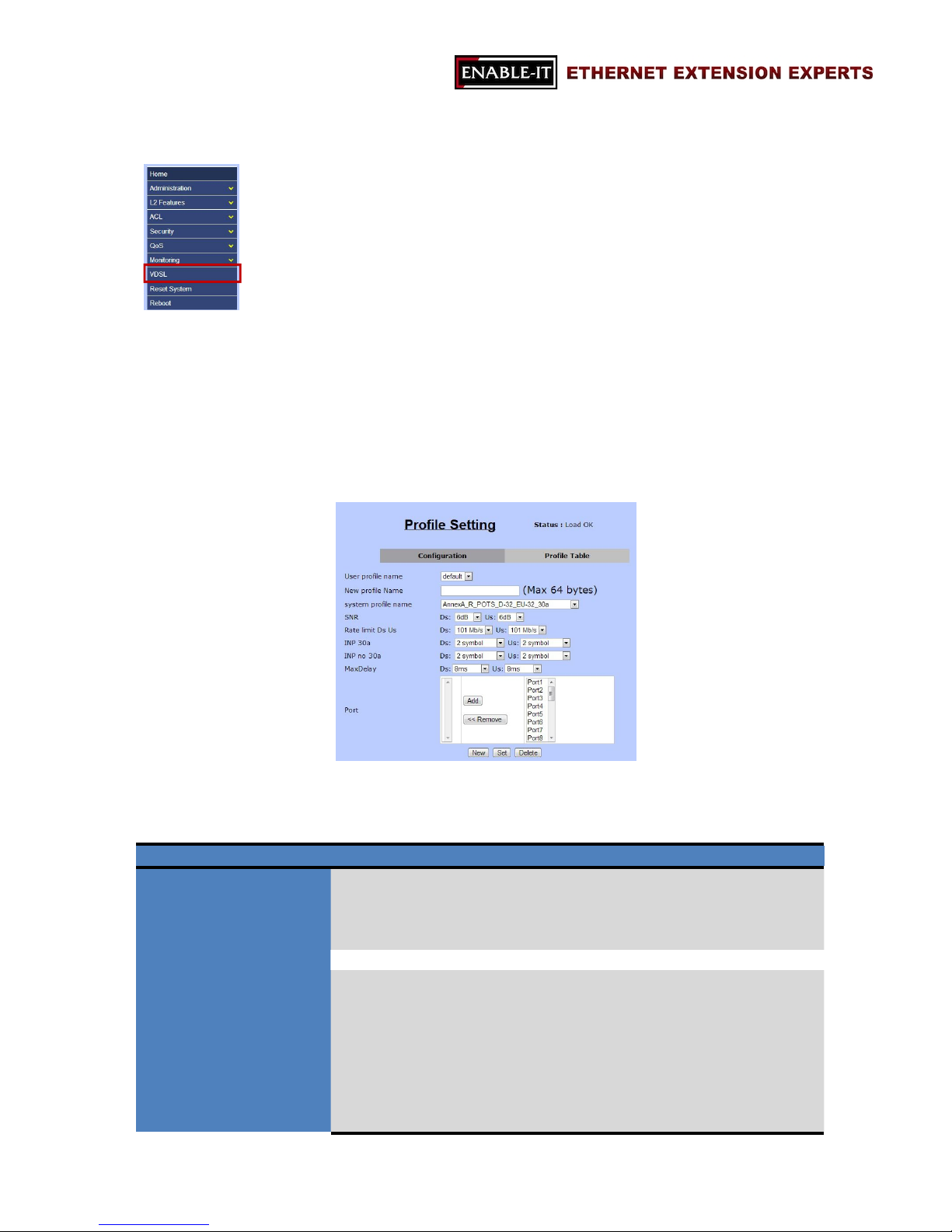
“Configuration” is where users set up VDSL profiles and store these profiles into the
system. The followings are the details of each VDSL profile users can set up.
Item Description
User Profile Name
The name of user-defined profile.
Note: There are 21 pre-defined profiles. These names are
not changeable. Users are allowed to save new profiles with
“New” button.
New Profile Name
New profile name (up to 64 chars)
System Profile Name
This option is for setting up VDSL band profile. Different
profile results in different connection status of data rate and
distance.
1. AnnexA_R_POTS_D-64_EU-64_30a
2. AnnexA_R_POTS_D-32_EU-32_17a
3. AnnexA_R_POTS_D-32_EU-32_12b
4. AnnexA_R_POTS_D-32_EU-32_12a
5. AnnexA_R_POTS_D-32_EU-32_8a
Page 71

All Rights Reserved 1997 - 2015 Enable-IT, Inc. Page 71 of 119
6. AnnexA_R_POTS_D-32_EU-32_8b
7. AnnexA_R_POTS_D-32_EU-32_8c
8. AnnexA_R_POTS_D-32_EU-32_8d
9. AnnexA_R_POTS_D-32_EU-64_30a_NUS0
10. AnnexA_R_POTS_D-32_EU-64_17a
11. AnnexB_B7-1_997-M1c-A-7
12. AnnexB_B7-2_997-M1x-M-8
13. AnnexB_B7-3_997-M1x-M
14. AnnexB_B7-4_997-M2x-M-8
15. AnnexB_B7-5_997-M2x-A
16. AnnexB_B7-6_997-M2x-M
17. AnnexB_B7-9_997E17-M2x-A
18. AnnexB_B7-10_997E30-M2x-NUS0
19. AnnexB_B8-1_998-M1x-A
20. AnnexB_B8-1_998-M1x-B
21. AnnexB_B8-4_998-M2x-A
22. AnnexB_B8-5_998-M2x-M
23. AnnexB_B8-6_998-M2x-B
24. AnnexB_B8-8_998E17-M2x-NUS0
25. AnnexB_B8-9_998E17-M2x-NUS0-M
26. AnnexB_B8-10_998ADE17-M2x-NUS0-M
27. AnnexB_B8-11_998ADE17-M2x-A
28. AnnexB_B8-12_998ADE17-M2x-B
29. AnnexB_B8-13_998E30-M2x-NUS0
30. AnnexB_B8-14_998E30-M2x-NUS0-M
31. AnnexB_B8-15-998ADE30-M2x-NUS0-M
32. AnnexB_B8-16-998ADE30-M2x-NUS0-A
33. AnnexC_POTS_25-138_b
34. AnnexC_POTS_25-276_b
35. AnnexC_TCM_ISDN
SNR
SNR values for both downstream and upstream (6dB ~ 24dB)
Rate Limit Ds Us
The data rates for both downstream and upstream
INP 30a
INP levels for VDSL2 profile 30a for both downstream and
upstream
INP no 30a
INP levels for other VDSL2 profiles (8a, 8b, 8c, 8d, 12a, 12b,
and 17a) for both downstream and upstream
Max Delay
The maximum delay time for both downstream and upstream
Options: No limit, No delay, 1ms ~ 63ms
Port For assigning which ports should be applied the profile to.
Page 72
All Rights Reserved 1997 - 2015 Enable-IT, Inc. Page 72 of 119
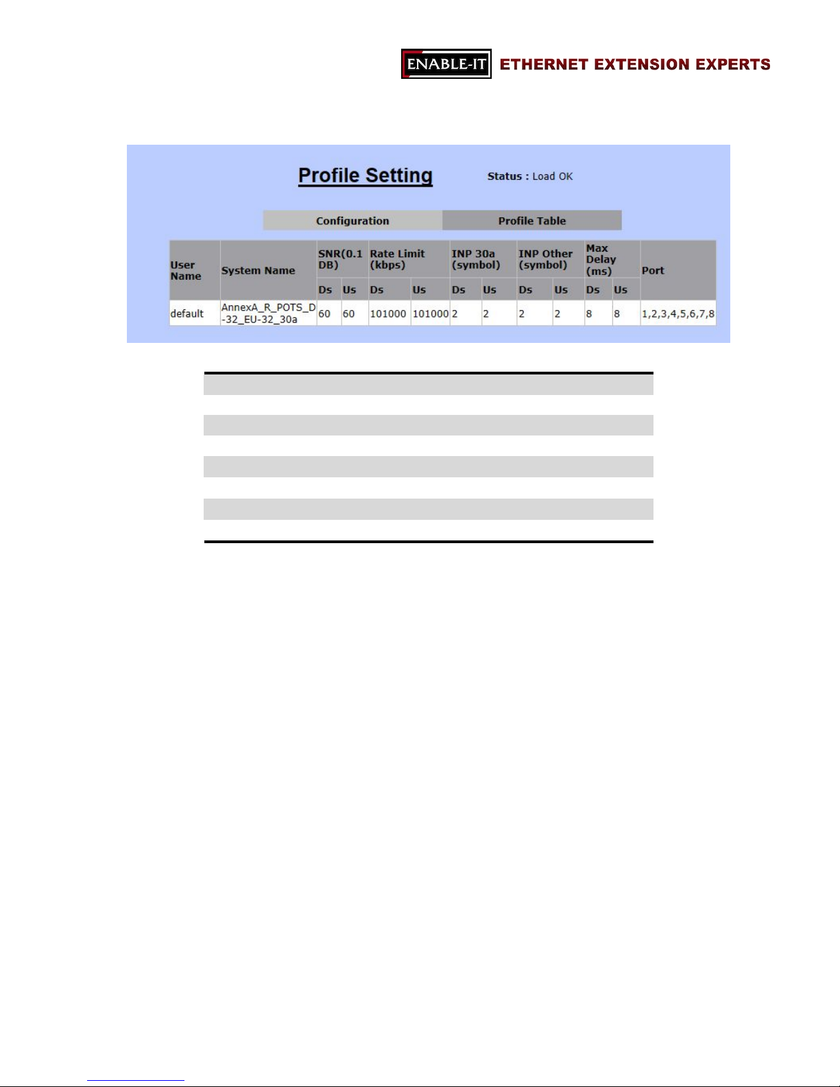
3.7.2 Profile Table
“Profile Table” is for users to review the details of existing profiles in the following details.
User Name The profile name
System Name VDSL2 Band profile
SNR (Ds / Us) SNR value
Rate Limit (Ds / Us)
The data rate
INP 30a (Ds / Us) INP level for VDSL2 profile 30a
INP Other (Ds / Us)
INP level for the other VDSL2 profiles
Max Delay Maximum delay
Port The port members of this profile
Page 73
All Rights Reserved 1997 - 2015 Enable-IT, Inc. Page 73 of 119
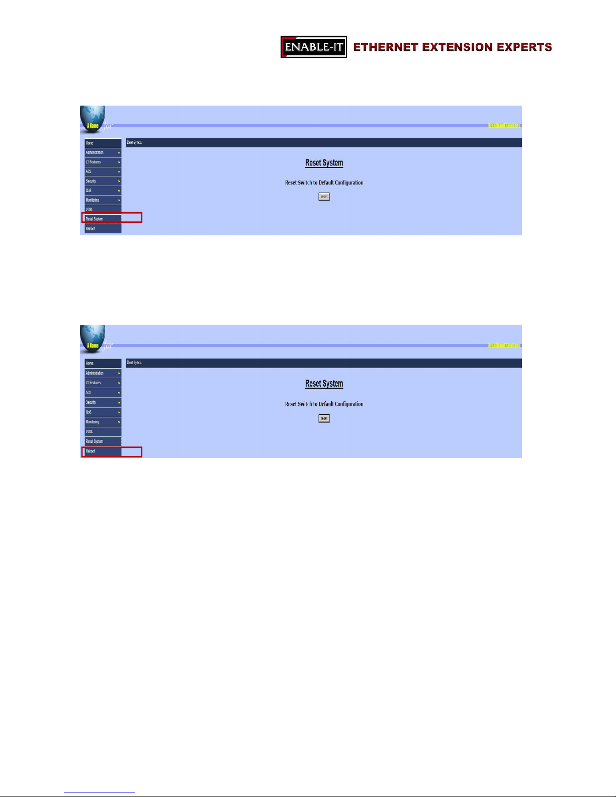
3.8 Reset System
“Reset System” is for restoring all configurations back to the default factory
configurations. All the settings will be changed back to the original state.
3.9 Reboot
“Reboot” allows users to reboot the switch without turning off the power.
Page 74
All Rights Reserved 1997 - 2015 Enable-IT, Inc. Page 74 of 119
Chapter 4 Configuration via Console
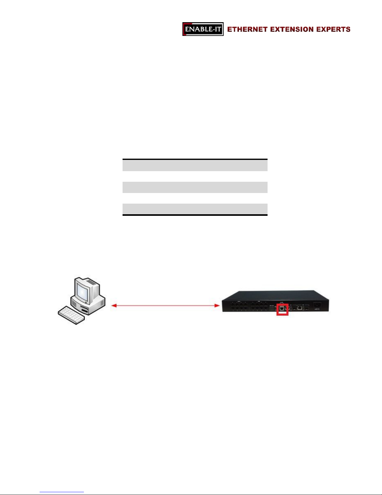
The 8950 Gigabit IP DSLAM support Command Line Interface for users to access the
switch without opening any web browser. It is easily accessible for users with any
terminal emulation program, such as, Hyperterminal, or teraterm, etc.
The default setting of the serial port to connect to the switch is as the following.
Baud Rate 115200
Data Bit 8
Parity None
Stop Bit 1
Flow Control None
Page 75
All Rights Reserved 1997 - 2015 Enable-IT, Inc. Page 75 of 119
4.1 Login into the Console
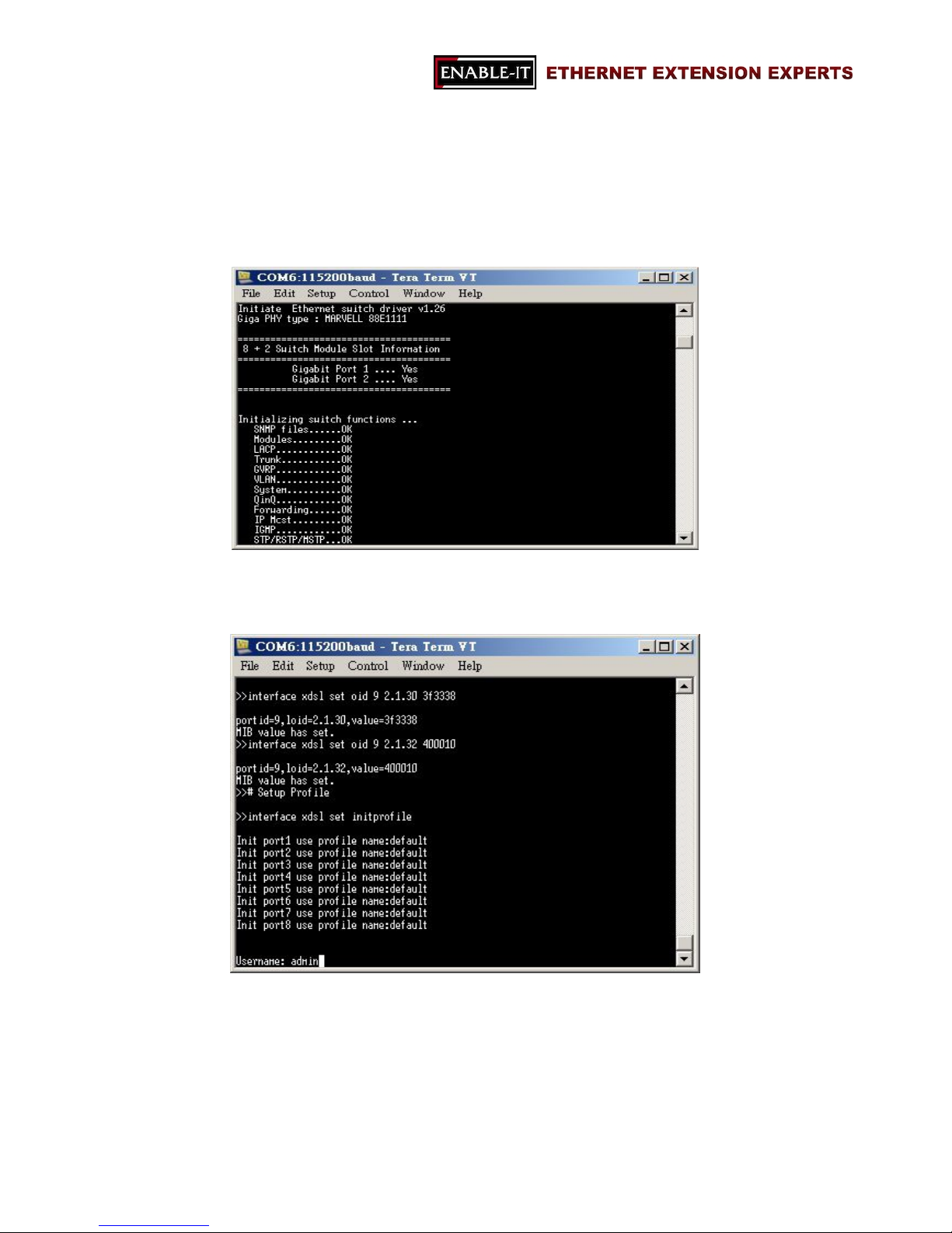
After connecting the switch with PC or laptop together, users are able to login with a
terminal emulation program, such as, Hyperterminal, etc. Users should be able to see
the following image while the switch is booting.
When the booting process is completed, users will notice a login request as the following
image.
The default user name and password are “admin” and “admin”. Once the correct user
name and password are provided, users should be able to login in and see “Switch#”
showed.
Page 76
All Rights Reserved 1997 - 2015 Enable-IT, Inc. Page 76 of 119
4.2 General Information of Commands
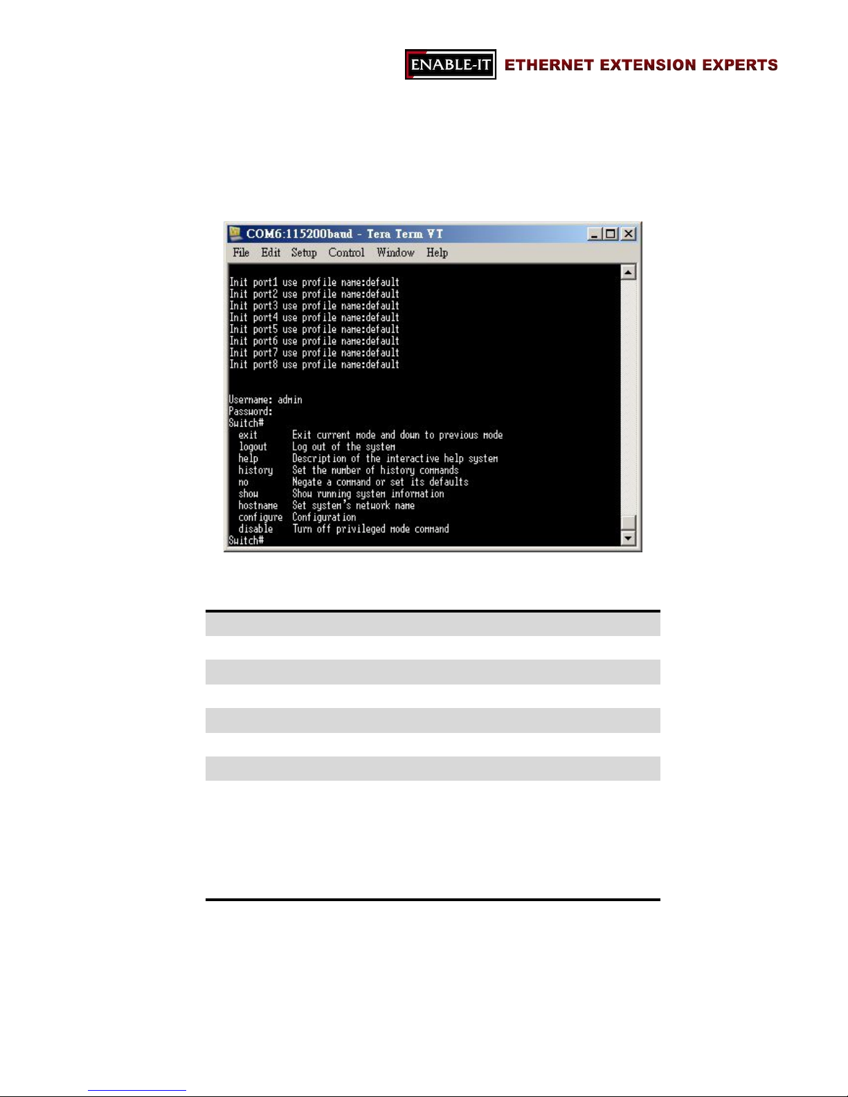
Users are able to review help information with “?” command.
Nine major commands are provided in the root mode.
exit Exit current mode and move to previous mode
logout Log out the system
help Show the description of a command
history Set the number of history commands
no Negate a command or set its defaults
show Show information
configure Configuration
disable
Turn off privileged mode command
- This will turn off the privilege of setting out
system configurations.
- “enable” will be showed if user disables the
privilege
Page 77
All Rights Reserved 1997 - 2015 Enable-IT, Inc. Page 77 of 119
4.3 Configuration
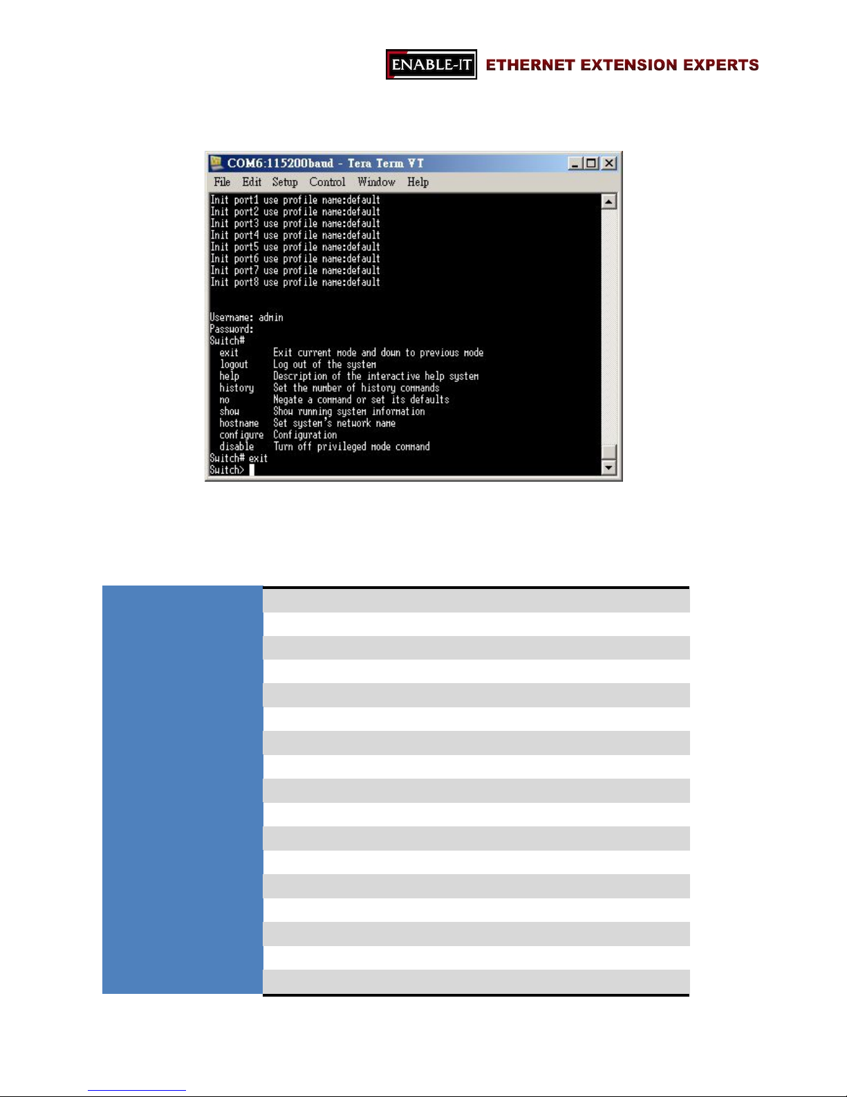
In order to go to configuration mode, users should key in “config” in “Switch#” and enter.
Then, users are able to configure the settings of 8950 Gigabit IP DSLAM.
The followings are the available configurations of the switch.
exit Exit current mode and change to the previous mode
logout Log out the system
help Show the description of a command
history Set the number of history commands
no Negate a command or set its defaults
show Show running system information
hostname Set up the switch’s network name
disable Turn off privileged mode (disable configuration mode)
password Password information
timeout Set up the timeout for the current CLI
syslog-server Set up the information of syslog server
broadcast Set up Broadcast storm filter mode
collision-retry Set up the settings of collision-retry function
mac-age-time Enable MAC address age-out function
mac-hash Set up MAC hash algorithm
mirror-port Port monitoring information
qos QoS information
Page 78

All Rights Reserved 1997 - 2015 Enable-IT, Inc. Page 78 of 119
tosport ToS/DSCP port status information
tosdscp ToS/DSCP information
clear Clear values in destination protocol
mac-address-table MAC address table information
smac-address-tableMAC address table information
filter Filter destination MAC address information
mac-limit MAC limit
port Port information
boot Reboot the switch
copy Copy configurations
dhcp DHCP information
erase Erase configuration
ip IP information
ping Send ICMP ECHO_REQUEST to network hosts
dhcp-option82 Enable DHCP option 82 feature
dhcp-relay Enable DHCP relay feature
qinq QinQ information
trunk Trunking information
vlan VLAN information
dot1x 802.1x information
radius-server Radius server information
garp GARP information
gvrp GVRP information
igmp IGMP information
lacp LACP information
snmp SNMP information
sntp Start SNTP service
spanning-tree Spanning Tree Protocol
acl ACL information
enable Enable privileged command mode
bind Enable SIP/SMAC binding
dslcli Run DSL CLI
interface Commands for interfaces
profiles Commands for profiles
util Commands for VDSL utility
Page 79

All Rights Reserved 1997 - 2015 Enable-IT, Inc. Page 79 of 119
4.4 Command Descriptions
4.4.1 System Commands
show running-config
Show the running configuration of the switch.
copy running-config startup-config
Backup the configurations of the switch.
erase startup-config
Reset to default factory configurations at the following boot time.
clear arp [ip-address]
Clear entries in the ARP cache in the selected IP address.
show arp
Show IP ARP translation table.
ping ip-addr [<1…999>]
Send ICMP ECHO_REQUEST to the selected IP address.
<1…999>: the number of repetitions. If there is no value in this area, it will
continuously ping until users press <Ctrl>+C to stop.
no per-vlan-flooding-portmask
Enable or disable per VLAN default flooding port mask.
per-vlan-flooding-portmask <unicast | multicast> <vlan-id> <port-list>
Set unicast or multicast per VLAN default flooding port mask.
show per-vlan-flooding-portmask
Display unicast and multicast per VLAN default flooding port mask table.
4.4.2 Switch Static Configuration
Page 80

All Rights Reserved 1997 - 2015 Enable-IT, Inc. Page 80 of 119
port state <on | off> [<port-list>]
Turn on or turn off the port state.
<port-list>: specifies the ports to be turn on or off. If no <port-list> value, all ports
will be turn on or turn off.
port nego <force | auto > [<port-list>]
Set port negotiation mode.
<port-list>: specifies the ports to be set. If no value, all port will be set.
port speed <10 | 100 | 1000> <full | half> [<port-list>]
Set port speed (mbps) and duplex.
<port-list>: specifies the ports to be set. If no value, all port will be set.
port flow <enable | disable> <enable | disable> [<port-list>]
Enable or disable port flow control.
1st <enable | disable>: enables or disables flow control in full duplex mode.
2nd <enable | disable>: enables or disables flow control in half duplex mode.
<port-list>: specifies the ports to be set. If not entered, all ports are set.
port rate <ingress | egress> <0..8000> [<port-list>]
Set port effective ingress or egress rate.
<0...8000>: specifies the ingress or egress rate. (0…8000)
<port-list>: specifies the ports to be set. If not entered, all ports are set.
port security <on | off> [<port-list>]
Set port priority. When port security is on, the port will stop MAC address learning,
and forward only packets with MAC address in the static MAC address table.
<port-list> specifies the ports to be set. If not entered, all ports are set.
port protected group <1-2> <port-list>
Set protected port group member.
<port-list> specifies the group member ports.
Page 81

All Rights Reserved 1997 - 2015 Enable-IT, Inc. Page 81 of 119
port protected <port-list>
Set protected port list.
<port-list> specifies the protected port list.
port priority <disable | low | high> [<port-list>]
Set port priority.
<port-list> specifies the ports to be set. If not entered, all ports are set.
port jumboframe <enable | disable> [<port-list>]
Set port jumbo frame. When port jumbo frame is enable, the port forward jumbo
frame packet
<port-list> specifies the ports to be set. If not entered, all ports are set.
port interval <0-3600>:
While flooding CPU port at the speed of 4MB/s or larger, system will close relative
port. And system will open this port using this interval value.0 represents system will
never enable this after close it for flooding CPU.
show port status
Show port status, including port State, Link,
Trunking,VLAN,Negotiation,Speed,Duplex,Flow control, Rate
control ,Priority,Security,BSF control.
show port statistics <port-id>
Show port statistics, including TxGoodPkt, TxBadPkt, RxGoodPkt,
RxBadPkt,TxAbort, Collision, and DropPkt.
<port-id> specifies the port to be shown.
show port protection
Show protected port information.
Page 82

All Rights Reserved 1997 - 2015 Enable-IT, Inc. Page 82 of 119
4.4.3 Trunk Commands
show trunk
Show trunking information.
trunk add <trunk-id> <lacp | no-lacp> <port-list> <active-port-list>
Add a new trunk group.
<trunk-id> specifies the trunk group to be added.
<lacp> specifies the added trunk group to be LACP enabled.
<no-lacp> specifies the added trunk group to be LACP disabled.
<port-list> specifies the ports to be set.
<active-port-list> specifies the ports to be set to LACP active.
no trunk <trunk-id>
Delete an existing trunk group.
<trunk-id> specifies the trunk group to be deleted.
Page 83

All Rights Reserved 1997 - 2015 Enable-IT, Inc. Page 83 of 119
4.4.4 LACP Commands
[no] lacp
Enable/disable LACP.
lacp system-priority <1..65535>
Set LACP system priority.
Parameters:
<1..65535> specifies the LACP system priority.
no lacp system-priority
Set LACP system priority to the default value 32768.
show lacp status
Show LACP enable/disable status and system priority.
show lacp
Show LACP information.
show lacp agg <trunk-id>
Show LACP aggregator information.
<trunk-id> specifies the trunk group to be shown.
show lacp port <port-id>
Show LACP information by port.
<port-id> specifies the port to be shown.
NOTE: If VLAN group exist, all of the members of static trunk group must be in same
VLAN group.
Page 84

All Rights Reserved 1997 - 2015 Enable-IT, Inc. Page 84 of 119
4.4.5 VLAN Mode & Commands
VLAN Mode: Port based
Packets can go among only members of the same VLAN group. Note all unselected
ports are treated as belonging to another single VLAN. If the port-based VLAN enabled,
the VLAN-tagging is ignored.
VLAN Mode: 802.1Q
If a trunk group exists, you can see it (e.g. TRUNK1, TRUNK2…) after port 8. And, you
can configure it to be a member of the VLAN group. In the setting, port was set to
Untagged if devices underneath this port do not support VLAN-tagging. Thus the
switch can send untagged frames to this port. Consequently, device that do not support
VLAN-tagging or do not enable VLAN tagging could successfully fetch the incoming
frames and could communicate with device that transfers tagged frames, and vice versa.
Advanced 802.1Q VLAN Setting
Ingress filters configuration when a packet was received on a port, you can govern the
switch to drop it or not if it is an untagged packet. Furthermore, if the received packet is
tagged but not belonging to the same VALN group of the receiving port, you can also
control the switch to forward or drop the packet. The example below configures the
switch to drop the packets not belonging to the same VLAN group and forward the
packets not containing VLAN tags.
show vlan mode
Display the current VLAN mode.
vlan mode (disabled|port-based|dot1q)
Change VLAN mode.
(disabled|port-based|dot1q) specifies the VLAN mode.
NOTE: Change the VLAN mode for every time, user have to restart the switch for valid
value.
show vlan mode
Display the current VLAN mode.
Page 85

All Rights Reserved 1997 - 2015 Enable-IT, Inc. Page 85 of 119
vlan mode (disabled|port-based|dot1q)
Change VLAN mode.
Parameters:
(disabled|port-based|dot1q) specifies the VLAN mode.
NOTE: Change the VLAN mode for every time, user have to restart the switch for valid
value.
vlan add <1-4094> <NAME> <cpu-port|no-cpu-port> <LIST> [<LIST>]
Add or edit VLAN entry.
<1-4094> specifies the VLAN id or Group id (if port based VLAN mode)
<NAME> specifies the VLAN group name.
<cpu-port|no-cpu-port> specifies the CPU port belong this VLAN group.
1st <LIST> specifies the ports to be set to VLAN members.
2nd [<LIST>] specifies the ports to be set to tagged members. If not entered, all
members set to untagged.
e.g. vlan add 1 vlan1 cpu-port 1-4 . This VLAN entry has four members (from port1 to
port4) and all members are untagged.
no vlan <1-4094>
Delete VLAN entry.
Parameters:
<1-4094> specifies the VLAN id or group id (if port based VLAN). e.g. no vlan 1
show vlan [<1-4094>]
Show VLAN entry information.
[<1-4094>] specifies the VLAN id, null means all valid entries. e.g. show vlan 1
show vlan static
Show static VLAN entry information.
vlan pvid <LIST> <1-4094>
Set port default VLAN id.
<LIST> specifies the ports to be set.
<1-4094> specifies the port VLAN id.
Page 86

All Rights Reserved 1997 - 2015 Enable-IT, Inc. Page 86 of 119
show vlan pvid [<LIST>]
Show port default VLAN id.
Parameters:
[<LIST>] specifies the ports to be showed. If not entered, all port’s PVID will be
showed.
vlan filter <enable|disable> <enable|disable> <LIST>
Set ingress filter rules.
1st <enable|disable> specifies the non-members packet will be forwarded or not. If
set enable, forward only packets with VID matching this port's configured VID.
2nd <enable|disable> specifies the untagged frame will be dropped or not. If set
enable, drop untagged frame.
<LIST> specifies the port or trunk list (eg. 3, 6-8, Trk2)
show vlan filter [<LIST>]
Show VLAN filter setting.
[<LIST>] specifies the ports to be showed. If not entered, all ports’ filter rules will be
showed.
4.4.6 GVRP Commands
[no] gvrp
Enable or disable GVRP.
show gvrp status
Show GVRP enable or disable status.
[no] port gvrp <LIST>
Enable or disable GVRP by port.
<LIST> specifies the port or trunk list to be set.
show port gvrp
Show GVRP status by port.
garp timer <join | leave | leave-all> <0..65535>
Set GARP timer.
<join | leave | leave-all> specifies a timer (Join, Leave, or Leave-All) to be set
<0..65535> specifies the timer in seconds.
Page 87

All Rights Reserved 1997 - 2015 Enable-IT, Inc. Page 87 of 119
show garp timer
Show GARP timer.
show gvrp db
Show GVRP DB.
show gvrp gip
Show GVRP GIP.
show gvrp machine
Show GVRP machine.
clear gvrp statistics <LIST>
Clear GVRP statistics by port.
<LIST> specifies the port or trunk list to be set
show gvrp statistics <LIST>
Show GVRP statistics by port.
<LIST> specifies the port or trunk list to be set
Page 88

All Rights Reserved 1997 - 2015 Enable-IT, Inc. Page 88 of 119
4.4.7 QinQ Commands
qinq enable
Enable QinQ.
[no] qinq
Disable QinQ.
qinq tpid <TPIDVAL>
Set QinQ tpid.
<TPIDVAL> specifies QinQ tpid value (Hex, 1~FFFF)
qinq userport <enable|disable> <LIST>
A port configured to support client end of QinQ tunnel is called a QinQ user-port.
Use this command to enable/disable QinQ user port to specified port(s).
qinq uplinkport <enable|disable> <LIST>
A port configured to support network end of QinQ tunnel is called a QinQ uplink-port.
Use this command to enable/disabel QinQ uplinkport to specified port(s).
qinq tunnel add <1-9> <1-4094> <LIST>
Add QINQ tunnel.
<1-9> specifies the tunnel ID
<1-4094> specifies the VLAN ID
<LIST> specifies the ports to be set to QINQ tunnel.
qinq tunnel delete <1-9>
Delete QinQ tunnel.
<1-9> specifies the tunnel ID
show qinq configuration
Show QinQ global and portal configuration
show qinq tunnel
Show QinQ tunnel information
Page 89

All Rights Reserved 1997 - 2015 Enable-IT, Inc. Page 89 of 119
4.4.8 Misc Configuration
[no] mac-age-time
Enable or disable MAC address age-out.
mac-age-time <6..1572858>
Set MAC address age-out time.
<6..1572858> specifies the MAC address age-out time. The value must be divisible by
6. Type the number of seconds that an inactive MAC address remains in the switch’s
address table
show mac-age-time
Show MAC address age-out time
broadcast mode <off | 1/2 | 1/4 | 1/8 | 1/16>
Set broadcast storm filter mode to off, 1/2, 1/4, 1/8, 1/16
broadcast select <unicast/multicast | control packet | ip multicast | broadcast>
Select the Broadcast storm filter packet type:
- Unicast/Multicast: Flood unicast/multicast filter
- Control Packets: Control packets filter
- IP multicast: Ip multicast packets filter
- Broadcast Packets: Broadcast Packets filter
Collision-Retry <off | 16 | 32 | 48>
Parameters:
<off|16|32|48> In half duplex, collision-retry maximum is 16, 32 or 48 times and packet
will be dropped if collisions still happen. In default (off), if collision happens, it will
retry forever.
Hash <crc-hash | direct-map>
Set hash algorithm to CRC-Hash or DirectMap.
Page 90

All Rights Reserved 1997 - 2015 Enable-IT, Inc. Page 90 of 119
4.4.9 Administration
hostname <name-str>
Set switch name.
<name-str> specifies the switch name. If you would like to have spaces within the
name, use quotes (“”) around the name.
no hostname: Reset the switch name to factory default setting.
[no] password <manager | operator | all>
Set or remove username and password for manager or operator. The manager
username and password is also used by the web UI.
ip address <ip-addr> <ip-mask>
Set IP address and subnet mask.
ip default-gateway <ip-addr>
Set the default gateway IP address.
show ip
Show IP address, subnet mask, and the default gateway.
show info
Show basic information, including system info, MAC address, and firmware version.
dhcp
Set switch as dhcp client, it can get ip from dhcp server
NOTE: If this command is set, the switch will reboot.
show dhcp
show dhcp enable/disable
Page 91

All Rights Reserved 1997 - 2015 Enable-IT, Inc. Page 91 of 119
4.4.10 Port Mirroring
Port monitoring is a feature to redirect the traffic occurred on every port to a designated
monitoring port on the switch. With this feature, the network administrator can monitor
and analyze the traffic on the entire LAN segment. In the switch, you can specify one port
to be the monitoring port and any single port to be the monitored port. You also can
specify the direction of the traffic that you want to monitor. After properly configured,
packets with the specified direction from the monitored ports are forwarded to the
monitoring port.
NOTES:
1. The default Port Monitoring setting is disabled.
2. The analysis port is dedicated as mirroring port with duplicated traffic flow from mirrored
port. The ordinary network traffic is not available for the analysis port.
3. Any trunk group and member port is not available for this function
mirror-port <rx | tx | both> <port-id> <port-list> Set port monitoring information. (RX
only|TX only|both RX and TX)
rx specifies monitoring rx only.
tx specifies monitoring tx only.
both specifies monitoring both rx and tx.
<port-id> specifies the analysis port ID. This port receives traffic from all monitored
ports.
<port-list> specifies the monitored port list.
show mirror-port
Show port monitoring information
Page 92

All Rights Reserved 1997 - 2015 Enable-IT, Inc. Page 92 of 119
4.4.11 QoS
QoS Mode:
- First Come First Service: The sequence of packets sent is depending on arrive orders.
- All High before Low: The high priority packets sent before low priority packets.
- WRR: Weighted Round Robin. Select the preference given to packets in the switch's
high-priority queue. These options represent the number of higher priority packets
sent before one lower priority packet is sent. For example, 8 Highest:4
second-high means that the switch sends 8 highest-priority packets before sending
4 second high priority packets.
Qos Level: 0~7 priority level can map to highest, second-high, second-low, lowest
queue.
qos priority <first-come-first-service | all-high-before-low |weighted-round-robin>
[<highest-weight>][<sechighweight>][<sec low -weight>] [<lowest-weight>]
Set 802.1q priority.
e.g. qos priority weighted-round-robin 8,4,2,1
qos level < highest | second-high | second-low | lowest > <level-list>
Set priority levels to highest, second-high, second-low and lowest.
<level-list> specifies the priority levels to be high or low. Level must be between 1 and
7.
e.g. qos level highest 7
e.g. qos level lowest 4
show qos
Show QoS configurations, including 802.1p priority, priority level.
e.g. show qos
QoS configurations:
QoS mode: first come first service
Highest weight: 8
Second High weight: 4
Second Low weight: 2
Lowest weight: 1
802.1p priority [0-7]:
Lowest Lowest SecLow SecLow SecHigh SecHigh Highest Highest
Page 93

All Rights Reserved 1997 - 2015 Enable-IT, Inc. Page 93 of 119
Per Port Priority
port priority <disable | [0-7]> [<port-list>]
Set port priority.
[<port-list>] specifies the ports to be set. If not entered, all ports are set.
e.g. port priority disable 1-5
4.4.12 Commands for MAC
clear mac-address-table
Clear all dynamic MAC address table entries.
mac-address-table static <mac-addr> <vlan-id> <port-id | port-list>
Set static unicast or multicast MAC address. If multicast MAC address (address
beginning with 01:00:5E) is supplied, the last parameter must be port-list. Otherwise, it
must be port-id.
no mac-address-table static <mac-addr> <vlan-id>
Delete static unicast or multicast MAC address table entries.
show mac-address-table
Display MAC address table entries.
show mac-address table static
Display static MAC address table entries.
show mac-address-table multicast
Display multicast related MAC address table.
smac-address-table static <mac-addr> <vlan-id> <port-id | port-list>
Set static unicast or multicast MAC address in secondary MAC address table. If multicast
MAC address (address beginning with 01:00:5E) is supplied, the last parameter must be
port-list. Otherwise, it must be port-id.
show smac-address-table
Display secondary MAC address table entries.
Page 94

All Rights Reserved 1997 - 2015 Enable-IT, Inc. Page 94 of 119
show smac-address-table multicast
Display multicast related secondary MAC address table.
[no] filter <mac-addr> <vlan-id>
Set MAC address filter. The packets will be filtered if both of the destination MAC
address and the VLAN tag match the filter entry. If the packet does not have a VLAN
tag, then it matches an entry with VLAN ID 1.
show filter
Display filter MAC address table.
4.4.13 MAC Limits
MAC limit allows users to set a maximum number of MAC addresses to be stored in the
MAC address table. The MAC addresses chosen to be stored in MAC address table is the
result of first-come-first-save policy. Once a MAC address is stored in the MAC address
table, it stays in until it is aged out. When an “opening” is available, the switch stored the
first new MAC address it sees in that opening. All packets from MAC addresses not in the
MAC address table should be blocked. User can configure the MAC limit setting and fill in
the new value.
mac-limit
Enable MAC limit.
no mac-limit
Disable MAC limit.
Mac-limit <port-list> <1-64>
Set port MAC limit value, 0 to turn off MAC limit of port.
show mac-limit
Show MAC limit information, including MAC limit enable/disable, per-port MAC limit
setting.
Page 95

All Rights Reserved 1997 - 2015 Enable-IT, Inc. Page 95 of 119
4.4.14 Protocol Related Commands
STP/RSTP
[no] spanning-tree
Enable or disable spanning-tree.
spanning-tree forward-delay <4-30>
Set spanning tree forward delay used, in seconds.
<4-30> specifies the forward delay, in seconds. Default value is 15.
Note: The parameters must enforce the following relationships:
2*(hello-time + 1) <= maximum-age <= 2*(forward-delay - 1)
spanning-tree hello-time <1-10>
Set spanning tree hello time, in seconds.
<1-10> specifies the hello time, in seconds. Default value is 2.
Note: The parameters must enforce the following relationships:
2*(hello-time + 1) <= maximum-age <= 2*(forward-delay - 1)
spanning-tree maximum-age <6-40>
Set spanning tree maximum age, in seconds.
<6-40> specifies the maximum age, in seconds. Default value is 20.
Note: The parameters must enforce the following relationships:
2*(hello-time + 1) <= maximum-age <= 2*(forward-delay - 1)
spanning-tree priority <0-61440>
Set spanning tree bridge priority.
<0-61440> specifies the bridge priority. The value must be in steps of 4096.
spanning-tree port path-cost <1-200000000> [<port-list>]
Set spanning tree port path cost.
<1-200000000> specifies port path cost.
[<port-list>] specifies the ports to be set. Null means all ports.
spanning-tree port priority <0-240> [<port-list>]
Set spanning tree port priority.
<0-240> specifies the port priority. The value must be in steps of 16.
[<port-list>] specifies the ports to be set. Null means all ports.
Page 96

All Rights Reserved 1997 - 2015 Enable-IT, Inc. Page 96 of 119
show spanning-tree
Show spanning-tree information.
show spanning-tree port [<port-list>]
Show spanning tree per port information.
[<port-list>] specifies the port to be shown. Null means all ports.
The remaining commands in this section are only for system with RSTP (rapid
spanning tree, 802.1w) capability:
spanning-tree protocol-version <stp | rstp>
Change spanning tree protocol version.
stp specifies the original spanning tree protocol (STP,802.1d).
rstp specifies rapid spanning tree protocol (RSTP,802.1w).
[no] spanning-tree port mcheck [<port-list>]
Force the port to transmit RST BPDUs. No format means not force the port to
transmit RST BPDUs.
[<port-list>] specifies the ports to be set. Null means all ports.
[no] spanning-tree port edge-port [<port-list>]
Set the port to be edge connection. No format means set the port to be non-edge
connection.
[<port-list>] specifies the ports to be set. Null means all ports.
[no] spanning-tree port non-stp [<port-list>]
Disable or enable spanning tree protocol on this port.
[<port-list>] specifies the ports to be set. Null means all ports.
spanning-tree port point-to-point-mac <auto | true | false> [<port-list>]
Set the port to be point to point connection.
auto specifies point to point link auto connection.
true specifies point to point link true.
false specifies point to point link false.
[<port-list>] specifies the ports to be set. Null means all ports.
Page 97

All Rights Reserved 1997 - 2015 Enable-IT, Inc. Page 97 of 119
MSTP
[no] spanning-tree
Enable or disable multiple spanning tree.
spanning-tree forward-delay <4-30>
Set spanning tree forward delay of CIST, in seconds.
<4-30> specifies the forward delay, in seconds. Default value is 15.
Note: The parameters must enforce the following relationships:
2*(hello-time + 1) <= maximum-age <= 2*(forward-delay - 1)
spanning-tree hello-time <1-10>
Set spanning tree hello time of CIST, in seconds.
<1-10> specifies the hello time, in seconds. Default value is 2.
Note: The parameters must enforce the following relationships:
2*(hello-time + 1) <= maximum-age <= 2*(forward-delay - 1)
spanning-tree maximum-age <6-40>
Set spanning tree maximum age of CIST, in seconds.
<6-40> specifies the maximum age, in seconds. Default value is 20.
Note: The parameters must enforce the following relationships:
2*(hello-time + 1) <= maximum-age <= 2*(forward-delay - 1)
spanning-tree priority <0-61440>
Set spanning tree bridge priority of CIST and all MSTIs.
<0-61440> specifies the bridge priority. The value must be in steps of 4096. Default
value is 32768.
spanning-tree protocol-version { stp | mstp }
Set spanning tree protocol version of CIST.
stp specifies the original spanning tree protocol (STP,802.1d).
mstp specifies the multiple spanning tree protocol (MSTP,802.1s).
Page 98

All Rights Reserved 1997 - 2015 Enable-IT, Inc. Page 98 of 119
spanning-tree max-hops <1-40>
Set spanning tree bridge maximum hops of CIST and all MSTIs.
<1-40> specifies the bridge maximum hops. Default value is 20.
spanning-tree name [<name-string>]
Set spanning tree bridge name of CIST.
[<name-string>] specifies the bridge name. Default name is null.
spanning-tree revision <1-65535>
Set spanning tree bridge revision of CIST.
<1-65535> specifies the bridge revision. Default value is 0.
spanning-tree port path-cost <1-200000000> [<port-list>]
Set spanning tree port path cost of CIST.
<1-200000000> specifies port path cost.
[<port-list>] specifies the ports to be set. Null means all ports.
spanning-tree port priority <0-240> [<port-list>]
Set spanning tree port priority of CIST.
<0-240> specifies the port priority. The value must be in steps of 16.
[<port-list>] specifies the ports to be set. Null means all ports.
[no] spanning-tree port mcheck [<port-list>]
Force the port of CIST to transmit MST BPDUs. No format means not force the port
of CIST to transmit MST BPDUs.
[<port-list>] specifies the ports to be set. Null means all ports.
[no] spanning-tree port edge-port [<port-list>]
Set the port of CIST to be edge connection. No format means set the port of CIST to
be non-edge connection.
[<port-list>] specifies the ports to be set. Null means all ports.
[no] spanning-tree port non-stp [<port-list>]
Disable or enable spanning tree protocol on the CIST port.
[<port-list>] specifies the ports to be set. Null means all ports.
Page 99

All Rights Reserved 1997 - 2015 Enable-IT, Inc. Page 99 of 119
spanning-tree port point-to-point-mac <auto | true | false> [<port-list>]
Set the port of CIST to be point to point connection.
auto specifies point to point link auto connection.
true specifies point to point link true.
false specifies point to point link false.
[<port-list>] specifies the ports to be set. Null means all ports.
spanning-tree mst <0-15> priority <0-61440>
Set spanning tree bridge priority of MSTI.
<0-15> specifies the MSTI instance ID.
<0-61440> specifies the MSTI bridge priority. The value must be in steps of 4096.
Default value is 32768.
spanning-tree mst <0-15> vlan [<vlan-list>]
Set MSTI to map VLAN list.
<0-15> specifies the MSTI instance ID.
[<vlan-list>] specifies the mapped VLAN list. Null means all VLANs.
spanning-tree mst <0-15> port path-cost <1-200000000> [<port-list>]
Set spanning tree port path cost of MSTI.
<1-200000000> specifies port path cost.
[<port-list>] specifies the ports to be set. Null means all ports.
spanning-tree mst <0-15> port priority <0-240> [<port-list>]
Set spanning tree port priority of MSTI.
<0-240> specifies the port priority. The value must be in steps of 16.
[<port-list>] specifies the ports to be set. Null means all ports.
no spanning-tree mst <0-15>
Delete the specific MSTI.
<0-15> specifies the MSTI instance ID.
show spanning-tree
Show spanning-tree information of CIST.
Page 100

All Rights Reserved 1997 - 2015 Enable-IT, Inc. Page 100 of 119
show spanning-tree port [<port-list>]
Show spanning tree port information of CIST.
[<port-list>] specifies the port to be shown. Null means all ports.
show spanning-tree mst configuration
Show MST instance map.
show spanning-tree mst <0-15>
Show MST instance information.
<0-15> specifies the MSTI instance ID.
show spanning-tree mst <0-15> port <1-26>
Show specific port information of MST instance.
<0-15> specifies the MSTI instance ID.
<1-26> specifies port number.
show vlan spanning-tree
Show per VLAN per port spanning tree status.
 Loading...