

Page 1
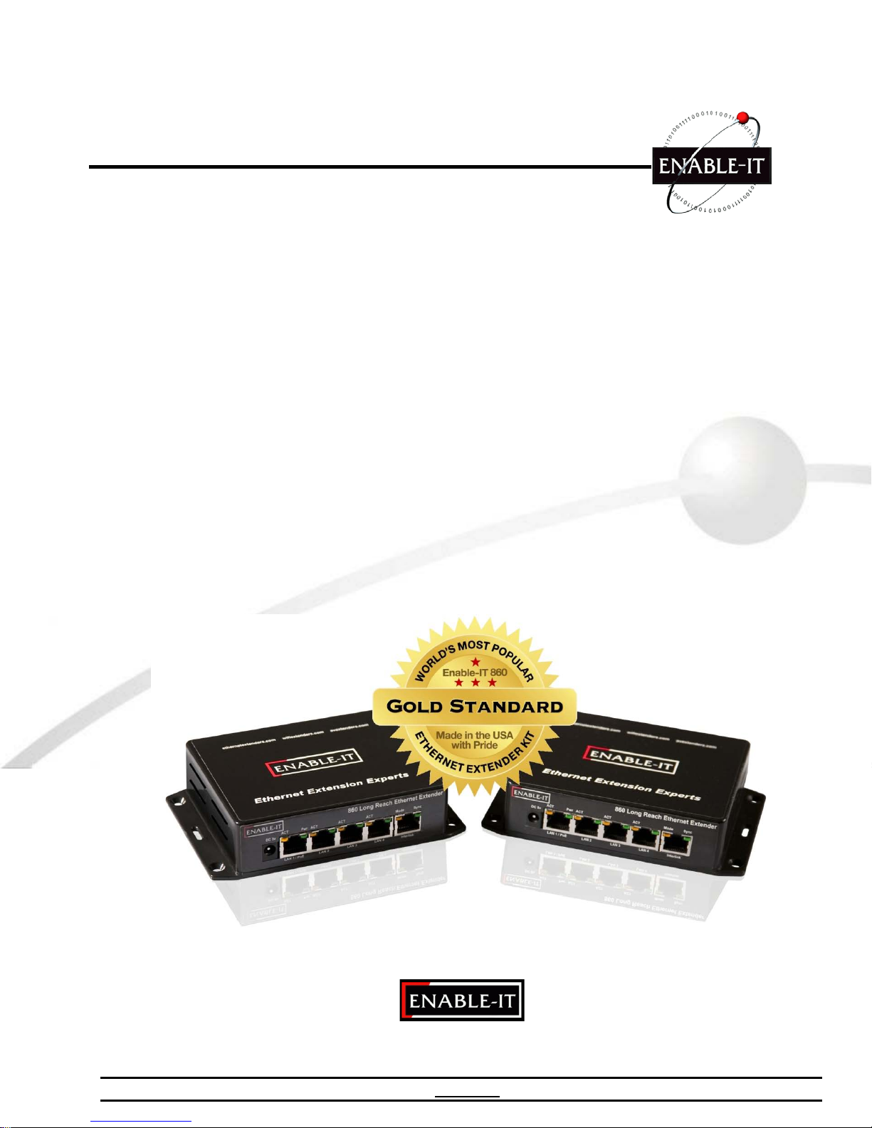
Ethernet Extension Experts
Enable-IT 860 Rev E
Ethernet Extender Kit
User Manual
All Rights Reserved 1997 - 2011 ENABLE-IT - Proprietary and Confidential
Page 2

Copyright © 1997-2011 Enable-IT, Inc. All rights reserved. No part of this documentation
may be reproduced in any form or by any means or use d to make any derivat ive work (such
as translation, transformation, or adaptation) without written perm ission from Enable-IT, Inc.
Enable-IT, Inc reserves the right to revise this documentation and to make changes in
content from time to time without obligation on the part of Enable-IT, Inc to provide
notification of such revision or change.
Enable-IT, Inc provides this documentation without warranty, term, or conditio n of any kind,
either implied or expressed, including, but not limit ed to, the implied warranties, terms or
conditions of merchantability, satisfactory quality, and fitness for a particular purpose.
Enable-IT, Inc may make improvements or changes in the product(s) and/or the
program(s) described in this documentation at any time.
If there is any software on removable media described in this doc umentation, it is furnished
under a license agreement included with the product as a separate document, in the hard
copy documentation. If you are unable to locate a copy, please cont act Enable-IT, Inc and a
copy will be provided to you.
UNITED STATES GOVERNMENT LEGEND
If you are a United States government agency, then this documentation and the software
described herein are provided to you subject to the following:
All technical data and computer software are c ommercial in nature and developed solely at
private expense. Software is delivered as "Commercial Computer Software" as defined in
DFARS 252.227-7014 (June 1995) or as a "commercial item" as def ined in FAR 2.101 (a)
and as such is provided with only such rights as are provided i n Enable-IT, Inc's standard
commercial license for the Software.
Technical data is provided with limited rights only as provided in DFAR 252.227-7015 (Nov
1995) or FAR 52.227-14 (June 1987), whichever is applic able. You agree not to remove or
deface any portion of any legend provided on any licensed program or documentation
contained in, or delivered to you in conjunction with, this User Guide.
Unless otherwise indicated, Enable-IT, Inc registered trademarks are registered in the
United States and may or may not be registered in other countries
Page 2 of 14 Ethernet Extension Experts
Page 3

CONTENTS
ABOUT THIS GUIDE 4
1
INTRODUCING THE ENABLE-IT 860 ETHERNET EXTENDER KIT 5
About the 860 Rev E Ethernet Extender Kit 5
Key Benefits 6
Summary of Features 6
Typical Use Applications 7
2 INSTALLING THE ENABLE-IT 860 ETHERNET EXTENDER UNITS 8
Site Plan – Installation Design Considerations 8
Unpacking the 860 Ethernet Extender Kit 9
Perform an out of the box Test 9
Performing the On-Site Installation 9
Mounting the 860 Ethernet Extender Kit 10
Building the 860 Interlink wiring 10
Attaching cabling and devices 10
Troubleshooting & Performance Settings (DIP switch) 11
3 TECHNICAL SUPPORT
Online Technical Services 11
World Wide Web Site 11
Returning Products for Repair 11
4 ENABLE-IT INC. LIMITED WARRANTY 12
5 CONTACT US 14
Page 3 of 14 Ethernet Extension Experts
Page 4

ABOUT THIS GUIDE
This guide provides all the information needed to install and use the Enable-IT
860 Ethernet Extender Kit. This guide is inte nded for use by technicians who are
responsible for installing and setting up network equipment. Consequently, it is
assumed that the installer has a basic working knowledge of LANs (Local Area
Networks) and voice telecom wiring.
If the information in the release notes that are shipped with your product differs
from the information in this guide, follow the instructions in the release notes.
Most user guides and release notes are available in Adobe Acrobat
Reader Portable Document Format (PDF) or HTML on the Enable-IT World Wide
Web site: http://www.ethernetextender.com/manuals/860 Manual.pdf
Page 4 of 14 Ethernet Extension Experts
Page 5

Unit Model
Wiring
LAN Data Rate
Max. Distance
I
NTRODUCING THE 860 ETHERNET EXTENDER KIT
Congratulations on purchasing the Enable-IT’s 860 Ethernet Extender Kit — the simplest
method to stretch your broadband solutions for in-building deployment in commercial
office buildings, hotels, and multi-tenant residential units.
The 860 Extended Ethernet Unit offers the Lowest Cost Solution in a simple design for
rapid install using existing 1 pair Telco wiring.
This chapter contains introductory information about The 860 Extended Ethernet Unit
and how it can be used in your network. It covers the following topics:
• About the 860 Extended Ethernet Unit
• Key Benefits
• Summary of Features
• Typical Applications
About the 860 Extended Ethernet Kit
The 860 Extended Ethernet Kit solves the problem of high costs associated with
stretching your backbone with traditional fiber or a series of hubs/repeaters.
In many office buildings, preferred network access is a dedicated Ethernet line,
however Ethernet over twisted pair wiring has its distance limitations of just 328 ft. In
order to drive Ethernet signal further, one would have to add repeaters to each
segment of 328ft twisted pair cabling; this is often insuffi cient and to costly in multistory buildings. Fortunately, the Enable-IT 860 Series Extended Ethernet can push
the reach of Ethernet to more than (20) twenty times the typical Ethernet distance
over a 1-pair Telco wiring infrastructure or better.
A simple design methodology would be to think of the 860 extending a standard Ethernet
line up to 6,000 (1,828m) with a (4) Port 10/100 Ethernet switch and can also include
dual voice lines simultaneously.
To increase the durability and extended use of the product providing maximum future
technology protection, 860 Extended Ethernet Unit meets the challenge of modern
switched LANs and allows you to add features and capacity as your network expands.
The Enable-IT 860 Extended Ethernet has been tested to provide full duplex transport
up to 90MB/s over CAT2, and up to 100MB/s over CAT5e cabling.
860 (1) pair CAT 2 up to CAT5e 100Mbps FD 6,000ft / 1, 828m
Up to 700ft (200m) - 100Mbps
700ft (200m) to 1,350ft (400m) - 90Mbps
1,350ft (400m) to 1,970ft (600m) - 70Mbps
1,970ft (600m) to 2,625ft (800m) - 52Mbps
2,625ft (800m) to 3,280ft (1000m) - 42Mbps
3,300ft (1005m) to 6,000(1,828m) - 30Mbps
* Actual data rate will vary on the quality of the copper wire, twisted pair and environmental factors
Page 5 of 14 Ethernet Extension Experts
Page 6

Key Benefits
The following list identifies the 860 Extended Ethernet Unit key benefits.
• Dramatic cost reduction over any competing technology and includes a (4) Port
10/100 LAN switch on each end.
• Broadband technology that delivers in-building Ethernet access over 1 pair of
existing Category 2 up to Category 5e wiring up to 6,000’, whether spare or
actively in use for analog or digital voice. This means no new wiring is required.
• Provides one scalable infrastructure for Internet access, POTS, VoIP, video, and
virtual private networking.
• Rapid installation with small box profile, no programming and no firmware to
upgrade.
• Low profile box with dual POTS line and Ethernet data all in a single RJ-45
Ethernet jack (Interlink port). Optional RJ-11 dongles provided for telephone use
• Quad switched LAN RJ-45 10/100 Ethernet ports for expansion without adding a
hub or switch on each end.
Summary of Features
The Enable-860 Extended Ethernet Kit has the following hardware features:
• Extended Ethernet line over existing CAT 2 up to CAT5e / CAT6 wiring
• Uses RJ-45 Interlink port for transport (Dual voice, 100Mbps data and PoE)
• Rapid Telco style installation – no programming required
• Supports digital VoD channels and Maintains existing telephone (lifeline POTS)
• Drives Ethernet 100 Mbps full-duplex service delivery with quad LAN switch, dual voice
up to 6,000ft or 1,829m - can also transport PoE up to 1,500ft natively.
• Network Equipment independence – Transparent to protocols/applications/MAC
Specifications: Functionality:
Power Indicator Data Rates 100Mbps Full Duplex
100Mbps Link status/Activity Full Duplex/Half Duplex status/Collisions
VDSL2 Link Status/Activity Protocol independent
Dimensions: 860 Interlink port pins:
Height: 1.5" (38mm) Pins 1 & 2 – Voice line 1 and Data
Depth: 3.75" (95mm) Pins 3 & 6 – Voice line 2(optional)
Width: 5.75” (146mm) Pins 4 & 5 – optional support for PoE
Pins 7 & 8 – optional support for PoE
Environment
Operating temp: -49°F to 168°F (-45°to 76°C) Interfaces
Storage temp: -49°F to 168°F (-45°to 76°C) (1) 5v 2A DC Power Adapter 2.1mm
Humidity 5% to 95%, non-condensing (1) Dual head RJ-11 Dongle
(4) RJ-45 100MB LAN Auto negotiate
Dongle pins: DSL center pair (2&3) = Data
Phone –center pair (2&3) = Voice 1 Outside pair (1&4) = Voice 2
Page 6 of 14 Ethernet Extension Experts
Page 7

Typical Use Applications
Enable-IT 860 Extended Ethernet Units are usually installed into telephone wiring
infrastructures where extension of backbone services is required and expensive fiber
options are prohibitive. The 860 Extended Ethernet Units allow a standard Ethernet
segment to be deployed quickly over existing 1 pair Telco Copper Wiring in combination
with existing POTS voice signals. The 860 Interlink port (RJ-45 interface) carries this 1pair signaling over the RJ-45 pins (1 & 2) - used for transport for both voice and data. If
you use more than 1-pair of wiring such as a CAT5 segment, the RJ-45 pins (3 & 4) are
used for Voice line 2 and the remaining pins 4,5,7 & 8 can transport native 802.3af PoE
or are unused. Quad LAN RJ-45 10/100 autosensing ports allow the use of LAN devices
without adding an Ethernet hub or switch to either end. The Option use RJ-11 Dongles
can be used instead of the RJ-45 Interlink port for ease of use or combined RJ-11
Telephone connections.
Installers have the convenience of a 100Mbps LAN Ethernet unit for peace of mind
connectivity and no device maintenance. Rapid installation allows for minimal
interruption and the Broadband technology allows for investment protection up to 10 -15
years with no firmware or replacement issues. Bandwidth can be scaled according to
the Broadband Access Provider needs. The 860 Extended Ethernet Unit is a passive
device so interruption of Internet service does not affect POTS services. Carriers and
Access Providers can came and go, but the 860 Extended Ethernet Unit technologies
continue to provide lasting value such as the other utilities like Water, gas and electricity.
The Enable-860 Extended Ethernet Unit is suited for the following key environments:
• Commercial Buildings (Multi-Tenant Units)
• Business Parks (Multi-Tenant Units)
• Apartments (Multi-Residential Units)
• Hotels (Multi-Hospitality Units)
• Business Suites (Multi-Hospitality Units)
• School Campuses (University, K-12)
• College Housing (Multi-Residential Units)
• Mining Operations – Quarries, Mine shafts
• Nautical Infrastructure – Cruise ships, Marinas, dive operations, subs
• Video Surveillance/Security
• WiFi Deployment – ISP’s, RV Parks, Construction sites
• Manufacturing – Foundries, pharmaceutical, aerospace, automotive,
petroleum, concrete plants, etc.
• Retail POS – Department stores, Bars, restaurants, retail spaces
• Government – Naval ships, FEMA, Housing, USGS, National Parks, Forestry,
Research stations, NASA, utilities, etc.
• Education – outdoor camps, college campuses
• Healthcare – Hospitals, elder care, outpatient facilities
• Entertainment – Movie theaters, home entertainment, fairs, outdoor venues
Page 7 of 14 Ethernet Extension Experts
Page 8
860 CPE
860 CO
I
NSTALLING THE 860 EXTENDED ETHERNET KIT
The Enable-IT 860 Extended Ethernet Units have a distance restriction of 6,000ft or
1,828m over 1-pair of Category 2 up to Category 5e / CAT6 wiring from device extension
to device extension. Therefore quick, simple site surveys and installation planning are
highly recommended.
This chapter describes the recommended installation process for the Enable-IT 860
Extended Ethernet Unit. It covers the following topics:
• Site Plan – Installation Design Considerations
• Unpacking the Enable-IT 860 Extended Ethernet Kits
• Perform an out of the box Test
• Performing the On-Site Installation
Site Plan - Installation Design Considerations
The planning process should involve a site walkthrough and discovery survey. Electrical
Cable measurement tools are the most reliable method to determine the longest run of
hidden wiring. Estimate the best locations to position the Broadband Concentrators to
adequately reach desired connectivity on each floor. Document your findings to use in
designing a network topology to support the Ethernet Switches and backbone
connectivity. Key points to remember in the Site Survey.
• Total distance limitation of 6,000ft or 1,829m from end to end.
• 1 Pair CAT-2 wiring or 4-pair Cat5e .30 Gage or better cabling is required for the
860 Interlink transmission.
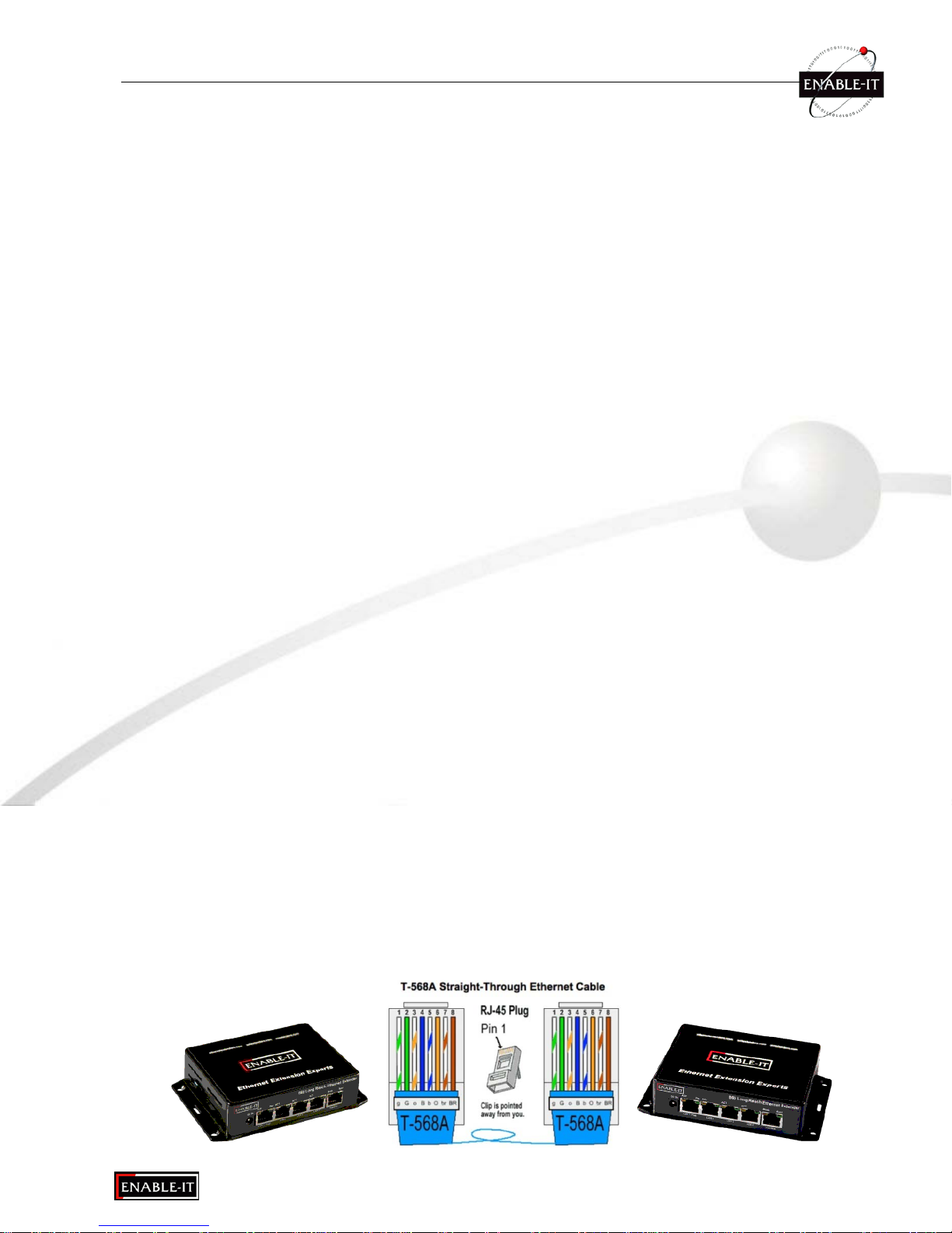
For the Interlink wiring you can use either RJ-45 or RJ-11 connectors. Crimp a RJ45 Male Head to each end of the contiguous wire run and using the following pins (1
& 2) straight through. This will deliver 1 Voice line, Ethernet Data. If you desire to use
the second voice line, you can also use pins (3 & 6) on each end straight through.
The 860 Interlink port (RJ-45 interface) carries this 1-pair signaling over the RJ-45
pins (1 & 2) - used for trans port for both voice and data. If you use more than 1-pair
of wiring such as a CAT5 segment, the RJ-45 pins (3 & 4) are used for Voice line 2
and the remaining pins 4,5,7 & 8 are can transport native PoE or are unused. A s an
option the RJ-11 interface on the side of the 860 for use with existing RJ-11 wiring.
The RJ-11 dongles do not transport PoE currently but can be easily added if needed
on request at time of ordering.
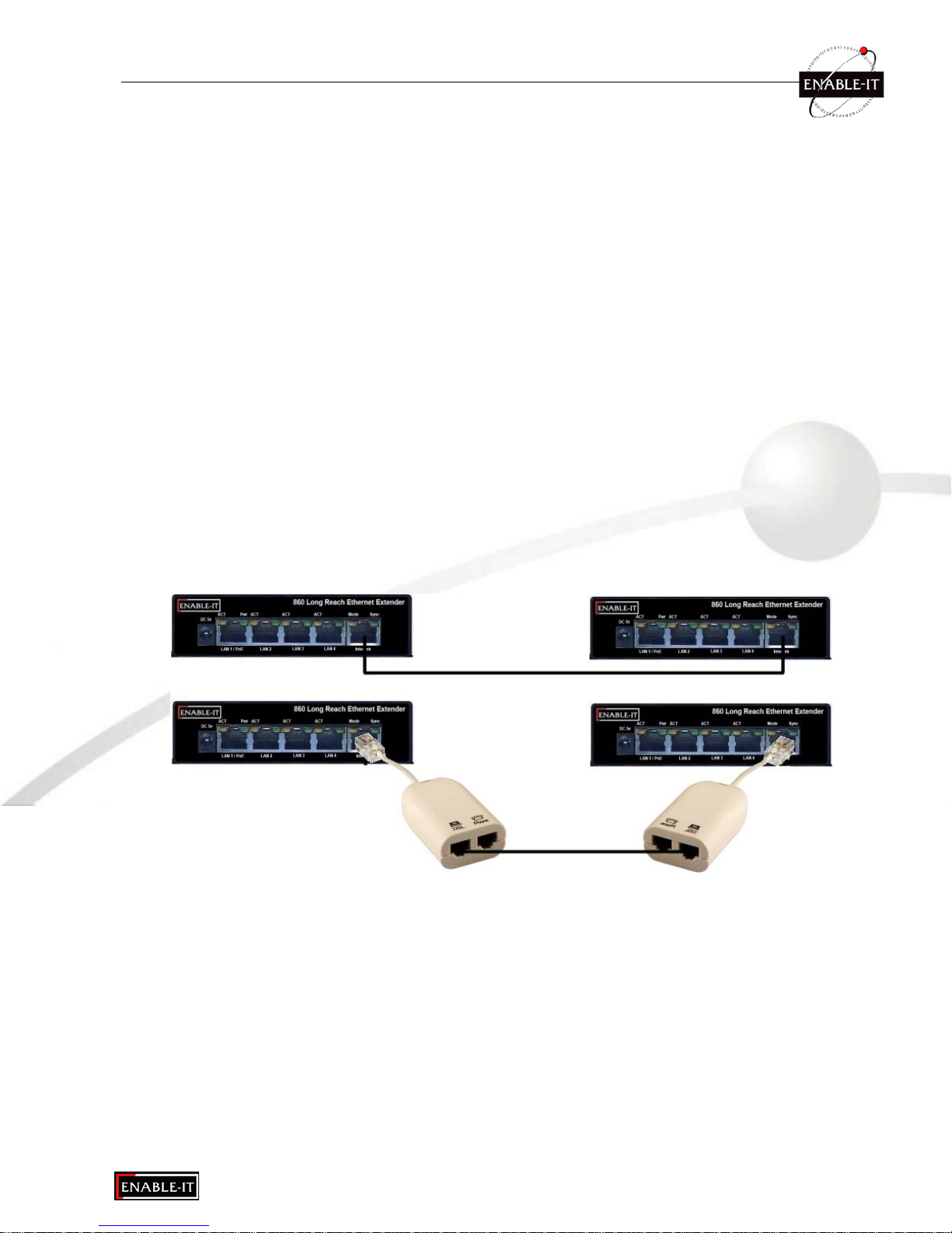
Dongle pins: DSL port center pair (2&3) = Data
Phone port –center pair (2&3) = Voice 1 Outside pair (1&4) = Voice 2
Page 8 of 14 Ethernet Extension Experts
Page 9
860 CO
860 CPE
RJ-45 Interlink
RJ-11 Interlink
DSL port: center pair
Phone port:
Outside pair (1&4) = Voice line 2
Unpacking the Enable-IT 860 Extended Ethernet Kit
Carefully remove the Enable-IT 860 Extended Ethernet Kits all packing materials from
the box. Verify that the items listed below are present. Make sure that the equipment
supplied matches what you ordered. If any items are missing or damaged, please
contact Enable-IT or your distributor for assistance.
• (2) The Enable-IT 860 Extended Ethernet Units (CO & CPE)
o 5v AC/DC Country Specific Power adapter
o 10’ Black Ethernet LAN patch cables
o Dual head RJ-11 DSL Filter/Adapter (for use on active phone system)
• (1) Enable-IT 860 Extended Ethernet Kit User Manual (this manual)
Perform an out of the box Test
We highly recommend a quick test to ensure the working order of you 860 units.
To do this, please use one of the Ethernet patch cords provided and attach to the
860 Interlink port of each 860 unit. Power up both 860 units. The Green Sync
LEDs will start flickering slowly and then fast as the units talk to eachother. After
a few seconds you should see a solid Green Interlink Sync LED on each unit to
confirm a link is established. This confirms basic proper operation of the units.
Next for a more detailed test and to confirm your LAN Equipment works with the
860, connect your Ethernet LAN and remote device to the 860 LAN ports and test
connectivity. The Green Interlink Sync LED will pulse rapidly as it detects traffic.
LED indicators will provide visual operational status of the 860 units.
Sync - Slow to fast flicker on power up – indicates negotiation of a link.
Solid Green LED indicates link established and rapid pulse is traffic.
Pwr - Solid Green LED indicates that both units are receiving 5v power.
Mode - Solid Yellow LED on CPE unit only – No LED lit on CO
ACT - Yellow LEDs – Lit solid indicates the presence of local LAN
– Blinking indicates the presence of local LAN traffic
Performing the On-Site Installation
After removing the Enable-IT 860 Extended Ethernet Kit from the box and performing the
out of the box testing all that remains to install the unit on-site is to mount the unit, build
the interconnect wiring, add voice lines if needed and attach the LAN device cabling with
the provided Ethernet Patch cords.
Page 9 of 14 Ethernet Extension Experts
(2&3) = Interlink Data
Center pair (2&3) = Voice line 1
Page 10
860 CPE
860 CO
Mounting the Enable-IT 860 Extended Ethernet Units
The Enable-IT 860 Extended Ethernet Kits are designed for quick wall mounting.
Choose a location to mount each of the Enable-IT 860’s where the maximum
distance does not exceed 6,000ft or 1,829m total between devices to be connected.
When wall-mounting the Enable-IT 860 Extended Ethernet Kit it is recommended that
you use the appropriate screw anchors for your mounting surface. If mounting on
existing plywood use wood screws; if mounting onto drywall or sheetrock, use plastic
drywall anchors to secure your installation.
Building the 860 Interlink wiring
The most important aspect of the install is the correct wiring of the Interlink cabling.
You have the option of using RJ-45 or RJ-21 blank male heads for this cabling. The
RJ-11 interlink interface and dongle are provided for your convenience in this choice.
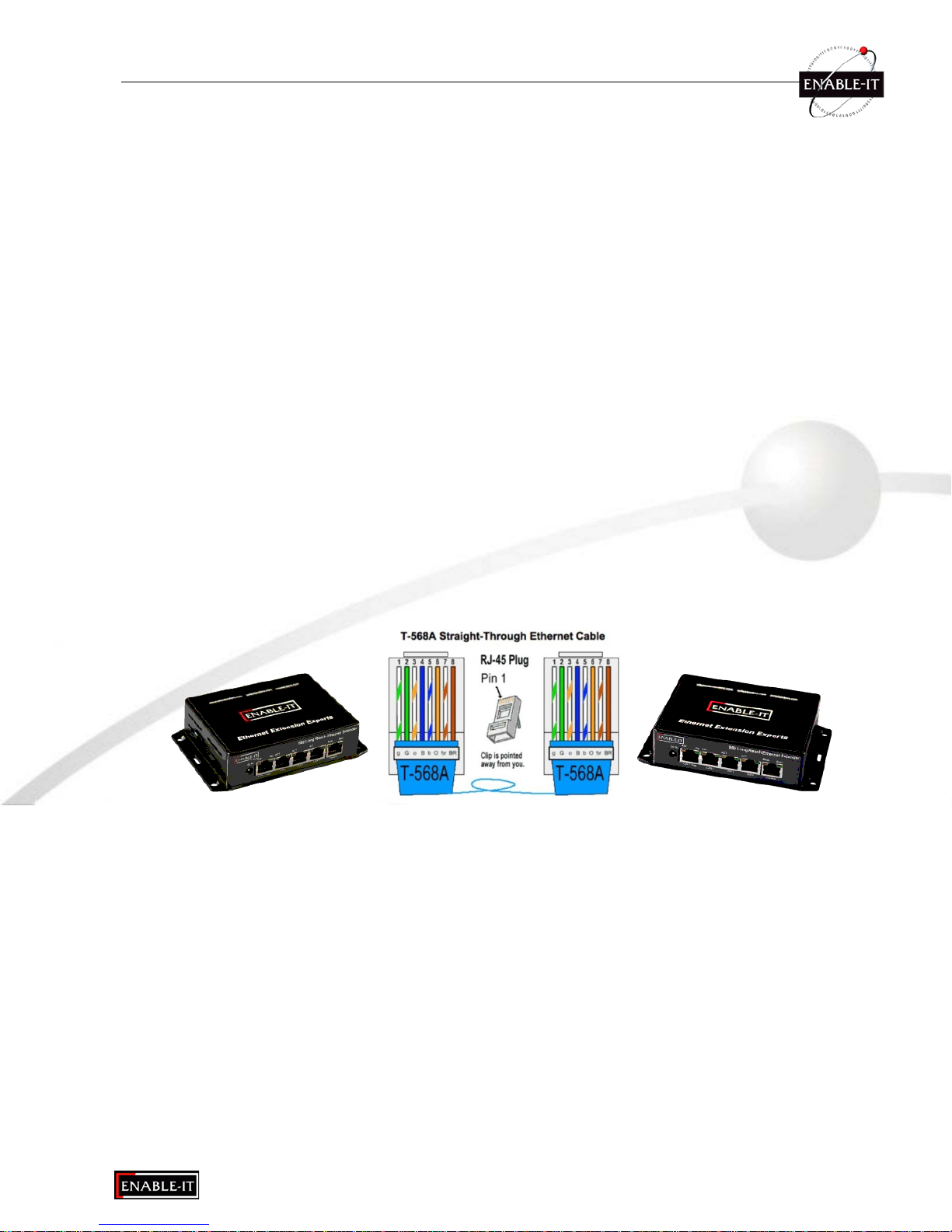
For all wiring you will need to crimp a either a RJ-11 or RJ-45 Male Head to each
end of the contiguous wire run and using the following pins (1 & 2) straight through.
This will deliver 1 Voice line, Ethernet Data. If you desire to use the second voice
line, you can also use pins (3 & 6) on each end straight through. Insert the
completed RJ-45 ends into the 860 Interlink port on each 860 unit or the RJ-11 ends
into the RJ-11 interlink interface and or dongle provided and insert the dongle into
the 860 RJ-11 Interlink port on the right side of each 860 unit.
The 860 Interlink port (RJ-45 interface) carries this 1-pair signaling over the RJ-45
pins (1 & 2) - used for trans port for both voice and data. If you use more than 1-pair
of wiring such as a CAT5 segment, the RJ-45 pins (3 & 4) are used for Voice line 2
and the remaining pins 4,5,7 & 8 are can transport native PoE or are unused.
Attaching cabling and devices to the Enable-IT 860 Extended Ethernet Kit.
Attach your remote LAN device to the 860 CPE unit LAN ports with Ethernet patch
cord provided. Attach your local LAN to the 860 CO LAN ports with Ethernet patch
cord provided. Attach the power adapters to both 860 units.
If you plan on using voice service as well, insert your dial tone voice line/lines into the
RJ-11 dongle and then attach to the 860 CO unit – RJ-11 Interlink port and telephone
handset into the RJ-11 dongle and then attach to the 860 CPE unit RJ-11 Interlink
port. Your equipment should now be powered up and functioning.
LED indicators will provide visual operational status of the 860 units.
Sync - Slow to fast flicker on power up – indicates negotiation of a link.
Solid Green LED indicates link established and rapid pulse is traffic.
Pwr - Solid Green LED indicates that both units are receiving 5v power.
Mode - Solid Yellow LED on CPE unit only – No LED lit on CO
ACT - Yellow LEDs – Lit solid indicates the presence of local LAN
– Blinking indicates the presence of local LAN traffic
Page 10 of 14 Ethernet Extension Experts
Page 11
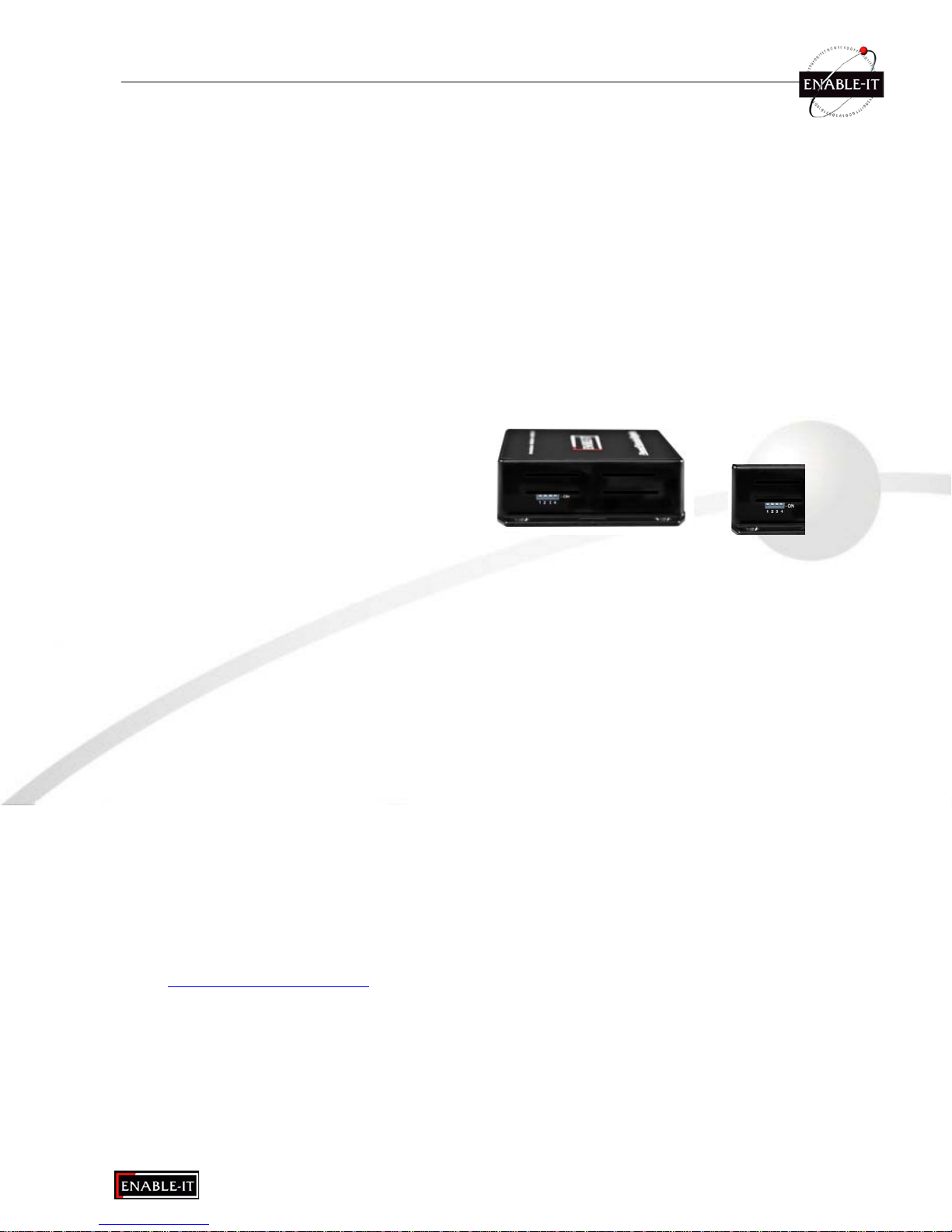
Default DIP settings
For troubleshooting, first examine the backbone wiring pa ir and make sure y ou have solid
connections. The Interlink Sync LED will be lit solid Green with rapid pulsing on each 860
unit to show proper connection and pairing. If the Interli nk Sync LED Link is flashing slow
to fast and never goes solid …. Th en follow the step s below:
1) Make sure your wiring is straight through and not connected to any Telco punch
down block; If so remove from the block and use Telco butt clips to bridge wire.
2) Check for a firm connection of the RJ-45 or RJ-11 connections in eac h 860 unit,
and power is applied to the 860 CO & CPE units.
or your wir ing. It is possi ble an outside interference has been introduced into y our wiring.
Performance Settings
A DIP Switch is provided on the left side of each unit for setting line
performance attributes.
3) You can easily isolate any issue by performing an out of the box test confirm ei ther the 860 Kit
If the Interlink cabling is less than
1,500ft / 457m - Set DIP Switch 3 up
to the OFF position. This optimizes
faster symmetrical throughput.
If the Interlink cabling is over 1,500ft
457m - the DIP switch 3 must be down
(set to ON) position for the unit to work properly.
If you are experiencing performance issues or have interference on your wiring from
the surrounding environment then Set DIP Switch 2 & 4 up (OFF) position to
improve the signal noise ratio. This will clear up any noise that bleeds through over
your wiring and improve the 860 Kit’s performance.
Technical Support
Enable-IT OEM Technical Support is available directly to customers and distributors. All
support requests are processed through the online support portal. This allows us to provide
assigned support ticket numbers in order to bring closure to any technical iss ues.
Online Technical Services
The Enable-IT Support Portal is available 24/7. No password or user account is necessary.
Please use this support website as your first source for help as it contains an on line
knowledge base of articles, documentation, FAQ's and other problem-solving resources. This
web-based support resource provides the quickest solution to the most common technical
support issues.
http://support.enableit.com
Returning Products for Warranty Repair
Enable-IT, Inc. warrants to the original purchaser of the Product ("you" or the "End User")
that, for the four (4) year period commencing on the date the Product was purchased (the
"Warranty Period"), the Product will be substantially free from defects in materials and
workmanship under normal use and conditions. Electrical damage is not an item that is
covered under this warranty or extended warranties.
Page 11 of 14 Ethernet Extension Experts
860 CPE – All down set in the ON position
860 CO – DIP position 1 up (OFF)
DIPs 2-4 down (ON)
Page 12

Returning Products for Refund
Las Vegas
If authorized by Enable-IT to return a Product which does not conform to the warranty set
forth above, the End User must: (1) obtain a return materials authorization (RMA) number
from Enable-IT by contacting the Customer Service Dept. at 888-309-0910 between the
hours of 8:00 a.m. and 5:00 p.m. PST and otherwise fully comply with Enable-IT’s thencurrent RMA policy; (2) return the Product to Enable-IT, Inc. in its original packaging freight
pre-paid; and (3) provide to Enable-IT the original receipt or bill of sale establishing the date
on which the Product was purchased.
Please ship Authorized RMAs to:
Enable-IT Processing Facility
16600 Harbor Blvd, Ste I
Fountain Valley, CA 92708
E
NABLE-IT LIMITED WARRANTY
Enable-IT warrants the Enable-IT 860 Extended Ethernet Kits solely pursuant to the
following terms and conditions.
1. PRODUCT WARRANTY
a. Express Warranty Enable-IT warrants to the original purchaser of the Product ("you" or the
"End User") that, for the four (4) year period commencing on the date the Product was
purchased (the "Warranty Period"), the Product will be substantially free from defects in
materials and workmanship under normal use and conditions. This warranty does not apply
to Products which are resold as used, repaired or reconditioned or consumables (such as
batteries) supplied with the Product. Electrical damage is not an item that is covered
under this warranty or extended warranties. Enable-IT does not make any warranty with
respect to any third party product, software or accessory supplied with or used in connection
with the Product and such third party products, software and a ccessori es, if any, are prov ided
"AS IS." Warranty claims related to such third party products, software and accessories must
be made to the applicable third party m anufacturer.
b. Remedies for Breach of Warranty In the event of a breach of the foregoing warranty,
Enable-IT will, in its sole discretion and at its cost and subject to the terms of the following
paragraph, repair the non-conforming Product, replace the non-conforming Product with a
new or reconditioned Product or refund of the purchase price for the Product. Any new or
reconditioned Product provided pursuant to this paragraph is warranted as provided herein
for the remainder of the original Warranty Period. THE REMEDY SET FORTH IN THIS
PARAGRAPH SHALL BE THE END USER’S SOLE AND EXCLUSIVE REMEDY FOR
BREACH OF THE FOREGOING WARRANTY.
c. Conditions for Warranty Qualification If authorized by Enable-IT to return a Product which
does not conform to the warranty set forth above, the End User must: (1) obtain a return
materials authorization (RMA) number from Enable-IT by contacting the Customer Service
Dept. at 888-309-0910 between the hours of 8:00 a.m. and 5:00 p.m. PST and otherwise fully
comply with Enable-IT’ then-current RMA policy; (2) return the Product to Enable-IT in its
original packaging freight pre-paid; and (3) provide to Enable-IT the original receipt or bill of
sale establishing the date on which the Product was purchased.
Products returned to Enable-IT without an RMA number will be returned to the End User.
Enable-IT shall not be responsible for damage or loss during shipment of the returned
Product to Enable-IT.
45-Day refund applies to single kit Ethernet
Extenders only and is subject to a 15% Restocking
Fee. Shipments without valid / authorized RMA
number or sent to our corporate
Address can be refused and or billed for additional
shipping.
Page 12 of 14 Ethernet Extension Experts
Page 13

d. Voiding of Warranty. The express warranty set forth above shall not apply to failu re of the
Product if the Product has been subjected to: (i) physical abuse, misuse, improper
installation, abnormal use, power failure or surge, or use not consistent with the operating
instructions provided by Enable-IT; (ii) modification (including but not limited to opening the
Product housing) or repair by any party in any manner other than as approved by Enable-IT
in writing; (iii) fraud, tampering, unusual physical or electrical stress, un suitable operating or
physical conditions, negligence or accidents; (iv) removal or alteration of the Product serial
number tag; (v) improper packaging of Product returns; or (vi) dam age during shipment (ot her
than during the original shipment of the Product to the End User from Enable-IT, if
applicable).
e. Warranty Disclaimers THE EXPRESS WARRANTY SET FORTH ABOVE IS IN LIEU OF
ALL OTHER WARRANTIES, WHETHER WRITTEN, ORAL, EXPRESS OR IMPLIED.
ENABLE-IT DISCLAIMS, TO THE MAXIMUM EXTENT PERMITTED BY LAW, THE
IMPLIED WARRANTIES OF MERCHANTABILITY, FITNESS FOR A PARTICULAR
PURPOSE OR NONINFRINGEMENT OF THIRD PARTY RIGHTS. NO PERSON
(INCLUDING WITHOUT LIMITATION, ENABLE-IT’ EMPLOYEES, AGENTS, RESELLERS,
OEMS OR DISTRIBUTORS) IS AUTHORIZED TO MAKE ANY OTHER WARRANTY OR
REPRESENTATION CONCERNING THE PRODUCT. IF THE DISCLAIMER OF ANY
IMPLIED WARRANTY IS NOT PERMITTED BY LAW, THE DURATION OF ANY SUCH
IMPLIED WARRANTY IS LIMITED TO ONE (1) YEAR FROM THE DATE OF PURCHASE.
SOME JURISDICTIONS DO NOT ALLOW THE EXCLUSION OF IMPLIED WARRANTIES
OR LIMITATIONS ON HOW LONG AN IMPLIED WARRANTY MAY LAST, SO SUCH
LIMITATIONS OR EXCLUSIONS MAY NOT APPLY. THIS WARRANTY GIVES THE END
USER SPECIFIC LEGAL RIGHTS AND THE END USER MAY ALSO HAVE OTHER
RIGHTS WHICH VARY FROM JURISDICTION TO JURISDICTION. ENABLE-IT DOES
NOT WARRANT THAT THE OPERATION OF THE PRODUCT WILL BE
UNINTERRUPTED OR ERROR FREE.
ENABLE-IT IS NOT RESPONSIBLE FOR ANY DAMAGE TO OR LOSS OF ANY
PROGRAMS, DATA, OR OTHER INFORMATION STORED ON OR TRANSMITTED
USING THE PRODUCT.
2. LIMITATION OF LIABILITY IN NO EVENT SHALL ENABLE-IT BE LIABLE TO THE END
USER OR ANY THIRD PARTY FOR ANY INDIRECT, SPECIAL, PUNITIVE, INCIDENTAL
OR CONSEQUENTIAL DAMAGES IN CONNECTION WITH OR ARISING OUT OF THE
SALE OR USE OF THE PRODUCT (INCLUDING BUT NOT LIMITED TO LOSS OF
PROFIT, USE, DATA, OR OTHER ECONOMIC ADVANTAGE), HOWEVER IT ARISES,
INCLUDING WITHOUT LIMITATION BREACH OF WARRANTY, OR IN CONTRACT OR IN
TORT (INCLUDING NEGLIGENCE), OR STRICT LIABILITY, EVEN IF ENABLE-IT HAS
BEEN PREVIOUSLY ADVISED OF THE POSSIBILITY OF SUCH DAMAGE AND EVEN IF
A LIMITED REMEDY SET FORTH IN THIS AGREEMENT FAILS OF ITS ESSENTIAL
PURPOSE. IN NO EVENT SHALL ENABLE-IT’ LIABILITY TO THE END USER OR ANY
THIRD PARTY EXCEED THE PRICE PAID FOR THE PRODUCT. BECAUSE SOME
JURISDICTIONS DO NOT ALLOW THE EXCLUSION OR LIMITATION OF LIABILITY FOR
CONSEQUENTIAL OR INCIDENTAL DAMAGES, THE ABOVE LIMITATIONS MAY
NOT APPLY TO THE END USER.
Page 13 of 14 Ethernet Extension Experts
Page 14

3. LICENSE AND LIMITATIONS. The firmware and software embedded in the Product (the
"Embedded Software") are licensed to you. Your use of t he Product is your acceptance of the
warranty terms above and the terms below. You may use the Em bedded Software sole ly in
conjunction with your use of the Product. All worldwide ri ght, title and interest in and to the
Product, or any portion thereof (including but not li mited to the Embedded Software),
including all copyrights, patent rights, trademarks, trade s ecrets, and other intellectual
property rights therein and thereto, are and shall rem ain the exclusive property of Enable-IT
and/or its licensors. You acknowledge and agree that you may not, and may not allow any
third party to, (i) use the Embedded Software in a manner that is inconsistent with the above
express right granted to you or (ii) modify, distribute, reproduce, decompile, disassemble,
reverse engineer or otherwise attempt to discover the source code for the Embedded
Software.
C
ONTACT US
European Sales: North American Sales: Asia Pacific Sales:
+44 1 908 560200 +1 888 309-0910 +61 02 8898-9622
+44 1 908 565533 fax +1 866 389-8605 fax +61 2 9939-0005 fax
http://www.enable-it.eu http://www.enableit.com http://www.enable-it.com.au
[email protected] [email protected] [email protected]
Middle East Sales: Other International:
+971-50-435-8310 +1 702-924-0402
Page 14 of 14 Ethernet Extension Experts
 Loading...