

Enable-IT 824 Quick Start Manual
!
Enable-IT 824!
Gigabit Ethernet Extender
Quickstart Guide
Professional Grade Networking"
All Rights Reserved © 1997 - 2018 Enable-IT™, Inc.
INSTALLING THE 824 GIGABIT ETHERNET EXTENDER
The Enable-IT 824 Gigabit Ethernet Extenders have a distance reach of up to 2,500ft (762m)
over any 1-pair wiring (Telephone, Coax, or Category rated) between the 824 units. You can add
additional 328ft (100m) onto the end of each 824 LAN output ports for a total distance of 3,156ft
(962m) from device extension to device extension. Therefore a site survey of the wiring and
installation planning are highly recommended. For highest performance use lower gauge wiring
like 14AWG ~ 24AWG for the interlink wiring.
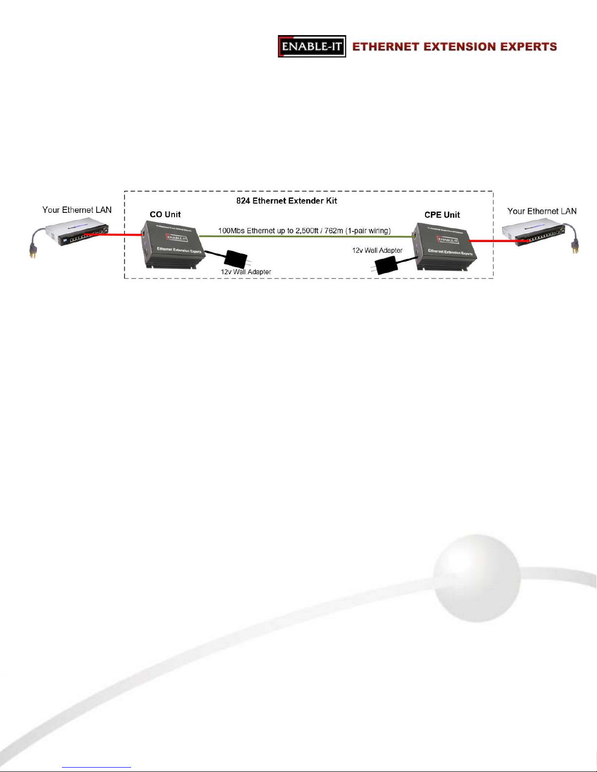
The Overview Diagram: This diagram shows the contents of the product box inside the rectangle. Devices
outside the rectangle above are your equipment that can be attached.
We highly recommend that you perform a quick out of the box test to ensure the working order of your
Enable-IT 824 Gigabit Ethernet Extender units prior to installing. This will also serve to familiarize you
with how easy the process should be. Follow the steps below to perform the Out Of the Box Test.!
!
Step 1 - Attach the 12V DC power adapter to each 824 unit and power up the units. The Power LED !
will indicate the unit is receiving power.!
!
Step 2 - Connect the 824 units together using one of the Ethernet LAN Patch cords provided – attach !
to the RJ-45 Interlink port on each 824 unit as shown by the green line connecting the ports in !
the diagram above. The LED indicators on the 824 LAN ports will provide visual operational !
status of the 824 units.!
!
824 Unit Interlink Side RJ-45 Port LEDs
Mode – Yellow LED OFF = Identified as CO (Master)Unit!
– Yellow LED ON = Identified as CPE (Slave) Unit!
!
Sync – Green LED indicates link established with CPE / Slave unit
Step 3 - Attach and test and to confirm your LAN Equipment works through the 824 extension, connect !
your Ethernet LAN to the 824 CO unit LAN ports and the remote device/s to the 824 CPE !
LAN ports and test connectivity. The Yellow LAN side LEDs will pulse rapidly as it detects traffic.
This confirms basic proper operation of the units.!
Performing the On-Site Installation
After removing the Enable-IT 824 Gigabit Ethernet Extender Kit from the box, and performing
the Out Of The Box Testing (OOTBT), all that remains to install the unit on-site is to mount the
unit, build the interconnect wiring, add voice lines if needed, and attach the LAN device cabling
with the provided Ethernet Patch cords.
All Rights Reserved © 1997 - 2018 Enable-IT™, Inc. Page ! of !2 8
Mounting the Enable-IT 824 Gigabit Ethernet Extender Units!
The Enable-IT 824 extended Ethernet solution is designed for quick wall mounting. Choose a
location to mount each of the Enable-IT 824’s where the maximum distance does not exceed
3,000ft (914m) total between devices to be connected. When wall-mounting the Enable-IT 824
unit it is recommended that you use the appropriate screw anchors for your mounting surface. If
mounting on existing plywood use wood screws; if mounting onto drywall or sheetrock, use
plastic drywall anchors to secure your installation.
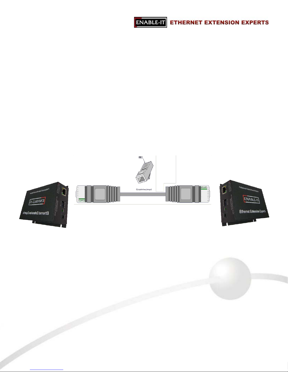
Building the 824 Interlink Wiring!
The most important aspect of the installation is the correct wiring of the Interlink cabling.
The 824 Interlink port (RJ-45 interface) carries this 1-pair signaling over the RJ-45 (pins 1 & 2) used as transport. If you use more than 1-pair of wiring, such as a CAT5 segment, the
remaining RJ-45 pins can transport native 802.3f / 802.3at PoE, or are unused.
For all wiring you will need to crimp a RJ-45 Male head to each end of the contiguous wire run
and using the following (pins 1 & 2) straight through. We recommend using a category rated
twisted pair cable as it is optimized for high throughput frequencies isolated from cross-talk
noise. Insert the completed RJ-45 ends into the 824 Interlink port on each 824 unit.
Cabling Devices to The Enable-IT 824 Extended Ethernet Kit!
Attach your remote LAN device to the 824 CPE unit LAN ports with Ethernet patch cord
provided. Attach your local LAN to the 824 CO LAN ports with Ethernet patch cord provided.
Attach the power adapters to both 824 units.
Attach your local Interlink cabling end to the 824 CO unit Interlink port – Then do the same for
the remote end and plug into the 824 CPE unit Interlink port. The Interlink side Green Sync
LED should be solid, indicating is sees the remote partner. There is no sync delay! Your
equipment should now be powered up and functioning. LED indicators will provide visual
operational status of the 824 units.
All Rights Reserved © 1997 - 2018 Enable-IT™, Inc. Page ! of !3 8
824 CPE Interlink Port
824 CO Interlink Port
RJ-45 Interlink Cabling up to 2,500 feet
Pin 1 & 2
Pin 1 & 2
RJ-45 Head
 Loading...